US5702394A - Assembly piece for an osteosynthesis device - Google Patents
Assembly piece for an osteosynthesis deviceDownload PDFInfo
- Publication number
- US5702394A US5702394AUS08/535,278US53527895AUS5702394AUS 5702394 AUS5702394 AUS 5702394AUS 53527895 AUS53527895 AUS 53527895AUS 5702394 AUS5702394 AUS 5702394A
- Authority
- US
- United States
- Prior art keywords
- portions
- assembly piece
- screw
- slot
- piece according
- Prior art date
- Legal status (The legal status is an assumption and is not a legal conclusion. Google has not performed a legal analysis and makes no representation as to the accuracy of the status listed.)
- Expired - Lifetime
Links
- 239000000463materialSubstances0.000claimsdescription11
- 238000010079rubber tappingMethods0.000claimsdescription4
- 230000001154acute effectEffects0.000claims1
- 229910001069Ti alloyInorganic materials0.000description1
- 230000000295complement effectEffects0.000description1
- 239000007943implantSubstances0.000description1
- 238000009434installationMethods0.000description1
- 230000000284resting effectEffects0.000description1
- 239000007787solidSubstances0.000description1
Images


Classifications
- A—HUMAN NECESSITIES
- A61—MEDICAL OR VETERINARY SCIENCE; HYGIENE
- A61B—DIAGNOSIS; SURGERY; IDENTIFICATION
- A61B17/00—Surgical instruments, devices or methods
- A61B17/56—Surgical instruments or methods for treatment of bones or joints; Devices specially adapted therefor
- A61B17/58—Surgical instruments or methods for treatment of bones or joints; Devices specially adapted therefor for osteosynthesis, e.g. bone plates, screws or setting implements
- A61B17/68—Internal fixation devices, including fasteners and spinal fixators, even if a part thereof projects from the skin
- A61B17/70—Spinal positioners or stabilisers, e.g. stabilisers comprising fluid filler in an implant
- A61B17/7049—Connectors, not bearing on the vertebrae, for linking longitudinal elements together
- A—HUMAN NECESSITIES
- A61—MEDICAL OR VETERINARY SCIENCE; HYGIENE
- A61B—DIAGNOSIS; SURGERY; IDENTIFICATION
- A61B17/00—Surgical instruments, devices or methods
- A61B17/56—Surgical instruments or methods for treatment of bones or joints; Devices specially adapted therefor
- A61B17/58—Surgical instruments or methods for treatment of bones or joints; Devices specially adapted therefor for osteosynthesis, e.g. bone plates, screws or setting implements
- A61B17/60—Surgical instruments or methods for treatment of bones or joints; Devices specially adapted therefor for osteosynthesis, e.g. bone plates, screws or setting implements for external osteosynthesis, e.g. distractors, contractors
- A61B17/64—Devices extending alongside the bones to be positioned
- A61B17/645—Devices extending alongside the bones to be positioned comprising a framework
Definitions
- the present inventionrelates to the field of assembly pieces used in ostheosynthesis, in particular of the spine, and it relates more particularly to a piece for assembling two rods together.
- Publication EP-A-0 383 992discloses an assembly piece used in ostheosynthesis of the spine and serving to interconnect transversely two longitudinal rods that are fixed at several points along their length to the vertebrae. That piece comprises two identical clamp-forming elements for assembling one against the other on a longitudinal rod by means of a threaded rod and two nuts. The assembly pieces are positioned in pairs on the longitudinal rods and the two threaded rods assembling their elements are united by a tapped sleeve for connecting the longitudinal rods together transversely. Installation of the assembly pieces thus makes use of a large number of different elements (nuts, threaded rods, clamp-forming elements, tapped sleeve) which are fiddly to assembly together. In addition, those various elements present projecting angles that run the risk of damaging surrounding tissue.
- the present inventionseeks to remedy those drawbacks and its object is to provide an improved assembly piece which can be installed easily and quickly and which does not risk damaging surrounding tissue.
- this improved assembly piececomprises:
- a body of generally rounded shapehaving a slot separating the body into two portions, and two bores on transverse axes passing obliquely through the slot, each adapted to receive a respective rod to be assembled;
- said bodyis generally spherical in shape, said axes are orthogonal, and said portions are interconnected by a bridge of material defined on the outside by a flat and on the inside by the bottom of the slot, with the slot extending parallel to the flat.
- the screwhas a head for coming axially into abutment against a shoulder formed on one of the portions and the screw has a thread for engaging tapping formed in the other portion.
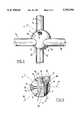
- FIG. 1is a perspective view of an assembly piece of the invention with two rods to be assembled together passing through it;
- FIG. 2is a view from above of the piece shown on its own resting via its flat on a plane surface;
- FIG. 3is a view from beneath of the assembly piece with the two rods passing through it;
- FIG. 4is a view taken in a direction orthogonal to the axes of the rods.
- FIG. 5is a section through the assembly piece on a section plane containing the axis of the screw, and perpendicular to the flat.
- the assembly shown in the figuresis made from a solid body 1 that is preferably constituted by a titanium alloy.
- the outside surface of the body 1is generally in the form of a truncated sphere having a flat 12.
- the body 1is split on an equatorial plane P perpendicular to the flat 12 to form a slot 2 separating two generally hemispherical portions 1a and 1b that are connected together by a bridge of material 1c extending between the flat 12 and the bottom 13 of the slot 2.
- the slot 2is of constant thickness and its bottom 13 is plane and parallel to the flat 12.
- the assembly pieceis bored to receive a first rod T 1 .
- the bore 5 formed in this waypasses through the body 1 along an axis A that intersects both the plane P and the plane tangent to the flat 12 obliquely.
- the bore 5opens out at one end in the outside surface of the portion 1a where it intersects the flat 12 on an elliptical arc 12a, and at its other end it opens out on either side of the plane P in the outside surfaces of the portions 1a and 1b.
- the body 1is also bored to receive a second rod T 2 for assembly with the first T 1 .
- the bore 6 formed in this waypasses through the body 1 on an axis B that is orthogonal to the axis A and that intersects obliquely both the plane P and the plane tangential to the flat 12.
- the bore 6opens out at one end into the outside surface of the portion 1b where it intersects the flat 12 on an elliptical arc 12b, and at its other end it opens out on either side of the plane P in the outside surfaces of the portions 1a and 1b.
- the elliptical arcs 12a and 12bare substantially symmetrical to each other about the plane P and their ends are interconnected by opposite substantially equal circular arcs 12c and 12d.
- the two portions 1a and 1bare connected together by a clamping screw 3 such that tightening the screw locks the two rods T 1 and T 2 in place by clamping them between the portions 1a and 1b.
- the screw 3preferably extends along an axis V perpendicular to the plane P, with the axis V being contained in an equatorial plane of the sphere that is perpendicular to the flat 12.
- the axis Vis situated in that one of the two hemispheres defined by an equatorial plane parallel to the flat 12 which is opposite to the hemisphere carrying the flat 12. More precisely, the axis V passes substantially through the middle of the radius extending between the top of said hemisphere and the above-specified equatorial plane.
- the portion 1ais bored in stepped manner on the axis V to form a shoulder 8, and the screw 3 has a head 14 that comes axially into abutment against the shoulder 8.
- the portion 1bis tapped at 7 along the axis V to receive the thread 4 of the screw 3.
- the thread 4terminates at a non-threaded cylindrical portion 11 connected to that face of the screw head 14 which comes into abutment against the shoulder 8.
- Tightening the screw 3causes the bridge of material 1c to flex about an axis parallel to the axis V and causes the portions 1a and 1b to move towards each other, thereby locking the rods T 1 and T 2 in place by clamping between the portions 1a and 1b.
- the flexibility of the bridge of material 1cdepends, in particular, on its thickness, and by having a flat 12 and a slot 2 with a flat bottom 13 parallel to the flat 12, constant thickness is achieved for the bridge of material without any localized points of weakness.
- the bores 5 and 6open out into the slot 2 at an end that is substantially symmetrical on either side of the plane containing the axis V and perpendicular to the flat 12 so the tubes T 1 and T 2 are clamped with equal force when the screw 3 is tightened, with the screw being tightened by means of a hexagonal key engaged in a socket 10 of complementary shape formed in the end face of the head 14 of the screw.
- the diameter of the sphere defining the body 1is about 15 mm.
- the width of the slot 2is 1 mm and its depth is about 13 mm.
- the thickness of the bridge of material 1c as measured between the bottom 13 of the slot and the flat 12is approximately 1.5 mm.
- the clamping screw 3is 15 mm long, the diameter of the thread 4 is 3 mm and it extends over a length of 8 mm.
- the diameter of the head 14is 6 mm.
- the shoulder 8extends in a plane situated about halfway between the plane P and the plane containing the top of the hemispherical surface defining the portion 1a and parallel to the plane P such that the head 14 of the screw 3 is received for the most part in the circularly cylindrical housing 9 about the axis V and whose bottom constitutes the shoulder 8.
- the thread 4projects little from the tapping 7 and the assembly piece does not present projecting angles that run the risk of damaging surrounding tissue.
- the assembly piece of the inventionis advantageously used for mounting transverse rods between two longitudinal rods that are anchored at several points along their length to the vertebrae by means of implants that are known per se.
- the assembly piecesare threaded by means of one of their respective bores on the longitudinal rods and they are positioned in pairs thereon for receiving transverse rods through their other respective bores.
- both bores in a piecehave the same diameter so a transverse rod can be implemented using a rod of the same kind as the longitudinal rods.
- the present inventionis not limited to the embodiment described above. In particular, it is possible to make the assembly piece out of other biologically compatible materials.
Landscapes
- Health & Medical Sciences (AREA)
- Orthopedic Medicine & Surgery (AREA)
- Surgery (AREA)
- Life Sciences & Earth Sciences (AREA)
- Molecular Biology (AREA)
- Public Health (AREA)
- Engineering & Computer Science (AREA)
- Biomedical Technology (AREA)
- Heart & Thoracic Surgery (AREA)
- Medical Informatics (AREA)
- Neurology (AREA)
- Animal Behavior & Ethology (AREA)
- General Health & Medical Sciences (AREA)
- Nuclear Medicine, Radiotherapy & Molecular Imaging (AREA)
- Veterinary Medicine (AREA)
- Surgical Instruments (AREA)
- Prostheses (AREA)
- Measuring Pulse, Heart Rate, Blood Pressure Or Blood Flow (AREA)
- Spinning Or Twisting Of Yarns (AREA)
- Orthopedics, Nursing, And Contraception (AREA)
- Electrotherapy Devices (AREA)
- Paper (AREA)
Abstract
Description
Claims (12)
Applications Claiming Priority (3)
| Application Number | Priority Date | Filing Date | Title |
|---|---|---|---|
| FR9304625AFR2704134B1 (en) | 1993-04-20 | 1993-04-20 | Assembly piece for osteosynthesis device. |
| FR9304625 | 1993-04-20 | ||
| PCT/FR1994/000437WO1994023661A1 (en) | 1993-04-20 | 1994-04-19 | Mounting member for an osteosynthesis device |
Publications (1)
| Publication Number | Publication Date |
|---|---|
| US5702394Atrue US5702394A (en) | 1997-12-30 |
Family
ID=9446227
Family Applications (1)
| Application Number | Title | Priority Date | Filing Date |
|---|---|---|---|
| US08/535,278Expired - LifetimeUS5702394A (en) | 1993-04-20 | 1994-04-19 | Assembly piece for an osteosynthesis device |
Country Status (15)
| Country | Link |
|---|---|
| US (1) | US5702394A (en) |
| EP (1) | EP0695146B1 (en) |
| JP (1) | JP3533528B2 (en) |
| KR (1) | KR0172152B1 (en) |
| AT (1) | ATE153843T1 (en) |
| AU (1) | AU676312B2 (en) |
| CA (1) | CA2160911C (en) |
| DE (1) | DE69403653T2 (en) |
| DK (1) | DK0695146T3 (en) |
| ES (1) | ES2105697T3 (en) |
| FR (1) | FR2704134B1 (en) |
| GR (1) | GR3024589T3 (en) |
| MX (1) | MXPA94002838A (en) |
| TW (1) | TW242561B (en) |
| WO (1) | WO1994023661A1 (en) |
Cited By (50)
| Publication number | Priority date | Publication date | Assignee | Title |
|---|---|---|---|---|
| US5928243A (en) | 1997-07-16 | 1999-07-27 | Spinal Concepts, Inc. | Pedicle probe and depth gage |
| US5935133A (en) | 1997-08-26 | 1999-08-10 | Spinal Concepts, Inc. | Surgical cable system and method |
| US5989250A (en) | 1996-10-24 | 1999-11-23 | Spinal Concepts, Inc. | Method and apparatus for spinal fixation |
| US6030389A (en) | 1997-08-04 | 2000-02-29 | Spinal Concepts, Inc. | System and method for stabilizing the human spine with a bone plate |
| US6045579A (en) | 1997-05-01 | 2000-04-04 | Spinal Concepts, Inc. | Adjustable height fusion device |
| US6053921A (en) | 1997-08-26 | 2000-04-25 | Spinal Concepts, Inc. | Surgical cable system and method |
| US6132430A (en) | 1996-10-24 | 2000-10-17 | Spinal Concepts, Inc. | Spinal fixation system |
| US6454769B2 (en) | 1997-08-04 | 2002-09-24 | Spinal Concepts, Inc. | System and method for stabilizing the human spine with a bone plate |
| US6610062B2 (en) | 2000-02-16 | 2003-08-26 | Ebi, L.P. | Method and system for spinal fixation |
| US20040138661A1 (en)* | 2003-01-14 | 2004-07-15 | Bailey Kirk J. | Spinal fixation system |
| US20050070901A1 (en)* | 2003-09-26 | 2005-03-31 | Stryker Spine | Bone fixation assembly and method |
| US6964664B2 (en) | 2000-01-06 | 2005-11-15 | Spinal Concepts Inc. | System and method for stabilizing the human spine with a bone plate |
| US20060058787A1 (en)* | 2004-08-24 | 2006-03-16 | Stryker Spine | Spinal implant assembly |
| US20060064088A1 (en)* | 2002-04-04 | 2006-03-23 | Stephane Ramare | Spinal ostesynthesis system |
| US20070288011A1 (en)* | 2006-04-18 | 2007-12-13 | Joseph Nicholas Logan | Spinal Rod System |
| EP1987792A1 (en) | 2007-05-03 | 2008-11-05 | Medartis AG | Fixing device, combination of a fixing device with a long element, assembly with such a combination and osteosynthesis set |
| US7635380B2 (en) | 2007-06-05 | 2009-12-22 | Spartek Medical, Inc. | Bone anchor with a compressor element for receiving a rod for a dynamic stabilization and motion preservation spinal implantation system and method |
| US7637952B2 (en) | 2002-03-11 | 2009-12-29 | Zimmer Spine, Inc. | Instrumentation and procedure for implanting spinal implant devices |
| GB2462424A (en)* | 2008-08-05 | 2010-02-10 | Mark Richard Cunliffe | External fixation clamp |
| US7766947B2 (en) | 2001-10-31 | 2010-08-03 | Ortho Development Corporation | Cervical plate for stabilizing the human spine |
| US7963978B2 (en) | 2007-06-05 | 2011-06-21 | Spartek Medical, Inc. | Method for implanting a deflection rod system and customizing the deflection rod system for a particular patient need for dynamic stabilization and motion preservation spinal implantation system |
| US7993372B2 (en) | 2007-06-05 | 2011-08-09 | Spartek Medical, Inc. | Dynamic stabilization and motion preservation spinal implantation system with a shielded deflection rod system and method |
| US8007518B2 (en) | 2008-02-26 | 2011-08-30 | Spartek Medical, Inc. | Load-sharing component having a deflectable post and method for dynamic stabilization of the spine |
| US8012181B2 (en) | 2008-02-26 | 2011-09-06 | Spartek Medical, Inc. | Modular in-line deflection rod and bone anchor system and method for dynamic stabilization of the spine |
| US8016861B2 (en) | 2008-02-26 | 2011-09-13 | Spartek Medical, Inc. | Versatile polyaxial connector assembly and method for dynamic stabilization of the spine |
| US8021396B2 (en) | 2007-06-05 | 2011-09-20 | Spartek Medical, Inc. | Configurable dynamic spinal rod and method for dynamic stabilization of the spine |
| US8043337B2 (en) | 2006-06-14 | 2011-10-25 | Spartek Medical, Inc. | Implant system and method to treat degenerative disorders of the spine |
| US8048115B2 (en) | 2007-06-05 | 2011-11-01 | Spartek Medical, Inc. | Surgical tool and method for implantation of a dynamic bone anchor |
| US8057515B2 (en) | 2008-02-26 | 2011-11-15 | Spartek Medical, Inc. | Load-sharing anchor having a deflectable post and centering spring and method for dynamic stabilization of the spine |
| US8083775B2 (en) | 2008-02-26 | 2011-12-27 | Spartek Medical, Inc. | Load-sharing bone anchor having a natural center of rotation and method for dynamic stabilization of the spine |
| US8083772B2 (en) | 2007-06-05 | 2011-12-27 | Spartek Medical, Inc. | Dynamic spinal rod assembly and method for dynamic stabilization of the spine |
| US8092501B2 (en) | 2007-06-05 | 2012-01-10 | Spartek Medical, Inc. | Dynamic spinal rod and method for dynamic stabilization of the spine |
| US8097024B2 (en) | 2008-02-26 | 2012-01-17 | Spartek Medical, Inc. | Load-sharing bone anchor having a deflectable post and method for stabilization of the spine |
| US20120016417A1 (en)* | 2010-07-15 | 2012-01-19 | Kyphon Sarl | Flexing links for intervertebral stabilization |
| US8114134B2 (en) | 2007-06-05 | 2012-02-14 | Spartek Medical, Inc. | Spinal prosthesis having a three bar linkage for motion preservation and dynamic stabilization of the spine |
| US8211155B2 (en) | 2008-02-26 | 2012-07-03 | Spartek Medical, Inc. | Load-sharing bone anchor having a durable compliant member and method for dynamic stabilization of the spine |
| US8257397B2 (en) | 2009-12-02 | 2012-09-04 | Spartek Medical, Inc. | Low profile spinal prosthesis incorporating a bone anchor having a deflectable post and a compound spinal rod |
| US8267979B2 (en) | 2008-02-26 | 2012-09-18 | Spartek Medical, Inc. | Load-sharing bone anchor having a deflectable post and axial spring and method for dynamic stabilization of the spine |
| US8333792B2 (en) | 2008-02-26 | 2012-12-18 | Spartek Medical, Inc. | Load-sharing bone anchor having a deflectable post and method for dynamic stabilization of the spine |
| US8337536B2 (en) | 2008-02-26 | 2012-12-25 | Spartek Medical, Inc. | Load-sharing bone anchor having a deflectable post with a compliant ring and method for stabilization of the spine |
| US8430916B1 (en) | 2012-02-07 | 2013-04-30 | Spartek Medical, Inc. | Spinal rod connectors, methods of use, and spinal prosthesis incorporating spinal rod connectors |
| US8480715B2 (en) | 2007-05-22 | 2013-07-09 | Zimmer Spine, Inc. | Spinal implant system and method |
| US8518085B2 (en) | 2010-06-10 | 2013-08-27 | Spartek Medical, Inc. | Adaptive spinal rod and methods for stabilization of the spine |
| US8758343B2 (en) | 2005-04-27 | 2014-06-24 | DePuy Synthes Products, LLC | Bone fixation apparatus |
| US20150133933A1 (en)* | 2011-09-15 | 2015-05-14 | Stryker Trauma Sa | Rod coupler with variable ankle position |
| US9155577B2 (en) | 2003-04-03 | 2015-10-13 | Medartis Ag | Housing for a locking element and locking element |
| US20170100167A1 (en)* | 2012-05-09 | 2017-04-13 | Coligne Ag | Iliac connector, connector head, spinal fixation system and method of stabilizing a spine |
| WO2017055929A3 (en)* | 2015-10-01 | 2017-06-29 | Orion Spine, Inc. | Spine protection device |
| US9907578B2 (en)* | 2008-09-05 | 2018-03-06 | Biedermann Technologies Gmbh & Co. Kg | Bone anchoring element and stabilization device for bones, in particular for the spinal column |
| US20240299065A1 (en)* | 2023-03-08 | 2024-09-12 | Nuvasive, Inc. | Percutaneous posterior fixation |
Families Citing this family (1)
| Publication number | Priority date | Publication date | Assignee | Title |
|---|---|---|---|---|
| US5474551A (en)* | 1994-11-18 | 1995-12-12 | Smith & Nephew Richards, Inc. | Universal coupler for spinal fixation |
Citations (4)
| Publication number | Priority date | Publication date | Assignee | Title |
|---|---|---|---|---|
| GB2033758A (en)* | 1978-10-28 | 1980-05-29 | Aesculap Werke Ag | Fracture fixing appliance |
| EP0509322A1 (en)* | 1991-04-16 | 1992-10-21 | Synthes AG, Chur | Connecting device for the adjustable joint of a first construction element with a second, in particular for tubes or bars for a fixing device |
| EP0517059A1 (en)* | 1991-06-05 | 1992-12-09 | Synthes AG, Chur | Pedicle hook |
| FR2677874A1 (en)* | 1991-06-24 | 1992-12-24 | Sport | Pin for surgery of the hand using the Kapandji method |
Family Cites Families (5)
| Publication number | Priority date | Publication date | Assignee | Title |
|---|---|---|---|---|
| CH408387A (en)* | 1961-01-17 | 1966-02-28 | Bauunternehmung Lorenz Kesting | Box-shaped reinforced concrete structure |
| BE629269A (en)* | 1962-03-06 | |||
| CH633174A5 (en)* | 1978-06-28 | 1982-11-30 | Synthes Ag | Fixator for fixing bone or bone fragments, especially vertebrae |
| US5084049A (en)* | 1989-02-08 | 1992-01-28 | Acromed Corporation | Transverse connector for spinal column corrective devices |
| FR2656214B1 (en)* | 1989-12-26 | 1994-07-22 | Baulny Dominique | DYNAMIC FRAMEWORK OF RACHIS OSTEOSYNTHESIS. |
- 1993
- 1993-04-20FRFR9304625Apatent/FR2704134B1/ennot_activeExpired - Fee Related
- 1994
- 1994-04-19USUS08/535,278patent/US5702394A/ennot_activeExpired - Lifetime
- 1994-04-19MXMXPA94002838Apatent/MXPA94002838A/enactiveIP Right Grant
- 1994-04-19EPEP94913664Apatent/EP0695146B1/ennot_activeExpired - Lifetime
- 1994-04-19AUAU65725/94Apatent/AU676312B2/ennot_activeExpired
- 1994-04-19DEDE69403653Tpatent/DE69403653T2/ennot_activeExpired - Lifetime
- 1994-04-19DKDK94913664.2Tpatent/DK0695146T3/enactive
- 1994-04-19ESES94913664Tpatent/ES2105697T3/ennot_activeExpired - Lifetime
- 1994-04-19ATAT94913664Tpatent/ATE153843T1/enactive
- 1994-04-19KRKR1019950704534Apatent/KR0172152B1/ennot_activeExpired - Lifetime
- 1994-04-19JPJP52284794Apatent/JP3533528B2/ennot_activeExpired - Lifetime
- 1994-04-19WOPCT/FR1994/000437patent/WO1994023661A1/enactiveIP Right Grant
- 1994-04-19CACA002160911Apatent/CA2160911C/ennot_activeExpired - Lifetime
- 1994-06-28TWTW083105836Apatent/TW242561B/zhnot_activeIP Right Cessation
- 1997
- 1997-09-02GRGR970402233Tpatent/GR3024589T3/enunknown
Patent Citations (4)
| Publication number | Priority date | Publication date | Assignee | Title |
|---|---|---|---|---|
| GB2033758A (en)* | 1978-10-28 | 1980-05-29 | Aesculap Werke Ag | Fracture fixing appliance |
| EP0509322A1 (en)* | 1991-04-16 | 1992-10-21 | Synthes AG, Chur | Connecting device for the adjustable joint of a first construction element with a second, in particular for tubes or bars for a fixing device |
| EP0517059A1 (en)* | 1991-06-05 | 1992-12-09 | Synthes AG, Chur | Pedicle hook |
| FR2677874A1 (en)* | 1991-06-24 | 1992-12-24 | Sport | Pin for surgery of the hand using the Kapandji method |
Cited By (114)
| Publication number | Priority date | Publication date | Assignee | Title |
|---|---|---|---|---|
| US6562040B1 (en) | 1996-10-24 | 2003-05-13 | Spinal Concepts, Inc. | Spinal fixation system |
| US6132430A (en) | 1996-10-24 | 2000-10-17 | Spinal Concepts, Inc. | Spinal fixation system |
| US6613050B1 (en) | 1996-10-24 | 2003-09-02 | Spinal Concepts, Inc. | Method and apparatus for spinal fixation |
| US5989250A (en) | 1996-10-24 | 1999-11-23 | Spinal Concepts, Inc. | Method and apparatus for spinal fixation |
| US6595992B1 (en) | 1996-10-24 | 2003-07-22 | Spinal Concepts, Inc. | Method and apparatus for spinal fixation |
| US6416515B1 (en) | 1996-10-24 | 2002-07-09 | Spinal Concepts, Inc. | Spinal fixation system |
| US6576016B1 (en) | 1997-05-01 | 2003-06-10 | Spinal Concepts, Inc. | Adjustable height fusion device |
| US6080193A (en) | 1997-05-01 | 2000-06-27 | Spinal Concepts, Inc. | Adjustable height fusion device |
| US6045579A (en) | 1997-05-01 | 2000-04-04 | Spinal Concepts, Inc. | Adjustable height fusion device |
| US5928243A (en) | 1997-07-16 | 1999-07-27 | Spinal Concepts, Inc. | Pedicle probe and depth gage |
| US6454769B2 (en) | 1997-08-04 | 2002-09-24 | Spinal Concepts, Inc. | System and method for stabilizing the human spine with a bone plate |
| US6030389A (en) | 1997-08-04 | 2000-02-29 | Spinal Concepts, Inc. | System and method for stabilizing the human spine with a bone plate |
| US5935133A (en) | 1997-08-26 | 1999-08-10 | Spinal Concepts, Inc. | Surgical cable system and method |
| US6391030B1 (en) | 1997-08-26 | 2002-05-21 | Spinal Concepts, Inc. | Surgical cable system and method |
| US6053921A (en) | 1997-08-26 | 2000-04-25 | Spinal Concepts, Inc. | Surgical cable system and method |
| US6682533B1 (en) | 1997-08-26 | 2004-01-27 | Spinal Concepts, Inc. | Surgical cable system and method |
| US5964769A (en) | 1997-08-26 | 1999-10-12 | Spinal Concepts, Inc. | Surgical cable system and method |
| US6964664B2 (en) | 2000-01-06 | 2005-11-15 | Spinal Concepts Inc. | System and method for stabilizing the human spine with a bone plate |
| US8025677B2 (en) | 2000-01-06 | 2011-09-27 | Zimmer Spine, Inc. | System and method for stabilizing the human spine with a bone plate |
| US6610062B2 (en) | 2000-02-16 | 2003-08-26 | Ebi, L.P. | Method and system for spinal fixation |
| US7766947B2 (en) | 2001-10-31 | 2010-08-03 | Ortho Development Corporation | Cervical plate for stabilizing the human spine |
| US7637952B2 (en) | 2002-03-11 | 2009-12-29 | Zimmer Spine, Inc. | Instrumentation and procedure for implanting spinal implant devices |
| US7569068B2 (en)* | 2002-04-04 | 2009-08-04 | Kiscomedica | Spinal osteosynthesis system |
| US20060064088A1 (en)* | 2002-04-04 | 2006-03-23 | Stephane Ramare | Spinal ostesynthesis system |
| US20060253118A1 (en)* | 2003-01-14 | 2006-11-09 | Bailey Kirk J | Spinal fixation system |
| US7104992B2 (en) | 2003-01-14 | 2006-09-12 | Ebi, L.P. | Spinal fixation system |
| US20040138661A1 (en)* | 2003-01-14 | 2004-07-15 | Bailey Kirk J. | Spinal fixation system |
| US9155577B2 (en) | 2003-04-03 | 2015-10-13 | Medartis Ag | Housing for a locking element and locking element |
| US20050070901A1 (en)* | 2003-09-26 | 2005-03-31 | Stryker Spine | Bone fixation assembly and method |
| USRE46371E1 (en) | 2003-09-26 | 2017-04-25 | Stryker European Holdings I, Llc | Bone fixation assembly and method |
| US7648522B2 (en) | 2003-09-26 | 2010-01-19 | Stryker Spine | Bone fixation assembly and method |
| US20060058787A1 (en)* | 2004-08-24 | 2006-03-16 | Stryker Spine | Spinal implant assembly |
| US8758343B2 (en) | 2005-04-27 | 2014-06-24 | DePuy Synthes Products, LLC | Bone fixation apparatus |
| US8114133B2 (en) | 2006-04-18 | 2012-02-14 | Joseph Nicholas Logan | Spinal rod system |
| US20070288011A1 (en)* | 2006-04-18 | 2007-12-13 | Joseph Nicholas Logan | Spinal Rod System |
| US8172882B2 (en) | 2006-06-14 | 2012-05-08 | Spartek Medical, Inc. | Implant system and method to treat degenerative disorders of the spine |
| US8043337B2 (en) | 2006-06-14 | 2011-10-25 | Spartek Medical, Inc. | Implant system and method to treat degenerative disorders of the spine |
| US9554837B2 (en) | 2007-05-03 | 2017-01-31 | Medartis Ag | Device for fixing an elongate element in a retaining structure |
| US20080275510A1 (en)* | 2007-05-03 | 2008-11-06 | Medartis Ag | Fixation Device, Combination of a Fixation Device with an Elongate Element, Arrangment with Such a Combination and Osteosynthesis Set |
| EP1987792A1 (en) | 2007-05-03 | 2008-11-05 | Medartis AG | Fixing device, combination of a fixing device with a long element, assembly with such a combination and osteosynthesis set |
| US8480715B2 (en) | 2007-05-22 | 2013-07-09 | Zimmer Spine, Inc. | Spinal implant system and method |
| US8057514B2 (en) | 2007-06-05 | 2011-11-15 | Spartek Medical, Inc. | Deflection rod system dimensioned for deflection to a load characteristic for dynamic stabilization and motion preservation spinal implantation system and method |
| US8147520B2 (en) | 2007-06-05 | 2012-04-03 | Spartek Medical, Inc. | Horizontally loaded dynamic stabilization and motion preservation spinal implantation system and method |
| US7635380B2 (en) | 2007-06-05 | 2009-12-22 | Spartek Medical, Inc. | Bone anchor with a compressor element for receiving a rod for a dynamic stabilization and motion preservation spinal implantation system and method |
| US8021396B2 (en) | 2007-06-05 | 2011-09-20 | Spartek Medical, Inc. | Configurable dynamic spinal rod and method for dynamic stabilization of the spine |
| US8012175B2 (en) | 2007-06-05 | 2011-09-06 | Spartek Medical, Inc. | Multi-directional deflection profile for a dynamic stabilization and motion preservation spinal implantation system and method |
| US7942900B2 (en) | 2007-06-05 | 2011-05-17 | Spartek Medical, Inc. | Shaped horizontal rod for dynamic stabilization and motion preservation spinal implantation system and method |
| US8048115B2 (en) | 2007-06-05 | 2011-11-01 | Spartek Medical, Inc. | Surgical tool and method for implantation of a dynamic bone anchor |
| US8048123B2 (en) | 2007-06-05 | 2011-11-01 | Spartek Medical, Inc. | Spine implant with a deflection rod system and connecting linkages and method |
| US8048122B2 (en) | 2007-06-05 | 2011-11-01 | Spartek Medical, Inc. | Spine implant with a dual deflection rod system including a deflection limiting sheild associated with a bone screw and method |
| US7963978B2 (en) | 2007-06-05 | 2011-06-21 | Spartek Medical, Inc. | Method for implanting a deflection rod system and customizing the deflection rod system for a particular patient need for dynamic stabilization and motion preservation spinal implantation system |
| US8048128B2 (en) | 2007-06-05 | 2011-11-01 | Spartek Medical, Inc. | Revision system and method for a dynamic stabilization and motion preservation spinal implantation system and method |
| US8048121B2 (en) | 2007-06-05 | 2011-11-01 | Spartek Medical, Inc. | Spine implant with a defelction rod system anchored to a bone anchor and method |
| US8048113B2 (en) | 2007-06-05 | 2011-11-01 | Spartek Medical, Inc. | Deflection rod system with a non-linear deflection to load characteristic for a dynamic stabilization and motion preservation spinal implantation system and method |
| US8052722B2 (en) | 2007-06-05 | 2011-11-08 | Spartek Medical, Inc. | Dual deflection rod system for a dynamic stabilization and motion preservation spinal implantation system and method |
| US8052721B2 (en) | 2007-06-05 | 2011-11-08 | Spartek Medical, Inc. | Multi-dimensional horizontal rod for a dynamic stabilization and motion preservation spinal implantation system and method |
| US8568451B2 (en) | 2007-06-05 | 2013-10-29 | Spartek Medical, Inc. | Bone anchor for receiving a rod for stabilization and motion preservation spinal implantation system and method |
| US8002803B2 (en) | 2007-06-05 | 2011-08-23 | Spartek Medical, Inc. | Deflection rod system for a spine implant including an inner rod and an outer shell and method |
| US7985243B2 (en) | 2007-06-05 | 2011-07-26 | Spartek Medical, Inc. | Deflection rod system with mount for a dynamic stabilization and motion preservation spinal implantation system and method |
| US8066747B2 (en) | 2007-06-05 | 2011-11-29 | Spartek Medical, Inc. | Implantation method for a dynamic stabilization and motion preservation spinal implantation system and method |
| US8070780B2 (en) | 2007-06-05 | 2011-12-06 | Spartek Medical, Inc. | Bone anchor with a yoke-shaped anchor head for a dynamic stabilization and motion preservation spinal implantation system and method |
| US8070774B2 (en) | 2007-06-05 | 2011-12-06 | Spartek Medical, Inc. | Reinforced bone anchor for a dynamic stabilization and motion preservation spinal implantation system and method |
| US8070776B2 (en) | 2007-06-05 | 2011-12-06 | Spartek Medical, Inc. | Deflection rod system for use with a vertebral fusion implant for dynamic stabilization and motion preservation spinal implantation system and method |
| US8070775B2 (en) | 2007-06-05 | 2011-12-06 | Spartek Medical, Inc. | Deflection rod system for a dynamic stabilization and motion preservation spinal implantation system and method |
| US8080039B2 (en) | 2007-06-05 | 2011-12-20 | Spartek Medical, Inc. | Anchor system for a spine implantation system that can move about three axes |
| US8317836B2 (en) | 2007-06-05 | 2012-11-27 | Spartek Medical, Inc. | Bone anchor for receiving a rod for stabilization and motion preservation spinal implantation system and method |
| US8083772B2 (en) | 2007-06-05 | 2011-12-27 | Spartek Medical, Inc. | Dynamic spinal rod assembly and method for dynamic stabilization of the spine |
| US8092501B2 (en) | 2007-06-05 | 2012-01-10 | Spartek Medical, Inc. | Dynamic spinal rod and method for dynamic stabilization of the spine |
| US8298267B2 (en) | 2007-06-05 | 2012-10-30 | Spartek Medical, Inc. | Spine implant with a deflection rod system including a deflection limiting shield associated with a bone screw and method |
| US8211150B2 (en) | 2007-06-05 | 2012-07-03 | Spartek Medical, Inc. | Dynamic stabilization and motion preservation spinal implantation system and method |
| US8105356B2 (en) | 2007-06-05 | 2012-01-31 | Spartek Medical, Inc. | Bone anchor with a curved mounting element for a dynamic stabilization and motion preservation spinal implantation system and method |
| US8105359B2 (en) | 2007-06-05 | 2012-01-31 | Spartek Medical, Inc. | Deflection rod system for a dynamic stabilization and motion preservation spinal implantation system and method |
| US8109970B2 (en) | 2007-06-05 | 2012-02-07 | Spartek Medical, Inc. | Deflection rod system with a deflection contouring shield for a spine implant and method |
| US8114130B2 (en) | 2007-06-05 | 2012-02-14 | Spartek Medical, Inc. | Deflection rod system for spine implant with end connectors and method |
| US8114134B2 (en) | 2007-06-05 | 2012-02-14 | Spartek Medical, Inc. | Spinal prosthesis having a three bar linkage for motion preservation and dynamic stabilization of the spine |
| US8002800B2 (en) | 2007-06-05 | 2011-08-23 | Spartek Medical, Inc. | Horizontal rod with a mounting platform for a dynamic stabilization and motion preservation spinal implantation system and method |
| US8118842B2 (en) | 2007-06-05 | 2012-02-21 | Spartek Medical, Inc. | Multi-level dynamic stabilization and motion preservation spinal implantation system and method |
| US8142480B2 (en) | 2007-06-05 | 2012-03-27 | Spartek Medical, Inc. | Dynamic stabilization and motion preservation spinal implantation system with horizontal deflection rod and articulating vertical rods |
| US8192469B2 (en) | 2007-06-05 | 2012-06-05 | Spartek Medical, Inc. | Dynamic stabilization and motion preservation spinal implantation system and method with a deflection rod |
| US8162987B2 (en) | 2007-06-05 | 2012-04-24 | Spartek Medical, Inc. | Modular spine treatment kit for dynamic stabilization and motion preservation of the spine |
| US8172881B2 (en) | 2007-06-05 | 2012-05-08 | Spartek Medical, Inc. | Dynamic stabilization and motion preservation spinal implantation system and method with a deflection rod mounted in close proximity to a mounting rod |
| US7993372B2 (en) | 2007-06-05 | 2011-08-09 | Spartek Medical, Inc. | Dynamic stabilization and motion preservation spinal implantation system with a shielded deflection rod system and method |
| US8177815B2 (en) | 2007-06-05 | 2012-05-15 | Spartek Medical, Inc. | Super-elastic deflection rod for a dynamic stabilization and motion preservation spinal implantation system and method |
| US8182515B2 (en) | 2007-06-05 | 2012-05-22 | Spartek Medical, Inc. | Dynamic stabilization and motion preservation spinal implantation system and method |
| US8182516B2 (en) | 2007-06-05 | 2012-05-22 | Spartek Medical, Inc. | Rod capture mechanism for dynamic stabilization and motion preservation spinal implantation system and method |
| US8057517B2 (en) | 2008-02-26 | 2011-11-15 | Spartek Medical, Inc. | Load-sharing component having a deflectable post and centering spring and method for dynamic stabilization of the spine |
| US8007518B2 (en) | 2008-02-26 | 2011-08-30 | Spartek Medical, Inc. | Load-sharing component having a deflectable post and method for dynamic stabilization of the spine |
| US8211155B2 (en) | 2008-02-26 | 2012-07-03 | Spartek Medical, Inc. | Load-sharing bone anchor having a durable compliant member and method for dynamic stabilization of the spine |
| US8016861B2 (en) | 2008-02-26 | 2011-09-13 | Spartek Medical, Inc. | Versatile polyaxial connector assembly and method for dynamic stabilization of the spine |
| US8048125B2 (en) | 2008-02-26 | 2011-11-01 | Spartek Medical, Inc. | Versatile offset polyaxial connector and method for dynamic stabilization of the spine |
| US8012181B2 (en) | 2008-02-26 | 2011-09-06 | Spartek Medical, Inc. | Modular in-line deflection rod and bone anchor system and method for dynamic stabilization of the spine |
| US8267979B2 (en) | 2008-02-26 | 2012-09-18 | Spartek Medical, Inc. | Load-sharing bone anchor having a deflectable post and axial spring and method for dynamic stabilization of the spine |
| US8097024B2 (en) | 2008-02-26 | 2012-01-17 | Spartek Medical, Inc. | Load-sharing bone anchor having a deflectable post and method for stabilization of the spine |
| US8083775B2 (en) | 2008-02-26 | 2011-12-27 | Spartek Medical, Inc. | Load-sharing bone anchor having a natural center of rotation and method for dynamic stabilization of the spine |
| US8333792B2 (en) | 2008-02-26 | 2012-12-18 | Spartek Medical, Inc. | Load-sharing bone anchor having a deflectable post and method for dynamic stabilization of the spine |
| US8337536B2 (en) | 2008-02-26 | 2012-12-25 | Spartek Medical, Inc. | Load-sharing bone anchor having a deflectable post with a compliant ring and method for stabilization of the spine |
| US8057515B2 (en) | 2008-02-26 | 2011-11-15 | Spartek Medical, Inc. | Load-sharing anchor having a deflectable post and centering spring and method for dynamic stabilization of the spine |
| GB2462424B (en)* | 2008-08-05 | 2012-08-08 | Mark Richard Cunliffe | An external fixation clamp |
| GB2462424A (en)* | 2008-08-05 | 2010-02-10 | Mark Richard Cunliffe | External fixation clamp |
| US9907578B2 (en)* | 2008-09-05 | 2018-03-06 | Biedermann Technologies Gmbh & Co. Kg | Bone anchoring element and stabilization device for bones, in particular for the spinal column |
| US8216281B2 (en) | 2008-12-03 | 2012-07-10 | Spartek Medical, Inc. | Low profile spinal prosthesis incorporating a bone anchor having a deflectable post and a compound spinal rod |
| US8257397B2 (en) | 2009-12-02 | 2012-09-04 | Spartek Medical, Inc. | Low profile spinal prosthesis incorporating a bone anchor having a deflectable post and a compound spinal rod |
| US8394127B2 (en) | 2009-12-02 | 2013-03-12 | Spartek Medical, Inc. | Low profile spinal prosthesis incorporating a bone anchor having a deflectable post and a compound spinal rod |
| US8372122B2 (en) | 2009-12-02 | 2013-02-12 | Spartek Medical, Inc. | Low profile spinal prosthesis incorporating a bone anchor having a deflectable post and a compound spinal rod |
| US8518085B2 (en) | 2010-06-10 | 2013-08-27 | Spartek Medical, Inc. | Adaptive spinal rod and methods for stabilization of the spine |
| US20120016417A1 (en)* | 2010-07-15 | 2012-01-19 | Kyphon Sarl | Flexing links for intervertebral stabilization |
| US20150133933A1 (en)* | 2011-09-15 | 2015-05-14 | Stryker Trauma Sa | Rod coupler with variable ankle position |
| US10194943B2 (en)* | 2011-09-15 | 2019-02-05 | Stryker European Holdings I, Llc | Rod coupler with variable ankle position |
| US8430916B1 (en) | 2012-02-07 | 2013-04-30 | Spartek Medical, Inc. | Spinal rod connectors, methods of use, and spinal prosthesis incorporating spinal rod connectors |
| US20170100167A1 (en)* | 2012-05-09 | 2017-04-13 | Coligne Ag | Iliac connector, connector head, spinal fixation system and method of stabilizing a spine |
| WO2017055929A3 (en)* | 2015-10-01 | 2017-06-29 | Orion Spine, Inc. | Spine protection device |
| CN108601610A (en)* | 2015-10-01 | 2018-09-28 | 钜旺生技股份有限公司 | spinal protector |
| US10792077B2 (en) | 2015-10-01 | 2020-10-06 | Orion Spine Inc. | Spine protection device |
| US20240299065A1 (en)* | 2023-03-08 | 2024-09-12 | Nuvasive, Inc. | Percutaneous posterior fixation |
Also Published As
| Publication number | Publication date |
|---|---|
| CA2160911C (en) | 2003-12-16 |
| ES2105697T3 (en) | 1997-10-16 |
| TW242561B (en) | 1995-03-11 |
| GR3024589T3 (en) | 1997-12-31 |
| DK0695146T3 (en) | 1997-12-22 |
| DE69403653D1 (en) | 1997-07-10 |
| EP0695146A1 (en) | 1996-02-07 |
| FR2704134A1 (en) | 1994-10-28 |
| EP0695146B1 (en) | 1997-06-04 |
| DE69403653T2 (en) | 1998-01-22 |
| FR2704134B1 (en) | 1998-08-28 |
| MXPA94002838A (en) | 2004-06-11 |
| JPH09500035A (en) | 1997-01-07 |
| CA2160911A1 (en) | 1994-10-27 |
| AU676312B2 (en) | 1997-03-06 |
| AU6572594A (en) | 1994-11-08 |
| ATE153843T1 (en) | 1997-06-15 |
| KR0172152B1 (en) | 1999-03-20 |
| JP3533528B2 (en) | 2004-05-31 |
| WO1994023661A1 (en) | 1994-10-27 |
| KR960702281A (en) | 1996-04-27 |
Similar Documents
| Publication | Publication Date | Title |
|---|---|---|
| US5702394A (en) | Assembly piece for an osteosynthesis device | |
| US6248104B1 (en) | Apparatus for osteosynthesis comprising a connector of the spinal pin and the anchoring elements | |
| US5505731A (en) | Screw for lumbar-sacral fixator | |
| KR950006929B1 (en) | Pedicle Screws | |
| KR100329539B1 (en) | Bone plate | |
| US6001098A (en) | Connecting element for spinal stabilizing system | |
| KR0128371B1 (en) | Bone screws | |
| AU754652B2 (en) | Bone alignment system having variable orientation bone anchors | |
| CA2068675C (en) | Locking mechanism for linking anchoring elements in spinal osteosynthesis | |
| US5658284A (en) | Connection member for the connection of a resilient rod with a bone screw which can be anchored in a vertebra | |
| US6660005B2 (en) | Vertebra correcting and fixing device | |
| KR100202329B1 (en) | Spinal structure with band clamp | |
| US6663635B2 (en) | Bone screw with two-part screw head | |
| US6478795B1 (en) | Torque limiting clamping plug for osteosynthesis instrumentation | |
| KR100776776B1 (en) | Bone screw | |
| JP5084195B2 (en) | Bone anchoring device | |
| US5540690A (en) | Spinal fixation system | |
| US6074393A (en) | Bone fixing screws | |
| US6749612B1 (en) | Spinal osteosynthesis system with improved rigidity | |
| US6423064B1 (en) | Orthopaedic screw variable angle connection to a longitudinal support | |
| US20070118124A1 (en) | Bone fixation device and screw therefor | |
| EP0346521A1 (en) | Spinal column fixation device | |
| EP0880942A2 (en) | External minisplint device | |
| EP0879579A2 (en) | Pedicle screw assembly | |
| JPH04506759A (en) | Receiving part for pedicle screw and pedicle screw |
Legal Events
| Date | Code | Title | Description |
|---|---|---|---|
| AS | Assignment | Owner name:STRYKER CORPORATION, MICHIGAN Free format text:ASSIGNMENT OF ASSIGNORS INTEREST;ASSIGNORS:HENRY, PATRICK;LAPRESLE, PHILIPPE;MISSENARD, GILLES;REEL/FRAME:007810/0613 Effective date:19951006 | |
| STCF | Information on status: patent grant | Free format text:PATENTED CASE | |
| AS | Assignment | Owner name:BANK OF AMERICA NATIONAL TRUST AND SAVINGS ASSOCIA Free format text:SECURITY INTEREST;ASSIGNORS:STRYKER CORPORATION;STRYKER FAR EAST, INC.;STRYKER INTERNATIONAL INC.;AND OTHERS;REEL/FRAME:009817/0001 Effective date:19981204 Owner name:BANK OF AMERICA NATIONAL TRUST AND SAVINGS ASSOCIA Free format text:SECURITY AGREEMENT;ASSIGNORS:STRYKER CORPORATION;STRYKER FAR EAST, INC.;REEL/FRAME:014137/0212 Effective date:19981204 | |
| FPAY | Fee payment | Year of fee payment:4 | |
| AS | Assignment | Owner name:STRYKER CORPORATION, MICHIGAN Free format text:RELEASE OF SECURITY INTEREST;ASSIGNOR:BANK OF AMERICA, N.A. (F/K/A BANK OF AMERICA NATIONAL TRUST AND SAVINGS ASSOCIATION);REEL/FRAME:012539/0557 Effective date:20020124 Owner name:STRYKER FAR EAST, INC., MICHIGAN Free format text:RELEASE OF SECURITY INTEREST;ASSIGNOR:BANK OF AMERICA, N.A. (F/K/A BANK OF AMERICA NATIONAL TRUST AND SAVINGS ASSOCIATION);REEL/FRAME:012539/0557 Effective date:20020124 Owner name:STRYKER INTERNATIONAL, INC., MICHIGAN Free format text:RELEASE OF SECURITY INTEREST;ASSIGNOR:BANK OF AMERICA, N.A. (F/K/A BANK OF AMERICA NATIONAL TRUST AND SAVINGS ASSOCIATION);REEL/FRAME:012539/0557 Effective date:20020124 Owner name:HOWMEDICA OSTEONICS CORPORATION, MICHIGAN Free format text:RELEASE OF SECURITY INTEREST;ASSIGNOR:BANK OF AMERICA, N.A. (F/K/A BANK OF AMERICA NATIONAL TRUST AND SAVINGS ASSOCIATION);REEL/FRAME:012539/0557 Effective date:20020124 Owner name:PHYSIOTHERAPY ASSOCIATES, INC., MICHIGAN Free format text:RELEASE OF SECURITY INTEREST;ASSIGNOR:BANK OF AMERICA, N.A. (F/K/A BANK OF AMERICA NATIONAL TRUST AND SAVINGS ASSOCIATION);REEL/FRAME:012539/0557 Effective date:20020124 Owner name:STRYKER PUERTO RICO INC., MICHIGAN Free format text:RELEASE OF SECURITY INTEREST;ASSIGNOR:BANK OF AMERICA, N.A. (F/K/A BANK OF AMERICA NATIONAL TRUST AND SAVINGS ASSOCIATION);REEL/FRAME:012539/0557 Effective date:20020124 Owner name:STRYKER SALES CORPORATION, MICHIGAN Free format text:RELEASE OF SECURITY INTEREST;ASSIGNOR:BANK OF AMERICA, N.A. (F/K/A BANK OF AMERICA NATIONAL TRUST AND SAVINGS ASSOCIATION);REEL/FRAME:012539/0557 Effective date:20020124 Owner name:STRYKER TECHNOLOGIES CORPORATION, MICHIGAN Free format text:RELEASE OF SECURITY INTEREST;ASSIGNOR:BANK OF AMERICA, N.A. (F/K/A BANK OF AMERICA NATIONAL TRUST AND SAVINGS ASSOCIATION);REEL/FRAME:012539/0557 Effective date:20020124 Owner name:STRYKER FOREIGN HOLDCO, INC., MICHIGAN Free format text:RELEASE OF SECURITY INTEREST;ASSIGNOR:BANK OF AMERICA, N.A. (F/K/A BANK OF AMERICA NATIONAL TRUST AND SAVINGS ASSOCIATION);REEL/FRAME:012539/0557 Effective date:20020124 Owner name:SMD CORPORATION, MICHIGAN Free format text:RELEASE OF SECURITY INTEREST;ASSIGNOR:BANK OF AMERICA, N.A. (F/K/A BANK OF AMERICA NATIONAL TRUST AND SAVINGS ASSOCIATION);REEL/FRAME:012539/0557 Effective date:20020124 Owner name:HOWMEDICAL LEIBINGER, INC., MICHIGAN Free format text:RELEASE OF SECURITY INTEREST;ASSIGNOR:BANK OF AMERICA, N.A. (F/K/A BANK OF AMERICA NATIONAL TRUST AND SAVINGS ASSOCIATION);REEL/FRAME:012539/0557 Effective date:20020124 | |
| FPAY | Fee payment | Year of fee payment:8 | |
| FPAY | Fee payment | Year of fee payment:12 |