US5701058A - Method of semiautomatic ambient light sensor calibration in an automatic control system - Google Patents
Method of semiautomatic ambient light sensor calibration in an automatic control systemDownload PDFInfo
- Publication number
- US5701058A US5701058AUS08/582,861US58286196AUS5701058AUS 5701058 AUS5701058 AUS 5701058AUS 58286196 AUS58286196 AUS 58286196AUS 5701058 AUS5701058 AUS 5701058A
- Authority
- US
- United States
- Prior art keywords
- level
- ambient light
- light sensor
- lighting
- illumination level
- Prior art date
- Legal status (The legal status is an assumption and is not a legal conclusion. Google has not performed a legal analysis and makes no representation as to the accuracy of the status listed.)
- Expired - Lifetime
Links
Images


Classifications
- H—ELECTRICITY
- H05—ELECTRIC TECHNIQUES NOT OTHERWISE PROVIDED FOR
- H05B—ELECTRIC HEATING; ELECTRIC LIGHT SOURCES NOT OTHERWISE PROVIDED FOR; CIRCUIT ARRANGEMENTS FOR ELECTRIC LIGHT SOURCES, IN GENERAL
- H05B47/00—Circuit arrangements for operating light sources in general, i.e. where the type of light source is not relevant
- H05B47/10—Controlling the light source
- H05B47/105—Controlling the light source in response to determined parameters
- H05B47/11—Controlling the light source in response to determined parameters by determining the brightness or colour temperature of ambient light
- H—ELECTRICITY
- H05—ELECTRIC TECHNIQUES NOT OTHERWISE PROVIDED FOR
- H05B—ELECTRIC HEATING; ELECTRIC LIGHT SOURCES NOT OTHERWISE PROVIDED FOR; CIRCUIT ARRANGEMENTS FOR ELECTRIC LIGHT SOURCES, IN GENERAL
- H05B47/00—Circuit arrangements for operating light sources in general, i.e. where the type of light source is not relevant
- H05B47/10—Controlling the light source
- H05B47/175—Controlling the light source by remote control
- Y—GENERAL TAGGING OF NEW TECHNOLOGICAL DEVELOPMENTS; GENERAL TAGGING OF CROSS-SECTIONAL TECHNOLOGIES SPANNING OVER SEVERAL SECTIONS OF THE IPC; TECHNICAL SUBJECTS COVERED BY FORMER USPC CROSS-REFERENCE ART COLLECTIONS [XRACs] AND DIGESTS
- Y02—TECHNOLOGIES OR APPLICATIONS FOR MITIGATION OR ADAPTATION AGAINST CLIMATE CHANGE
- Y02B—CLIMATE CHANGE MITIGATION TECHNOLOGIES RELATED TO BUILDINGS, e.g. HOUSING, HOUSE APPLIANCES OR RELATED END-USER APPLICATIONS
- Y02B20/00—Energy efficient lighting technologies, e.g. halogen lamps or gas discharge lamps
- Y02B20/40—Control techniques providing energy savings, e.g. smart controller or presence detection
Definitions
- the present inventionrelates to dimmable lighting systems. More particularly it relates to an improved method of calibrating ambient light levels in lighting systems operated by automatic control systems.
- Such systems for controlling the amount of illumination emitted by a light sourceare typically referred to as dimming control arrangements.
- dimming control arrangementsSuch a system, designed for use with fluorescent lighting, is disclosed in U.S. Pat. No. 4,904,906 assigned to the assignee of the present invention and is hereby incorporated by reference.
- These systemsutilize an ambient light sensor, or photocell, to monitor the ambient light level in a space. The sensor converts the light it receives into an electrical signal. This signal is supplied to an electronic control circuit which adjusts the level or quality of the power supplied to the light source according to a predetermined algorithm.
- This algorithmcan be either proportional, integral, or differential.
- Lighting control system in a typical roomhave a lighting point of interest, typically a work plane and its surroundings, located within an illuminated space, typically a room or other enclosed space within a building.
- Artificial light Ee from an electric light fixture and natural light Eoentering through a window from outside the room illuminate the point of interest.
- Some of the light on the illuminated point of interest and surroundingsis reflected into the ambient light sensor as reflected light Es.
- the light sensoralso referred to as a photocell, is typically mounted in the ceiling above the lighting point of interest, though it may also be mounted anywhere within the illuminated space.
- the sensorconverts the reflected light it receives Es into an electrical signal whose voltage, typically zero to ten volts, is proportional to the light it receives.
- the sensor voltageis supplied to an electronics control circuit which calculates the amount of electrical light that is needed within the illuminated space.
- the control circuitmay be located anywhere, but is typically installed in the sensor, in the light fixture, or in a separate box.
- the algorithm employed by the control circuitmay be either a proportional, integral, and/or differential control system. Lighting control systems typically utilize a proportional control system.
- the parameters of the control algorithmare typically adjustable after installation so that a technician can calibrate the light level at the point of interest to any desired level.
- many systemshave only a setpoint adjustment for the lighting level, ideally both gain and setpoint are adjustable by the technician.
- Other systemshave only one setpoint adjustment, but allow gain adjustment between multiple fixed gains using an automatic switch.
- the Honeywell EL7365 ambient light sensoris an example of such a system.
- the prior artrequires a labor-intensive, trial-and-error calibration process.
- the technicianmanually places a light meter at the point of interest.
- the technicianthen adjusts the lighting parameters, by rotating a potentiometer which changes the resistance in an analog circuit, until the light at the point of interest reaches the desired level.
- the technicianconducts this first reading when there is no outside light Eo at the point of interest, either at night or with the window shades fully closed. Later, with natural sunlight entering the room through the outside window, the parameters are again adjusted until the light at the point of interest reaches the desired level.
- This methodutilizes a light meter and a programmer communicating with the lighting control system.
- the programmersenses the lighting level at the point of interest via the light meter and interactively adjusts the lighting level through the lighting control system, which controls the power controller for the lighting lamps, usually a dimmable ballast.
- the programmercalculates the electronic gain and setpoint required to provide adequate light to the point of interest at any outdoor light level.
- the programmerthen disconnects from the lighting control system and reads the light level at the point of interest at both minimum and maximum outdoor light levels. If these readings do not agree with predicted light levels calculated by the programmer, the programmer makes suggestions to the technician for further adjustments.
- FIG. 1is a diagram illustrating the present invention.
- FIG. 2is a flow diagram of the present invention.
- FIG. 3is a graph of electric light versus control signal for a light adjusted by the present invention.
- FIG. 4is a signal flow diagram of a lighting level control apparatus in accordance with the present invention.
- FIG. 5is a simplified signal flow diagram of a lighting level control apparatus in accordance with the present invention.
- a lighting point of interest 7is located within an illuminated space 8, typically a room or other enclosed space within a building.
- Artificial light Ee from an electric light fixture 9 and natural light Eo, entering through a window 10 from outside the roomilluminate the point of interest 7.
- Some of the light on the illuminated point of interest 7 and its surroundingsis reflected into the ambient light sensor 11 as reflected light Es.
- Light sensor 11also referred to as a photocell, is typically mounted in the ceiling above the lighting point of interest 7, though it may also be mounted anywhere within the illuminated space 8.
- Light sensor 11converts the reflected light Es it receives into an electrical signal whose voltage, typically zero to ten volts, is proportional to the level of the reflected light Es it senses.
- the voltage of light sensoris supplied to dimming electronics 12, which calculate the amount of electrical light Ee that is needed within illuminated space 8.
- Dimming electronics 12may be located anywhere, but are typically installed in the light sensor 11, in or near the light fixture 9, or in a separate box.
- the systemmay be calibrated with the aid of a light meter 13 which can be placed at the illuminated point of interest 7 and measure the illumination level there.
- This light meter 13can be connected to a programmer 15, which in the preferred embodiment is a laptop personal computer but could be any of a number of microprocessor-based devices, whether dedicated or general purpose. This connection may be accomplished by means of an electrically conductive wire 14, radio-frequency, infra-red, or any of a number of well known communications mediums.
- the programmeris in turn connected to the dimming electronics 12, again either by means of an electrically conductive wire 16, radio-frequency, infra-red, or any of a number of well known communications mediums.
- the light meter 13measures the lighting level Ew at the illuminated point of interest 7, and reports the instantaneous lighting level Ew to the programmer.
- the programmer 15calculates the gain and setpoint needed to maintain a constant light level Ew at the illuminated point of interest for variable outside light levels Eo.
- the programmer 15transmits the gain and setpoint to the electronics 12.
- the electronics 12then applies these parameters, e.g. gain and setpoint, to the control algorithm.
- the step-by-step process in FIG. 2illustrates the preferred embodiment, with references to the environment and equipment illustrated in FIG. 1.
- the technicianconducts the installation 18. This involves placing the light meter 13 at the lighting point of interest 7 and connecting the light meter 13 to the programmer 15 if the light meter 13 is not an integral part of the programmer 15. This connection is accomplished by way of physical electrically conductive wires 14 in the preferred embodiment, but may also utilize radio frequency or infrared logical connections.
- the technicianthen "connects" the programmer to the dimming electronics 12.
- This connectioncould be a physical connection, such as electrically conductive wire 16, in a dedicated one-zone system or could include both physical and logical connections if the communications system between the electronics and the programmer is a network.
- One such networkis Echelon's Local Operating Network.
- the desired light level for the illuminated point of interest 8is then entered into programmer 15.
- this stepis accomplished by typing the light level into programmer's 15 keyboard; however, the step could also be accomplished by entering the light level with any other common input device, such as a numeric keypad, or a rotating knob attached to a position sensor, or could be read in from electronic memory or any other data storage medium.
- the programmer 15logically disconnects the ambient light sensor 11 from the dimmer electronics 12, and logically connects the ambient light sensor 11 output to programmer 15 so that it can read the value of Es.
- Programmer 15also connects to dimmer electronics 12 to directly control the electrical light level Ee. This action by the programmer 15 opens the feedback control loop between the ambient light sensor 11 and the dimmer electronics 12.
- programmer 15issues a command to close the shades over the exterior windows 10 to the illuminated space 8.
- this commandis issued to the technician as some sort of visible or audible signal, but the command could also be given audibly or electronically to automated devices which actuate the window blinds.
- the closing of the window blindsblocks the natural light from entering through the exterior windows 10, making Eo approximately zero. Eo does not have to be exactly zero when the blinds are closed but must not contribute significantly to Ew or Es when compared to the light contributed by the electric light fixture 9 when the lights are fully dimmed.
- the technicianhas finished closing the blinds, he indicates the completed action to the programmer 15 by pressing a designated key.
- the techniciancould utilize other known input methods to signal the completion of this step to the programmer 15, or in the case of a fully automated system, the window blind actuators could send a signal back to the programmer 15.
- Measuring subroutine 22then causes the light fixture 9 to go to a minimum level via the connection 16 between the dimmer electronics 12 and the programmer 15.
- the subroutine 22then records the values of Es and Ew as measured by the ambient light sensor 11 and the light meter 13, respectively.
- the subroutine 12then causes the light level Ee to go to a maximum level via the connection 16 between the dimmer electronics 12 and the programmer 15 and records the values of Es and Ew as measured by the ambient light sensor 11 and the light meter 13, respectively.
- programmer 15issues a command to open the shades over the exterior windows 10 to the illuminated space 8.
- this commandis issued to the technician as some sort of visible or audible signal, but the command could also be given audibly or electronically to automated devices which actuate the window blinds.
- the technicianhas finished closing the blinds, he indicates the completed action to the programmer 15 by pressing a designated key.
- the techniciancould utilize other known input methods to signal the completion of this step to the programmer 15, or in the case of a fully automated system, the window blind actuators could send a signal back to the programmer 15.
- Measuring subroutine 24which should optimally be run when the sunlight is approximately perpendicular to the exterior windows 10, then causes the light fixture 9 to go to a minimum level via the connection 16 between the dimmer electronics 12 and programmer 15.
- the optimal time to run the testis any time the sun does not shine directly on the window.
- the subroutine 22then records the values of Es and Ew as measured by the ambient light sensor 11 and the light meter 13, respectively.
- the subroutine 24then causes the light level Ee to go to a maximum level via the connection 16 between the dimmer electronics 12 and the programmer 15 and records the values of Es and Ew as measured by the ambient light sensor 11 and the light meter 13, respectively.
- the two measuring subroutinesobtain four different values for Es and Ew.
- the firstis for the condition of shades closed, minimum electrical light.
- the secondis for the condition of shades closed, maximum electrical light.
- the thirdis for the condition of shades open, minimum electrical light.
- the fourthis for the condition of shades open, maximum electrical light.
- programmer 15After recording each of the lighting levels, Es and Ew, at each of these four conditions, programmer 15 then calculates the values of the electronic gain and setpoint based on the eight measurements made.
- the programmerthen communicates the calculated gain and setpoint values to dimmer electronics 12 where they are stored in non-volatile memory. Sometimes physical arrangements of light sensor 11, exterior window 10, and fixtures within the illuminated space make the calculation of the gain and setpoint impossible or inaccurate. In such a situation, the programmer 15 indicates this condition by displaying an error message.
- programmer 15then logically disconnects itself from the dimming electronics 12 and connects the ambient light sensor 11 to the dimming electronics 12, restoring the lighting feedback loop.
- the electrical light level Eeis now controlled through the dimming electronics 12 by the ambient light sensor 11.
- the programmer 15reads the light meter 13 (with the window shades open) and compares the actual reading of Ew with the desired reading of Ew (as input earlier by the technician or as read from memory or other data storage).
- the programmer 15then issues a command to close the shades over the exterior windows 10 to the illuminated space 8.
- the technician, or an automated systemthen closes the shades and indicates the completion of the action to programmer 15 (typically by pressing a designated key on the programmer).
- Programmer 15reads the light meter 13 (with the window shades closed) and compares the actual reading of Ew with the desired reading of Ew. In block 28, if the readings do not agree within a tolerance for shades open or shades closed, programmer 15 makes suggestions on what adjustments to make to improve the system's performance. In the final step 29, the technician disconnects the programmer 15 and light meter 13. Note that many of the steps above are, or can be, handled automatically by programmer 15, and other steps are routine, for example, connecting light meter 13 or closing and opening the shades. All of the steps are deterministic except block 25, where specific reasons for the failure can be made, and block 28, where the calibration procedure fails completely.
- FIG. 1a typical illuminated space 8 is illustrated with outside light Eo and electric light Ee contributing to the light Ew at an illuminated point of interest 7. It is desired to keep the lighting level at the illuminated point of interest constant, regardless of the level of outside light Eo.
- the signal flow diagram of the systemcan be seen in FIG. 4.
- the light level at the light sensor 11can be stated as:
- Kes, Kos, Kew, and Koware constants calculated by taking the spacial geometry of the illuminated space 8 and the reflectiveness of the materials within the space into account.
- Kow and Kosmay vary with the time of day since the exterior light varies as the sun changes position. It is best to cover the windows with a diffusing material to reduce this time of day variation in exterior light.
- Kew and Kesalso may vary as the furniture, materials, and people within the illuminated space 8 move around.
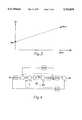
- FIG. 3graphs the electric lighting level Ee produced by the lighting system versus the control signal Ep from the dimming electronics 12 to the electric light ballast, resulting in electric lighting level Ee.
- the transfer function from the control signal to the light outputis Gpe.
- Eeois the minimum light level that the lighting system is capable of producing when Ep is zero.
- the maximum light level that the lighting system is capable of producing from the fixtureis Eem when the control signal Ep is Epm. This relationship can be expressed as:
- the dimming electronics 12multiplies the difference between the light sensor 11 output Es and a preselected setpoint P by a gain constant G, and applies that product to the ballast of the electric light 9.
- FIG. 4illustrates a complete signal flow diagram of electronics 12, lighting fixture 9 and the room's spatial constants. Electronics 12 and lighting fixture 9 are outlined by the dashed lines.
- a new signal flow diagram, illustrated in FIG. 5,can thus be drawn.
- P and Gare variables set by programmer 15 which controls the feedback loop and intensity level Ee of lighting source 9.
- work plane sensor 13measures the ambient light Ew2 with Eo still equal to 0 and Ep equal to Epm.
- Epo in the above two equationsis calculated and the values do not agree within a predetermined tolerance, either the work plane and/or the ambient light sensor is not placed to receive sufficient electric light or the light reaching the sensor is not controlled by the electric light 9.
- Ep and Epois set to 0 by mining the lights off.
- the ambient light at work plane sensor 13is measured as Ew3 and the ambient light sensor 11 measures Es3.
- Pcan be calculated as: ##EQU4## where G is the electronic gain of the feedback loop. P is the setpoint of the feedback loop. Ew0 is the desired work plane light intensity. Epm is a fullscale output value from the lighting controller. Es1 is the ambient light sensor reading with the shades closed and the lights at minimum. Ew1 is the work place sensor reading with the shades closed and the lights at minimum. Es2 is the ambient light sensor reading with the shades closed and the lights at maximum. Ew2 is the work plane sensor reading with the shades closed and the lights at maximum. Es3 is the ambient light sensor reading with the shades open and the lights off and Ew3 is the work plane sensor reading with the shades open and the lights off.
Landscapes
- Circuit Arrangement For Electric Light Sources In General (AREA)
- Photometry And Measurement Of Optical Pulse Characteristics (AREA)
Abstract
Description
The present invention relates to dimmable lighting systems. More particularly it relates to an improved method of calibrating ambient light levels in lighting systems operated by automatic control systems.
With the increased attention on energy-conservation in building design, architects and building owners and operators are utilizing automatically dimming lighting systems to decrease electrical consumption and costs. However, because indoor levels of natural light can vary substantially, based both on predictable variables such as time of day and on unpredictable variables such as weather conditions and shade positions, no predetermined, open-loop dimming schedule can guarantee adequate and even lighting at a given work plane at all times. In an attempt to solve this problem, various parties have developed dimming systems incorporating feedback control of the artificial light output.
Such systems for controlling the amount of illumination emitted by a light source are typically referred to as dimming control arrangements. Such a system, designed for use with fluorescent lighting, is disclosed in U.S. Pat. No. 4,904,906 assigned to the assignee of the present invention and is hereby incorporated by reference. These systems utilize an ambient light sensor, or photocell, to monitor the ambient light level in a space. The sensor converts the light it receives into an electrical signal. This signal is supplied to an electronic control circuit which adjusts the level or quality of the power supplied to the light source according to a predetermined algorithm. This algorithm can be either proportional, integral, or differential.
Lighting control system in a typical room have a lighting point of interest, typically a work plane and its surroundings, located within an illuminated space, typically a room or other enclosed space within a building. Artificial light Ee from an electric light fixture and natural light Eo, entering through a window from outside the room illuminate the point of interest. Some of the light on the illuminated point of interest and surroundings is reflected into the ambient light sensor as reflected light Es. The light sensor, also referred to as a photocell, is typically mounted in the ceiling above the lighting point of interest, though it may also be mounted anywhere within the illuminated space. The sensor converts the reflected light it receives Es into an electrical signal whose voltage, typically zero to ten volts, is proportional to the light it receives. The sensor voltage is supplied to an electronics control circuit which calculates the amount of electrical light that is needed within the illuminated space. The control circuit may be located anywhere, but is typically installed in the sensor, in the light fixture, or in a separate box. The algorithm employed by the control circuit may be either a proportional, integral, and/or differential control system. Lighting control systems typically utilize a proportional control system.
The parameters of the control algorithm are typically adjustable after installation so that a technician can calibrate the light level at the point of interest to any desired level. Although many systems have only a setpoint adjustment for the lighting level, ideally both gain and setpoint are adjustable by the technician. Other systems have only one setpoint adjustment, but allow gain adjustment between multiple fixed gains using an automatic switch. The Honeywell EL7365 ambient light sensor is an example of such a system.
The prior art requires a labor-intensive, trial-and-error calibration process. The technician manually places a light meter at the point of interest. The technician then adjusts the lighting parameters, by rotating a potentiometer which changes the resistance in an analog circuit, until the light at the point of interest reaches the desired level. The technician conducts this first reading when there is no outside light Eo at the point of interest, either at night or with the window shades fully closed. Later, with natural sunlight entering the room through the outside window, the parameters are again adjusted until the light at the point of interest reaches the desired level.
Several factors can complicate this process. First, readjustment is often required so that light at the point of interest remains steady with or without natural daylight Eo. This problem is further complicated because the angle of the daylight entering the room changes with the time of day, since most windows are not equipped with light diffusers. Second, since the adjustment is completely manual, the technician will need to make several time-consuming adjustments to `zero-in` on the desired light settings. Third, if the adjustments are made at the light fixture or the light sensor, the technician must climb a ladder to make a trial adjustment, then climb back down the ladder to avoid blocking the light, and then read the light meter for each adjustment.
It is provided by the present invention, therefore, a method for semi-automatically calibrating an automatic lighting control system which overcomes many of the drawbacks associated with prior art systems. This method utilizes a light meter and a programmer communicating with the lighting control system. The programmer senses the lighting level at the point of interest via the light meter and interactively adjusts the lighting level through the lighting control system, which controls the power controller for the lighting lamps, usually a dimmable ballast. By reading the ambient light levels with the outdoor lighting at both minimum and maximum levels and with the electric lighting at both minimum and maximum levels, the programmer calculates the electronic gain and setpoint required to provide adequate light to the point of interest at any outdoor light level. The programmer then disconnects from the lighting control system and reads the light level at the point of interest at both minimum and maximum outdoor light levels. If these readings do not agree with predicted light levels calculated by the programmer, the programmer makes suggestions to the technician for further adjustments.
Thus it is appreciated that the above described problems are eliminated in a manner as described hereinafter and that further advantages and details of the invention can be had from the following descriptions and claims taken together with the accompanying drawing.
FIG. 1 is a diagram illustrating the present invention.
FIG. 2 is a flow diagram of the present invention.
FIG. 3 is a graph of electric light versus control signal for a light adjusted by the present invention.
FIG. 4 is a signal flow diagram of a lighting level control apparatus in accordance with the present invention.
FIG. 5 is a simplified signal flow diagram of a lighting level control apparatus in accordance with the present invention.
The subject invention and the environment in which it is to be used will initially be described in detail. Following that description, the method of use as well as the mathematical representations will be presented.
Referring to FIG. 1, a lighting point of interest 7, is located within anilluminated space 8, typically a room or other enclosed space within a building. Artificial light Ee from anelectric light fixture 9 and natural light Eo, entering through awindow 10 from outside the room illuminate the point of interest 7. Some of the light on the illuminated point of interest 7 and its surroundings is reflected into theambient light sensor 11 as reflected light Es.Light sensor 11, also referred to as a photocell, is typically mounted in the ceiling above the lighting point of interest 7, though it may also be mounted anywhere within theilluminated space 8.Light sensor 11 converts the reflected light Es it receives into an electrical signal whose voltage, typically zero to ten volts, is proportional to the level of the reflected light Es it senses. The voltage of light sensor is supplied to dimmingelectronics 12, which calculate the amount of electrical light Ee that is needed within illuminatedspace 8.Dimming electronics 12 may be located anywhere, but are typically installed in thelight sensor 11, in or near thelight fixture 9, or in a separate box.
The system may be calibrated with the aid of alight meter 13 which can be placed at the illuminated point of interest 7 and measure the illumination level there. Thislight meter 13 can be connected to aprogrammer 15, which in the preferred embodiment is a laptop personal computer but could be any of a number of microprocessor-based devices, whether dedicated or general purpose. This connection may be accomplished by means of an electricallyconductive wire 14, radio-frequency, infra-red, or any of a number of well known communications mediums. The programmer is in turn connected to thedimming electronics 12, again either by means of an electricallyconductive wire 16, radio-frequency, infra-red, or any of a number of well known communications mediums.
Thelight meter 13 measures the lighting level Ew at the illuminated point of interest 7, and reports the instantaneous lighting level Ew to the programmer. Through a series of measurements initiated by a technician at a programmer's keyboard or keypad or similar data entry device, theprogrammer 15 calculates the gain and setpoint needed to maintain a constant light level Ew at the illuminated point of interest for variable outside light levels Eo. Theprogrammer 15 then transmits the gain and setpoint to theelectronics 12. Theelectronics 12 then applies these parameters, e.g. gain and setpoint, to the control algorithm.
The step-by-step process in FIG. 2 illustrates the preferred embodiment, with references to the environment and equipment illustrated in FIG. 1. Upon entering the illuminatedspace 8, the technician conducts theinstallation 18. This involves placing thelight meter 13 at the lighting point of interest 7 and connecting thelight meter 13 to theprogrammer 15 if thelight meter 13 is not an integral part of theprogrammer 15. This connection is accomplished by way of physical electricallyconductive wires 14 in the preferred embodiment, but may also utilize radio frequency or infrared logical connections. The technician then "connects" the programmer to the dimmingelectronics 12. This connection could be a physical connection, such as electricallyconductive wire 16, in a dedicated one-zone system or could include both physical and logical connections if the communications system between the electronics and the programmer is a network. One such network is Echelon's Local Operating Network.
Inblock 19, the desired light level for the illuminated point ofinterest 8 is then entered intoprogrammer 15. In the preferred embodiment, this step is accomplished by typing the light level into programmer's 15 keyboard; however, the step could also be accomplished by entering the light level with any other common input device, such as a numeric keypad, or a rotating knob attached to a position sensor, or could be read in from electronic memory or any other data storage medium.
Inblock 20, theprogrammer 15 logically disconnects the ambientlight sensor 11 from thedimmer electronics 12, and logically connects the ambientlight sensor 11 output toprogrammer 15 so that it can read the value of Es.Programmer 15 also connects todimmer electronics 12 to directly control the electrical light level Ee. This action by theprogrammer 15 opens the feedback control loop between the ambientlight sensor 11 and thedimmer electronics 12.
Inblock 21,programmer 15 issues a command to close the shades over theexterior windows 10 to the illuminatedspace 8. In the preferred embodiment, this command is issued to the technician as some sort of visible or audible signal, but the command could also be given audibly or electronically to automated devices which actuate the window blinds. The closing of the window blinds blocks the natural light from entering through theexterior windows 10, making Eo approximately zero. Eo does not have to be exactly zero when the blinds are closed but must not contribute significantly to Ew or Es when compared to the light contributed by theelectric light fixture 9 when the lights are fully dimmed. When the technician has finished closing the blinds, he indicates the completed action to theprogrammer 15 by pressing a designated key. In other embodiments, the technician could utilize other known input methods to signal the completion of this step to theprogrammer 15, or in the case of a fully automated system, the window blind actuators could send a signal back to theprogrammer 15.
Measuringsubroutine 22 then causes thelight fixture 9 to go to a minimum level via theconnection 16 between thedimmer electronics 12 and theprogrammer 15. Thesubroutine 22 then records the values of Es and Ew as measured by the ambientlight sensor 11 and thelight meter 13, respectively. Thesubroutine 12 then causes the light level Ee to go to a maximum level via theconnection 16 between thedimmer electronics 12 and theprogrammer 15 and records the values of Es and Ew as measured by the ambientlight sensor 11 and thelight meter 13, respectively.
Inblock 23,programmer 15 issues a command to open the shades over theexterior windows 10 to the illuminatedspace 8. Again, in the preferred embodiment, this command is issued to the technician as some sort of visible or audible signal, but the command could also be given audibly or electronically to automated devices which actuate the window blinds. When the technician has finished closing the blinds, he indicates the completed action to theprogrammer 15 by pressing a designated key. In other embodiments, the technician could utilize other known input methods to signal the completion of this step to theprogrammer 15, or in the case of a fully automated system, the window blind actuators could send a signal back to theprogrammer 15.
Measuringsubroutine 24, which should optimally be run when the sunlight is approximately perpendicular to theexterior windows 10, then causes thelight fixture 9 to go to a minimum level via theconnection 16 between thedimmer electronics 12 andprogrammer 15. When the window faces away from the sun most of the day (Example: North facing window in the northern hemisphere), then the optimal time to run the test is any time the sun does not shine directly on the window. Thesubroutine 22 then records the values of Es and Ew as measured by the ambientlight sensor 11 and thelight meter 13, respectively. Thesubroutine 24 then causes the light level Ee to go to a maximum level via theconnection 16 between thedimmer electronics 12 and theprogrammer 15 and records the values of Es and Ew as measured by the ambientlight sensor 11 and thelight meter 13, respectively.
The two measuring subroutines obtain four different values for Es and Ew. The first is for the condition of shades closed, minimum electrical light. The second is for the condition of shades closed, maximum electrical light. The third is for the condition of shades open, minimum electrical light. The fourth is for the condition of shades open, maximum electrical light.
After recording each of the lighting levels, Es and Ew, at each of these four conditions,programmer 15 then calculates the values of the electronic gain and setpoint based on the eight measurements made.
This process, indicated byblock 25 is described in detail later in this specification in connection with FIGS. 3-5 and the associated equations. The programmer then communicates the calculated gain and setpoint values todimmer electronics 12 where they are stored in non-volatile memory. Sometimes physical arrangements oflight sensor 11,exterior window 10, and fixtures within the illuminated space make the calculation of the gain and setpoint impossible or inaccurate. In such a situation, theprogrammer 15 indicates this condition by displaying an error message.
Inblock 26,programmer 15 then logically disconnects itself from the dimmingelectronics 12 and connects the ambientlight sensor 11 to the dimmingelectronics 12, restoring the lighting feedback loop. The electrical light level Ee is now controlled through the dimmingelectronics 12 by the ambientlight sensor 11. Theprogrammer 15 reads the light meter 13 (with the window shades open) and compares the actual reading of Ew with the desired reading of Ew (as input earlier by the technician or as read from memory or other data storage). Theprogrammer 15 then issues a command to close the shades over theexterior windows 10 to the illuminatedspace 8. The technician, or an automated system, then closes the shades and indicates the completion of the action to programmer 15 (typically by pressing a designated key on the programmer).Programmer 15 reads the light meter 13 (with the window shades closed) and compares the actual reading of Ew with the desired reading of Ew. Inblock 28, if the readings do not agree within a tolerance for shades open or shades closed,programmer 15 makes suggestions on what adjustments to make to improve the system's performance. In thefinal step 29, the technician disconnects theprogrammer 15 andlight meter 13. Note that many of the steps above are, or can be, handled automatically byprogrammer 15, and other steps are routine, for example, connectinglight meter 13 or closing and opening the shades. All of the steps are deterministic exceptblock 25, where specific reasons for the failure can be made, and block 28, where the calibration procedure fails completely.
Referring to FIG. 1, a typicalilluminated space 8 is illustrated with outside light Eo and electric light Ee contributing to the light Ew at an illuminated point of interest 7. It is desired to keep the lighting level at the illuminated point of interest constant, regardless of the level of outside light Eo. The signal flow diagram of the system can be seen in FIG. 4.
As seen in FIG. 4, the light level at thelight sensor 11, can be stated as:
Es=Ee*Kes+Eo*Kos (Equation 1)
and the light level at the illuminated point of interest 7 can be stated as:
Ew=Ee*Kew+Eo*Kow (Equation 2)
where Kes, Kos, Kew, and Kow are constants calculated by taking the spacial geometry of the illuminatedspace 8 and the reflectiveness of the materials within the space into account. Note that Kow and Kos may vary with the time of day since the exterior light varies as the sun changes position. It is best to cover the windows with a diffusing material to reduce this time of day variation in exterior light. Kew and Kes also may vary as the furniture, materials, and people within the illuminatedspace 8 move around.
FIG. 3 graphs the electric lighting level Ee produced by the lighting system versus the control signal Ep from the dimmingelectronics 12 to the electric light ballast, resulting in electric lighting level Ee. In the graph in FIG. 3, the transfer function from the control signal to the light output is Gpe. Where Eeo is the minimum light level that the lighting system is capable of producing when Ep is zero. The maximum light level that the lighting system is capable of producing from the fixture is Eem when the control signal Ep is Epm. This relationship can be expressed as:
Ee=Eeo+Ep*Gpe (Equation 3)
Substituting Epo for Eeo/Gpe results in
Ee=Gpe*(Epo+Ep) (Equation 4)
The dimmingelectronics 12 multiplies the difference between thelight sensor 11 output Es and a preselected setpoint P by a gain constant G, and applies that product to the ballast of theelectric light 9. FIG. 4 illustrates a complete signal flow diagram ofelectronics 12,lighting fixture 9 and the room's spatial constants.Electronics 12 andlighting fixture 9 are outlined by the dashed lines.
Note that Gpe and Kes can be combined into a single gain constant, Kps, where Kps=Kes*Gpe. Gpe and Kew can also be combined into a single gain constant, Kpw, where Kpw=Kew*Gpe. A new signal flow diagram, illustrated in FIG. 5, can thus be drawn.
Referring to the flow diagram of FIG. 5, it can be seen that: ##EQU1## If Ew is independent of Eo, then:
Kow-Kos*Kpw*G=0 (Equation 6)
This yields: ##EQU2## Solving for P: ##EQU3##
By utilizing the method depicted in FIG. 2 it is possible to calculate the values of P and G. P and G are variables set byprogrammer 15 which controls the feedback loop and intensity level Ee oflighting source 9. Measuringsubroutine 22 measures thework plane sensor 13 light intensity (Ew1) when Eo=0 and Ep=0. Measuringsubroutine 22 also measures the ambientlight sensor 11 light intensity (Es1) when Eo=0 and Ep=0. When the intensity oflight fixture 9 is set at max, (Ep is set at Epm)work plane sensor 13 measures the ambient light Ew2 with Eo still equal to 0 and Ep equal to Epm. The ambientlight sensor 13 measures Es2 which is the ambient light when Eo=0 and Ep=Epm. Based on these measured values Epo can be calculated as:
Epo=Ew1*Epm/(Ew2-Ew1) (Equation 9)
Epo=Es1*Epm/(Es2-Es1) (Equation 10)
If Epo in the above two equations is calculated and the values do not agree within a predetermined tolerance, either the work plane and/or the ambient light sensor is not placed to receive sufficient electric light or the light reaching the sensor is not controlled by theelectric light 9.
G= Epm/(Ew2-Ew1)!* Ew3/Es3!; (Equation 11)
P can be calculated as: ##EQU4## where G is the electronic gain of the feedback loop. P is the setpoint of the feedback loop. Ew0 is the desired work plane light intensity. Epm is a fullscale output value from the lighting controller. Es1 is the ambient light sensor reading with the shades closed and the lights at minimum. Ew1 is the work place sensor reading with the shades closed and the lights at minimum. Es2 is the ambient light sensor reading with the shades closed and the lights at maximum. Ew2 is the work plane sensor reading with the shades closed and the lights at maximum. Es3 is the ambient light sensor reading with the shades open and the lights off and Ew3 is the work plane sensor reading with the shades open and the lights off.
By following the method described herein, one is able to calculate G and P and set thedimmer electronics 12 in order to maintain a constant light intensity at work surface 7.
Claims (9)
1. A method of calibrating a dimmable lighting system, having an electric lighting fixture, or ambient light sensor, an electronic controller and a programmer for controlling a feedback loop between said ambient light sensor and said electronic controller, comprising the steps of:
adjusting an output level of an electric lighting fixture in a workspace to a minimum and adjusting an outdoor light level in the workspace to a minimum;
sensing and recording a first illumination level at an ambient light sensor and a first illumination level at a lighting point of interest;
adjusting the output level of the electric lighting fixture to a maximum;
sensing and recording a second illumination level at said ambient light sensor and a second illumination level at said lighting point of interest;
adjusting said outdoor light level to a maximum and adjusting said electric lighting fixture output level to a minimum;
sensing and recording a third illumination level at the ambient light sensor and a third illumination level at the lighting point of interest;
adjusting said output level of said electric lighting fixture to a maximum while holding said outdoor light level at a maximum;
sensing and recording a fourth illumination level at the ambient light sensor and a fourth illumination level at the lighting point of interest;
calculating a gain value and a setpoint value for said dimmable lighting system from the eight sensed illumination levels and a predetermined illumination level at the lighting point of interest;
communicating the gain value and the setpoint value to the electronic controller of the dimmable lighting system, said electronic controller utilized to control an electrical input to the electric lighting fixture.
2. A method in accordance with claim 1 wherein at least one of the steps is performed by an electronic programmer connected to a light meter and the electronic controller, said light meter located at the lighting point of interest to sense the illumination level.
3. A method in accordance with claim 2 including the additional steps of:
connecting the electronic programmer to the electronic controller;
electrically disconnecting the ambient light sensor from the electronic controller;
electrically connecting the ambient light sensor to the electronic programmer;
electrically disconnecting the ambient light sensor from the electronic programmer;
electrically reconnecting the ambient light sensor to the electronic controller; and
disconnecting the electronic programmer from the electronic controller.
4. A method in accordance with claim 1, further comprising the steps of:
connecting the electronic controller to the ambient light sensor;
controlling the light output of the electric light fixture with the electronic controller;
adjusting the outdoor lighting level to a maximum;
sensing and recording a first illumination level at the lighting point of interest;
comparing the first illumination level to the predetermined illumination level for the lighting point of interest;
adjusting the outdoor lighting level to a minimum;
sensing and recording a second illumination level at the lighting point of interest;
comparing the second illumination level to the predetermined illumination level for the lighting point of interest;
determining an appropriate adjustment based on a difference between the first illumination level and the predetermined illumination level and between the second illumination level and the predetermined illumination level.
5. A method in accordance with claim 4 wherein at least one of the steps is performed by an electronic programmer connected to a light meter and the electronic controller, said light meter located at the lighting point of interest to sense the illumination level.
6. A method in accordance with claim 5 including the additional steps of:
connecting the electronic programmer to the electronic controller;
electrically disconnecting the ambient light sensor from the electronic controller;
electrically connecting the ambient light sensor to the electronic programmer;
electrically disconnecting the ambient light sensor from the electronic programmer;
electrically reconnecting the ambient light sensor to the electronic controller; and
disconnecting the electronic programmer from the electronic controller.
7. A method of calibrating a dimmable lighting system wherein said lighting system comprises a programmer for controlling a feedback loop between an ambient light sensor and an electronic controller, comprising the steps of:
adjusting an output level of an electric lighting fixture in a workspace to a minimum and adjusting an outdoor light level in the workspace to a minimum;
sensing and recording a first illumination level ES1 at an ambient light sensor and a first illumination level EW1 at a lighting point of interest;
adjusting the output level of the electric lighting fixture to a maximum EPM ;
sensing and recording a second illumination level ES2 at the ambient light sensor and a second illumination level EW2 at the lighting point of interest;
adjusting the outdoor light level to a maximum and adjusting the electric lighting fixture output level to a minimum;
sensing and recording a third illumination level ES3 at the ambient light sensor and a third illumination level EW3 at the lighting point of interest;
adjusting the output level of the electric lighting fixture to a maximum while holding the outdoor light level at a maximum;
sensing and recording a fourth illumination level ES4 at the ambient light sensor and a fourth illumination level EW4 at the lighting point of interest;
calculating a gain value and a setpoint value for the dimmable lighting system from the eight sensed illumination levels and a predetermined illumination level EW0 at the lighting point of interest;
whereby the gain value is determined from the equation:
G= E.sub.PM /(E.sub.W2 -E.sub.W1)!* E.sub.W3 /E.sub.S3 !;
and the setpoint value is determined from the equation:
P={E.sub.W0 * 1+(E.sub.S1 /E.sub.W1 * (E.sub.W3 /E.sub.S3)!-E.sub.W1 }/(E.sub.W3 /E.sub.S3);communicating the gain value and the setpoint value to the electronic controller of the dimmable lighting system, said electronic controller utilized to control an electrical input to the electric lighting fixture.
8. A method in accordance with claim 7 wherein at least one of the steps is performed by an electronic programmer connected to a light meter and the electronic controller, said light meter located at the lighting point of interest to sense the illumination level.
9. A method in accordance with claim 8 including the additional steps of:
electrically disconnecting the ambient light sensor from the electronic controller;
electrically connecting the ambient light sensor to the electronic programmer;
electrically disconnecting the ambient light sensor from the electronic programmer;
electrically reconnecting the ambient light sensor to the electronic controller; and
disconnecting the electronic programmer from the electronic controller.
Priority Applications (8)
| Application Number | Priority Date | Filing Date | Title |
|---|---|---|---|
| US08/582,861US5701058A (en) | 1996-01-04 | 1996-01-04 | Method of semiautomatic ambient light sensor calibration in an automatic control system |
| EP96938734AEP0872163B1 (en) | 1996-01-04 | 1996-11-04 | Method of semiautomatic ambient light sensor calibration in an automatic control system |
| DE69603983TDE69603983T2 (en) | 1996-01-04 | 1996-11-04 | METHOD FOR SEMI-AUTOMATIC CALIBRATION OF THE AMBIENT LIGHT SENSOR IN AN AUTOMATIC CONTROL SYSTEM |
| PCT/US1996/017594WO1997025836A1 (en) | 1996-01-04 | 1996-11-04 | Method of semiautomatic ambient light sensor calibration in an automatic control system |
| CN96180180ACN1214184A (en) | 1996-01-04 | 1996-11-04 | Semi-automatic ambient light sensor calibration method in automatic control system |
| AU76042/96AAU7604296A (en) | 1996-01-04 | 1996-11-04 | Method of semiautomatic ambient light sensor calibration in an automatic control system |
| JP9525180AJP2000505932A (en) | 1996-01-04 | 1996-11-04 | Semi-automatic ambient light sensor calibration method for automatic control system |
| ES96938734TES2138384T3 (en) | 1996-01-04 | 1996-11-04 | SEMI-AUTOMATIC CALIBRATION METHOD OF AN ENVIRONMENTAL LIGHT SENSOR IN AN AUTOMATIC CONTROL SYSTEM. |
Applications Claiming Priority (1)
| Application Number | Priority Date | Filing Date | Title |
|---|---|---|---|
| US08/582,861US5701058A (en) | 1996-01-04 | 1996-01-04 | Method of semiautomatic ambient light sensor calibration in an automatic control system |
Publications (1)
| Publication Number | Publication Date |
|---|---|
| US5701058Atrue US5701058A (en) | 1997-12-23 |
Family
ID=24330778
Family Applications (1)
| Application Number | Title | Priority Date | Filing Date |
|---|---|---|---|
| US08/582,861Expired - LifetimeUS5701058A (en) | 1996-01-04 | 1996-01-04 | Method of semiautomatic ambient light sensor calibration in an automatic control system |
Country Status (8)
| Country | Link |
|---|---|
| US (1) | US5701058A (en) |
| EP (1) | EP0872163B1 (en) |
| JP (1) | JP2000505932A (en) |
| CN (1) | CN1214184A (en) |
| AU (1) | AU7604296A (en) |
| DE (1) | DE69603983T2 (en) |
| ES (1) | ES2138384T3 (en) |
| WO (1) | WO1997025836A1 (en) |
Cited By (151)
| Publication number | Priority date | Publication date | Assignee | Title |
|---|---|---|---|---|
| US6025679A (en)* | 1998-05-06 | 2000-02-15 | Raymond G. Harper | Lighting space controller |
| US6094016A (en)* | 1997-03-04 | 2000-07-25 | Tridonic Bauelemente Gmbh | Electronic ballast |
| EP0969702A3 (en)* | 1998-06-30 | 2001-05-16 | TRILUX-LENZE GmbH & Co. KG | Control unit for a lighting system |
| US6495973B1 (en)* | 2001-07-17 | 2002-12-17 | Charles W. Allen, Jr. | Lighting control system and method |
| US6555966B2 (en)* | 2001-05-25 | 2003-04-29 | Watt Stopper, Inc. | Closed loop lighting control system |
| WO2003043385A1 (en)* | 2001-11-13 | 2003-05-22 | Rensselaer Polytechnic Institute | Photosensor and control system for dimming lighting fixtures to reduce power consumption |
| US6577080B2 (en) | 1997-08-26 | 2003-06-10 | Color Kinetics Incorporated | Lighting entertainment system |
| US6608453B2 (en) | 1997-08-26 | 2003-08-19 | Color Kinetics Incorporated | Methods and apparatus for controlling devices in a networked lighting system |
| US6614013B2 (en) | 2001-05-30 | 2003-09-02 | Watt Stopper, Inc. | Illumination management system |
| US6617560B2 (en) | 2001-05-30 | 2003-09-09 | Watt Stopper, Inc. | Lighting control circuit including LED for detecting exposure to radiation |
| US6624597B2 (en) | 1997-08-26 | 2003-09-23 | Color Kinetics, Inc. | Systems and methods for providing illumination in machine vision systems |
| EP1353538A1 (en)* | 2002-04-08 | 2003-10-15 | Theben AG | Programmable ambient-light circuit |
| US20040002792A1 (en)* | 2002-06-28 | 2004-01-01 | Encelium Technologies Inc. | Lighting energy management system and method |
| US20040004913A1 (en)* | 2002-07-04 | 2004-01-08 | Matsushita Electric Industrial Co., | Optical element, optical head, method for correcting spherical aberration, and optical recording/reproducing apparatus |
| US6717376B2 (en) | 1997-08-26 | 2004-04-06 | Color Kinetics, Incorporated | Automotive information systems |
| US6774584B2 (en) | 1997-08-26 | 2004-08-10 | Color Kinetics, Incorporated | Methods and apparatus for sensor responsive illumination of liquids |
| US6777891B2 (en) | 1997-08-26 | 2004-08-17 | Color Kinetics, Incorporated | Methods and apparatus for controlling devices in a networked lighting system |
| US6781329B2 (en) | 1997-08-26 | 2004-08-24 | Color Kinetics Incorporated | Methods and apparatus for illumination of liquids |
| US6801003B2 (en) | 2001-03-13 | 2004-10-05 | Color Kinetics, Incorporated | Systems and methods for synchronizing lighting effects |
| US20050047133A1 (en)* | 2001-10-26 | 2005-03-03 | Watt Stopper, Inc. | Diode-based light sensors and methods |
| US6869204B2 (en) | 1997-08-26 | 2005-03-22 | Color Kinetics Incorporated | Light fixtures for illumination of liquids |
| US20050073412A1 (en)* | 2002-06-05 | 2005-04-07 | Johnston Kendall Ryan | Broad field motion detector |
| US6888323B1 (en) | 2002-09-25 | 2005-05-03 | The Watt Stopper, Inc. | Light management system device and method |
| US6888322B2 (en) | 1997-08-26 | 2005-05-03 | Color Kinetics Incorporated | Systems and methods for color changing device and enclosure |
| US20050092151A1 (en)* | 2002-07-26 | 2005-05-05 | Rooney Thomas H.Jr. | Stripper-plate alignment system and die set |
| US6891284B2 (en) | 2003-04-18 | 2005-05-10 | David A Tilley | Electronic timer with photosensor |
| US6897624B2 (en) | 1997-08-26 | 2005-05-24 | Color Kinetics, Incorporated | Packaged information systems |
| US20050110416A1 (en)* | 2003-03-24 | 2005-05-26 | Lutron Electronics Co., Inc. | System to control daylight and artificial illumination and sun glare in a space |
| US6936978B2 (en) | 1997-08-26 | 2005-08-30 | Color Kinetics Incorporated | Methods and apparatus for remotely controlled illumination of liquids |
| US6965205B2 (en) | 1997-08-26 | 2005-11-15 | Color Kinetics Incorporated | Light emitting diode based products |
| US6967448B2 (en) | 1997-08-26 | 2005-11-22 | Color Kinetics, Incorporated | Methods and apparatus for controlling illumination |
| US6975079B2 (en) | 1997-08-26 | 2005-12-13 | Color Kinetics Incorporated | Systems and methods for controlling illumination sources |
| US7031920B2 (en) | 2000-07-27 | 2006-04-18 | Color Kinetics Incorporated | Lighting control using speech recognition |
| US7038399B2 (en) | 2001-03-13 | 2006-05-02 | Color Kinetics Incorporated | Methods and apparatus for providing power to lighting devices |
| US20060091822A1 (en)* | 2004-11-04 | 2006-05-04 | Rensselaer Polytechnic Institute | Self-commissioning daylight switching system |
| US7042172B2 (en) | 2000-09-01 | 2006-05-09 | Color Kinetics Incorporated | Systems and methods for providing illumination in machine vision systems |
| US20060125426A1 (en)* | 2004-12-14 | 2006-06-15 | Dragan Veskovic | Distributed intelligence ballast system and extended lighting control protocol |
| US7064498B2 (en) | 1997-08-26 | 2006-06-20 | Color Kinetics Incorporated | Light-emitting diode based products |
| US7161311B2 (en) | 1997-08-26 | 2007-01-09 | Color Kinetics Incorporated | Multicolored LED lighting method and apparatus |
| US20070029949A1 (en)* | 2002-09-25 | 2007-02-08 | Jonathan Null | Light management system device and method |
| US7178941B2 (en) | 2003-05-05 | 2007-02-20 | Color Kinetics Incorporated | Lighting methods and systems |
| US20070043541A1 (en)* | 2005-06-30 | 2007-02-22 | Cleland Donald A | Method and system for controling a luminaire |
| US20070040513A1 (en)* | 2005-06-30 | 2007-02-22 | Cleland Donald A | Method and system for luminance characterization |
| US7187141B2 (en) | 1997-08-26 | 2007-03-06 | Color Kinetics Incorporated | Methods and apparatus for illumination of liquids |
| US7186003B2 (en) | 1997-08-26 | 2007-03-06 | Color Kinetics Incorporated | Light-emitting diode based products |
| US7190126B1 (en) | 2004-08-24 | 2007-03-13 | Watt Stopper, Inc. | Daylight control system device and method |
| US7202613B2 (en) | 2001-05-30 | 2007-04-10 | Color Kinetics Incorporated | Controlled lighting methods and apparatus |
| US7221104B2 (en) | 1997-08-26 | 2007-05-22 | Color Kinetics Incorporated | Linear lighting apparatus and methods |
| US7231060B2 (en) | 1997-08-26 | 2007-06-12 | Color Kinetics Incorporated | Systems and methods of generating control signals |
| US7242152B2 (en) | 1997-08-26 | 2007-07-10 | Color Kinetics Incorporated | Systems and methods of controlling light systems |
| US20070185675A1 (en)* | 2006-02-08 | 2007-08-09 | Konstantinos Papamichael | Method for calibrating a lighting control system that facilitates daylight harvesting |
| US20070216313A1 (en)* | 2006-03-15 | 2007-09-20 | Paul Soccoli | Lighting control system & three Way occupancy sensor |
| US20070215794A1 (en)* | 2006-03-15 | 2007-09-20 | Honeywell International, Inc. | Light sensor and light sensing method |
| US7300192B2 (en) | 2002-10-03 | 2007-11-27 | Color Kinetics Incorporated | Methods and apparatus for illuminating environments |
| US7303300B2 (en) | 2000-09-27 | 2007-12-04 | Color Kinetics Incorporated | Methods and systems for illuminating household products |
| US7309965B2 (en) | 1997-08-26 | 2007-12-18 | Color Kinetics Incorporated | Universal lighting network methods and systems |
| US7358679B2 (en) | 2002-05-09 | 2008-04-15 | Philips Solid-State Lighting Solutions, Inc. | Dimmable LED-based MR16 lighting apparatus and methods |
| US20080111498A1 (en)* | 2006-11-15 | 2008-05-15 | Budike Lothar E S | Modular wireless lighting control system using a common ballast control interface |
| US7385359B2 (en) | 1997-08-26 | 2008-06-10 | Philips Solid-State Lighting Solutions, Inc. | Information systems |
| US7427840B2 (en) | 1997-08-26 | 2008-09-23 | Philips Solid-State Lighting Solutions, Inc. | Methods and apparatus for controlling illumination |
| US7453217B2 (en) | 1997-08-26 | 2008-11-18 | Philips Solid-State Lighting Solutions, Inc. | Marketplace illumination methods and apparatus |
| US7482764B2 (en) | 1997-08-26 | 2009-01-27 | Philips Solid-State Lighting Solutions, Inc. | Light sources for illumination of liquids |
| US20090066540A1 (en)* | 2007-09-07 | 2009-03-12 | Dimitri Marinakis | Centralized route calculation for a multi-hop streetlight network |
| US20090066258A1 (en)* | 2007-09-07 | 2009-03-12 | Streetlight Intelligence, Inc. | Streelight monitoring and control |
| US20090072766A1 (en)* | 2002-09-25 | 2009-03-19 | Jonathan Null | Multi-way sensor switch |
| US7572028B2 (en) | 1999-11-18 | 2009-08-11 | Philips Solid-State Lighting Solutions, Inc. | Methods and apparatus for generating and modulating white light illumination conditions |
| US20090212708A1 (en)* | 2005-05-05 | 2009-08-27 | Leviton Manufacturing Co., Inc. | Multi-zone closed loop daylight harvesting having at least one light sensor |
| US7598684B2 (en) | 2001-05-30 | 2009-10-06 | Philips Solid-State Lighting Solutions, Inc. | Methods and apparatus for controlling devices in a networked lighting system |
| US7598686B2 (en) | 1997-12-17 | 2009-10-06 | Philips Solid-State Lighting Solutions, Inc. | Organic light emitting diode methods and apparatus |
| US7642730B2 (en) | 2000-04-24 | 2010-01-05 | Philips Solid-State Lighting Solutions, Inc. | Methods and apparatus for conveying information via color of light |
| US7659674B2 (en) | 1997-08-26 | 2010-02-09 | Philips Solid-State Lighting Solutions, Inc. | Wireless lighting control methods and apparatus |
| US20100045191A1 (en)* | 2006-12-22 | 2010-02-25 | Koninklijke Philips Electronics N.V. | Device for controlling light sources |
| US7764026B2 (en) | 1997-12-17 | 2010-07-27 | Philips Solid-State Lighting Solutions, Inc. | Systems and methods for digital entertainment |
| US20100207531A1 (en)* | 2009-02-19 | 2010-08-19 | Microsemi Corp. - Analog Mixed Signal Group Ltd. | Color management for field-sequential lcd display |
| US20100225166A1 (en)* | 2009-03-03 | 2010-09-09 | Leviton Manufacturing Co., Inc. | Bi-Level Switching With Power Packs |
| US20100244708A1 (en)* | 2009-03-26 | 2010-09-30 | Hong Kong Applied Science And Technology Research Institute Co., Ltd. | Lighting control system and method |
| US20100244706A1 (en)* | 2009-03-27 | 2010-09-30 | Lutron Electronics Co., Inc. | Method of Calibrating a Daylight Sensor |
| US7845823B2 (en) | 1997-08-26 | 2010-12-07 | Philips Solid-State Lighting Solutions, Inc. | Controlled lighting methods and apparatus |
| US7926975B2 (en) | 2007-12-21 | 2011-04-19 | Altair Engineering, Inc. | Light distribution using a light emitting diode assembly |
| US7938562B2 (en) | 2008-10-24 | 2011-05-10 | Altair Engineering, Inc. | Lighting including integral communication apparatus |
| US7946729B2 (en) | 2008-07-31 | 2011-05-24 | Altair Engineering, Inc. | Fluorescent tube replacement having longitudinally oriented LEDs |
| US7976196B2 (en) | 2008-07-09 | 2011-07-12 | Altair Engineering, Inc. | Method of forming LED-based light and resulting LED-based light |
| US20110202151A1 (en)* | 2010-02-18 | 2011-08-18 | Redwood Systems, Inc. | Integration of computing device and lighting system |
| US20110199004A1 (en)* | 2010-02-18 | 2011-08-18 | Redwood Systems, Inc. | Commissioning lighting systems |
| US20110221350A1 (en)* | 2010-03-13 | 2011-09-15 | Zilog, Inc. | Ambient light sensor auto-calibration in a lighting control system |
| US8118447B2 (en) | 2007-12-20 | 2012-02-21 | Altair Engineering, Inc. | LED lighting apparatus with swivel connection |
| WO2011064385A3 (en)* | 2009-11-30 | 2012-04-12 | Osram Ag | Method for setting an electronic ballast, an electronic ballast and a compensating unit |
| US8214084B2 (en) | 2008-10-24 | 2012-07-03 | Ilumisys, Inc. | Integration of LED lighting with building controls |
| US8256924B2 (en) | 2008-09-15 | 2012-09-04 | Ilumisys, Inc. | LED-based light having rapidly oscillating LEDs |
| US8299695B2 (en) | 2009-06-02 | 2012-10-30 | Ilumisys, Inc. | Screw-in LED bulb comprising a base having outwardly projecting nodes |
| US20120299486A1 (en)* | 2010-02-11 | 2012-11-29 | Koninklijke Philips Electronics, N.V. | Light level control for building illumination |
| US8324817B2 (en) | 2008-10-24 | 2012-12-04 | Ilumisys, Inc. | Light and light sensor |
| US8330381B2 (en) | 2009-05-14 | 2012-12-11 | Ilumisys, Inc. | Electronic circuit for DC conversion of fluorescent lighting ballast |
| US20130009552A1 (en)* | 2011-07-09 | 2013-01-10 | Erik Russell Page | Movable illuminance sensors for fixture light sources |
| US8362710B2 (en) | 2009-01-21 | 2013-01-29 | Ilumisys, Inc. | Direct AC-to-DC converter for passive component minimization and universal operation of LED arrays |
| US8360599B2 (en) | 2008-05-23 | 2013-01-29 | Ilumisys, Inc. | Electric shock resistant L.E.D. based light |
| WO2013036632A1 (en)* | 2011-09-09 | 2013-03-14 | Thales Avionics, Inc. | Eye tracking control of vehicle entertainment systems |
| US8421366B2 (en) | 2009-06-23 | 2013-04-16 | Ilumisys, Inc. | Illumination device including LEDs and a switching power control system |
| US8433426B2 (en) | 2005-06-30 | 2013-04-30 | Led Roadway Lighting Ltd | Adaptive energy performance monitoring and control system |
| US8444292B2 (en) | 2008-10-24 | 2013-05-21 | Ilumisys, Inc. | End cap substitute for LED-based tube replacement light |
| US8454193B2 (en) | 2010-07-08 | 2013-06-04 | Ilumisys, Inc. | Independent modules for LED fluorescent light tube replacement |
| US8523394B2 (en) | 2010-10-29 | 2013-09-03 | Ilumisys, Inc. | Mechanisms for reducing risk of shock during installation of light tube |
| US8541960B2 (en) | 2010-05-28 | 2013-09-24 | Zilog, Inc. | Rejecting noise transients while turning off a fluorescent lamp using a starter unit |
| US8541958B2 (en) | 2010-03-26 | 2013-09-24 | Ilumisys, Inc. | LED light with thermoelectric generator |
| US8540401B2 (en) | 2010-03-26 | 2013-09-24 | Ilumisys, Inc. | LED bulb with internal heat dissipating structures |
| US20130263510A1 (en)* | 2010-12-16 | 2013-10-10 | Romain Gassion | Method for the individualized and automated control of the means for closing off at least one window, control assembly for implementing said method, and parameter-setting tool for said assembly |
| US8556452B2 (en) | 2009-01-15 | 2013-10-15 | Ilumisys, Inc. | LED lens |
| US20130276371A1 (en)* | 2011-01-06 | 2013-10-24 | Koninklijke Philips N.V. | Ambient light control |
| US20130293113A1 (en)* | 2012-05-07 | 2013-11-07 | Starfield Controls Inc. | Self Calibrating, Adaptive Setpoint Daylighting |
| US8596813B2 (en) | 2010-07-12 | 2013-12-03 | Ilumisys, Inc. | Circuit board mount for LED light tube |
| CN103458571A (en)* | 2013-08-19 | 2013-12-18 | 浙江吉利汽车研究院有限公司 | Method and device for adjusting indoor atmosphere lighting |
| CN103558788A (en)* | 2013-11-03 | 2014-02-05 | 国家电网公司 | Automatic control device of curtain |
| US8653984B2 (en) | 2008-10-24 | 2014-02-18 | Ilumisys, Inc. | Integration of LED lighting control with emergency notification systems |
| US8658929B2 (en) | 2011-06-15 | 2014-02-25 | Osram Sylvania Inc. | Switch |
| US8664880B2 (en) | 2009-01-21 | 2014-03-04 | Ilumisys, Inc. | Ballast/line detection circuit for fluorescent replacement lamps |
| US8674626B2 (en) | 2008-09-02 | 2014-03-18 | Ilumisys, Inc. | LED lamp failure alerting system |
| US8694817B2 (en) | 2011-06-15 | 2014-04-08 | Osram Sylvania Inc. | System bus with variable output power supply |
| WO2014057368A1 (en)* | 2012-10-11 | 2014-04-17 | Koninklijke Philips N.V. | Sensing light from different sources |
| WO2014045138A3 (en)* | 2012-09-21 | 2014-05-22 | Koninklijke Philips N.V. | System and method for managing lighting systems |
| US20140263977A1 (en)* | 2013-03-14 | 2014-09-18 | Mojo Labs, Inc. | Light measurement and/or control translation for daylighting |
| US8843788B2 (en) | 2011-06-15 | 2014-09-23 | Osram Sylvania Inc. | Systems and methods to detect bus network fault and topology |
| US8866396B2 (en) | 2000-02-11 | 2014-10-21 | Ilumisys, Inc. | Light tube and power supply circuit |
| US8870415B2 (en) | 2010-12-09 | 2014-10-28 | Ilumisys, Inc. | LED fluorescent tube replacement light with reduced shock hazard |
| US8901823B2 (en) | 2008-10-24 | 2014-12-02 | Ilumisys, Inc. | Light and light sensor |
| EP2854487A3 (en)* | 2013-09-19 | 2015-05-13 | Toshiba Lighting & Technology Corporation | Lighting control system and lighting control method |
| US20150145418A1 (en)* | 2013-11-22 | 2015-05-28 | Cree, Inc. | Ambient light regulation methods |
| US9057493B2 (en) | 2010-03-26 | 2015-06-16 | Ilumisys, Inc. | LED light tube with dual sided light distribution |
| US9072171B2 (en) | 2011-08-24 | 2015-06-30 | Ilumisys, Inc. | Circuit board mount for LED light |
| US9134714B2 (en) | 2011-05-16 | 2015-09-15 | Osram Sylvania Inc. | Systems and methods for display of controls and related data within a structure |
| US9163794B2 (en) | 2012-07-06 | 2015-10-20 | Ilumisys, Inc. | Power supply assembly for LED-based light tube |
| US9184518B2 (en) | 2012-03-02 | 2015-11-10 | Ilumisys, Inc. | Electrical connector header for an LED-based light |
| US9271367B2 (en) | 2012-07-09 | 2016-02-23 | Ilumisys, Inc. | System and method for controlling operation of an LED-based light |
| US9267650B2 (en) | 2013-10-09 | 2016-02-23 | Ilumisys, Inc. | Lens for an LED-based light |
| US20160073475A1 (en)* | 2013-04-19 | 2016-03-10 | Koninklijke Philips N.V. | Calibration operation of a lighting device |
| US9285084B2 (en) | 2013-03-14 | 2016-03-15 | Ilumisys, Inc. | Diffusers for LED-based lights |
| US9320112B2 (en) | 2012-04-02 | 2016-04-19 | Kent Tabor | Control system for lighting assembly |
| US9510400B2 (en) | 2014-05-13 | 2016-11-29 | Ilumisys, Inc. | User input systems for an LED-based light |
| US9572228B2 (en) | 2010-02-18 | 2017-02-14 | Redwood Systems, Inc. | Commissioning lighting systems |
| US9574717B2 (en) | 2014-01-22 | 2017-02-21 | Ilumisys, Inc. | LED-based light with addressed LEDs |
| US9746371B1 (en)* | 2017-01-11 | 2017-08-29 | Crestron Electronics, Inc. | Light sensor calibration system and method |
| US9894742B2 (en) | 2014-03-25 | 2018-02-13 | General Electric Company | Dimmer with photo sensor and high/low clamping |
| US10070496B2 (en) | 2015-03-30 | 2018-09-04 | Mojo Labs, Inc. | Task to wall color control |
| US10113903B1 (en) | 2014-09-02 | 2018-10-30 | Amazon Technologies, Inc. | Ambient light sensor calibration |
| US10161568B2 (en) | 2015-06-01 | 2018-12-25 | Ilumisys, Inc. | LED-based light with canted outer walls |
| US10161612B2 (en) | 2013-03-15 | 2018-12-25 | Cree, Inc. | Ambient light monitoring in a lighting fixture |
| US10321528B2 (en) | 2007-10-26 | 2019-06-11 | Philips Lighting Holding B.V. | Targeted content delivery using outdoor lighting networks (OLNs) |
| US10327303B1 (en) | 2018-09-04 | 2019-06-18 | Osram Sylvania Inc. | System and method of dynamic color adjustment |
| US10334695B2 (en) | 2017-03-26 | 2019-06-25 | Erik Page & Associates, Inc. | Multivariate daylight harvesting |
| EP3627974A1 (en)* | 2018-09-21 | 2020-03-25 | Self Electronics Co., Ltd. | Lighting control method and system |
| US20200139200A1 (en)* | 2011-03-25 | 2020-05-07 | May Patents Ltd. | Device for Displaying in Response to a Sensed Motion |
| US10891881B2 (en) | 2012-07-30 | 2021-01-12 | Ultravision Technologies, Llc | Lighting assembly with LEDs and optical elements |
Families Citing this family (20)
| Publication number | Priority date | Publication date | Assignee | Title |
|---|---|---|---|---|
| WO2000032015A1 (en)* | 1998-11-24 | 2000-06-02 | Ensol, Llc | Natural light metering and augmentation device |
| DE19913760C2 (en)* | 1999-03-26 | 2001-04-19 | Sven Kohler | Process for the microprocessor-controlled regulation of the illuminance of an area which is exposed to changeable external light (e.g. daylight) and changeable illuminant light |
| DE102005012148A1 (en)* | 2005-03-16 | 2006-06-14 | Siemens Ag | Light intensity measuring system has two sensors for different places with one sending an information signal to the other that has both receiving and calibrating units |
| DE102008058829B4 (en)* | 2008-11-25 | 2010-09-30 | Siemens Aktiengesellschaft | Automatic recalibration of brightness sensors in buildings |
| DE102009019157A1 (en)* | 2009-04-28 | 2010-11-11 | Osram Gesellschaft mit beschränkter Haftung | Method and device for setting a brightness setpoint of a luminaire |
| US8680771B2 (en) | 2009-04-30 | 2014-03-25 | Cirrus Logic, Inc. | Controller customization system with phase cut angle communication customization data encoding |
| US8482223B2 (en)* | 2009-04-30 | 2013-07-09 | Cirrus Logic, Inc. | Calibration of lamps |
| US8963535B1 (en) | 2009-06-30 | 2015-02-24 | Cirrus Logic, Inc. | Switch controlled current sensing using a hall effect sensor |
| US9155174B2 (en) | 2009-09-30 | 2015-10-06 | Cirrus Logic, Inc. | Phase control dimming compatible lighting systems |
| JP5543167B2 (en)* | 2009-10-02 | 2014-07-09 | ローム株式会社 | Dimming control device, dimming control method, and lighting fixture provided with dimming control device |
| US9178415B1 (en) | 2009-10-15 | 2015-11-03 | Cirrus Logic, Inc. | Inductor over-current protection using a volt-second value representing an input voltage to a switching power converter |
| WO2012104773A1 (en)* | 2011-02-04 | 2012-08-09 | Koninklijke Philips Electronics N.V. | Lighting control system |
| RU2602070C2 (en)* | 2011-06-16 | 2016-11-10 | Конинклейке Филипс Н.В. | Reliable integration of daylight using coded light |
| US9170010B2 (en)* | 2011-07-27 | 2015-10-27 | American Dj Supply, Inc. | DMX controllable low profile lighting apparatus |
| CN102665363B (en)* | 2012-05-29 | 2014-08-13 | 广州中国科学院软件应用技术研究所 | A street lamp control device and method based on video detection of incoming vehicles |
| CN102665365A (en)* | 2012-05-29 | 2012-09-12 | 广州中国科学院软件应用技术研究所 | Coming vehicle video detection based streetlamp control and management system |
| JP6108150B2 (en)* | 2012-07-10 | 2017-04-05 | 東芝ライテック株式会社 | Lighting control system |
| ES2991540T3 (en)* | 2015-03-11 | 2024-12-03 | Signify Holding Bv | Calibration of light sensors |
| US11232684B2 (en) | 2019-09-09 | 2022-01-25 | Appleton Grp Llc | Smart luminaire group control using intragroup communication |
| US11343898B2 (en) | 2019-09-20 | 2022-05-24 | Appleton Grp Llc | Smart dimming and sensor failure detection as part of built in daylight harvesting inside the luminaire |
Citations (21)
| Publication number | Priority date | Publication date | Assignee | Title |
|---|---|---|---|---|
| US3735141A (en)* | 1971-09-01 | 1973-05-22 | Sigma Instruments Inc | Electronic lighting control responsive to ambient light |
| US3962600A (en)* | 1975-02-14 | 1976-06-08 | Arvin Hong Kong Ltd. | Ambient light responsive illumination brightness control circuit |
| US4158492A (en)* | 1977-05-30 | 1979-06-19 | Minolta Camera Kabushiki Kaisha | Light responsive circuit |
| US4234820A (en)* | 1979-04-06 | 1980-11-18 | Controlled Environments Systems | Light regulation system |
| US4236101A (en)* | 1978-08-18 | 1980-11-25 | Lutron Electronics Co., Inc. | Light control system |
| US4281365A (en)* | 1979-09-25 | 1981-07-28 | Robert L. Elving | Variable photoelectric cell |
| US4500814A (en)* | 1983-06-20 | 1985-02-19 | Blake Frederick H | Lighting circuit control apparatus |
| US4523128A (en)* | 1982-12-10 | 1985-06-11 | Honeywell Inc. | Remote control of dimmable electronic gas discharge lamp ballasts |
| US4538218A (en)* | 1983-05-20 | 1985-08-27 | Honeywell Ltd. | Skylight sensor and control system |
| US4587459A (en)* | 1983-12-27 | 1986-05-06 | Blake Frederick H | Light-sensing, light fixture control system |
| US4612479A (en)* | 1984-07-20 | 1986-09-16 | Honeywell Inc. | Fluorescent light controller |
| US4631675A (en)* | 1984-07-20 | 1986-12-23 | Honeywell Inc. | Automatic light-intensity control |
| US4701669A (en)* | 1984-05-14 | 1987-10-20 | Honeywell Inc. | Compensated light sensor system |
| US4904906A (en)* | 1986-08-21 | 1990-02-27 | Honeywell Inc. | Fluorescent light dimming |
| US4988921A (en)* | 1989-01-09 | 1991-01-29 | Gte Products Corporation | Lamp with integral automatic light control circuit |
| US5115967A (en)* | 1991-03-18 | 1992-05-26 | Wedekind Gilbert L | Method and apparatus for adaptively optimizing climate control energy consumption in a building |
| US5251392A (en)* | 1991-02-08 | 1993-10-12 | Vemco Corporation | Artificial window |
| US5406173A (en)* | 1993-12-10 | 1995-04-11 | The Watt Stopper | Apparatus and method for adjusting lights according to the level of ambient light |
| EP0652690A1 (en)* | 1993-11-09 | 1995-05-10 | Laboratoires D'electronique Philips S.A.S. | Automatic control device for lighting |
| EP0659035A1 (en)* | 1993-12-16 | 1995-06-21 | ZUMTOBEL LICHT GmbH | Process for controlling the total illumination in a room and device for such a process |
| US5459376A (en)* | 1992-12-21 | 1995-10-17 | U.S. Philips Corporation | Programmable lighting system with automatic light control of ambient areas |
- 1996
- 1996-01-04USUS08/582,861patent/US5701058A/ennot_activeExpired - Lifetime
- 1996-11-04JPJP9525180Apatent/JP2000505932A/enactivePending
- 1996-11-04AUAU76042/96Apatent/AU7604296A/ennot_activeAbandoned
- 1996-11-04CNCN96180180Apatent/CN1214184A/enactivePending
- 1996-11-04EPEP96938734Apatent/EP0872163B1/ennot_activeExpired - Lifetime
- 1996-11-04DEDE69603983Tpatent/DE69603983T2/ennot_activeExpired - Fee Related
- 1996-11-04ESES96938734Tpatent/ES2138384T3/ennot_activeExpired - Lifetime
- 1996-11-04WOPCT/US1996/017594patent/WO1997025836A1/enactiveIP Right Grant
Patent Citations (21)
| Publication number | Priority date | Publication date | Assignee | Title |
|---|---|---|---|---|
| US3735141A (en)* | 1971-09-01 | 1973-05-22 | Sigma Instruments Inc | Electronic lighting control responsive to ambient light |
| US3962600A (en)* | 1975-02-14 | 1976-06-08 | Arvin Hong Kong Ltd. | Ambient light responsive illumination brightness control circuit |
| US4158492A (en)* | 1977-05-30 | 1979-06-19 | Minolta Camera Kabushiki Kaisha | Light responsive circuit |
| US4236101A (en)* | 1978-08-18 | 1980-11-25 | Lutron Electronics Co., Inc. | Light control system |
| US4234820A (en)* | 1979-04-06 | 1980-11-18 | Controlled Environments Systems | Light regulation system |
| US4281365A (en)* | 1979-09-25 | 1981-07-28 | Robert L. Elving | Variable photoelectric cell |
| US4523128A (en)* | 1982-12-10 | 1985-06-11 | Honeywell Inc. | Remote control of dimmable electronic gas discharge lamp ballasts |
| US4538218A (en)* | 1983-05-20 | 1985-08-27 | Honeywell Ltd. | Skylight sensor and control system |
| US4500814A (en)* | 1983-06-20 | 1985-02-19 | Blake Frederick H | Lighting circuit control apparatus |
| US4587459A (en)* | 1983-12-27 | 1986-05-06 | Blake Frederick H | Light-sensing, light fixture control system |
| US4701669A (en)* | 1984-05-14 | 1987-10-20 | Honeywell Inc. | Compensated light sensor system |
| US4612479A (en)* | 1984-07-20 | 1986-09-16 | Honeywell Inc. | Fluorescent light controller |
| US4631675A (en)* | 1984-07-20 | 1986-12-23 | Honeywell Inc. | Automatic light-intensity control |
| US4904906A (en)* | 1986-08-21 | 1990-02-27 | Honeywell Inc. | Fluorescent light dimming |
| US4988921A (en)* | 1989-01-09 | 1991-01-29 | Gte Products Corporation | Lamp with integral automatic light control circuit |
| US5251392A (en)* | 1991-02-08 | 1993-10-12 | Vemco Corporation | Artificial window |
| US5115967A (en)* | 1991-03-18 | 1992-05-26 | Wedekind Gilbert L | Method and apparatus for adaptively optimizing climate control energy consumption in a building |
| US5459376A (en)* | 1992-12-21 | 1995-10-17 | U.S. Philips Corporation | Programmable lighting system with automatic light control of ambient areas |
| EP0652690A1 (en)* | 1993-11-09 | 1995-05-10 | Laboratoires D'electronique Philips S.A.S. | Automatic control device for lighting |
| US5406173A (en)* | 1993-12-10 | 1995-04-11 | The Watt Stopper | Apparatus and method for adjusting lights according to the level of ambient light |
| EP0659035A1 (en)* | 1993-12-16 | 1995-06-21 | ZUMTOBEL LICHT GmbH | Process for controlling the total illumination in a room and device for such a process |
Non-Patent Citations (24)
| Title |
|---|
| "Electronic Ballast Ambient Light Sensor", Honeywell Article, Form No. 63-2255, 1990. |
| Authors: F.Rubinstein, G. Ward,R. Verderber, Lawrence Berkeley Laboratory "Improving the Performance of Photo-Electrically Controlled Lighting Systems", Feb. 16, 1988. |
| Authors: F.Rubinstein, G. Ward,R. Verderber, Lawrence Berkeley Laboratory Improving the Performance of Photo Electrically Controlled Lighting Systems , Feb. 16, 1988.* |
| Authors: Francis Rubinstein and Rudy Verderber, Lawrence Berkeley Laboratory, "Automatic Lighting Controls Demonstration", Mar. 1990, prepared for Pacific Gas and Electric Company. |
| Authors: Francis Rubinstein and Rudy Verderber, Lawrence Berkeley Laboratory, Automatic Lighting Controls Demonstration , Mar. 1990, prepared for Pacific Gas and Electric Company.* |
| C. Benton, M. Fountain, S. Selkowitz (Lawrence Berkeley Labs) & J. Jewell, "Control System Performance in a Modern Daylighte Office Building", (date unknown). |
| C. Benton, M. Fountain, S. Selkowitz (Lawrence Berkeley Labs) & J. Jewell, Control System Performance in a Modern Daylighte Office Building , (date unknown).* |
| Electronic Ballast Ambient Light Sensor , Honeywell Article, Form No. 63 2255, 1990.* |
| F.Rubinstein, G.Larson,R. Verderber, "The Effect of Control Algorithm and Photosensor Response on the Performance of Daylight-Following Lighting Systems" (date unknown). |
| F.Rubinstein, G.Larson,R. Verderber, The Effect of Control Algorithm and Photosensor Response on the Performance of Daylight Following Lighting Systems (date unknown).* |
| F.Rubinstein,G. Ward "The Control of Daylight-Linked Lighting Systems", Jun. 1984, Article presented at IEEE Industry Applications Society Annual Meeting, Sep. 30-Oct. 4, 1984, Chicago Illinois. |
| F.Rubinstein,G. Ward The Control of Daylight Linked Lighting Systems , Jun. 1984, Article presented at IEEE Industry Applications Society Annual Meeting, Sep. 30 Oct. 4, 1984, Chicago Illinois.* |
| F.Rubinstein,M.Siminovitch,R. Verderber, "Fifty Percent Energy Savings with Automatic Lighting Controls", IEEE Transactions on Industry Applications 29 (1993) Jul./Aug., No. 4, New York, US. |
| F.Rubinstein,M.Siminovitch,R. Verderber, Fifty Percent Energy Savings with Automatic Lighting Controls , IEEE Transactions on Industry Applications 29 (1993) Jul./Aug., No. 4, New York, US.* |
| Frank Rubinstein, "Photoelectric Control of Equi-illumination Lighting Systems", Energy and Buildings, 6 (1984) 141-150. |
| Frank Rubinstein, Photoelectric Control of Equi illumination Lighting Systems , Energy and Buildings, 6 (1984) 141 150.* |
| HPM Industries Pty Ltd, "Filament Driver Cat FD238 for Two Wire dimming of Fluorescent Lights" (date unknown). |
| HPM Industries Pty Ltd, Filament Driver Cat FD238 for Two Wire dimming of Fluorescent Lights (date unknown).* |
| Kurt S. St o ltun, Office Lighting and Lighting Principles, a study done for Honeywell , Aug. 31, 1992.* |
| Kurt S. Stoltun, "Office Lighting and Lighting Principles, a study done for Honeywell", Aug. 31, 1992. |
| Prepared by Subcommittee on Practical Guide to Photmetry, "IES Practical Guide to Photometry", LM-36 Oct. 1971 Journal of the Illuminating Engineering Society. |
| Prepared by Subcommittee on Practical Guide to Photmetry, IES Practical Guide to Photometry , LM 36 Oct. 1971 Journal of the Illuminating Engineering Society.* |
| S. Selkowitz, J. Tom (Lawrence Berkeley Labs for California Institute for Energy Effiency), "Envelope/Lighting Technology to Reduce Electric Demand", Dec. 15, 1989. |
| S. Selkowitz, J. Tom (Lawrence Berkeley Labs for California Institute for Energy Effiency), Envelope/Lighting Technology to Reduce Electric Demand , Dec. 15, 1989.* |
Cited By (301)
| Publication number | Priority date | Publication date | Assignee | Title |
|---|---|---|---|---|
| US6094016A (en)* | 1997-03-04 | 2000-07-25 | Tridonic Bauelemente Gmbh | Electronic ballast |
| US7309965B2 (en) | 1997-08-26 | 2007-12-18 | Color Kinetics Incorporated | Universal lighting network methods and systems |
| US7659674B2 (en) | 1997-08-26 | 2010-02-09 | Philips Solid-State Lighting Solutions, Inc. | Wireless lighting control methods and apparatus |
| US7135824B2 (en) | 1997-08-26 | 2006-11-14 | Color Kinetics Incorporated | Systems and methods for controlling illumination sources |
| US7161311B2 (en) | 1997-08-26 | 2007-01-09 | Color Kinetics Incorporated | Multicolored LED lighting method and apparatus |
| US7253566B2 (en) | 1997-08-26 | 2007-08-07 | Color Kinetics Incorporated | Methods and apparatus for controlling devices in a networked lighting system |
| US6577080B2 (en) | 1997-08-26 | 2003-06-10 | Color Kinetics Incorporated | Lighting entertainment system |
| US7525254B2 (en) | 1997-08-26 | 2009-04-28 | Philips Solid-State Lighting Solutions, Inc. | Vehicle lighting methods and apparatus |
| US6608453B2 (en) | 1997-08-26 | 2003-08-19 | Color Kinetics Incorporated | Methods and apparatus for controlling devices in a networked lighting system |
| US7248239B2 (en) | 1997-08-26 | 2007-07-24 | Color Kinetics Incorporated | Systems and methods for color changing device and enclosure |
| US7242152B2 (en) | 1997-08-26 | 2007-07-10 | Color Kinetics Incorporated | Systems and methods of controlling light systems |
| US6624597B2 (en) | 1997-08-26 | 2003-09-23 | Color Kinetics, Inc. | Systems and methods for providing illumination in machine vision systems |
| US7482764B2 (en) | 1997-08-26 | 2009-01-27 | Philips Solid-State Lighting Solutions, Inc. | Light sources for illumination of liquids |
| US7231060B2 (en) | 1997-08-26 | 2007-06-12 | Color Kinetics Incorporated | Systems and methods of generating control signals |
| US7462997B2 (en) | 1997-08-26 | 2008-12-09 | Philips Solid-State Lighting Solutions, Inc. | Multicolored LED lighting method and apparatus |
| US6717376B2 (en) | 1997-08-26 | 2004-04-06 | Color Kinetics, Incorporated | Automotive information systems |
| US6774584B2 (en) | 1997-08-26 | 2004-08-10 | Color Kinetics, Incorporated | Methods and apparatus for sensor responsive illumination of liquids |
| US6777891B2 (en) | 1997-08-26 | 2004-08-17 | Color Kinetics, Incorporated | Methods and apparatus for controlling devices in a networked lighting system |
| US6781329B2 (en) | 1997-08-26 | 2004-08-24 | Color Kinetics Incorporated | Methods and apparatus for illumination of liquids |
| US7453217B2 (en) | 1997-08-26 | 2008-11-18 | Philips Solid-State Lighting Solutions, Inc. | Marketplace illumination methods and apparatus |
| US7845823B2 (en) | 1997-08-26 | 2010-12-07 | Philips Solid-State Lighting Solutions, Inc. | Controlled lighting methods and apparatus |
| US6869204B2 (en) | 1997-08-26 | 2005-03-22 | Color Kinetics Incorporated | Light fixtures for illumination of liquids |
| US7427840B2 (en) | 1997-08-26 | 2008-09-23 | Philips Solid-State Lighting Solutions, Inc. | Methods and apparatus for controlling illumination |
| US7221104B2 (en) | 1997-08-26 | 2007-05-22 | Color Kinetics Incorporated | Linear lighting apparatus and methods |
| US7385359B2 (en) | 1997-08-26 | 2008-06-10 | Philips Solid-State Lighting Solutions, Inc. | Information systems |
| US6888322B2 (en) | 1997-08-26 | 2005-05-03 | Color Kinetics Incorporated | Systems and methods for color changing device and enclosure |
| US7186003B2 (en) | 1997-08-26 | 2007-03-06 | Color Kinetics Incorporated | Light-emitting diode based products |
| US6965205B2 (en) | 1997-08-26 | 2005-11-15 | Color Kinetics Incorporated | Light emitting diode based products |
| US6897624B2 (en) | 1997-08-26 | 2005-05-24 | Color Kinetics, Incorporated | Packaged information systems |
| US7064498B2 (en) | 1997-08-26 | 2006-06-20 | Color Kinetics Incorporated | Light-emitting diode based products |
| US6967448B2 (en) | 1997-08-26 | 2005-11-22 | Color Kinetics, Incorporated | Methods and apparatus for controlling illumination |
| US7274160B2 (en) | 1997-08-26 | 2007-09-25 | Color Kinetics Incorporated | Multicolored lighting method and apparatus |
| US7187141B2 (en) | 1997-08-26 | 2007-03-06 | Color Kinetics Incorporated | Methods and apparatus for illumination of liquids |
| US6936978B2 (en) | 1997-08-26 | 2005-08-30 | Color Kinetics Incorporated | Methods and apparatus for remotely controlled illumination of liquids |
| US6975079B2 (en) | 1997-08-26 | 2005-12-13 | Color Kinetics Incorporated | Systems and methods for controlling illumination sources |
| US7764026B2 (en) | 1997-12-17 | 2010-07-27 | Philips Solid-State Lighting Solutions, Inc. | Systems and methods for digital entertainment |
| US7598686B2 (en) | 1997-12-17 | 2009-10-06 | Philips Solid-State Lighting Solutions, Inc. | Organic light emitting diode methods and apparatus |
| US6025679A (en)* | 1998-05-06 | 2000-02-15 | Raymond G. Harper | Lighting space controller |
| EP0969702A3 (en)* | 1998-06-30 | 2001-05-16 | TRILUX-LENZE GmbH & Co. KG | Control unit for a lighting system |
| US7959320B2 (en) | 1999-11-18 | 2011-06-14 | Philips Solid-State Lighting Solutions, Inc. | Methods and apparatus for generating and modulating white light illumination conditions |
| US7572028B2 (en) | 1999-11-18 | 2009-08-11 | Philips Solid-State Lighting Solutions, Inc. | Methods and apparatus for generating and modulating white light illumination conditions |
| US10054270B2 (en) | 2000-02-11 | 2018-08-21 | Ilumisys, Inc. | Light tube and power supply circuit |
| US9752736B2 (en) | 2000-02-11 | 2017-09-05 | Ilumisys, Inc. | Light tube and power supply circuit |
| US10557593B2 (en) | 2000-02-11 | 2020-02-11 | Ilumisys, Inc. | Light tube and power supply circuit |
| US8870412B1 (en) | 2000-02-11 | 2014-10-28 | Ilumisys, Inc. | Light tube and power supply circuit |
| US9777893B2 (en) | 2000-02-11 | 2017-10-03 | Ilumisys, Inc. | Light tube and power supply circuit |
| US9222626B1 (en) | 2000-02-11 | 2015-12-29 | Ilumisys, Inc. | Light tube and power supply circuit |
| US9759392B2 (en) | 2000-02-11 | 2017-09-12 | Ilumisys, Inc. | Light tube and power supply circuit |
| US9006990B1 (en) | 2000-02-11 | 2015-04-14 | Ilumisys, Inc. | Light tube and power supply circuit |
| US9006993B1 (en) | 2000-02-11 | 2015-04-14 | Ilumisys, Inc. | Light tube and power supply circuit |
| US9416923B1 (en) | 2000-02-11 | 2016-08-16 | Ilumisys, Inc. | Light tube and power supply circuit |
| US9739428B1 (en) | 2000-02-11 | 2017-08-22 | Ilumisys, Inc. | Light tube and power supply circuit |
| US9970601B2 (en) | 2000-02-11 | 2018-05-15 | Ilumisys, Inc. | Light tube and power supply circuit |
| US8866396B2 (en) | 2000-02-11 | 2014-10-21 | Ilumisys, Inc. | Light tube and power supply circuit |
| US9803806B2 (en) | 2000-02-11 | 2017-10-31 | Ilumisys, Inc. | Light tube and power supply circuit |
| US9746139B2 (en) | 2000-02-11 | 2017-08-29 | Ilumisys, Inc. | Light tube and power supply circuit |
| US7642730B2 (en) | 2000-04-24 | 2010-01-05 | Philips Solid-State Lighting Solutions, Inc. | Methods and apparatus for conveying information via color of light |
| US7031920B2 (en) | 2000-07-27 | 2006-04-18 | Color Kinetics Incorporated | Lighting control using speech recognition |
| US9955541B2 (en) | 2000-08-07 | 2018-04-24 | Philips Lighting Holding B.V. | Universal lighting network methods and systems |
| US7042172B2 (en) | 2000-09-01 | 2006-05-09 | Color Kinetics Incorporated | Systems and methods for providing illumination in machine vision systems |
| US7652436B2 (en) | 2000-09-27 | 2010-01-26 | Philips Solid-State Lighting Solutions, Inc. | Methods and systems for illuminating household products |
| US7303300B2 (en) | 2000-09-27 | 2007-12-04 | Color Kinetics Incorporated | Methods and systems for illuminating household products |
| US7352138B2 (en) | 2001-03-13 | 2008-04-01 | Philips Solid-State Lighting Solutions, Inc. | Methods and apparatus for providing power to lighting devices |
| US7038399B2 (en) | 2001-03-13 | 2006-05-02 | Color Kinetics Incorporated | Methods and apparatus for providing power to lighting devices |
| US6801003B2 (en) | 2001-03-13 | 2004-10-05 | Color Kinetics, Incorporated | Systems and methods for synchronizing lighting effects |
| US7449847B2 (en) | 2001-03-13 | 2008-11-11 | Philips Solid-State Lighting Solutions, Inc. | Systems and methods for synchronizing lighting effects |
| US6555966B2 (en)* | 2001-05-25 | 2003-04-29 | Watt Stopper, Inc. | Closed loop lighting control system |
| US6617560B2 (en) | 2001-05-30 | 2003-09-09 | Watt Stopper, Inc. | Lighting control circuit including LED for detecting exposure to radiation |
| US7598681B2 (en) | 2001-05-30 | 2009-10-06 | Philips Solid-State Lighting Solutions, Inc. | Methods and apparatus for controlling devices in a networked lighting system |
| US6614013B2 (en) | 2001-05-30 | 2003-09-02 | Watt Stopper, Inc. | Illumination management system |
| US6933486B2 (en) | 2001-05-30 | 2005-08-23 | Watt Stopper, Inc. | Illumination management system |
| US7598684B2 (en) | 2001-05-30 | 2009-10-06 | Philips Solid-State Lighting Solutions, Inc. | Methods and apparatus for controlling devices in a networked lighting system |
| US7202613B2 (en) | 2001-05-30 | 2007-04-10 | Color Kinetics Incorporated | Controlled lighting methods and apparatus |
| US7550931B2 (en) | 2001-05-30 | 2009-06-23 | Philips Solid-State Lighting Solutions, Inc. | Controlled lighting methods and apparatus |
| US6495973B1 (en)* | 2001-07-17 | 2002-12-17 | Charles W. Allen, Jr. | Lighting control system and method |
| US20050047133A1 (en)* | 2001-10-26 | 2005-03-03 | Watt Stopper, Inc. | Diode-based light sensors and methods |
| US7164110B2 (en) | 2001-10-26 | 2007-01-16 | Watt Stopper, Inc. | Diode-based light sensors and methods |
| WO2003043385A1 (en)* | 2001-11-13 | 2003-05-22 | Rensselaer Polytechnic Institute | Photosensor and control system for dimming lighting fixtures to reduce power consumption |
| US6583573B2 (en) | 2001-11-13 | 2003-06-24 | Rensselaer Polytechnic Institute | Photosensor and control system for dimming lighting fixtures to reduce power consumption |
| EP1353538A1 (en)* | 2002-04-08 | 2003-10-15 | Theben AG | Programmable ambient-light circuit |
| US7358679B2 (en) | 2002-05-09 | 2008-04-15 | Philips Solid-State Lighting Solutions, Inc. | Dimmable LED-based MR16 lighting apparatus and methods |
| US6885300B1 (en) | 2002-06-05 | 2005-04-26 | The Watt Stopper, Inc. | Broad field motion detector |
| US20050073412A1 (en)* | 2002-06-05 | 2005-04-07 | Johnston Kendall Ryan | Broad field motion detector |
| US7277012B2 (en) | 2002-06-05 | 2007-10-02 | The Watt Stopper, Inc. | Broad field motion detector |
| US20070061050A1 (en)* | 2002-06-28 | 2007-03-15 | Encelium Technologies Inc. | Lighting energy management system and method |
| US20040002792A1 (en)* | 2002-06-28 | 2004-01-01 | Encelium Technologies Inc. | Lighting energy management system and method |
| US20040004913A1 (en)* | 2002-07-04 | 2004-01-08 | Matsushita Electric Industrial Co., | Optical element, optical head, method for correcting spherical aberration, and optical recording/reproducing apparatus |
| US20050092151A1 (en)* | 2002-07-26 | 2005-05-05 | Rooney Thomas H.Jr. | Stripper-plate alignment system and die set |
| US20070029949A1 (en)* | 2002-09-25 | 2007-02-08 | Jonathan Null | Light management system device and method |
| US20090072766A1 (en)* | 2002-09-25 | 2009-03-19 | Jonathan Null | Multi-way sensor switch |
| US20080265796A1 (en)* | 2002-09-25 | 2008-10-30 | Jonathan Null | Light management system device and method |
| US7405524B2 (en) | 2002-09-25 | 2008-07-29 | The Watt Stopper Inc. | Light management system device and method |
| US6888323B1 (en) | 2002-09-25 | 2005-05-03 | The Watt Stopper, Inc. | Light management system device and method |
| US8466626B2 (en) | 2002-09-25 | 2013-06-18 | The Watt Stopper Inc. | Light management system device and method |
| US8067906B2 (en) | 2002-09-25 | 2011-11-29 | The Watt Stopper Inc | Multi-way sensor switch |
| US7300192B2 (en) | 2002-10-03 | 2007-11-27 | Color Kinetics Incorporated | Methods and apparatus for illuminating environments |
| US20070211446A1 (en)* | 2003-03-24 | 2007-09-13 | Lutron Electronics Co., Inc. | System to control daylight and electric light in a space |
| US7588067B2 (en) | 2003-03-24 | 2009-09-15 | Lutron Electronics Co., Inc. | Electrically controllable window treatment system to control sun glare in a space |
| US7111952B2 (en) | 2003-03-24 | 2006-09-26 | Lutron Electronics Co., Inc. | System to control daylight and artificial illumination and sun glare in a space |
| US7566137B2 (en) | 2003-03-24 | 2009-07-28 | Lutron Electronics Co., Inc. | System to control daylight and electric light in a space |
| US7963675B2 (en) | 2003-03-24 | 2011-06-21 | Lutron Electronics Co | Electrically controllable window treatment system to control sun glare in a space |
| US20090301672A1 (en)* | 2003-03-24 | 2009-12-10 | Dragan Veskovic | Electrically controllable window treatment system to control sun glare in a space |
| US7950827B2 (en)* | 2003-03-24 | 2011-05-31 | Lutron Electronics Co., Inc. | Electrically controllable window treatment system to control sun glare in a space |
| US20100006241A1 (en)* | 2003-03-24 | 2010-01-14 | Dragan Veskovic | Electrically controllable window treatment system to control sun glare in a space |
| US20050110416A1 (en)* | 2003-03-24 | 2005-05-26 | Lutron Electronics Co., Inc. | System to control daylight and artificial illumination and sun glare in a space |
| US8197093B2 (en) | 2003-03-24 | 2012-06-12 | Lutron Electronics Co., Inc. | System providing automatic and manual control of an illumination level in a space |
| US20070211447A1 (en)* | 2003-03-24 | 2007-09-13 | Lutron Electronics Co., Inc. | System to control sun glare in a space |
| US6891284B2 (en) | 2003-04-18 | 2005-05-10 | David A Tilley | Electronic timer with photosensor |
| US7178941B2 (en) | 2003-05-05 | 2007-02-20 | Color Kinetics Incorporated | Lighting methods and systems |
| US8207821B2 (en) | 2003-05-05 | 2012-06-26 | Philips Solid-State Lighting Solutions, Inc. | Lighting methods and systems |
| US20100026194A1 (en)* | 2004-08-24 | 2010-02-04 | John Douglas Paton | Daylight control system, device and method |
| US7190126B1 (en) | 2004-08-24 | 2007-03-13 | Watt Stopper, Inc. | Daylight control system device and method |
| US20070120653A1 (en)* | 2004-08-24 | 2007-05-31 | Paton John D | Daylight control system device and method |
| US8253340B2 (en) | 2004-08-24 | 2012-08-28 | The Watt Stopper Inc | Daylight control system, device and method |
| US7626339B2 (en) | 2004-08-24 | 2009-12-01 | The Watt Stopper Inc. | Daylight control system device and method |
| US20060091822A1 (en)* | 2004-11-04 | 2006-05-04 | Rensselaer Polytechnic Institute | Self-commissioning daylight switching system |
| US7045968B1 (en) | 2004-11-04 | 2006-05-16 | Rensselaer Polytechnic Institute | Self-commissioning daylight switching system |
| US20060125426A1 (en)* | 2004-12-14 | 2006-06-15 | Dragan Veskovic | Distributed intelligence ballast system and extended lighting control protocol |
| US7369060B2 (en) | 2004-12-14 | 2008-05-06 | Lutron Electronics Co., Inc. | Distributed intelligence ballast system and extended lighting control protocol |
| US7880638B2 (en) | 2004-12-14 | 2011-02-01 | Lutron Electronics Co., Inc. | Distributed intelligence ballast system |
| US8125315B2 (en) | 2004-12-14 | 2012-02-28 | Lutron Electronics Co., Inc. | Default configuration for a lighting control system |
| US20080180270A1 (en)* | 2004-12-14 | 2008-07-31 | Lutron Electronics Co., Inc. | Distributed intelligence ballast system and extended lighting control protocol |
| US8035529B2 (en) | 2004-12-14 | 2011-10-11 | Lutron Electronics Co., Inc. | Distributed intelligence ballast system |
| US20090184840A1 (en)* | 2004-12-14 | 2009-07-23 | Lutron Electronics Co., Inc. | Default configuration for a lighting control system |
| US8110994B2 (en) | 2005-05-05 | 2012-02-07 | Leviton Manufacturing Co., Inc. | Multi-zone closed loop daylight harvesting having at least one light sensor |
| US20090212708A1 (en)* | 2005-05-05 | 2009-08-27 | Leviton Manufacturing Co., Inc. | Multi-zone closed loop daylight harvesting having at least one light sensor |
| US20070043541A1 (en)* | 2005-06-30 | 2007-02-22 | Cleland Donald A | Method and system for controling a luminaire |
| US20110057570A1 (en)* | 2005-06-30 | 2011-03-10 | Streetlight Intelligence, Inc. | Method and System for Luminance Characterization |
| US8433426B2 (en) | 2005-06-30 | 2013-04-30 | Led Roadway Lighting Ltd | Adaptive energy performance monitoring and control system |
| US20070040513A1 (en)* | 2005-06-30 | 2007-02-22 | Cleland Donald A | Method and system for luminance characterization |
| US7734356B2 (en)* | 2005-06-30 | 2010-06-08 | Streetlight Intelligence, Inc. | Method and system for controlling a luminaire |
| US20090001893A1 (en)* | 2005-06-30 | 2009-01-01 | Streetlight Intelligence, Inc. | Method and system for luminance characterization |
| US9144135B2 (en) | 2005-06-30 | 2015-09-22 | Led Roadway Lighting Ltd. | Adaptive energy performance monitoring and control system |
| US7429828B2 (en) | 2005-06-30 | 2008-09-30 | Streetlight Intelligence, Inc. | Method and system for luminance characterization |
| US8264156B2 (en) | 2005-06-30 | 2012-09-11 | Led Roadway Lighting Ltd. | Method and system for luminance characterization |
| US7834555B2 (en) | 2005-06-30 | 2010-11-16 | Streetlight Intelligence, Inc. | Method and system for luminance characterization |
| US20070185675A1 (en)* | 2006-02-08 | 2007-08-09 | Konstantinos Papamichael | Method for calibrating a lighting control system that facilitates daylight harvesting |
| US7781713B2 (en)* | 2006-02-08 | 2010-08-24 | The Regents Of The University Of California | Method for calibrating a lighting control system that facilitates daylight harvesting |
| US20070215794A1 (en)* | 2006-03-15 | 2007-09-20 | Honeywell International, Inc. | Light sensor and light sensing method |
| US8018166B2 (en)* | 2006-03-15 | 2011-09-13 | Leviton Manufacturing Co., Inc. | Lighting control system and three way occupancy sensor |
| US7297929B2 (en) | 2006-03-15 | 2007-11-20 | Honeywell International, Inc. | Light sensor and processor incorporating historical readings |
| US20070216313A1 (en)* | 2006-03-15 | 2007-09-20 | Paul Soccoli | Lighting control system & three Way occupancy sensor |
| US20080111498A1 (en)* | 2006-11-15 | 2008-05-15 | Budike Lothar E S | Modular wireless lighting control system using a common ballast control interface |
| US20100301781A1 (en)* | 2006-11-15 | 2010-12-02 | Budike Jr Lothar E S | Modular wireless lighting control system using a common ballast control interface |
| US8110996B2 (en) | 2006-11-15 | 2012-02-07 | Budike Jr Lothar E S | Modular wireless lighting control system using a common ballast control interface |
| US7812543B2 (en)* | 2006-11-15 | 2010-10-12 | Budike Jr Lothar E S | Modular wireless lighting control system using a common ballast control interface |
| US20100045191A1 (en)* | 2006-12-22 | 2010-02-25 | Koninklijke Philips Electronics N.V. | Device for controlling light sources |
| US20090066258A1 (en)* | 2007-09-07 | 2009-03-12 | Streetlight Intelligence, Inc. | Streelight monitoring and control |
| US20090066540A1 (en)* | 2007-09-07 | 2009-03-12 | Dimitri Marinakis | Centralized route calculation for a multi-hop streetlight network |
| US8694256B2 (en) | 2007-09-07 | 2014-04-08 | Led Roadway Lighting Ltd. | Streetlight monitoring and control |
| US8570190B2 (en) | 2007-09-07 | 2013-10-29 | Led Roadway Lighting Ltd. | Centralized route calculation for a multi-hop streetlight network |
| US8290710B2 (en) | 2007-09-07 | 2012-10-16 | Led Roadway Lighting Ltd. | Streetlight monitoring and control |
| US10321528B2 (en) | 2007-10-26 | 2019-06-11 | Philips Lighting Holding B.V. | Targeted content delivery using outdoor lighting networks (OLNs) |
| US8118447B2 (en) | 2007-12-20 | 2012-02-21 | Altair Engineering, Inc. | LED lighting apparatus with swivel connection |
| US8928025B2 (en) | 2007-12-20 | 2015-01-06 | Ilumisys, Inc. | LED lighting apparatus with swivel connection |
| US7926975B2 (en) | 2007-12-21 | 2011-04-19 | Altair Engineering, Inc. | Light distribution using a light emitting diode assembly |
| US8360599B2 (en) | 2008-05-23 | 2013-01-29 | Ilumisys, Inc. | Electric shock resistant L.E.D. based light |
| US8807785B2 (en) | 2008-05-23 | 2014-08-19 | Ilumisys, Inc. | Electric shock resistant L.E.D. based light |
| US7976196B2 (en) | 2008-07-09 | 2011-07-12 | Altair Engineering, Inc. | Method of forming LED-based light and resulting LED-based light |
| US7946729B2 (en) | 2008-07-31 | 2011-05-24 | Altair Engineering, Inc. | Fluorescent tube replacement having longitudinally oriented LEDs |
| US8674626B2 (en) | 2008-09-02 | 2014-03-18 | Ilumisys, Inc. | LED lamp failure alerting system |
| US8256924B2 (en) | 2008-09-15 | 2012-09-04 | Ilumisys, Inc. | LED-based light having rapidly oscillating LEDs |
| US10571115B2 (en) | 2008-10-24 | 2020-02-25 | Ilumisys, Inc. | Lighting including integral communication apparatus |
| US9635727B2 (en) | 2008-10-24 | 2017-04-25 | Ilumisys, Inc. | Light and light sensor |
| US8444292B2 (en) | 2008-10-24 | 2013-05-21 | Ilumisys, Inc. | End cap substitute for LED-based tube replacement light |
| US10182480B2 (en) | 2008-10-24 | 2019-01-15 | Ilumisys, Inc. | Light and light sensor |
| US10176689B2 (en) | 2008-10-24 | 2019-01-08 | Ilumisys, Inc. | Integration of led lighting control with emergency notification systems |
| US10560992B2 (en) | 2008-10-24 | 2020-02-11 | Ilumisys, Inc. | Light and light sensor |
| US10036549B2 (en) | 2008-10-24 | 2018-07-31 | Ilumisys, Inc. | Lighting including integral communication apparatus |
| US11333308B2 (en) | 2008-10-24 | 2022-05-17 | Ilumisys, Inc. | Light and light sensor |
| US10932339B2 (en) | 2008-10-24 | 2021-02-23 | Ilumisys, Inc. | Light and light sensor |
| US8901823B2 (en) | 2008-10-24 | 2014-12-02 | Ilumisys, Inc. | Light and light sensor |
| US11073275B2 (en) | 2008-10-24 | 2021-07-27 | Ilumisys, Inc. | Lighting including integral communication apparatus |
| US9101026B2 (en) | 2008-10-24 | 2015-08-04 | Ilumisys, Inc. | Integration of LED lighting with building controls |
| US8946996B2 (en) | 2008-10-24 | 2015-02-03 | Ilumisys, Inc. | Light and light sensor |
| US7938562B2 (en) | 2008-10-24 | 2011-05-10 | Altair Engineering, Inc. | Lighting including integral communication apparatus |
| US9398661B2 (en) | 2008-10-24 | 2016-07-19 | Ilumisys, Inc. | Light and light sensor |
| US8324817B2 (en) | 2008-10-24 | 2012-12-04 | Ilumisys, Inc. | Light and light sensor |
| US8653984B2 (en) | 2008-10-24 | 2014-02-18 | Ilumisys, Inc. | Integration of LED lighting control with emergency notification systems |
| US10713915B2 (en) | 2008-10-24 | 2020-07-14 | Ilumisys, Inc. | Integration of LED lighting control with emergency notification systems |
| US10342086B2 (en) | 2008-10-24 | 2019-07-02 | Ilumisys, Inc. | Integration of LED lighting with building controls |
| US9353939B2 (en) | 2008-10-24 | 2016-05-31 | iLumisys, Inc | Lighting including integral communication apparatus |
| US8251544B2 (en) | 2008-10-24 | 2012-08-28 | Ilumisys, Inc. | Lighting including integral communication apparatus |
| US10973094B2 (en) | 2008-10-24 | 2021-04-06 | Ilumisys, Inc. | Integration of LED lighting with building controls |
| US9585216B2 (en) | 2008-10-24 | 2017-02-28 | Ilumisys, Inc. | Integration of LED lighting with building controls |
| US8214084B2 (en) | 2008-10-24 | 2012-07-03 | Ilumisys, Inc. | Integration of LED lighting with building controls |
| US8556452B2 (en) | 2009-01-15 | 2013-10-15 | Ilumisys, Inc. | LED lens |
| US8664880B2 (en) | 2009-01-21 | 2014-03-04 | Ilumisys, Inc. | Ballast/line detection circuit for fluorescent replacement lamps |
| US8362710B2 (en) | 2009-01-21 | 2013-01-29 | Ilumisys, Inc. | Direct AC-to-DC converter for passive component minimization and universal operation of LED arrays |
| US8324830B2 (en) | 2009-02-19 | 2012-12-04 | Microsemi Corp.—Analog Mixed Signal Group Ltd. | Color management for field-sequential LCD display |
| US20100207531A1 (en)* | 2009-02-19 | 2010-08-19 | Microsemi Corp. - Analog Mixed Signal Group Ltd. | Color management for field-sequential lcd display |
| US8710697B2 (en) | 2009-03-03 | 2014-04-29 | Leviton Manufacturing Co., Inc. | Bi-level switching with power packs |
| US8008802B2 (en) | 2009-03-03 | 2011-08-30 | Leonard Thomas W | Bi-level switching with power packs |
| US20100225166A1 (en)* | 2009-03-03 | 2010-09-09 | Leviton Manufacturing Co., Inc. | Bi-Level Switching With Power Packs |
| US8081216B2 (en)* | 2009-03-26 | 2011-12-20 | Hong Kong Science and Technology Research Institute Co., Ltd. | Lighting control system and method |
| US20100244708A1 (en)* | 2009-03-26 | 2010-09-30 | Hong Kong Applied Science And Technology Research Institute Co., Ltd. | Lighting control system and method |
| US20100244706A1 (en)* | 2009-03-27 | 2010-09-30 | Lutron Electronics Co., Inc. | Method of Calibrating a Daylight Sensor |
| US8410706B2 (en)* | 2009-03-27 | 2013-04-02 | Lutron Electronics Co., Inc. | Method of calibrating a daylight sensor |
| US8330381B2 (en) | 2009-05-14 | 2012-12-11 | Ilumisys, Inc. | Electronic circuit for DC conversion of fluorescent lighting ballast |
| US8299695B2 (en) | 2009-06-02 | 2012-10-30 | Ilumisys, Inc. | Screw-in LED bulb comprising a base having outwardly projecting nodes |
| US8421366B2 (en) | 2009-06-23 | 2013-04-16 | Ilumisys, Inc. | Illumination device including LEDs and a switching power control system |
| WO2011064385A3 (en)* | 2009-11-30 | 2012-04-12 | Osram Ag | Method for setting an electronic ballast, an electronic ballast and a compensating unit |
| US9345107B2 (en)* | 2010-02-11 | 2016-05-17 | Koninklijke Philips N.V. | Light level control for building illumination |
| US20120299486A1 (en)* | 2010-02-11 | 2012-11-29 | Koninklijke Philips Electronics, N.V. | Light level control for building illumination |
| US8981913B2 (en) | 2010-02-18 | 2015-03-17 | Redwood Systems, Inc. | Commissioning lighting systems |
| US20110202151A1 (en)* | 2010-02-18 | 2011-08-18 | Redwood Systems, Inc. | Integration of computing device and lighting system |
| US20110199004A1 (en)* | 2010-02-18 | 2011-08-18 | Redwood Systems, Inc. | Commissioning lighting systems |
| US8706271B2 (en)* | 2010-02-18 | 2014-04-22 | Redwood Systems, Inc. | Integration of computing device and lighting system |
| US9572228B2 (en) | 2010-02-18 | 2017-02-14 | Redwood Systems, Inc. | Commissioning lighting systems |
| US8648550B2 (en)* | 2010-03-13 | 2014-02-11 | Zilog, Inc. | Ambient light sensor auto-calibration in a lighting control system |
| US20110221350A1 (en)* | 2010-03-13 | 2011-09-15 | Zilog, Inc. | Ambient light sensor auto-calibration in a lighting control system |
| US8541958B2 (en) | 2010-03-26 | 2013-09-24 | Ilumisys, Inc. | LED light with thermoelectric generator |
| US8840282B2 (en) | 2010-03-26 | 2014-09-23 | Ilumisys, Inc. | LED bulb with internal heat dissipating structures |
| US9057493B2 (en) | 2010-03-26 | 2015-06-16 | Ilumisys, Inc. | LED light tube with dual sided light distribution |
| US9013119B2 (en) | 2010-03-26 | 2015-04-21 | Ilumisys, Inc. | LED light with thermoelectric generator |
| US8540401B2 (en) | 2010-03-26 | 2013-09-24 | Ilumisys, Inc. | LED bulb with internal heat dissipating structures |
| US9395075B2 (en) | 2010-03-26 | 2016-07-19 | Ilumisys, Inc. | LED bulb for incandescent bulb replacement with internal heat dissipating structures |
| US8541960B2 (en) | 2010-05-28 | 2013-09-24 | Zilog, Inc. | Rejecting noise transients while turning off a fluorescent lamp using a starter unit |
| US9247628B2 (en) | 2010-05-28 | 2016-01-26 | Zilog, Inc. | Rejecting noise transients while turning off a fluorescent lamp using a starter unit |
| US8454193B2 (en) | 2010-07-08 | 2013-06-04 | Ilumisys, Inc. | Independent modules for LED fluorescent light tube replacement |
| US8596813B2 (en) | 2010-07-12 | 2013-12-03 | Ilumisys, Inc. | Circuit board mount for LED light tube |
| US8523394B2 (en) | 2010-10-29 | 2013-09-03 | Ilumisys, Inc. | Mechanisms for reducing risk of shock during installation of light tube |
| US8894430B2 (en) | 2010-10-29 | 2014-11-25 | Ilumisys, Inc. | Mechanisms for reducing risk of shock during installation of light tube |
| US8870415B2 (en) | 2010-12-09 | 2014-10-28 | Ilumisys, Inc. | LED fluorescent tube replacement light with reduced shock hazard |
| US20130263510A1 (en)* | 2010-12-16 | 2013-10-10 | Romain Gassion | Method for the individualized and automated control of the means for closing off at least one window, control assembly for implementing said method, and parameter-setting tool for said assembly |
| US9194167B2 (en)* | 2010-12-16 | 2015-11-24 | Schneider Electric Industries Sas | Method for the individualized and automated control of the means for closing off at least one window, control assembly for implementing said method, and parameter-setting tool for said assembly |
| US20130276371A1 (en)* | 2011-01-06 | 2013-10-24 | Koninklijke Philips N.V. | Ambient light control |
| US8973303B2 (en)* | 2011-01-06 | 2015-03-10 | Koninklijkle Philips N.V. | Ambient light control |
| US10953290B2 (en) | 2011-03-25 | 2021-03-23 | May Patents Ltd. | Device for displaying in response to a sensed motion |
| US11298593B2 (en) | 2011-03-25 | 2022-04-12 | May Patents Ltd. | Device for displaying in response to a sensed motion |
| US12288992B2 (en) | 2011-03-25 | 2025-04-29 | May Patents Ltd. | Device for displaying in response to a sensed motion |
| US12249841B2 (en) | 2011-03-25 | 2025-03-11 | May Patents Ltd. | Device for displaying in response to a sensed motion |
| US12249842B2 (en) | 2011-03-25 | 2025-03-11 | May Patents Ltd. | Device for displaying in response to a sensed motion |
| US12244153B2 (en) | 2011-03-25 | 2025-03-04 | May Patents Ltd. | Device for displaying in response to a sensed motion |
| US12191675B2 (en) | 2011-03-25 | 2025-01-07 | May Patents Ltd. | Device for displaying in response to a sensed motion |
| US20200139200A1 (en)* | 2011-03-25 | 2020-05-07 | May Patents Ltd. | Device for Displaying in Response to a Sensed Motion |
| US12095277B2 (en) | 2011-03-25 | 2024-09-17 | May Patents Ltd. | Device for displaying in response to a sensed motion |
| US11141629B2 (en) | 2011-03-25 | 2021-10-12 | May Patents Ltd. | Device for displaying in response to a sensed motion |
| US11173353B2 (en) | 2011-03-25 | 2021-11-16 | May Patents Ltd. | Device for displaying in response to a sensed motion |
| US11949241B2 (en) | 2011-03-25 | 2024-04-02 | May Patents Ltd. | Device for displaying in response to a sensed motion |
| US11916401B2 (en) | 2011-03-25 | 2024-02-27 | May Patents Ltd. | Device for displaying in response to a sensed motion |
| US11689055B2 (en) | 2011-03-25 | 2023-06-27 | May Patents Ltd. | System and method for a motion sensing device |
| US11631996B2 (en) | 2011-03-25 | 2023-04-18 | May Patents Ltd. | Device for displaying in response to a sensed motion |
| US11631994B2 (en) | 2011-03-25 | 2023-04-18 | May Patents Ltd. | Device for displaying in response to a sensed motion |
| US11605977B2 (en) | 2011-03-25 | 2023-03-14 | May Patents Ltd. | Device for displaying in response to a sensed motion |
| US11192002B2 (en) | 2011-03-25 | 2021-12-07 | May Patents Ltd. | Device for displaying in response to a sensed motion |
| US11305160B2 (en) | 2011-03-25 | 2022-04-19 | May Patents Ltd. | Device for displaying in response to a sensed motion |
| US11260273B2 (en) | 2011-03-25 | 2022-03-01 | May Patents Ltd. | Device for displaying in response to a sensed motion |
| US9134714B2 (en) | 2011-05-16 | 2015-09-15 | Osram Sylvania Inc. | Systems and methods for display of controls and related data within a structure |
| US8843788B2 (en) | 2011-06-15 | 2014-09-23 | Osram Sylvania Inc. | Systems and methods to detect bus network fault and topology |
| US8658929B2 (en) | 2011-06-15 | 2014-02-25 | Osram Sylvania Inc. | Switch |
| US8694817B2 (en) | 2011-06-15 | 2014-04-08 | Osram Sylvania Inc. | System bus with variable output power supply |
| US9037918B2 (en) | 2011-06-15 | 2015-05-19 | Osram Sylvania Inc. | Systems and methods to detect bus network fault and topology |
| US8536505B2 (en)* | 2011-07-09 | 2013-09-17 | Erik Page & Associates, Inc. | Movable illuminance sensors for fixture light sources |
| US20130009552A1 (en)* | 2011-07-09 | 2013-01-10 | Erik Russell Page | Movable illuminance sensors for fixture light sources |
| US9072171B2 (en) | 2011-08-24 | 2015-06-30 | Ilumisys, Inc. | Circuit board mount for LED light |
| US8928585B2 (en) | 2011-09-09 | 2015-01-06 | Thales Avionics, Inc. | Eye tracking control of vehicle entertainment systems |
| US9037354B2 (en) | 2011-09-09 | 2015-05-19 | Thales Avionics, Inc. | Controlling vehicle entertainment systems responsive to sensed passenger gestures |
| WO2013036632A1 (en)* | 2011-09-09 | 2013-03-14 | Thales Avionics, Inc. | Eye tracking control of vehicle entertainment systems |
| US9184518B2 (en) | 2012-03-02 | 2015-11-10 | Ilumisys, Inc. | Electrical connector header for an LED-based light |
| US9320112B2 (en) | 2012-04-02 | 2016-04-19 | Kent Tabor | Control system for lighting assembly |
| US9084308B2 (en)* | 2012-05-07 | 2015-07-14 | Starfield Controls, Inc. | Self calibrating, adaptive setpoint daylighting |
| US20130293113A1 (en)* | 2012-05-07 | 2013-11-07 | Starfield Controls Inc. | Self Calibrating, Adaptive Setpoint Daylighting |
| US9163794B2 (en) | 2012-07-06 | 2015-10-20 | Ilumisys, Inc. | Power supply assembly for LED-based light tube |
| US10966295B2 (en) | 2012-07-09 | 2021-03-30 | Ilumisys, Inc. | System and method for controlling operation of an LED-based light |
| US9271367B2 (en) | 2012-07-09 | 2016-02-23 | Ilumisys, Inc. | System and method for controlling operation of an LED-based light |
| US10278247B2 (en) | 2012-07-09 | 2019-04-30 | Ilumisys, Inc. | System and method for controlling operation of an LED-based light |
| US9807842B2 (en) | 2012-07-09 | 2017-10-31 | Ilumisys, Inc. | System and method for controlling operation of an LED-based light |
| US10891881B2 (en) | 2012-07-30 | 2021-01-12 | Ultravision Technologies, Llc | Lighting assembly with LEDs and optical elements |
| WO2014045138A3 (en)* | 2012-09-21 | 2014-05-22 | Koninklijke Philips N.V. | System and method for managing lighting systems |
| US9661722B2 (en) | 2012-09-21 | 2017-05-23 | Philips Lighting Holding B.V. | System and method for managing lighting systems |
| WO2014057368A1 (en)* | 2012-10-11 | 2014-04-17 | Koninklijke Philips N.V. | Sensing light from different sources |
| US9285084B2 (en) | 2013-03-14 | 2016-03-15 | Ilumisys, Inc. | Diffusers for LED-based lights |
| US20140263977A1 (en)* | 2013-03-14 | 2014-09-18 | Mojo Labs, Inc. | Light measurement and/or control translation for daylighting |
| US9804024B2 (en)* | 2013-03-14 | 2017-10-31 | Mojo Labs, Inc. | Light measurement and/or control translation for daylighting |
| US10161612B2 (en) | 2013-03-15 | 2018-12-25 | Cree, Inc. | Ambient light monitoring in a lighting fixture |
| US9554446B2 (en)* | 2013-04-19 | 2017-01-24 | Philips Lighting Holding B.V. | Calibration operation of a lighting device |
| US20160073475A1 (en)* | 2013-04-19 | 2016-03-10 | Koninklijke Philips N.V. | Calibration operation of a lighting device |
| CN103458571A (en)* | 2013-08-19 | 2013-12-18 | 浙江吉利汽车研究院有限公司 | Method and device for adjusting indoor atmosphere lighting |
| EP2854487A3 (en)* | 2013-09-19 | 2015-05-13 | Toshiba Lighting & Technology Corporation | Lighting control system and lighting control method |
| US9267650B2 (en) | 2013-10-09 | 2016-02-23 | Ilumisys, Inc. | Lens for an LED-based light |
| CN103558788A (en)* | 2013-11-03 | 2014-02-05 | 国家电网公司 | Automatic control device of curtain |
| US10470267B2 (en)* | 2013-11-22 | 2019-11-05 | Ideal Industries Lighting Llc | Ambient light regulation methods |
| US20150145418A1 (en)* | 2013-11-22 | 2015-05-28 | Cree, Inc. | Ambient light regulation methods |
| US10925130B2 (en) | 2013-11-22 | 2021-02-16 | Ideal Industries Lighting Llc | Ambient light regulation methods |
| US10912170B2 (en) | 2013-11-22 | 2021-02-02 | Ideal Industries Lighting Llc | Ambient light regulation methods |
| US9574717B2 (en) | 2014-01-22 | 2017-02-21 | Ilumisys, Inc. | LED-based light with addressed LEDs |
| US10260686B2 (en) | 2014-01-22 | 2019-04-16 | Ilumisys, Inc. | LED-based light with addressed LEDs |
| US9894742B2 (en) | 2014-03-25 | 2018-02-13 | General Electric Company | Dimmer with photo sensor and high/low clamping |
| US9510400B2 (en) | 2014-05-13 | 2016-11-29 | Ilumisys, Inc. | User input systems for an LED-based light |
| US10113903B1 (en) | 2014-09-02 | 2018-10-30 | Amazon Technologies, Inc. | Ambient light sensor calibration |
| US10070496B2 (en) | 2015-03-30 | 2018-09-04 | Mojo Labs, Inc. | Task to wall color control |
| US10161568B2 (en) | 2015-06-01 | 2018-12-25 | Ilumisys, Inc. | LED-based light with canted outer walls |
| US10690296B2 (en) | 2015-06-01 | 2020-06-23 | Ilumisys, Inc. | LED-based light with canted outer walls |
| US11428370B2 (en) | 2015-06-01 | 2022-08-30 | Ilumisys, Inc. | LED-based light with canted outer walls |
| US11028972B2 (en) | 2015-06-01 | 2021-06-08 | Ilumisys, Inc. | LED-based light with canted outer walls |
| US9746371B1 (en)* | 2017-01-11 | 2017-08-29 | Crestron Electronics, Inc. | Light sensor calibration system and method |
| US10334695B2 (en) | 2017-03-26 | 2019-06-25 | Erik Page & Associates, Inc. | Multivariate daylight harvesting |
| US10327303B1 (en) | 2018-09-04 | 2019-06-18 | Osram Sylvania Inc. | System and method of dynamic color adjustment |
| US10462875B1 (en)* | 2018-09-04 | 2019-10-29 | Osram Sylvania Inc. | System and method of dynamic color adjustment |
| EP3627974A1 (en)* | 2018-09-21 | 2020-03-25 | Self Electronics Co., Ltd. | Lighting control method and system |
Also Published As
| Publication number | Publication date |
|---|---|
| WO1997025836A1 (en) | 1997-07-17 |
| EP0872163A1 (en) | 1998-10-21 |
| ES2138384T3 (en) | 2000-01-01 |
| AU7604296A (en) | 1997-08-01 |
| JP2000505932A (en) | 2000-05-16 |
| DE69603983T2 (en) | 2000-01-20 |
| EP0872163B1 (en) | 1999-08-25 |
| DE69603983D1 (en) | 1999-09-30 |
| CN1214184A (en) | 1999-04-14 |
Similar Documents
| Publication | Publication Date | Title |
|---|---|---|
| US5701058A (en) | Method of semiautomatic ambient light sensor calibration in an automatic control system | |
| US6025679A (en) | Lighting space controller | |
| US7045968B1 (en) | Self-commissioning daylight switching system | |
| US20210250555A1 (en) | Load control system having a visible light sensor | |
| CN102168517B (en) | Electrically controllable window treatment system to control sun glare in a space | |
| US6583573B2 (en) | Photosensor and control system for dimming lighting fixtures to reduce power consumption | |
| US7164110B2 (en) | Diode-based light sensors and methods | |
| US6064949A (en) | Method and apparatus for controlling a screening device based on more than one set of factors | |
| US6933486B2 (en) | Illumination management system | |
| US9674924B2 (en) | Methods and apparatus for control of illumination in an interior space | |
| US7566137B2 (en) | System to control daylight and electric light in a space | |
| AU710638B2 (en) | A system and control device for controlling the brightness of a room | |
| US7626339B2 (en) | Daylight control system device and method | |
| CN104704435A (en) | Methods and apparatus for adjusting a lighting parameter in a light management system based on user action. | |
| EP3653023A2 (en) | Configuration for a load regulation device for lighting control | |
| KR102060632B1 (en) | Energy-saving indoor environment control system using illuminance intensity | |
| DiBartolomeo et al. | Developing a dynamic envelope/lighting control system with field measurements | |
| FI82583B (en) | ANORDNING FOER STYRNING AV BELYSNINGSARMATUR. | |
| KR102526607B1 (en) | Photosensor daylight dimming control system and method thereof | |
| Rubinstein et al. | The Control of Daylight-Linked Lighting Systems | |
| JPS5915035Y2 (en) | Lighting control device using external light | |
| Schrum et al. | Daylight dimming systems: studies in energy savings and efficiency | |
| DiBartolorneo et al. | Lighting Control System with Field | |
| JPH0317382A (en) | Insolation-control blind device with light-regulating function | |
| CN108352108A (en) | Wireless control apparatus with the antenna being illuminated by visible light |
Legal Events
| Date | Code | Title | Description |
|---|---|---|---|
| AS | Assignment | Owner name:HONEYWELL INC., MINNESOTA Free format text:ASSIGNMENT OF ASSIGNORS INTEREST;ASSIGNOR:ROTH, ROGER R.;REEL/FRAME:007856/0236 Effective date:19960104 | |
| FEPP | Fee payment procedure | Free format text:PAYOR NUMBER ASSIGNED (ORIGINAL EVENT CODE: ASPN); ENTITY STATUS OF PATENT OWNER: LARGE ENTITY | |
| STCF | Information on status: patent grant | Free format text:PATENTED CASE | |
| FEPP | Fee payment procedure | Free format text:PAYOR NUMBER ASSIGNED (ORIGINAL EVENT CODE: ASPN); ENTITY STATUS OF PATENT OWNER: LARGE ENTITY | |
| FEPP | Fee payment procedure | Free format text:PAYER NUMBER DE-ASSIGNED (ORIGINAL EVENT CODE: RMPN); ENTITY STATUS OF PATENT OWNER: LARGE ENTITY | |
| FPAY | Fee payment | Year of fee payment:4 | |
| FPAY | Fee payment | Year of fee payment:8 | |
| FPAY | Fee payment | Year of fee payment:12 |