US5700401A - Liquid auto-level apparatus and method - Google Patents
Liquid auto-level apparatus and methodDownload PDFInfo
- Publication number
- US5700401A US5700401AUS08/577,560US57756095AUS5700401AUS 5700401 AUS5700401 AUS 5700401AUS 57756095 AUS57756095 AUS 57756095AUS 5700401 AUS5700401 AUS 5700401A
- Authority
- US
- United States
- Prior art keywords
- tank
- processor
- liquid
- hmds
- carrier gas
- Prior art date
- Legal status (The legal status is an assumption and is not a legal conclusion. Google has not performed a legal analysis and makes no representation as to the accuracy of the status listed.)
- Expired - Fee Related
Links
Images


Classifications
- H—ELECTRICITY
- H01—ELECTRIC ELEMENTS
- H01L—SEMICONDUCTOR DEVICES NOT COVERED BY CLASS H10
- H01L21/00—Processes or apparatus adapted for the manufacture or treatment of semiconductor or solid state devices or of parts thereof
- H01L21/67—Apparatus specially adapted for handling semiconductor or electric solid state devices during manufacture or treatment thereof; Apparatus specially adapted for handling wafers during manufacture or treatment of semiconductor or electric solid state devices or components ; Apparatus not specifically provided for elsewhere
- H01L21/67005—Apparatus not specifically provided for elsewhere
- H01L21/67011—Apparatus for manufacture or treatment
- H01L21/67017—Apparatus for fluid treatment
- H01L21/67028—Apparatus for fluid treatment for cleaning followed by drying, rinsing, stripping, blasting or the like
- H01L21/6704—Apparatus for fluid treatment for cleaning followed by drying, rinsing, stripping, blasting or the like for wet cleaning or washing
- H01L21/67057—Apparatus for fluid treatment for cleaning followed by drying, rinsing, stripping, blasting or the like for wet cleaning or washing with the semiconductor substrates being dipped in baths or vessels
- F—MECHANICAL ENGINEERING; LIGHTING; HEATING; WEAPONS; BLASTING
- F17—STORING OR DISTRIBUTING GASES OR LIQUIDS
- F17C—VESSELS FOR CONTAINING OR STORING COMPRESSED, LIQUEFIED OR SOLIDIFIED GASES; FIXED-CAPACITY GAS-HOLDERS; FILLING VESSELS WITH, OR DISCHARGING FROM VESSELS, COMPRESSED, LIQUEFIED, OR SOLIDIFIED GASES
- F17C13/00—Details of vessels or of the filling or discharging of vessels
- F17C13/02—Special adaptations of indicating, measuring, or monitoring equipment
- F17C13/021—Special adaptations of indicating, measuring, or monitoring equipment having the height as the parameter
- G—PHYSICS
- G05—CONTROLLING; REGULATING
- G05D—SYSTEMS FOR CONTROLLING OR REGULATING NON-ELECTRIC VARIABLES
- G05D9/00—Level control, e.g. controlling quantity of material stored in vessel
- G05D9/12—Level control, e.g. controlling quantity of material stored in vessel characterised by the use of electric means
- F—MECHANICAL ENGINEERING; LIGHTING; HEATING; WEAPONS; BLASTING
- F17—STORING OR DISTRIBUTING GASES OR LIQUIDS
- F17C—VESSELS FOR CONTAINING OR STORING COMPRESSED, LIQUEFIED OR SOLIDIFIED GASES; FIXED-CAPACITY GAS-HOLDERS; FILLING VESSELS WITH, OR DISCHARGING FROM VESSELS, COMPRESSED, LIQUEFIED, OR SOLIDIFIED GASES
- F17C2205/00—Vessel construction, in particular mounting arrangements, attachments or identifications means
- F17C2205/03—Fluid connections, filters, valves, closure means or other attachments
- F17C2205/0302—Fittings, valves, filters, or components in connection with the gas storage device
- F17C2205/0323—Valves
- F17C2205/0326—Valves electrically actuated
- F—MECHANICAL ENGINEERING; LIGHTING; HEATING; WEAPONS; BLASTING
- F17—STORING OR DISTRIBUTING GASES OR LIQUIDS
- F17C—VESSELS FOR CONTAINING OR STORING COMPRESSED, LIQUEFIED OR SOLIDIFIED GASES; FIXED-CAPACITY GAS-HOLDERS; FILLING VESSELS WITH, OR DISCHARGING FROM VESSELS, COMPRESSED, LIQUEFIED, OR SOLIDIFIED GASES
- F17C2205/00—Vessel construction, in particular mounting arrangements, attachments or identifications means
- F17C2205/03—Fluid connections, filters, valves, closure means or other attachments
- F17C2205/0302—Fittings, valves, filters, or components in connection with the gas storage device
- F17C2205/0323—Valves
- F17C2205/0335—Check-valves or non-return valves
- F—MECHANICAL ENGINEERING; LIGHTING; HEATING; WEAPONS; BLASTING
- F17—STORING OR DISTRIBUTING GASES OR LIQUIDS
- F17C—VESSELS FOR CONTAINING OR STORING COMPRESSED, LIQUEFIED OR SOLIDIFIED GASES; FIXED-CAPACITY GAS-HOLDERS; FILLING VESSELS WITH, OR DISCHARGING FROM VESSELS, COMPRESSED, LIQUEFIED, OR SOLIDIFIED GASES
- F17C2205/00—Vessel construction, in particular mounting arrangements, attachments or identifications means
- F17C2205/03—Fluid connections, filters, valves, closure means or other attachments
- F17C2205/0302—Fittings, valves, filters, or components in connection with the gas storage device
- F17C2205/0338—Pressure regulators
- F—MECHANICAL ENGINEERING; LIGHTING; HEATING; WEAPONS; BLASTING
- F17—STORING OR DISTRIBUTING GASES OR LIQUIDS
- F17C—VESSELS FOR CONTAINING OR STORING COMPRESSED, LIQUEFIED OR SOLIDIFIED GASES; FIXED-CAPACITY GAS-HOLDERS; FILLING VESSELS WITH, OR DISCHARGING FROM VESSELS, COMPRESSED, LIQUEFIED, OR SOLIDIFIED GASES
- F17C2221/00—Handled fluid, in particular type of fluid
- F17C2221/01—Pure fluids
- F17C2221/014—Nitrogen
- F—MECHANICAL ENGINEERING; LIGHTING; HEATING; WEAPONS; BLASTING
- F17—STORING OR DISTRIBUTING GASES OR LIQUIDS
- F17C—VESSELS FOR CONTAINING OR STORING COMPRESSED, LIQUEFIED OR SOLIDIFIED GASES; FIXED-CAPACITY GAS-HOLDERS; FILLING VESSELS WITH, OR DISCHARGING FROM VESSELS, COMPRESSED, LIQUEFIED, OR SOLIDIFIED GASES
- F17C2223/00—Handled fluid before transfer, i.e. state of fluid when stored in the vessel or before transfer from the vessel
- F17C2223/01—Handled fluid before transfer, i.e. state of fluid when stored in the vessel or before transfer from the vessel characterised by the phase
- F17C2223/0107—Single phase
- F17C2223/0123—Single phase gaseous, e.g. CNG, GNC
- F—MECHANICAL ENGINEERING; LIGHTING; HEATING; WEAPONS; BLASTING
- F17—STORING OR DISTRIBUTING GASES OR LIQUIDS
- F17C—VESSELS FOR CONTAINING OR STORING COMPRESSED, LIQUEFIED OR SOLIDIFIED GASES; FIXED-CAPACITY GAS-HOLDERS; FILLING VESSELS WITH, OR DISCHARGING FROM VESSELS, COMPRESSED, LIQUEFIED, OR SOLIDIFIED GASES
- F17C2227/00—Transfer of fluids, i.e. method or means for transferring the fluid; Heat exchange with the fluid
- F17C2227/01—Propulsion of the fluid
- F17C2227/0128—Propulsion of the fluid with pumps or compressors
- F17C2227/0135—Pumps
- F—MECHANICAL ENGINEERING; LIGHTING; HEATING; WEAPONS; BLASTING
- F17—STORING OR DISTRIBUTING GASES OR LIQUIDS
- F17C—VESSELS FOR CONTAINING OR STORING COMPRESSED, LIQUEFIED OR SOLIDIFIED GASES; FIXED-CAPACITY GAS-HOLDERS; FILLING VESSELS WITH, OR DISCHARGING FROM VESSELS, COMPRESSED, LIQUEFIED, OR SOLIDIFIED GASES
- F17C2250/00—Accessories; Control means; Indicating, measuring or monitoring of parameters
- F17C2250/03—Control means
- F17C2250/032—Control means using computers
- F—MECHANICAL ENGINEERING; LIGHTING; HEATING; WEAPONS; BLASTING
- F17—STORING OR DISTRIBUTING GASES OR LIQUIDS
- F17C—VESSELS FOR CONTAINING OR STORING COMPRESSED, LIQUEFIED OR SOLIDIFIED GASES; FIXED-CAPACITY GAS-HOLDERS; FILLING VESSELS WITH, OR DISCHARGING FROM VESSELS, COMPRESSED, LIQUEFIED, OR SOLIDIFIED GASES
- F17C2250/00—Accessories; Control means; Indicating, measuring or monitoring of parameters
- F17C2250/04—Indicating or measuring of parameters as input values
- F17C2250/0404—Parameters indicated or measured
- F17C2250/0408—Level of content in the vessel
- F—MECHANICAL ENGINEERING; LIGHTING; HEATING; WEAPONS; BLASTING
- F17—STORING OR DISTRIBUTING GASES OR LIQUIDS
- F17C—VESSELS FOR CONTAINING OR STORING COMPRESSED, LIQUEFIED OR SOLIDIFIED GASES; FIXED-CAPACITY GAS-HOLDERS; FILLING VESSELS WITH, OR DISCHARGING FROM VESSELS, COMPRESSED, LIQUEFIED, OR SOLIDIFIED GASES
- F17C2250/00—Accessories; Control means; Indicating, measuring or monitoring of parameters
- F17C2250/04—Indicating or measuring of parameters as input values
- F17C2250/0404—Parameters indicated or measured
- F17C2250/043—Pressure
- F—MECHANICAL ENGINEERING; LIGHTING; HEATING; WEAPONS; BLASTING
- F17—STORING OR DISTRIBUTING GASES OR LIQUIDS
- F17C—VESSELS FOR CONTAINING OR STORING COMPRESSED, LIQUEFIED OR SOLIDIFIED GASES; FIXED-CAPACITY GAS-HOLDERS; FILLING VESSELS WITH, OR DISCHARGING FROM VESSELS, COMPRESSED, LIQUEFIED, OR SOLIDIFIED GASES
- F17C2250/00—Accessories; Control means; Indicating, measuring or monitoring of parameters
- F17C2250/06—Controlling or regulating of parameters as output values
- F17C2250/0605—Parameters
- F17C2250/061—Level of content in the vessel
- F—MECHANICAL ENGINEERING; LIGHTING; HEATING; WEAPONS; BLASTING
- F17—STORING OR DISTRIBUTING GASES OR LIQUIDS
- F17C—VESSELS FOR CONTAINING OR STORING COMPRESSED, LIQUEFIED OR SOLIDIFIED GASES; FIXED-CAPACITY GAS-HOLDERS; FILLING VESSELS WITH, OR DISCHARGING FROM VESSELS, COMPRESSED, LIQUEFIED, OR SOLIDIFIED GASES
- F17C2250/00—Accessories; Control means; Indicating, measuring or monitoring of parameters
- F17C2250/07—Actions triggered by measured parameters
- F17C2250/072—Action when predefined value is reached
- F17C2250/075—Action when predefined value is reached when full
- F—MECHANICAL ENGINEERING; LIGHTING; HEATING; WEAPONS; BLASTING
- F17—STORING OR DISTRIBUTING GASES OR LIQUIDS
- F17C—VESSELS FOR CONTAINING OR STORING COMPRESSED, LIQUEFIED OR SOLIDIFIED GASES; FIXED-CAPACITY GAS-HOLDERS; FILLING VESSELS WITH, OR DISCHARGING FROM VESSELS, COMPRESSED, LIQUEFIED, OR SOLIDIFIED GASES
- F17C2250/00—Accessories; Control means; Indicating, measuring or monitoring of parameters
- F17C2250/07—Actions triggered by measured parameters
- F17C2250/072—Action when predefined value is reached
- F17C2250/077—Action when predefined value is reached when empty
- F—MECHANICAL ENGINEERING; LIGHTING; HEATING; WEAPONS; BLASTING
- F17—STORING OR DISTRIBUTING GASES OR LIQUIDS
- F17C—VESSELS FOR CONTAINING OR STORING COMPRESSED, LIQUEFIED OR SOLIDIFIED GASES; FIXED-CAPACITY GAS-HOLDERS; FILLING VESSELS WITH, OR DISCHARGING FROM VESSELS, COMPRESSED, LIQUEFIED, OR SOLIDIFIED GASES
- F17C2260/00—Purposes of gas storage and gas handling
- F17C2260/02—Improving properties related to fluid or fluid transfer
- F17C2260/022—Avoiding overfilling
- F—MECHANICAL ENGINEERING; LIGHTING; HEATING; WEAPONS; BLASTING
- F17—STORING OR DISTRIBUTING GASES OR LIQUIDS
- F17C—VESSELS FOR CONTAINING OR STORING COMPRESSED, LIQUEFIED OR SOLIDIFIED GASES; FIXED-CAPACITY GAS-HOLDERS; FILLING VESSELS WITH, OR DISCHARGING FROM VESSELS, COMPRESSED, LIQUEFIED, OR SOLIDIFIED GASES
- F17C2270/00—Applications
- F17C2270/05—Applications for industrial use
- F17C2270/0518—Semiconductors
Definitions
- the present inventionrelates to an HMDS auto-level apparatus and method.
- the present inventionis used in an integrated circuit fabrication process to insure that a substantially constant level of HMDS is maintained in an HMDS tank in order to provide a substantially constant concentration of HMDS in a carrier gas which is delivered to the integrated circuit fabrication process.
- Integrated circuit fabricationincludes many steps.
- silicon wafersare typically processed using a continuous stream of hexamethyldisilizane (HMDS).
- HMDSserves to cleanse the wafers and prepare the wafers for further processing.
- a typical process depicted in FIG. 1includes an HMDS tank 10 that stores HMDS.
- Pressurized nitrogen carrier gasis introduced into tank 10 through a tube 12 at typically 5-15 pounds per square inch.
- the carrier gasbubbles through the HMDS in tank 10 and becomes concentrated with HMDS.
- the pressurized carrier gas concentrated with HMDSis delivered to the integrated circuit fabrication process through tube 14.
- HMDSbecomes depleted and periodically needs replenishment.
- Sensorsare positioned in tank 10 to monitor the HMDS level.
- a high sensor 16positioned near the top of tank 10 indicates when the HMDS is full.
- a low sensor 18is positioned near the bottom of tank 10 indicates when the HMDS is low and needs replenishment.
- HMDSreaches the low mark
- an alarmis activated, manufacturing stops, pressurized tank 10 is vented and lid 20 is opened. Additional HMDS is poured into tank 10 by a human operator 22, and then the fabrication process is restated by pressurizing the vessel and continuing to manufacture more semiconductor wafers.
- HMDS in tank 10is refilled by reducing the pressure in tank 10 by pulling on a vacuum hose.
- This techniquealso requires that the manufacture process stop because the carrier gas concentrated with HMDS cannot be supplied until tank 10 is re-pressurized to a positive pressure.
- the HMDS concentration in the carrier gasis a function of the HMDS level.
- a high HMDS levelprovides a high concentration of HMDS in the carrier gas (e.g. saturation), while a low HMDS level provides a low concentration of HMDS in the carrier gas.
- the HMDS levelBy changing the HMDS level during the integrated circuit fabrication, from a low level to a high level, the resulting HMDS concentration in the carrier gas differs before and after the HMDS replenishment. This change in HMDS concentration in the carrier gas causes undesirable variations during integrated circuit fabrication.
- the manual refill of tank 10exposes the HMDS to air in an uncontrolled fashion, and by pouring HMDS into tank 10 in a turbulent manner, additional gases are entrained into the HMDS. This causes process variations because the concentration of HMDS in the carrier gas differs before and after the HMDS replenishment.
- manual refillingexposes a human operator to the HMDS. While HMDS is not highly toxic, unnecessary exposure may cause operator discomfort and should be avoided. Other problems are also inherent in the known replenishment techniques. These problems cause process variations during the integrated circuit fabrication process and result in sub-optimal integrated circuit wafer production.
- the present inventionrelates to an HMDS auto-level apparatus and method.
- the present inventionis used in an integrated circuit fabrication process to insure that a substantially constant level of HMDS is maintained in an HMDS tank in order to provide a substantially constant concentration of HMDS in the carrier gas which is delivered to the integrated circuit fabrication process.
- An embodiment of an HMDS tank for use in an integrated circuit fabrication processincludes a tank configured to hold HMDS having an first inlet port configured to receive a carrier gas below an HMDS surface level, an outlet port configured to release said carrier gas concentrated with HMDS above the HMDS surface level, and a second inlet port configured to receive HMDS.
- a sensoris positioned in the tank at a predetermined HMDS level and configured to generate a sensor signal when the HMDS surface level falls below the predetermined HMDS level.
- a processoris coupled to the sensor and configured to generate a fill signal in response to the sensor signal to initiate introduction of HMDS into the tank through the second inlet port.
- the HMDS tankfurther includes a low sensor positioned in the tank at a low HMDS level.
- the processoris also coupled to the low sensor and configured to generate an alarm signal in response to the low sensor signal to warn an operator of a low HMDS level in the tank.
- the alarm signalcan further instruct the integrated circuit fabrication process to halt until corrective action is taken.
- the HMDS tankfurther includes a high sensor positioned in the tank at a high HMDS level.
- the processoris also coupled to the high sensor and configured to generate an alarm signal in response to the high sensor signal to warn an operator of a high HMDS level in the tank.
- the alarm signalcan further instruct the integrated circuit fabrication process to halt until corrective action is taken.
- An advantage of the inventionincludes a substantially constant HMDS level that in turn provides a substantially constant concentration of HMDS in the carrier gas which is delivered to the integrated circuit fabrication process. Additional advantages include increased integrated circuit fabrication up-time, reduced contamination and improved efficiency and continuity of the integrated circuit fabrication process. Moreover, the invention avoids human exposure to the HMDS.
- FIGS. 1A-Cdepict an HMDS tank according to the prior art
- FIG. 2depicts an HMDS tank according to an embodiment of the invention.
- FIG. 3is a schematic of an HMDS tank control system according to an embodiment of the invention.
- the present inventionrelates to an HMDS auto-level apparatus and method.
- the present inventionis used in an integrated circuit fabrication process to insure that a substantially constant level of HMDS is maintained in an HMDS tank in order to provide a substantially constant concentration of HMDS in the carrier gas which is delivered to the integrated circuit fabrication process.
- a first embodimentis described with reference to FIG. 2.
- a tank 10is similar to that described above.
- Tank 10has an inlet for tube 12 that permits the introduction of a carrier gas into tank 10.
- tank 10has an outlet for tube 14 that delivers the carrier gas concentrated with HMDS to the integrated circuit fabrication process.
- An optimal level sensor 17is positioned at a predetermined level in tank 10 and is coupled to a processor 24 that continuously receives a full level sensor signal when the HMDS level is above sensor 17. When the HMDS level falls below the predetermined level, sensor 17 generates a fill sensor signal. Based on the fill sensor signal, processor 24 commands pump 26 to slowly transfer HMDS from HMDS reserve tank 30 via tubes 32 and 34 to tank 10.
- HMDSThe slow transfer of HMDS provides the benefits that the pressure in tank 10 is not rapidly varied, and the concentration of HMDS in the carrier gas is not rapidly varied. The slow transfer promotes continuity in the fabrication process.
- sensor 17When the HMDS level again rises above the predetermined level, sensor 17 generates a full sensor signal. Based on the full sensor signal, processor 24 commands pump 26 to halt.
- the HMDS level in tank 10is constantly maintained near the predetermined level and, hence, a constant path length of the carrier gas through the HMDS is constantly maintained. For example, the level can be maintained at the predetermined level to insure that the carrier gas is consistently saturated with HMDS.
- Another embodimentemploys a low sensor 18 positioned at a low level in tank 10. If the HMDS level falls below the low sensor position, an alarm sounds to warn an operator of a low HMDS level. For example, if the pump malfunctions or if the reserve tank becomes empty, the low sensor signal warns the operator and the necessary repairs can be made to the system. In many cases, the fabrication process need not stop and can continue while the malfunction is being repaired. For example, the reserve tank can be filled or the pump can be repaired while the fabrication process continues. In other cases, the fabrication process can be halted to avoid a process problem.
- Another embodimentemploys a high sensor 16 positioned at a high level in tank 10. If the HMDS level rises above the high sensor position, an alarm sounds to warn an operator of a high HMDS level. For example, if the pump malfunctions and continues to pump even with the full sensor signal, the high sensor signal warns the operator and the necessary repairs can be made to the system. In many cases, the fabrication process need not stop and can continue while the malfunction is being repaired. For example, the pump can be repaired while the fabrication process continues. In other cases, the fabrication process can be halted to avoid a process problem.
- Another embodimentemploys a plurality of sensors to provide accurate information regarding the position of the HMDS level in tank 10. This permits processor 24 to accurately control the HMDS level in tank 10, and for an alarm to sound if the HMDS level becomes excessively low or excessively high.
- Tank 10is where the carrier gas is bubbled through the liquid HMDS.
- the carrier gasis pressure regulated by regulator R1 and it is delivered to tank 10 through gas tube 12 which has an on/off control via valve V1.
- regulator R1can also be an electromechanical device controlled by processor 24 to approximately 5-15 pounds per square inch.
- a check valve V3is included on line 12 to ensure that no liquid HMDS can backflow if there are unexpected pressure situations.
- the carrier gasenters tank 10 via tube 12 into a "bubbler" B1 which is located near the bottom of the tank 10 and below the normal HMDS surface level.
- the pressurization of the carrier gascauses it to "bubble” through “bubbler” B1 and then pass through the liquid HMDS.
- the carrier gas bubblesbegin to become concentrated with HMDS as they rise through the HMDS liquid.
- the carrier gashas completed its passage through the HMDS liquid, it accumulates at the top of tank 10 and then the concentrated carrier gas travels through tube 14 to the integrated circuit fabrication process area where the HMDS concentrated carrier gas is used to cleanse the semiconductor wafers.
- HMDS surface levelslowly falls as the carrier gas bubbles through the HMDS, becomes concentrated with HMDS and flows out through tube 14.
- a fill sensor signalis sent to processor 24, which commands pump 26 to add HMDS to tank 10.
- the additional HMDS in tank 10causes the liquid HMDS surface level to rise.
- a full sensor signalis sent to processor 24 indicating that the HMDS surface level is satisfactory.
- Processor 24responds to the full sensor signal by commanding pump 26 to halt.
- Additional level sensorssuch as high sensor 16 and low sensor 18 are used to ensure safe operating conditions are maintained at all times. For example, these additional sensors detect overflow and low liquid conditions.
- Software in processor 24is constructed to optimize the auto-leveling in tank 10. Since the system is a positive feedback system, processor 24 takes into account that adjustments need time to settle and therefore acts slowly to perform the adjustments.
- the processor generated command to operate pump 26also includes associated commands to other valves that assist in the hydraulic and pneumatic functions of pump 26.
- Pump 26 selected for this implementationuses a single diaphragm to move the liquid HMDS.
- the implementation illustrateduses a valve V5 to switch between air pressure and vacuum on a driving diaphragm D1.
- the HMDSis forced into tank 10.
- HMDSis forced into pump 26 due to the atmospheric pressure on the HMDS liquid HMDS reserve tank 30.
- pump 26has an inlet valve V6 and an outlet valve V7. These valves are coordinated by processor 24 to ensure the flow of the liquid HMDS is from the reserve tank 30 to tank 10.
- Valve V10is used to control air flow through a venturi V11 which generates the necessary vacuum to drive pump 26.
- the pumping functioncan be provided by other pump designs.
- the current implementationprovides a high degree of control over the fluid flow and turbulence when refilling HMDS tank 10.
- a flow through sensor S4detects when HMDS reserve tank 30 of HMDS liquid. When this situation occurs, an electronic signal is sent to processor 24.
- Processor 24then ensures that pump 26 and its associated valves do not operate further since there is no more HMDS liquid to transport. Also, processor 24 generates an alarm to request that HMDS reserve tank 30 is refilled by manual or automatic means.
- Pneumatic circuitsare installed to prevent over pressurization situations which could cause damage.
- Check valve V8prevents excessive pressure from building up inside tank 10.
- Computer controlled valve V9allows maintenance personnel to relieve pressure in tank 10 when service is required.
- Pressure gauge G1 and pressure switch S2provide visual and computer readable pressure status respectively.
- An advantage of the inventionincludes a substantially constant HMDS level that in turn provides a substantially constant concentration of HMDS in the carrier gas which is delivered to the integrated circuit fabrication process. Additional advantages include increased integrated circuit fabrication up-time, reduced contamination and improved efficiency and continuity of the integrated circuit fabrication process. Moreover, the invention avoids human exposure to the HMDS.
Landscapes
- Engineering & Computer Science (AREA)
- Physics & Mathematics (AREA)
- General Physics & Mathematics (AREA)
- Mechanical Engineering (AREA)
- General Engineering & Computer Science (AREA)
- Condensed Matter Physics & Semiconductors (AREA)
- Manufacturing & Machinery (AREA)
- Computer Hardware Design (AREA)
- Microelectronics & Electronic Packaging (AREA)
- Power Engineering (AREA)
- Automation & Control Theory (AREA)
- Control Of Non-Electrical Variables (AREA)
Abstract
Description
The present invention relates to an HMDS auto-level apparatus and method. In particular, the present invention is used in an integrated circuit fabrication process to insure that a substantially constant level of HMDS is maintained in an HMDS tank in order to provide a substantially constant concentration of HMDS in a carrier gas which is delivered to the integrated circuit fabrication process.
Integrated circuit fabrication includes many steps. In one step of the fabrication process, silicon wafers are typically processed using a continuous stream of hexamethyldisilizane (HMDS). HMDS serves to cleanse the wafers and prepare the wafers for further processing.
A typical process depicted in FIG. 1 includes an HMDStank 10 that stores HMDS. Pressurized nitrogen carrier gas is introduced intotank 10 through atube 12 at typically 5-15 pounds per square inch. The carrier gas bubbles through the HMDS intank 10 and becomes concentrated with HMDS. The pressurized carrier gas concentrated with HMDS is delivered to the integrated circuit fabrication process throughtube 14.
During the fabrication process, HMDS becomes depleted and periodically needs replenishment. Sensors are positioned intank 10 to monitor the HMDS level. Ahigh sensor 16 positioned near the top oftank 10 indicates when the HMDS is full. Alow sensor 18 is positioned near the bottom oftank 10 indicates when the HMDS is low and needs replenishment.
In one known replenishment technique, when the HMDS reaches the low mark, an alarm is activated, manufacturing stops, pressurizedtank 10 is vented andlid 20 is opened. Additional HMDS is poured intotank 10 by ahuman operator 22, and then the fabrication process is restated by pressurizing the vessel and continuing to manufacture more semiconductor wafers.
In a second known replenishment technique, HMDS intank 10 is refilled by reducing the pressure intank 10 by pulling on a vacuum hose. This technique also requires that the manufacture process stop because the carrier gas concentrated with HMDS cannot be supplied untiltank 10 is re-pressurized to a positive pressure.
The disruptions to the manufacturing process required by the known HMDS replenishment techniques are highly undesirable and create several problems. First, the HMDS concentration in the carrier gas is a function of the HMDS level. A high HMDS level provides a high concentration of HMDS in the carrier gas (e.g. saturation), while a low HMDS level provides a low concentration of HMDS in the carrier gas. By changing the HMDS level during the integrated circuit fabrication, from a low level to a high level, the resulting HMDS concentration in the carrier gas differs before and after the HMDS replenishment. This change in HMDS concentration in the carrier gas causes undesirable variations during integrated circuit fabrication. Second, the manual refill oftank 10 exposes the HMDS to air in an uncontrolled fashion, and by pouring HMDS intotank 10 in a turbulent manner, additional gases are entrained into the HMDS. This causes process variations because the concentration of HMDS in the carrier gas differs before and after the HMDS replenishment. Third, manual refilling exposes a human operator to the HMDS. While HMDS is not highly toxic, unnecessary exposure may cause operator discomfort and should be avoided. Other problems are also inherent in the known replenishment techniques. These problems cause process variations during the integrated circuit fabrication process and result in sub-optimal integrated circuit wafer production.
The present invention relates to an HMDS auto-level apparatus and method. In particular, the present invention is used in an integrated circuit fabrication process to insure that a substantially constant level of HMDS is maintained in an HMDS tank in order to provide a substantially constant concentration of HMDS in the carrier gas which is delivered to the integrated circuit fabrication process.
An embodiment of an HMDS tank for use in an integrated circuit fabrication process includes a tank configured to hold HMDS having an first inlet port configured to receive a carrier gas below an HMDS surface level, an outlet port configured to release said carrier gas concentrated with HMDS above the HMDS surface level, and a second inlet port configured to receive HMDS. A sensor is positioned in the tank at a predetermined HMDS level and configured to generate a sensor signal when the HMDS surface level falls below the predetermined HMDS level. A processor is coupled to the sensor and configured to generate a fill signal in response to the sensor signal to initiate introduction of HMDS into the tank through the second inlet port.
In another embodiment, the HMDS tank further includes a low sensor positioned in the tank at a low HMDS level. The processor is also coupled to the low sensor and configured to generate an alarm signal in response to the low sensor signal to warn an operator of a low HMDS level in the tank. The alarm signal can further instruct the integrated circuit fabrication process to halt until corrective action is taken.
In another embodiment, the HMDS tank further includes a high sensor positioned in the tank at a high HMDS level. The processor is also coupled to the high sensor and configured to generate an alarm signal in response to the high sensor signal to warn an operator of a high HMDS level in the tank. The alarm signal can further instruct the integrated circuit fabrication process to halt until corrective action is taken.
An advantage of the invention includes a substantially constant HMDS level that in turn provides a substantially constant concentration of HMDS in the carrier gas which is delivered to the integrated circuit fabrication process. Additional advantages include increased integrated circuit fabrication up-time, reduced contamination and improved efficiency and continuity of the integrated circuit fabrication process. Moreover, the invention avoids human exposure to the HMDS.
Additional advantages of the invention will become apparent upon reading the following detailed description and upon reference to the drawings, in which:
FIGS. 1A-C depict an HMDS tank according to the prior art;
FIG. 2 depicts an HMDS tank according to an embodiment of the invention; and
FIG. 3 is a schematic of an HMDS tank control system according to an embodiment of the invention.
The present invention relates to an HMDS auto-level apparatus and method. In particular, the present invention is used in an integrated circuit fabrication process to insure that a substantially constant level of HMDS is maintained in an HMDS tank in order to provide a substantially constant concentration of HMDS in the carrier gas which is delivered to the integrated circuit fabrication process.
Exemplary embodiments are described herein with reference to specific configurations. Those skilled in the art will appreciate that various changes and modifications can be made to the exemplary embodiments while remaining within the scope of the present invention.
A first embodiment is described with reference to FIG. 2. Atank 10 is similar to that described above.Tank 10 has an inlet fortube 12 that permits the introduction of a carrier gas intotank 10. Similarly,tank 10 has an outlet fortube 14 that delivers the carrier gas concentrated with HMDS to the integrated circuit fabrication process. Anoptimal level sensor 17 is positioned at a predetermined level intank 10 and is coupled to aprocessor 24 that continuously receives a full level sensor signal when the HMDS level is abovesensor 17. When the HMDS level falls below the predetermined level,sensor 17 generates a fill sensor signal. Based on the fill sensor signal,processor 24 commands pump 26 to slowly transfer HMDS from HMDSreserve tank 30 viatubes tank 10 is not rapidly varied, and the concentration of HMDS in the carrier gas is not rapidly varied. The slow transfer promotes continuity in the fabrication process. When the HMDS level again rises above the predetermined level,sensor 17 generates a full sensor signal. Based on the full sensor signal,processor 24 commands pump 26 to halt. This way, the HMDS level intank 10 is constantly maintained near the predetermined level and, hence, a constant path length of the carrier gas through the HMDS is constantly maintained. For example, the level can be maintained at the predetermined level to insure that the carrier gas is consistently saturated with HMDS.
Another embodiment employs alow sensor 18 positioned at a low level intank 10. If the HMDS level falls below the low sensor position, an alarm sounds to warn an operator of a low HMDS level. For example, if the pump malfunctions or if the reserve tank becomes empty, the low sensor signal warns the operator and the necessary repairs can be made to the system. In many cases, the fabrication process need not stop and can continue while the malfunction is being repaired. For example, the reserve tank can be filled or the pump can be repaired while the fabrication process continues. In other cases, the fabrication process can be halted to avoid a process problem.
Another embodiment employs ahigh sensor 16 positioned at a high level intank 10. If the HMDS level rises above the high sensor position, an alarm sounds to warn an operator of a high HMDS level. For example, if the pump malfunctions and continues to pump even with the full sensor signal, the high sensor signal warns the operator and the necessary repairs can be made to the system. In many cases, the fabrication process need not stop and can continue while the malfunction is being repaired. For example, the pump can be repaired while the fabrication process continues. In other cases, the fabrication process can be halted to avoid a process problem.
Another embodiment employs a plurality of sensors to provide accurate information regarding the position of the HMDS level intank 10. This permitsprocessor 24 to accurately control the HMDS level intank 10, and for an alarm to sound if the HMDS level becomes excessively low or excessively high.
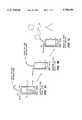
A second embodiment is described with reference to FIG. 3. This embodiment is similar to the first embodiment, and includes additional details.Tank 10 is where the carrier gas is bubbled through the liquid HMDS. The carrier gas is pressure regulated by regulator R1 and it is delivered totank 10 throughgas tube 12 which has an on/off control via valve V1. While, FIG. 3 shows regulator R1 as a mechanical operator-controlled device, regulator R1 can also be an electromechanical device controlled byprocessor 24 to approximately 5-15 pounds per square inch. A check valve V3 is included online 12 to ensure that no liquid HMDS can backflow if there are unexpected pressure situations. The carrier gas enterstank 10 viatube 12 into a "bubbler" B1 which is located near the bottom of thetank 10 and below the normal HMDS surface level.
The pressurization of the carrier gas causes it to "bubble" through "bubbler" B1 and then pass through the liquid HMDS. The carrier gas bubbles begin to become concentrated with HMDS as they rise through the HMDS liquid. When the carrier gas has completed its passage through the HMDS liquid, it accumulates at the top oftank 10 and then the concentrated carrier gas travels throughtube 14 to the integrated circuit fabrication process area where the HMDS concentrated carrier gas is used to cleanse the semiconductor wafers.
The HMDS surface level slowly falls as the carrier gas bubbles through the HMDS, becomes concentrated with HMDS and flows out throughtube 14. When the HMDS surface level falls belowoptimal level sensor 17, a fill sensor signal is sent toprocessor 24, which commandspump 26 to add HMDS totank 10. The additional HMDS intank 10 causes the liquid HMDS surface level to rise. When the HMDS surface level reachesoptimal level sensor 17, a full sensor signal is sent toprocessor 24 indicating that the HMDS surface level is satisfactory.Processor 24 responds to the full sensor signal by commandingpump 26 to halt. Additional level sensors such ashigh sensor 16 andlow sensor 18 are used to ensure safe operating conditions are maintained at all times. For example, these additional sensors detect overflow and low liquid conditions. Software inprocessor 24 is constructed to optimize the auto-leveling intank 10. Since the system is a positive feedback system,processor 24 takes into account that adjustments need time to settle and therefore acts slowly to perform the adjustments.
The processor generated command to operatepump 26 also includes associated commands to other valves that assist in the hydraulic and pneumatic functions ofpump 26.Pump 26 selected for this implementation uses a single diaphragm to move the liquid HMDS. The implementation illustrated uses a valve V5 to switch between air pressure and vacuum on a driving diaphragm D1. When air pressure is placed on diaphragm D1, the HMDS is forced intotank 10. When vacuum is drawn on diaphragm D1, HMDS is forced intopump 26 due to the atmospheric pressure on the HMDS liquidHMDS reserve tank 30. Additionally, pump 26 has an inlet valve V6 and an outlet valve V7. These valves are coordinated byprocessor 24 to ensure the flow of the liquid HMDS is from thereserve tank 30 totank 10. Valve V10 is used to control air flow through a venturi V11 which generates the necessary vacuum to drivepump 26.
The pumping function can be provided by other pump designs. The current implementation provides a high degree of control over the fluid flow and turbulence when refillingHMDS tank 10. A flow through sensor S4, detects whenHMDS reserve tank 30 of HMDS liquid. When this situation occurs, an electronic signal is sent toprocessor 24.Processor 24 then ensures thatpump 26 and its associated valves do not operate further since there is no more HMDS liquid to transport. Also,processor 24 generates an alarm to request thatHMDS reserve tank 30 is refilled by manual or automatic means.
Pneumatic circuits are installed to prevent over pressurization situations which could cause damage. Check valve V8 prevents excessive pressure from building up insidetank 10. Computer controlled valve V9 allows maintenance personnel to relieve pressure intank 10 when service is required. Pressure gauge G1 and pressure switch S2 provide visual and computer readable pressure status respectively.
An advantage of the invention includes a substantially constant HMDS level that in turn provides a substantially constant concentration of HMDS in the carrier gas which is delivered to the integrated circuit fabrication process. Additional advantages include increased integrated circuit fabrication up-time, reduced contamination and improved efficiency and continuity of the integrated circuit fabrication process. Moreover, the invention avoids human exposure to the HMDS.
Having disclosed exemplary embodiments and the best mode, modifications and variations may be made to the disclosed embodiments while remaining within the scope of the present invention as defined by the following claims.
Claims (20)
1. A tank apparatus for use in an integrated circuit fabrication process, comprising:
a tank configured to hold a liquid, said tank having a first inlet port configured to receive a carrier gas below a liquid surface level, an outlet port configured to release said carrier gas saturated with said liquid above said liquid surface level and a second inlet port configured to receive said liquid;
a sensor positioned in said tank at a predetermined liquid level and configured to generate a fill sensor signal when said liquid surface level falls below said predetermined liquid level; and
a processor coupled to said sensor and configured to generate a fill signal in response to said fill sensor signal to initiate introduction of said liquid into said tank through said second inlet port to maintain said liquid surface level at a substantially constant level and to provide a substantially constant path length for said carrier gas in said liquid in order to maintain a substantially constant concentration of said liquid in said carrier gas.
2. The tank apparatus of claim 1, wherein:
said sensor is configured to generate a full sensor signal when said liquid surface level rises above said predetermined liquid level; and
said processor is further configured to generate a halt signal in response to said full sensor signal to halt introduction of said liquid into said tank through said second inlet port.
3. The tank apparatus of claim 1, further comprising:
a low sensor positioned in said tank at a low liquid level and configured to generate an alarm signal when said liquid surface level falls below said low sensor.
4. The tank apparatus of claim 1, further comprising:
a high sensor positioned in said tank at a high liquid level and configured to generate an alarm signal when said liquid surface rises above said high sensor; and
wherein said processor is coupled to said high sensor and configured to generate a halt signal in response to said alarm signal to halt introduction of said liquid into said tank through said second inlet port.
5. The tank apparatus of claim 3, further comprising:
a high sensor positioned in said tank at a high liquid level and configured to generate a second alarm signal when said liquid surface rises above said high sensor; and
wherein said processor is coupled to said high sensor and configured to generate a halt signal in response to said second alarm signal to halt introduction of said liquid into said tank through said second inlet port.
6. The tank apparatus of claim 1, further comprising:
a liquid reserve tank configured to hold said liquid and having an outlet port; and
a pump coupled to said liquid reserve tank outlet port, to said tank apparatus second inlet port, and to said processor; and
wherein said processor is configured to activate said pump in response to said fill sensor signal.
7. The tank apparatus of claim 2, further comprising:
a liquid reserve tank configured to hold said liquid and having an outlet port; and
a pump coupled to said liquid reserve tank outlet port, to said tank apparatus second inlet port, and to said processor; and
wherein said processor is configured to activate said pump in response to said fill sensor signal and to halt said pump in response to said full sensor signal.
8. The tank apparatus of claim 3, further comprising:
a liquid reserve tank configured to hold said liquid and having an outlet port; and
a pump coupled to said liquid reserve tank outlet port, to said tank apparatus second inlet port, and to said processor; and
wherein said processor is configured to activate said pump in response to said fill sensor signal and to halt said pump in response to said full sensor signal.
9. The tank apparatus of claim 4, further comprising:
a liquid reserve tank configured to hold said liquid and having an outlet port; and
a pump coupled to said liquid reserve tank outlet port, to said tank apparatus second inlet port, and to said processor; and
wherein said processor is configured to activate said pump in response to said fill sensor signal and to halt said pump in response to said full sensor signal.
10. The tank apparatus of claim 5, further comprising:
a liquid reserve tank configured to hold said liquid and having an outlet port; and
a pump coupled to said liquid reserve tank outlet port, to said tank apparatus second inlet port, and to said processor; and
wherein said processor is configured to activate said pump in response to said fill sensor signal and to halt said pump in response to said full sensor signal.
11. The tank apparatus of claim 6, further comprising:
a regulator coupled to said processor and said first inlet port and configured to deliver said carrier gas to said tank at a regulated pressure; and
wherein said processor is configured to control said regulator to maintain a pressure range of said carrier gas in said tank of approximately 5 to 15 pounds per square inch.
12. The tank apparatus of claim 7, further comprising:
a regulator coupled to said processor and said first inlet port and configured to deliver said carrier gas to said tank at a regulated pressure; and
wherein said processor is configured to control said regulator to maintain a pressure range of said carrier gas in said tank of approximately 5 to 15 pounds per square inch.
13. The tank apparatus of claim 8, further comprising:
a regulator coupled to said processor and said first inlet port and configured to deliver said carrier gas to said tank at a regulated pressure; and
wherein said processor is configured to control said regulator to maintain a pressure range of said carrier gas in said tank of approximately 5 to 15 pounds per square inch.
14. The tank apparatus of claim 9, further comprising:
a regulator coupled to said processor and said first inlet port and configured to deliver said carrier gas to said tank at a regulated pressure; and
wherein said processor is configured to control said regulator to maintain a pressure range of said carrier gas in said tank of approximately 5 to 15 pounds per square inch.
15. The tank apparatus of claim 10, further comprising:
a regulator coupled to said processor and said first inlet port and configured to deliver said carrier gas to said tank at a regulated pressure; and
wherein said processor is configured to control said regulator to maintain a pressure range of said carrier gas in said tank of approximately 5 to 15 pounds per square inch.
16. The tank apparatus of claim 1, further comprising:
a liquid reserve tank configured to hold said liquid and having an outlet port; and
a fluid transfer structure coupled to said liquid reserve tank outlet port, to said tank apparatus second inlet port, and to said processor; and
wherein said processor is configured to activate said fluid transfer structure in response to said fill sensor signal.
17. The tank apparatus of claim 2, further comprising:
a liquid reserve tank configured to hold said liquid and having an outlet port; and
a fluid transfer structure coupled to said liquid reserve tank outlet port, to said tank apparatus second inlet port, and to said processor; and
wherein said processor is configured to activate said fluid transfer structure in response to said fill sensor signal.
18. The tank apparatus of claim 3, further comprising:
a liquid reserve tank configured to hold said liquid and having an outlet port; and
a fluid transfer structure coupled to said liquid reserve tank outlet port, to said tank apparatus second inlet port, and to said processor; and
wherein said processor is configured to activate said fluid transfer structure in response to said fill sensor signal.
19. The tank apparatus of claim 4, further comprising:
a liquid reserve tank configured to hold said liquid and having an outlet port; and
a fluid transfer structure coupled to said liquid reserve tank outlet port, to said tank apparatus second inlet port, and to said processor; and
wherein said processor is configured to activate said fluid transfer structure in response to said fill sensor signal.
20. The tank apparatus of claim 16, further comprising:
a regulator coupled to said processor and said first inlet port and configured to deliver said carrier gas to said tank at a regulated pressure; and
wherein said processor is configured to control said regulator to maintain a pressure range of said carrier gas in said tank of approximately 5 to 15 pounds per square inch.
Priority Applications (1)
| Application Number | Priority Date | Filing Date | Title |
|---|---|---|---|
| US08/577,560US5700401A (en) | 1995-12-22 | 1995-12-22 | Liquid auto-level apparatus and method |
Applications Claiming Priority (1)
| Application Number | Priority Date | Filing Date | Title |
|---|---|---|---|
| US08/577,560US5700401A (en) | 1995-12-22 | 1995-12-22 | Liquid auto-level apparatus and method |
Publications (1)
| Publication Number | Publication Date |
|---|---|
| US5700401Atrue US5700401A (en) | 1997-12-23 |
Family
ID=24309247
Family Applications (1)
| Application Number | Title | Priority Date | Filing Date |
|---|---|---|---|
| US08/577,560Expired - Fee RelatedUS5700401A (en) | 1995-12-22 | 1995-12-22 | Liquid auto-level apparatus and method |
Country Status (1)
| Country | Link |
|---|---|
| US (1) | US5700401A (en) |
Cited By (16)
| Publication number | Priority date | Publication date | Assignee | Title |
|---|---|---|---|---|
| US6098843A (en)* | 1998-12-31 | 2000-08-08 | Silicon Valley Group, Inc. | Chemical delivery systems and methods of delivery |
| US6145702A (en)* | 1999-10-05 | 2000-11-14 | Taiwan Semiconductor Manufacturing Co., Ltd. | Method and apparatus for adjusting minimum liquid level in a liquid supply bottle |
| US6206240B1 (en)* | 1999-03-23 | 2001-03-27 | Now Technologies, Inc. | Liquid chemical dispensing system with pressurization |
| US6269975B2 (en) | 1998-12-30 | 2001-08-07 | Semco Corporation | Chemical delivery systems and methods of delivery |
| US6276552B1 (en) | 1999-07-06 | 2001-08-21 | Steve Vervisch | Sealed container latch system |
| US6499961B1 (en) | 2000-03-16 | 2002-12-31 | Tecumseh Products Company | Solid state liquid level sensor and pump controller |
| US20030235389A1 (en)* | 2002-06-25 | 2003-12-25 | Gu-Young Kang | Raw material providing device for chemical vapor deposition process |
| US6692572B1 (en)* | 1999-09-13 | 2004-02-17 | Precision Valve & Automation, Inc. | Active compensation metering system |
| US20040041286A1 (en)* | 2002-08-30 | 2004-03-04 | Jai-Dong Lee | Method and apparatus for supplying a source gas |
| US20050103799A1 (en)* | 2003-10-15 | 2005-05-19 | Zavida Coffee Company Inc. | Fluid dispensing system suitable for dispensing liquid flavorings |
| US7007822B2 (en) | 1998-12-30 | 2006-03-07 | The Boc Group, Inc. | Chemical mix and delivery systems and methods thereof |
| US20070009365A1 (en)* | 2003-10-15 | 2007-01-11 | Zavida Coffee Company Inc. | Fluid dispensing system suitable for dispensing liquid flavorings |
| US20090178727A1 (en)* | 2008-01-14 | 2009-07-16 | Murphy Stephen A | Combination water conservation apparatus and watering bucket with method of use |
| US20090315197A1 (en)* | 2008-06-19 | 2009-12-24 | Hung-Liang Hsieh | Constant temperature gas/liquid mixture generating system for use in wafer drying process |
| US20130032217A1 (en)* | 2011-08-05 | 2013-02-07 | Thomas Pesek | Methods and apparatus for level loop control |
| CN107611055A (en)* | 2016-07-12 | 2018-01-19 | 沈阳芯源微电子设备有限公司 | A kind of pipeline liquid feed device for reducing bubble and producing and there is automatic row's bubble function |
Citations (18)
| Publication number | Priority date | Publication date | Assignee | Title |
|---|---|---|---|---|
| US3051192A (en)* | 1960-04-20 | 1962-08-28 | Us Rubber Co | Control system |
| US3322957A (en)* | 1963-12-20 | 1967-05-30 | Phillips Petroleum Co | Device with photoelectric failure alarm |
| US3876107A (en)* | 1971-04-30 | 1975-04-08 | Wienerberg Getranke Ges M B H | Process and apparatus for conveying liquids containing gases |
| US4014461A (en)* | 1976-03-10 | 1977-03-29 | The Coca-Cola Co. | Automatic change-over device for liquid dispensing system |
| DE2620117A1 (en)* | 1976-05-06 | 1977-11-24 | Leipold Dieter Dipl Braumstr | Liquid discharge system from containers - prevents oxygen absorption by vacuum responsive changeover of discharge valves |
| US4106671A (en)* | 1975-10-31 | 1978-08-15 | Beckman Instruments, Inc. | Liquid head control system |
| US4247018A (en)* | 1979-12-14 | 1981-01-27 | The Coca-Cola Company | Non-pressurized fluid transfer system |
| US4275823A (en)* | 1979-07-27 | 1981-06-30 | The Coca-Cola Company | Automatic change-over system for liquid dispensing system |
| US4319568A (en)* | 1979-10-29 | 1982-03-16 | Vickers Limited | Liquid dispensing apparatus |
| US4493435A (en)* | 1982-11-10 | 1985-01-15 | Product Research And Development | Liquid dispensing system and automatic selector therefor |
| US4560089A (en)* | 1981-05-11 | 1985-12-24 | The Cornelius Company | Apparatus for dispensing a carbonated beverage |
| US4601409A (en)* | 1984-11-19 | 1986-07-22 | Tritec Industries, Inc. | Liquid chemical dispensing system |
| US4728005A (en)* | 1984-03-19 | 1988-03-01 | Jet Spray Corp. | Self-fill system |
| US5293893A (en)* | 1993-01-27 | 1994-03-15 | Fsi International, Inc. | Empty drum detecting apparatus |
| US5316181A (en)* | 1990-01-29 | 1994-05-31 | Integrated Designs, Inc. | Liquid dispensing system |
| US5383574A (en)* | 1993-07-19 | 1995-01-24 | Microbar Sytems, Inc. | System and method for dispensing liquid from storage containers |
| US5405443A (en)* | 1992-04-24 | 1995-04-11 | Tokyo Electron Limited | Substrates processing device |
| US5480063A (en)* | 1993-03-05 | 1996-01-02 | Keyes; Denis E. | Volumetric fluid dispensing apparatus |
- 1995
- 1995-12-22USUS08/577,560patent/US5700401A/ennot_activeExpired - Fee Related
Patent Citations (18)
| Publication number | Priority date | Publication date | Assignee | Title |
|---|---|---|---|---|
| US3051192A (en)* | 1960-04-20 | 1962-08-28 | Us Rubber Co | Control system |
| US3322957A (en)* | 1963-12-20 | 1967-05-30 | Phillips Petroleum Co | Device with photoelectric failure alarm |
| US3876107A (en)* | 1971-04-30 | 1975-04-08 | Wienerberg Getranke Ges M B H | Process and apparatus for conveying liquids containing gases |
| US4106671A (en)* | 1975-10-31 | 1978-08-15 | Beckman Instruments, Inc. | Liquid head control system |
| US4014461A (en)* | 1976-03-10 | 1977-03-29 | The Coca-Cola Co. | Automatic change-over device for liquid dispensing system |
| DE2620117A1 (en)* | 1976-05-06 | 1977-11-24 | Leipold Dieter Dipl Braumstr | Liquid discharge system from containers - prevents oxygen absorption by vacuum responsive changeover of discharge valves |
| US4275823A (en)* | 1979-07-27 | 1981-06-30 | The Coca-Cola Company | Automatic change-over system for liquid dispensing system |
| US4319568A (en)* | 1979-10-29 | 1982-03-16 | Vickers Limited | Liquid dispensing apparatus |
| US4247018A (en)* | 1979-12-14 | 1981-01-27 | The Coca-Cola Company | Non-pressurized fluid transfer system |
| US4560089A (en)* | 1981-05-11 | 1985-12-24 | The Cornelius Company | Apparatus for dispensing a carbonated beverage |
| US4493435A (en)* | 1982-11-10 | 1985-01-15 | Product Research And Development | Liquid dispensing system and automatic selector therefor |
| US4728005A (en)* | 1984-03-19 | 1988-03-01 | Jet Spray Corp. | Self-fill system |
| US4601409A (en)* | 1984-11-19 | 1986-07-22 | Tritec Industries, Inc. | Liquid chemical dispensing system |
| US5316181A (en)* | 1990-01-29 | 1994-05-31 | Integrated Designs, Inc. | Liquid dispensing system |
| US5405443A (en)* | 1992-04-24 | 1995-04-11 | Tokyo Electron Limited | Substrates processing device |
| US5293893A (en)* | 1993-01-27 | 1994-03-15 | Fsi International, Inc. | Empty drum detecting apparatus |
| US5480063A (en)* | 1993-03-05 | 1996-01-02 | Keyes; Denis E. | Volumetric fluid dispensing apparatus |
| US5383574A (en)* | 1993-07-19 | 1995-01-24 | Microbar Sytems, Inc. | System and method for dispensing liquid from storage containers |
Cited By (24)
| Publication number | Priority date | Publication date | Assignee | Title |
|---|---|---|---|---|
| US6269975B2 (en) | 1998-12-30 | 2001-08-07 | Semco Corporation | Chemical delivery systems and methods of delivery |
| US6340098B2 (en) | 1998-12-30 | 2002-01-22 | Semco Corporation | Chemical delivery systems and methods of delivery |
| US7007822B2 (en) | 1998-12-30 | 2006-03-07 | The Boc Group, Inc. | Chemical mix and delivery systems and methods thereof |
| US6675987B2 (en) | 1998-12-30 | 2004-01-13 | The Boc Group, Inc. | Chemical delivery systems and methods of delivery |
| US6098843A (en)* | 1998-12-31 | 2000-08-08 | Silicon Valley Group, Inc. | Chemical delivery systems and methods of delivery |
| US6206240B1 (en)* | 1999-03-23 | 2001-03-27 | Now Technologies, Inc. | Liquid chemical dispensing system with pressurization |
| US6276552B1 (en) | 1999-07-06 | 2001-08-21 | Steve Vervisch | Sealed container latch system |
| US6692572B1 (en)* | 1999-09-13 | 2004-02-17 | Precision Valve & Automation, Inc. | Active compensation metering system |
| US6145702A (en)* | 1999-10-05 | 2000-11-14 | Taiwan Semiconductor Manufacturing Co., Ltd. | Method and apparatus for adjusting minimum liquid level in a liquid supply bottle |
| US6499961B1 (en) | 2000-03-16 | 2002-12-31 | Tecumseh Products Company | Solid state liquid level sensor and pump controller |
| US6978984B2 (en)* | 2002-06-25 | 2005-12-27 | Samsung Electronics Co., Ltd. | Raw material providing device for chemical vapor deposition process |
| US20030235389A1 (en)* | 2002-06-25 | 2003-12-25 | Gu-Young Kang | Raw material providing device for chemical vapor deposition process |
| US7007933B2 (en)* | 2002-08-30 | 2006-03-07 | Samsung Electronics Co., Ltd. | Method and apparatus for supplying a source gas |
| US20040041286A1 (en)* | 2002-08-30 | 2004-03-04 | Jai-Dong Lee | Method and apparatus for supplying a source gas |
| US7494028B2 (en)* | 2003-10-15 | 2009-02-24 | Zavida Coffee Company Inc. | Fluid dispensing system suitable for dispensing liquid flavorings |
| US20070009365A1 (en)* | 2003-10-15 | 2007-01-11 | Zavida Coffee Company Inc. | Fluid dispensing system suitable for dispensing liquid flavorings |
| US20090020553A1 (en)* | 2003-10-15 | 2009-01-22 | Charles Litterst | Fluid dispensing system suitable for dispensing liquid flavorings |
| US20050103799A1 (en)* | 2003-10-15 | 2005-05-19 | Zavida Coffee Company Inc. | Fluid dispensing system suitable for dispensing liquid flavorings |
| US7631788B2 (en) | 2003-10-15 | 2009-12-15 | Zavida Coffee Company Inc | Fluid dispensing system suitable for dispensing liquid flavorings |
| US7677412B2 (en) | 2003-10-15 | 2010-03-16 | Zavida Coffee Company Inc. | Fluid dispensing system suitable for dispensing liquid flavorings |
| US20090178727A1 (en)* | 2008-01-14 | 2009-07-16 | Murphy Stephen A | Combination water conservation apparatus and watering bucket with method of use |
| US20090315197A1 (en)* | 2008-06-19 | 2009-12-24 | Hung-Liang Hsieh | Constant temperature gas/liquid mixture generating system for use in wafer drying process |
| US20130032217A1 (en)* | 2011-08-05 | 2013-02-07 | Thomas Pesek | Methods and apparatus for level loop control |
| CN107611055A (en)* | 2016-07-12 | 2018-01-19 | 沈阳芯源微电子设备有限公司 | A kind of pipeline liquid feed device for reducing bubble and producing and there is automatic row's bubble function |
Similar Documents
| Publication | Publication Date | Title |
|---|---|---|
| US5700401A (en) | Liquid auto-level apparatus and method | |
| US20230384680A1 (en) | System and method for supplying and dispensing bubble-free photolithography chemical solutions | |
| US5636762A (en) | System and method for dispensing liquid from storage containers | |
| US4601409A (en) | Liquid chemical dispensing system | |
| US7685963B2 (en) | Method of and apparatus for dispensing photoresist in manufacturing semiconductor devices or the like | |
| US5316181A (en) | Liquid dispensing system | |
| TWI274039B (en) | Chemical mix and delivery systems and methods thereof | |
| US6019116A (en) | Liquid transfer system | |
| KR102639443B1 (en) | Gas dissolution liquid supply device and gas dissolution liquid supply method | |
| KR20010050311A (en) | Double pressure vessel chemical dispenser unit | |
| KR102408661B1 (en) | Apparatus for supplying treatment liquid | |
| JPH04132085U (en) | Liquid constant pressure supply device | |
| KR20020026154A (en) | Gas pressurized liquid pump with intermediate chamber | |
| JP2010186844A (en) | Processing liquid supply system and processing liquid supply method | |
| JP2008066520A (en) | Photoresist supply apparatus and photoresist supply method | |
| US11606935B2 (en) | Self-balancing poultry water distribution system | |
| KR20140096957A (en) | Automatic flushing system for toilet and electronic bidet toilet having the same | |
| JPH09129533A (en) | Chemicals automatic feeder in semiconductor manufacturing equipment | |
| JPH11121422A (en) | Chemical supply device | |
| CN114985149A (en) | Liquid supply system | |
| JPH04102600A (en) | Liquid transferring device | |
| KR20070076085A (en) | Chemical Supply System and Method | |
| JP2748664B2 (en) | Chemical treatment equipment | |
| WO2008139144A1 (en) | Anti-siphoning device | |
| KR100463745B1 (en) | High clean solution transfer and mixing device |
Legal Events
| Date | Code | Title | Description |
|---|---|---|---|
| FPAY | Fee payment | Year of fee payment:4 | |
| REMI | Maintenance fee reminder mailed | ||
| LAPS | Lapse for failure to pay maintenance fees | ||
| STCH | Information on status: patent discontinuation | Free format text:PATENT EXPIRED DUE TO NONPAYMENT OF MAINTENANCE FEES UNDER 37 CFR 1.362 | |
| FP | Lapsed due to failure to pay maintenance fee | Effective date:20051223 | |
| AS | Assignment | Owner name:SILICON VALLEY BANK, CALIFORNIA Free format text:SECURITY AGREEMENT;ASSIGNOR:INTEGRATED FLOW SYSTEMS LLC;REEL/FRAME:028497/0233 Effective date:20120703 | |
| AS | Assignment | Owner name:EAST WEST BANK, CALIFORNIA Free format text:SECURITY INTEREST;ASSIGNOR:INTEGRATED FLOW SYSTEMS, LLC;REEL/FRAME:034887/0951 Effective date:20150202 | |
| AS | Assignment | Owner name:INTEGRATED FLOW SYSTEMS, LLC, ARIZONA Free format text:TERMINATION AND RELEASE OF SECURITY INTEREST;ASSIGNOR:EAST WEST BANK;REEL/FRAME:047387/0537 Effective date:20180827 |