US5700244A - Fluid dispenser with fill adapter - Google Patents
Fluid dispenser with fill adapterDownload PDFInfo
- Publication number
- US5700244A US5700244AUS08/577,496US57749695AUS5700244AUS 5700244 AUS5700244 AUS 5700244AUS 57749695 AUS57749695 AUS 57749695AUS 5700244 AUS5700244 AUS 5700244A
- Authority
- US
- United States
- Prior art keywords
- fluid
- assembly
- container
- passageway
- housing
- Prior art date
- Legal status (The legal status is an assumption and is not a legal conclusion. Google has not performed a legal analysis and makes no representation as to the accuracy of the status listed.)
- Expired - Fee Related
Links
- 239000012530fluidSubstances0.000titleclaimsabstractdescription125
- 239000011521glassSubstances0.000claimsdescription6
- 238000004891communicationMethods0.000claimsdescription4
- 229920001971elastomerPolymers0.000claimsdescription4
- 238000002788crimpingMethods0.000claims1
- 239000000806elastomerSubstances0.000claims1
- 238000001802infusionMethods0.000abstractdescription9
- 230000013011matingEffects0.000abstractdescription4
- 230000001681protective effectEffects0.000abstractdescription2
- 239000000463materialSubstances0.000description17
- 239000012528membraneSubstances0.000description11
- 238000010276constructionMethods0.000description9
- 239000004033plasticSubstances0.000description8
- 229920003023plasticPolymers0.000description8
- 235000012431wafersNutrition0.000description7
- 239000007788liquidSubstances0.000description6
- 239000003814drugSubstances0.000description5
- 229920000515polycarbonatePolymers0.000description4
- 239000004417polycarbonateSubstances0.000description4
- 238000007789sealingMethods0.000description4
- 238000009826distributionMethods0.000description3
- 229910052751metalInorganic materials0.000description3
- 239000002184metalSubstances0.000description3
- 150000002739metalsChemical class0.000description3
- 238000005192partitionMethods0.000description3
- 229920001296polysiloxanePolymers0.000description3
- 239000005060rubberSubstances0.000description3
- 239000000126substanceSubstances0.000description3
- 229920000459Nitrile rubberPolymers0.000description2
- 238000004026adhesive bondingMethods0.000description2
- 238000013459approachMethods0.000description2
- 229920005549butyl rubberPolymers0.000description2
- 239000000919ceramicSubstances0.000description2
- 229920000126latexPolymers0.000description2
- 238000000034methodMethods0.000description2
- 238000012986modificationMethods0.000description2
- 230000004048modificationEffects0.000description2
- 229920002492poly(sulfone)Polymers0.000description2
- -1polypropylenePolymers0.000description2
- 239000005373porous glassSubstances0.000description2
- 239000011148porous materialSubstances0.000description2
- 238000013022ventingMethods0.000description2
- JOYRKODLDBILNP-UHFFFAOYSA-NEthyl urethaneChemical compoundCCOC(N)=OJOYRKODLDBILNP-UHFFFAOYSA-N0.000description1
- 244000043261Hevea brasiliensisSpecies0.000description1
- 239000004952PolyamideSubstances0.000description1
- 239000004698PolyethyleneSubstances0.000description1
- 239000004743PolypropyleneSubstances0.000description1
- 239000011149active materialSubstances0.000description1
- 230000002009allergenic effectEffects0.000description1
- 229910052782aluminiumInorganic materials0.000description1
- XAGFODPZIPBFFR-UHFFFAOYSA-NaluminiumChemical compound[Al]XAGFODPZIPBFFR-UHFFFAOYSA-N0.000description1
- 230000000712assemblyEffects0.000description1
- 238000000429assemblyMethods0.000description1
- 230000009286beneficial effectEffects0.000description1
- 239000011195cermetSubstances0.000description1
- 239000003795chemical substances by applicationSubstances0.000description1
- 229920001577copolymerPolymers0.000description1
- 238000013461designMethods0.000description1
- 229940079593drugDrugs0.000description1
- 238000005538encapsulationMethods0.000description1
- 239000010408filmSubstances0.000description1
- 239000007789gasSubstances0.000description1
- 229920001519homopolymerPolymers0.000description1
- 238000003780insertionMethods0.000description1
- 230000037431insertionEffects0.000description1
- 238000000608laser ablationMethods0.000description1
- 238000004519manufacturing processMethods0.000description1
- 239000000203mixtureSubstances0.000description1
- 229920003052natural elastomerPolymers0.000description1
- 229920001194natural rubberPolymers0.000description1
- 229920002647polyamidePolymers0.000description1
- 229920000728polyesterPolymers0.000description1
- 229920000573polyethylenePolymers0.000description1
- 229920001195polyisoprenePolymers0.000description1
- 229920000642polymerPolymers0.000description1
- 229920000098polyolefinPolymers0.000description1
- 229920001155polypropylenePolymers0.000description1
- 229920002635polyurethanePolymers0.000description1
- 239000004814polyurethaneSubstances0.000description1
- 229910001220stainless steelInorganic materials0.000description1
- 239000010935stainless steelSubstances0.000description1
- 229920003048styrene butadiene rubberPolymers0.000description1
- 239000010409thin filmSubstances0.000description1
Images


Classifications
- A—HUMAN NECESSITIES
- A61—MEDICAL OR VETERINARY SCIENCE; HYGIENE
- A61M—DEVICES FOR INTRODUCING MEDIA INTO, OR ONTO, THE BODY; DEVICES FOR TRANSDUCING BODY MEDIA OR FOR TAKING MEDIA FROM THE BODY; DEVICES FOR PRODUCING OR ENDING SLEEP OR STUPOR
- A61M5/00—Devices for bringing media into the body in a subcutaneous, intra-vascular or intramuscular way; Accessories therefor, e.g. filling or cleaning devices, arm-rests
- A61M5/14—Infusion devices, e.g. infusing by gravity; Blood infusion; Accessories therefor
- A61M5/142—Pressure infusion, e.g. using pumps
- A61M5/145—Pressure infusion, e.g. using pumps using pressurised reservoirs, e.g. pressurised by means of pistons
- A61M5/148—Pressure infusion, e.g. using pumps using pressurised reservoirs, e.g. pressurised by means of pistons flexible, e.g. independent bags
- A61M5/152—Pressure infusion, e.g. using pumps using pressurised reservoirs, e.g. pressurised by means of pistons flexible, e.g. independent bags pressurised by contraction of elastic reservoirs
- A—HUMAN NECESSITIES
- A61—MEDICAL OR VETERINARY SCIENCE; HYGIENE
- A61M—DEVICES FOR INTRODUCING MEDIA INTO, OR ONTO, THE BODY; DEVICES FOR TRANSDUCING BODY MEDIA OR FOR TAKING MEDIA FROM THE BODY; DEVICES FOR PRODUCING OR ENDING SLEEP OR STUPOR
- A61M5/00—Devices for bringing media into the body in a subcutaneous, intra-vascular or intramuscular way; Accessories therefor, e.g. filling or cleaning devices, arm-rests
- A61M5/14—Infusion devices, e.g. infusing by gravity; Blood infusion; Accessories therefor
- A61M5/1407—Infusion of two or more substances
- A61M5/1409—Infusion of two or more substances in series, e.g. first substance passing through container holding second substance, e.g. reconstitution systems
- A—HUMAN NECESSITIES
- A61—MEDICAL OR VETERINARY SCIENCE; HYGIENE
- A61M—DEVICES FOR INTRODUCING MEDIA INTO, OR ONTO, THE BODY; DEVICES FOR TRANSDUCING BODY MEDIA OR FOR TAKING MEDIA FROM THE BODY; DEVICES FOR PRODUCING OR ENDING SLEEP OR STUPOR
- A61M5/00—Devices for bringing media into the body in a subcutaneous, intra-vascular or intramuscular way; Accessories therefor, e.g. filling or cleaning devices, arm-rests
- A61M5/14—Infusion devices, e.g. infusing by gravity; Blood infusion; Accessories therefor
- A61M5/168—Means for controlling media flow to the body or for metering media to the body, e.g. drip meters, counters ; Monitoring media flow to the body
- A61M5/16804—Flow controllers
- A61M5/16827—Flow controllers controlling delivery of multiple fluids, e.g. sequencing, mixing or via separate flow-paths
Definitions
- the present inventionrelates generally to infusion devices. More particularly, the invention concerns an elastomeric bladder type infusion apparatus which is used for delivering a beneficial agent to a patient at a substantially constant rate.
- the apparatusuniquely includes a fluid dispensing assembly and a novel fill assembly which can be interconnected with the dispensing assembly for filling the fluid reservoir thereof in the field prior to use.
- U.S. Pat. No. 4,915,693 issued to Hesseldiscloses an infusion pump comprising an elastomeric bladder having at least an open end, and an elongate stress member extending concentrically within the entire length of the hollow portion of the bladder and having a fluid tight seal therewith. Both a filling port and an exit port are provided in the stress member, each in fluid communication with the interior of the bladder by way of an influent and an effluent lumen, respectively.
- the stress memberhas a diameter that is greater than the relaxed internal diameter of the bladder, and has a length that exceeds the relaxed internal length of the hollow portion of the bladder, so that it prestresses the bladder in both the axial and radial directions when disposed therein, substantially filling the bladder in its unfilled state.
- the Hessel devicealso includes a one-way valve on the stress member which permits flow in the influent lumen only in the direction of the interior of the bladder.
- the bladder membercomprises a balloon, or tube-like member which is typically distendable both lengthwise and laterally when initially pressured. Admission and discharge of liquid is of necessity, through a single neck, or outlet portion of the balloon-like bladder.
- the fill assembly of the present inventionincludes a fluid containing vial assembly mounted within a unique adapter assembly which functions to conveniently mate the vial assembly with the fluid dispenser portion of the apparatus to enable expeditious filling of the fluid reservoir thereof.
- Ser. No. 08/192,031describes in detail the construction of several types of elastomeric bladder stored energy type infusion devices of a character similar to the fluid dispenser portion of the apparatus described herein.
- the apparatus of the present inventioncomprises an improvement of these devices and accordingly application, Ser. No. 08/192,031, is hereby incorporated by reference in its entirety as though fully set forth herein.
- Another object of the present inventionis to provide an apparatus of the aforementioned character in which the fill assembly comprises a vial assembly of generally conventional construction that can be prefilled with a wide variety of medicinal fluids.
- Another object of the present inventionis to provide a fill assembly of the type described in the preceding paragraph in which the prefilled vial assembly is partially received within a novel adapter assembly that functions to operably couple the vial assembly with the fluid dispenser subassembly of the apparatus.
- Another object of the inventionis to provide an adapter assembly of the type described in which the body of the prefilled vial is surrounded by a protective covering until immediately prior to mating the assembly with the fluid delivery device.
- Another object of the inventionis to provide an apparatus as described in the preceding paragraphs in which the adapter assembly includes locking means for locking the assembly to the fluid delivery assembly following filling of the fluid reservoir thereof.
- Another object of the inventionis to provide a novel adapter assembly for use with the bladder type stored energy fluid dispenser subassembly of the apparatus which is easy to use, is inexpensive to manufacture, and one which maintains the prefilled vial in an aseptic condition until time of use.
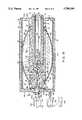
- FIG. 1is a generally perspective exploded view of one form of the fluid delivery apparatus of the present invention showing the fluid dispenser assembly and the fill assembly of the apparatus as they appear prior to mating the fill assembly with the dispenser assembly.
- FIG. 2is a generally perspective, exploded view of the apparatus shown in FIG. 1.
- FIG. 3is a right end view of the apparatus of FIG. 1.
- FIG. 4is an enlarged, cross-sectional view taken along lines 4--4 of FIG. 3.
- FIG. 5is a view, partly in cross section, taken along lines 5--5 of FIG. 4.
- FIG. 6is a generally perspective, exploded view of one form of the fill assembly of the present invention.
- FIG. 7is an enlarged cross-sectional view of the fill assembly illustrated in FIG. 6 as it appears in an assembled configuration.
- FIG. 8is a cross-sectional view similar to FIG. 7, but showing the appearance of the component parts of the invention after the plunger of the container has been telescopically moved from a first to a second position.
- FIG. 9is an enlarged, cross-sectional view taken along lines 9--9 of FIG. 7.
- FIG. 10is an enlarged, cross-sectional view of the adapter subassembly receiving chamber of an alternate form of the apparatus which embodies a blunt cannula rather than a needle type cannula and showing the adapter subassembly partially inserted into the receiving chamber.
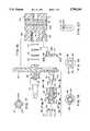
- FIG. 11is an exploded, cross-sectional view of an alternate form of the fluid dispenser assembly of the apparatus of the invention.
- FIG. 12is an enlarged view taken along lines 12--12 of FIG. 11.
- FIG. 13is an enlarged view taken along lines 13--13 of FIG. 11.
- FIG. 14is an enlarged view taken along lines 14--14 of FIG. 11.
- FIG. 15is an enlarged, cross-sectional view of the fully assembled dispenser portion of the apparatus shown in FIG. 11 operably coupled with the fill assembly of the apparatus of the invention.
- FIG. 16is an exploded, cross-sectional view of the forward portion of still another form of fluid dispenser assembly of the present invention.
- FIG. 17is a view taken along lines 17--17 of FIG. 16.
- FIG. 18is a view taken along lines 18--18 of FIG. 16.
- FIG. 19is a view taken along lines 19--19 of FIG. 16.
- FIG. 20is a view taken along lines 20--20 of FIG. 16.
- FIG. 21is a cross-sectional view of the forward portion of the fluid delivery assembly shown in FIG. 16 as it appears with the various components thereof assembled together.
- FIG. 22is a cross-sectional view taken along lines 22--22 of FIG. 21.
- Apparatus 10comprises two main assemblies, namely a fluid dispensing assembly 11 and a fill assembly 12 for use in filling the fluid reservoir of the dispensing assembly.
- Dispensing assembly 11the details of construction of which will presently be described, is similar in many respects to the dispenser described in Ser. No. 08/192,031 and includes a tubular support, a stored energy means for forming in conjunction with the support a fluid reservoir for containing medicinal fluids to be controllably infused into a patient and a generally cylindrically shaped housing which circumscribes the tubular support and stored energy means.
- the fill assembly portion 12 of the apparatuscomprises a container subassembly 14, an adapter subassembly 15, and a cover subassembly 17, the character of which will presently be described.
- Container subassembly 14includes a body portion 16, having a fluid chamber 18 for containing an injectable fluid "F" provided with first and second open ends 20 and 22 (FIGS. 7 and 8).
- First open end 20is sealably closed by closure means here provided in the form of a pierceable septum assembly 24. Septum assemby 24 is held securely in position by clamping ring 24a.
- closure meanshere provided in the form of a pierceable septum assembly 24. Septum assemby 24 is held securely in position by clamping ring 24a.
- a plunger 26is telescopically movable within chamber 18 of container subassembly 14 from a first location shown in FIG. 7 where it is proximate first open end 22 to a second position shown in FIG. 8 where it is proximate first open end 20.
- the vial portion of the container subassembly 14can be constructed of various materials such as glass and plastic.
- the adapter subassembly 15comprises a hollow housing 30 having a first open end 32 and a second closed end 34 (FIG. 8).
- Container subassembly 14is telescopically receivable within open end 32 of housing 30 in the manner shown in FIG. 7 so that the housing can be moved from the first extended position shown in FIG. 7 to the vial encapsulation position shown in FIG. 8.
- pusher meansshown here as an elongated pusher rod 36 which functions to move plunger 26 within fluid chamber 18 from the first position shown in FIG. 7 to the second position shown in FIG. 8.
- pusher rod 36has a first end 36a interconnected with closure wall 34 and an opposite end 36b which engages plunger 26 and causes telescopic movement of the plunger within chamber 18 of container subassembly 14 as housing 30 is moved from the extended position into the vial encapsulating position shown in FIG. 8.
- the interior wall 31 of housing 30is provided with circumferentially spaced-apart protuberances 40 which engage and center container subassembly 14 within housing 30. Due to the small surface area presented by protuberances 40, there is little frictional resistance to the sliding movement of container subassembly 14 relative to housing 30 as the housing is moved from the extended position shown in FIG. 7 into the vial encapsulating position shown in FIG. 8.
- cover subassembly 17 of the fill assembly of the present form of the inventionincludes a spiral wound, frangible portion 42 having a first open end 44 for telescopically receiving body portion 16 of container subassembly 14 (FIG. 7) and a second closed end 46.
- Portion 42initially circumscribes a major portion of container subassembly 14 in the manner best seen in FIG. 7.
- An integral pull tab 42ais provided to permit the spiral wound, frangible portion to be pulled from container subassembly 14 so as to expose a substantial portion of body 16. As best seen in FIG.
- a medicament label 50circumscribes spiral wound portion 42 and serves to prevent accidental unwinding of the spiral portion from the container subassembly 14. However, upon pulling tab 42a, the spiral portion will unwind and, in so doing, will tear medicament label 50 so that the spiral portion 42 of the covering as well as the cylindrical portion 52 which, also comprises a part of the cover assembly, can be slipped from the container 14 so as to expose to view septum assembly 24.
- venting apertures 54which are covered by a porous vent patch 56 which can be constructed from any suitable porous material that will permit air entrapped within the interior of subassembly cover subassembly 17 to be expelled to atmosphere as the subassembly is placed over container subassembly 14.
- the fluid dispensing assembly 11 of the apparatus of the inventioncan be seen to comprise an elongated housing 60 having an internal chamber 62 and a support 64 disposed within internal chamber 62 and extending longitudinally thereof.
- the stored energy means of the inventionis here provided in the form of a generally cylindrically shaped, elongated elastomeric member 66.
- Housing 60includes a generally cylindrically shaped central portion 60a and inlet and outlet end plates 60b and 60c respectively.
- Central section 60a and end plates 60b and 60cmay be constructed from any suitable rigid plastic material such as a polycarbonate and the end plates can be affixed to the central section by any suitable means such as adhesive bonding or an appropriate sonic weldment.
- Elastomeric member 66is securely affixed proximate its ends to a two-part support 64 (FIG. 4) by means of suitable ring clamps 68 and 70 such as self-locking plastic panduit strips of the character shown in FIG. 2.
- support 64is provided with an elongated receiving chamber 82 having an inner end wall portion 84 with supports a hollow piercing cannula 86 which extends into receiving chamber 82.
- Wall 84is provided with first and second radially extending fluid passageways 90 and 92.
- Passageway 90communicates proximate its central portion with the fluid passageway of hollow cannula 86 and communicates at its extremities with a fluid reservoir 94 formed between elastomeric member 66 and the outer central surface of support 64.
- passageway 92also communicate with fluid reservoir 94, while the center of the passageway communicates with a longitudinally extending outlet passageway 96, which, in turn, communicates with flow control means 97, the character of which will presently be described.
- End plate 60cis provided with an outlet passageway 100 which is in communication with the flow control means 97 and forms a part of luer connector like construction 102 which is integrally formed with end plate 60c.
- Filter member 110can be constructed from a wide variety of materials, but a material comprising polysulfone sold by Gelman Sciences under the name and style of SUPOR has proven satisfactory for the purpose.
- Rate control assemblage 112is preferably constructed from a porous material having small flow apertures which controllably impede fluid flow. However, a number of other materials can also be used to construct this permeable member including metals, ceramics, cermet, plastics and glass.
- the rate control membercan be specifically tailored to accommodate very specific very specific delivery regimes including very low flow and intermediate flow conditions. Such rate control assemblages are well known by those skilled in the art.
- the cover subassemblyis first removed from the container subassembly by pulling on pull-tab 42a. This will cause the spiral portion 42 of the cover subassembly to tear away from the container subassembly so that it can be separated from the forwardly disposed portion 52. Once the spiral wound portion 42 is removed, cylindrical portion 52 can also be removed and discarded. Removal of the cover subassembly exposes the forward portion of the container subassembly and readies the adapter subassembly for interconnection with the fluid dispensing assembly 11.
- Mating of the adapter subassembly 15 with the dispensing assembly 11is accomplished by telescopically inserting the exposed container portion of the container subassembly 14 into receiving chamber 82 and pushing the assemblage forwardly of housing 60.
- the piercing cannula 86 connected to end portion 64will pierce septum assembly 24 of the container subassembly.
- membrane 66can comprise a single film layer or can be made up of a laminate construction comprising of a number of cooperating layers of material.
- Materials suitable for constructing membrane 66include latex rubber, polyisoprene (natural rubber), butyl rubber, nitrile rubber, other homopolymer, copolymers (random, alternating, block, graft, crosslink and starblock), mechanical poly blends and interpenetrating polymer networks.
- Materials suitable for use in constructing housing 60 and support 64include metals, rubber or plastics that are compatible with the liquids they contact and are preferably non-allergenic type material. Examples of such materials are: stainless steel, aluminum, latex rubber, butyl rubber, nitrile rubber, polyisiprene, styrene-butadiene copolymer, silicones, polyolefins such as polypropylene and polyethylene, polyesters, polyurethane, polyamides and polycarbonates.
- Manufactures of suitable materials for use in constructing the fluid dispensing assembly of the inventioninclude: Dow Corning of Midland, Mich.; General Electric of Schenectady, N.Y.; and Shell Chemical Company of Houston, Tex.; DuPont Chemical of Wilmington, Del.; and Eastman Chemical of Kingsport, Tenn.
- novel locking meansare provided.
- the locking meanshere comprise a series of locking teeth 122 and 124 respectively. As indicated in FIG. 4, these locking teeth are constructed so that they will slide under a flexible locking tab 126, which is provided proximate the entrance of receiving chamber 82, as the adapter subassembly is urged inwardly of receiving chamber 82.
- locking tab 126will engage one of the teeth 124 and effectively prevent removal of housing 60 of the adapter subassembly from passageway 82.
- FIG. 10another form of the apparatus of the invention is there shown.
- This apparatusis similar in construction and operation to that shown in FIG. 1 through 9 save that the septum of container septum assembly, designated in FIG. 10 as 25, is a slit septum and the cannula, designated in FIG. 10 as 86a, is a blunt cannula configuration.
- Such constructionsare well known to those skilled in the art and can be used in lieu of conventional non-coring pierceable septums and sharp needles.
- the blunt cannula type device partially shown in FIG. 10operates in the same manner as the apparatus of FIGS. 1 through 9.
- FIGS. 11 through 15still another embodiment of the present invention is there illustrated.
- This embodimentis also similar in many respects to the embodiment shown in FIGS. 1 through 9 and, accordingly, like numbers have been used to identify like components.
- the primary difference between this latest form of the invention and that previously described hereinis the provision of an alternate fill means for filling the reservoir of the device.
- Forming a part of this novel alternate fill meansare strategically located valve means which are disposed within the dispensing assembly for controlling fluid flow through the apparatus.
- this novel valve meanspermits the inclusion of a fill line 211, which forms a part of the alternate fill means, and a fluid delivery line each of which communicates with the reservoir of the device.
- the fluid dispensing assembly of this latest form of the inventioncan be seen to comprise an elongated housing 60 having an internal chamber 62 and a two-part support 154 disposed within internal chamber 62 and extending longitudinally thereof.
- the stored energy means of the inventionis here provided in the form of a generally cylindrically shaped, elongated elastomeric member 66 of identical construction to that previously described.
- Housing 60comprises a cylindrically shaped central portion 60a and inlet and outlet end plates 60b and 156 respectively.
- Central section 60a and end plates 60b and 156may be constructed from any suitable rigid plastic material such as a polycarbonate and the end plates can be affixed to the central section by any suitable means such as adhesive bonding or an appropriate sonic weldment.
- end plate 60bis provided with a vent port "V" for venting gases within the housing to atmosphere.
- Elastomeric member 66is securely affixed proximate its ends to support 154 by means of suitable ring clamps 68 and 70 such as self-locking plastic panduit strips.
- support 154is formed by a forward section 154a and a rearward section 154b which is integrally formed with end plate 60b.
- Support 154is provided with an elongated receiving chamber 157 having an inner end wall portion 158 which is provided with a central counterbore 160 (FIG. 11).
- Wall 158is also provided with first and second radially extending fluid passageways 162 and 164.
- Passageway 162communicates proximate its central portion with counterbore 160 and communicates at its end portions with a fluid reservoir 167 (FIG. 15) formed between elastomeric member 66 and the outer central surface of support 154.
- end wall or partition 158 of support 154is also provided with a pair of radially spaced, longitudinally extending fluid passageways 176 and 178.
- the inboard end of each of these passagewayscommunicates with reservoir 167 while the outboard ends thereof communicate with novel flow control means for controlling fluid flow outwardly of passageways 176.
- This flow control meanshere comprises an annular shaped filter 180 and an annular shaped rate control member 182.
- Member 182overlays a generally annular shaped chamber 187 formed in end plate 156, which chamber, in a manner presently to be described, communicates with the fluid outlet port of the apparatus via bore 191.
- annular chamber 187includes a multiplicity of microchannels and grooves 187a which direct the flow of fluid toward an outlet passageway 186 formed in end plate 156 (see also FIG. 11).
- Outlet passageway 186communicates with a fluid delivery tube 190 one end of which is received within a bore 191 formed in end plate 156.
- the opposite end of tube 190is connected to a conventional luer fitting 192.
- a female luer cap 192a(FIG. 15) is mateable with fitting 192 to block fluid flow outwardly of delivery tube 190.
- a second check valve meanscontrols fluid flow between passageway 172 and passageway 168.
- This second valve meanswhich forms a part of the alternate fill means, comprises a valve member 200 which includes a body portion 200a, a neck portion 200b and an intermediate tapered shoulder 200c.
- Check valve member 200can be constructed from rubber, silicone, urethane and like materials.
- a filling line assembly 210which includes a fill line 211, is connected to luer like connector 174 so that fluid under pressure can be introduced into passageway 172.
- This fluid under pressurewill move valve 200 member inwardly causing shoulder 200c to move away from seat 207 thereby permitting fluid to flow past valve member body 200a, through a plurality of circumferentially spaced channels 209 formed in end plate 156 (see FIGS. 11 and 13). Fluid will then flow into inlet passageway 168 to passageway 164 to either fill or partially fill the reservoir 167.
- a dilluentcould be introduced into reservoir 167 via the filling line assembly 210 and an injectable drug could be introduced into the reservoir using fill assembly 12.
- the cover subassemblyis, as before, removed from the container subassembly by pulling on pull-tab 42a and the adapter subassembly is then telescopically inserted into receiving chamber 157 in the manner shown in FIG. 15.
- valve meansWith the valve means open, the fluid will flow into passageway 162 of partition wall 158 and then into fluid reservoir 167. As the fluid under pressure flows into reservoir 167, membrane 66 will be distended outwardly in the manner shown in FIG. 15 wherein the central portion thereof is spaced from support 154. It is to be noted that at the commencement of the fluid delivery step, spring 204 will urge valve element 201 into sealing engagement with seat 197 thereby maintaining reservoir 167 in a filled condition.
- locking meansincluding a flexible locking tab 154c, is provided on support 154 to engage locking teeth 122 and 124 provided on adapter 15 in order to lock the adapter in position within housing 150 after the filling step has been completed.
- a medicament label "L"surrounds housing 150 to identify the medicament contained within the reservoir 167.
- distendable membrane 66Once distendable membrane 66 is distended to form fluid reservoir 167, the apparatus will remain in this filled condition until the outlet passageway of the fitting 192 is opened by the removal of female luer 192a (FIG. 15). With the outlet passageway thus opened, the stored energy means or membrane 66 will tend to return to a less distended condition causing fluid to flow outwardly of the apparatus via passageway 176 and 178, through the flow control means 97, into annular chamber 187, and then outwardly through passageway 186 and into delivery tube 190.
- FIGS. 16 through 22yet another embodiment of the present invention is there illustrated.
- This embodimentis similar in many respects to the embodiment shown in. FIGS. 1 through 9 and, accordingly like numbers have been used to identify like components.
- the primary difference between this last form of the invention and that of FIGS. 1 through 9is the design of the outlet, or forward portion of the dispensing assembly. More particularly, as best seen in FIG. 21, this form of the invention includes alternate fill means for filling the fluid reservoir of the device.
- This alternate fill meansincludes a radially offset inlet, part of which includes check valve means for controlling fluid flow toward the reservoir 94 of the device.
- This check valve meansis housed within a chamber 248 formed in the inboard end of a luer like connector 250 which is connected to an end plate 252 and comprises a valve member 254 having a body portion 254a, a neck portion 254b and an intermediate shoulder portion 254c.
- Chamber 248communicates via passageway 255a of manifold element 255 (FIGS. 16 and 21) with an inlet passageway 256 which is formed in end wall 260a of support 260 and which, in turn, communicates with reservoir 94 via annular passageway 256a.
- Central support 160which is virtually identical to support 64 of the embodiment shown in FIG.
- an outlet passageway 263interconnects the flow control means with an outlet luer like connector 265 which forms an integral part of end plate 252.
- Connector 265is designed to receive a closure cap 267 which functions to block fluid flow through passageway 263.
- inlet luer connector 250is designed to lockably mate with a locking fill cap 270.
- Cap 270includes circumferentially spaced locking fins 270a which lockably mate with circumferentially spaced fins 270e provided on fitting 250 (FIGS. 16, 17, and 21). With this arrangement, once cap 270 is connected to fitting 250, it will be securely locked in place thereon and sealably close the inlet passageway thereof.
- the flow control means of the present form of the inventioncomprises an assemblage made up of four disc-like wafers which are mounted within a rate control chamber 271 formed in end wall 260 of central support 260.
- Wafers 272 and 274 of the assemblagecomprise porous glass distribution frits while intermediate wafer 276 comprises a filter member and intermediate wafer 278 comprises a rate control member.
- Filter member 276can be constructed from a wide variety of materials, but a material comprising polysulfone sold by Gelman Sciences under the name and style of SUPOR has proven satisfactory for the purpose.
- Rate control member 278is preferably constructed from a thin film, polycarbonate material having extremely small flow apertures ablatively drilled by an excimer laser ablation process. Both the orifice size and unit distribution can be closely controlled by this process. However, a number of other materials can also be used to construct this permeable member including metals, ceramics, plastics and glass.
- the rate control C membercan be specifically tailored to accommodate various delivery regimens including low flow and intermediate flow conditions.
- the apparatus of this last form of the inventionis used in the same general manner as previously described to fill reservoir 94 either by means of the fill assembly or by means of the fill port or luer like fitting 250.
- fluidis introduced into passageway 256 by exertion of fluid pressure on valve member 254 sufficient to move shoulder 254c away from seat 250a of fitting 250 so that fluid can flow past valve member body 254a, passageway 255a of manifold element 255, and through a plurality of circumferentially spaced channels 280 formed in fitting 250 through chamber 248, into passageway 255a of manifold 255 and then into passageway 256 (FIG. 19).
- Cap 270includes circumferentially spaced locking fins 270a which lockably mate with circumferentially spaced fins 270-l provided on fitting 250.
- the fill assemblyis mated with the fluid delivery assembly in the same manner as previously described, herein in connection with the embodiments of FIGS. 1 through 15.
Landscapes
- Health & Medical Sciences (AREA)
- Vascular Medicine (AREA)
- Engineering & Computer Science (AREA)
- Anesthesiology (AREA)
- Biomedical Technology (AREA)
- Heart & Thoracic Surgery (AREA)
- Hematology (AREA)
- Life Sciences & Earth Sciences (AREA)
- Animal Behavior & Ethology (AREA)
- General Health & Medical Sciences (AREA)
- Public Health (AREA)
- Veterinary Medicine (AREA)
- Infusion, Injection, And Reservoir Apparatuses (AREA)
- Containers And Packaging Bodies Having A Special Means To Remove Contents (AREA)
Abstract
Description
Claims (15)
Priority Applications (13)
| Application Number | Priority Date | Filing Date | Title |
|---|---|---|---|
| US08/577,496US5700244A (en) | 1992-04-17 | 1995-12-22 | Fluid dispenser with fill adapter |
| US08/729,326US5873857A (en) | 1992-04-17 | 1996-10-15 | Fluid dispenser with fill adapter |
| CA002241152ACA2241152A1 (en) | 1995-12-22 | 1996-12-23 | Fluid dispenser with fill adapter |
| EP96943817AEP0874649A4 (en) | 1995-12-22 | 1996-12-23 | Fluid dispenser with fill adapter |
| BR9612777-5ABR9612777A (en) | 1995-12-22 | 1996-12-23 | Fluid dispenser with filling adaptation |
| JP09523821AJP2000517201A (en) | 1995-12-22 | 1996-12-23 | Fluid dispenser with filling adapter |
| CN96199965ACN1209071A (en) | 1995-12-22 | 1996-12-23 | Fluid dispenser with infusion adapter |
| AU12954/97AAU707017B2 (en) | 1995-12-22 | 1996-12-23 | Fluid dispenser with fill adapter |
| PCT/US1996/020324WO1997023250A1 (en) | 1995-12-22 | 1996-12-23 | Fluid dispenser with fill adapter |
| US09/165,709US5980489A (en) | 1992-04-17 | 1998-10-02 | Fluid dispenser with fill adapter |
| US09/250,040US6086560A (en) | 1992-04-17 | 1999-02-12 | Fluid dispenser with fill adapter |
| US09/329,840US6090071A (en) | 1992-04-17 | 1999-06-10 | Fluid dispenser with fill adapter |
| US09/561,786US6245041B1 (en) | 1992-04-17 | 2000-05-01 | Fluid dispenser with fill adapter |
Applications Claiming Priority (5)
| Application Number | Priority Date | Filing Date | Title |
|---|---|---|---|
| US07/870,521US5263940A (en) | 1992-04-17 | 1992-04-17 | Fluid dispenser |
| US08/053,723US5354278A (en) | 1992-04-17 | 1993-04-26 | Fluid dispenser |
| US08/156,685US5433709A (en) | 1992-04-17 | 1993-11-22 | Fluid dispensing apparatus including mounting base for a plurality of fluid dispensing devices |
| US08/192,031US5484415A (en) | 1992-04-17 | 1994-02-03 | Fluid dispensing apparatus |
| US08/577,496US5700244A (en) | 1992-04-17 | 1995-12-22 | Fluid dispenser with fill adapter |
Related Parent Applications (1)
| Application Number | Title | Priority Date | Filing Date |
|---|---|---|---|
| US08/192,031Continuation-In-PartUS5484415A (en) | 1992-04-17 | 1994-02-03 | Fluid dispensing apparatus |
Related Child Applications (1)
| Application Number | Title | Priority Date | Filing Date |
|---|---|---|---|
| US08/729,326Continuation-In-PartUS5873857A (en) | 1992-04-17 | 1996-10-15 | Fluid dispenser with fill adapter |
Publications (1)
| Publication Number | Publication Date |
|---|---|
| US5700244Atrue US5700244A (en) | 1997-12-23 |
Family
ID=24308980
Family Applications (1)
| Application Number | Title | Priority Date | Filing Date |
|---|---|---|---|
| US08/577,496Expired - Fee RelatedUS5700244A (en) | 1992-04-17 | 1995-12-22 | Fluid dispenser with fill adapter |
Country Status (8)
| Country | Link |
|---|---|
| US (1) | US5700244A (en) |
| EP (1) | EP0874649A4 (en) |
| JP (1) | JP2000517201A (en) |
| CN (1) | CN1209071A (en) |
| AU (1) | AU707017B2 (en) |
| BR (1) | BR9612777A (en) |
| CA (1) | CA2241152A1 (en) |
| WO (1) | WO1997023250A1 (en) |
Cited By (36)
| Publication number | Priority date | Publication date | Assignee | Title |
|---|---|---|---|---|
| US5957895A (en) | 1998-02-20 | 1999-09-28 | Becton Dickinson And Company | Low-profile automatic injection device with self-emptying reservoir |
| WO1999052579A1 (en) | 1998-04-15 | 1999-10-21 | Science Incorporated | Fluid dispenser with reservoir fill assembly |
| US6086560A (en)* | 1992-04-17 | 2000-07-11 | Science Incorporated | Fluid dispenser with fill adapter |
| US6126642A (en)* | 1998-10-02 | 2000-10-03 | Science Incorporated | Patient controlled fluid delivery device |
| US6139535A (en)* | 1999-05-27 | 2000-10-31 | Situs Corporation | Method and apparatus for placement and activation of a medical device within a body cavity |
| WO2000069509A1 (en)* | 1999-05-14 | 2000-11-23 | Science Incorporated | Fluid delivery device with fill adapter |
| US6183461B1 (en) | 1998-03-11 | 2001-02-06 | Situs Corporation | Method for delivering a medication |
| US6186982B1 (en)* | 1998-05-05 | 2001-02-13 | Elan Corporation, Plc | Subcutaneous drug delivery device with improved filling system |
| WO2005016406A3 (en)* | 2003-08-05 | 2006-02-16 | Marshall S Kriesel | Infusion apparatus with modulated flow control |
| US20060116647A1 (en)* | 2000-09-19 | 2006-06-01 | Simone Geiser | Device for administering a injectable product in doses |
| US20080009835A1 (en)* | 2005-02-17 | 2008-01-10 | Kriesel Marshall S | Fluid dispensing apparatus with flow rate control |
| US7530968B2 (en) | 2003-04-23 | 2009-05-12 | Valeritas, Inc. | Hydraulically actuated pump for long duration medicament administration |
| US20100049135A1 (en)* | 1998-10-29 | 2010-02-25 | Medtronic Minimed, Inc. | Reservoir connector |
| US20100168675A1 (en)* | 2005-10-25 | 2010-07-01 | Becton, Dickinson And Company | One piece low drag septum |
| US7914499B2 (en) | 2006-03-30 | 2011-03-29 | Valeritas, Inc. | Multi-cartridge fluid delivery device |
| US20120150139A1 (en)* | 2008-12-12 | 2012-06-14 | Roche Diagnostics International Ag | System For Ambulatory Drug Infusion Comprising A Filling Apparatus For Flexible Containers, Container Assembly, And Use Of A Flexible Container |
| US8287495B2 (en) | 2009-07-30 | 2012-10-16 | Tandem Diabetes Care, Inc. | Infusion pump system with disposable cartridge having pressure venting and pressure feedback |
| US9089636B2 (en) | 2004-07-02 | 2015-07-28 | Valeritas, Inc. | Methods and devices for delivering GLP-1 and uses thereof |
| US9555186B2 (en) | 2012-06-05 | 2017-01-31 | Tandem Diabetes Care, Inc. | Infusion pump system with disposable cartridge having pressure venting and pressure feedback |
| US9962486B2 (en) | 2013-03-14 | 2018-05-08 | Tandem Diabetes Care, Inc. | System and method for detecting occlusions in an infusion pump |
| USD819802S1 (en) | 2016-10-05 | 2018-06-05 | Becton, Dickinson And Company | Catheter adapter |
| USD835262S1 (en) | 2016-10-05 | 2018-12-04 | Becton, Dickinson And Company | Intravenous catheter assembly |
| USD837368S1 (en) | 2016-10-05 | 2019-01-01 | Becton, Dickinson And Company | Catheter adapter grip |
| US20190016484A1 (en)* | 2017-07-12 | 2019-01-17 | Vanrx Pharmasystems Inc. | Purgeable pharmaceutical fill needle |
| US10238852B2 (en) | 2016-10-05 | 2019-03-26 | Becton, Dickinson And Company | Septum housing |
| USD844781S1 (en) | 2016-10-05 | 2019-04-02 | Becton, Dickinson And Company | Needle hub |
| US10245416B2 (en) | 2015-10-28 | 2019-04-02 | Becton, Dickinson And Company | Intravenous catheter device with integrated extension tube |
| US10258736B2 (en) | 2012-05-17 | 2019-04-16 | Tandem Diabetes Care, Inc. | Systems including vial adapter for fluid transfer |
| US10357636B2 (en) | 2015-10-28 | 2019-07-23 | Becton, Dickinson And Company | IV access device having an angled paddle grip |
| US10525237B2 (en) | 2015-10-28 | 2020-01-07 | Becton, Dickinson And Company | Ergonomic IV systems and methods |
| US10549072B2 (en) | 2015-10-28 | 2020-02-04 | Becton, Dickinson And Company | Integrated catheter with independent fluid paths |
| US10639455B2 (en) | 2015-10-28 | 2020-05-05 | Becton, Dickinson And Company | Closed IV access device with paddle grip needle hub and flash chamber |
| US10744305B2 (en) | 2015-10-28 | 2020-08-18 | Becton, Dickinson And Company | Ergonomic IV systems and methods |
| US10814106B2 (en) | 2015-10-28 | 2020-10-27 | Becton, Dickinson And Company | Soft push tabs for catheter adapter |
| USD907193S1 (en) | 2018-02-21 | 2021-01-05 | Eli Lilly And Company | Secured medication transfer set |
| US11730678B2 (en) | 2016-08-22 | 2023-08-22 | Eli Lilly And Company | Secured medication transfer system |
Families Citing this family (3)
| Publication number | Priority date | Publication date | Assignee | Title |
|---|---|---|---|---|
| US5957891A (en)* | 1995-10-11 | 1999-09-28 | Science Incorporated | Fluid delivery device with fill adapter |
| ES2728054T3 (en)* | 2013-06-18 | 2019-10-22 | Enable Injections Inc | Vial transfer and injection device |
| CN106031805A (en)* | 2015-03-11 | 2016-10-19 | 李荣辉 | An elastic infusion device and a method for manufacturing the same |
Citations (29)
| Publication number | Priority date | Publication date | Assignee | Title |
|---|---|---|---|---|
| US3136313A (en)* | 1954-10-27 | 1964-06-09 | Astra Ab | Automatic hypodermic syringe |
| US3828779A (en)* | 1972-12-13 | 1974-08-13 | Ims Ltd | Flex-o-jet |
| US3993069A (en)* | 1973-03-26 | 1976-11-23 | Alza Corporation | Liquid delivery device bladder |
| US4180070A (en)* | 1977-08-29 | 1979-12-25 | Abbott Laboratories | Disposable double vial syringe |
| US4578060A (en)* | 1983-07-20 | 1986-03-25 | Howmedica, Inc. | Wound drainage device |
| US4883483A (en)* | 1985-11-13 | 1989-11-28 | Advanced Medical Technologies Inc. | Medicine vial adaptor for needleless injector |
| US4886495A (en)* | 1987-07-08 | 1989-12-12 | Duoject Medical Systems Inc. | Vial-based prefilled syringe system for one or two component medicaments |
| US4915693A (en)* | 1986-11-26 | 1990-04-10 | Baxter International, Inc. | Pressurized fluid dispenser |
| US4919657A (en)* | 1988-11-14 | 1990-04-24 | Habley Medical Technology Corporation | Dental syringe having a medication filled carpule and a retractable needle cannula |
| US4983164A (en)* | 1987-04-14 | 1991-01-08 | Astra Meditec Ab | Automatic two-chamber injector |
| US5011477A (en)* | 1989-04-21 | 1991-04-30 | Baxter International Inc. | Continuous/bolus infusor |
| US5067948A (en)* | 1990-09-27 | 1991-11-26 | Habley Medical Technology Corporation | Safety, packaging, injection and disposal system for pre-filled pharmaceutical vials |
| US5112307A (en)* | 1990-04-24 | 1992-05-12 | Habley Medical Technology Corp. | Dental syringe having a medication filled carpule and an automatically-detaching piston stem |
| US5135498A (en)* | 1990-04-02 | 1992-08-04 | Kam Robert J | Controlled release infusion device |
| US5171214A (en)* | 1990-12-26 | 1992-12-15 | Abbott Laboratories | Drug storage and delivery system |
| US5304165A (en)* | 1991-12-09 | 1994-04-19 | Habley Medical Technology Corporation | Syringe-filling medication dispenser |
| US5334162A (en)* | 1993-03-15 | 1994-08-02 | Eli Lilly And Company | Cartridge assembly for a lyophilized compound forming a disposable portion of an injector pen and method for same |
| US5336188A (en)* | 1989-06-16 | 1994-08-09 | Science Incorporated | Fluid delivery apparatus having a stored energy source |
| US5336180A (en)* | 1990-04-24 | 1994-08-09 | Science Incorporated | Closed drug delivery system |
| US5364386A (en)* | 1993-05-05 | 1994-11-15 | Hikari Seiyaku Kabushiki Kaisha | Infusion unit |
| US5374256A (en)* | 1989-06-16 | 1994-12-20 | Science Incorporated | Fluid container for use with a fluid delivery apparatus |
| US5397303A (en)* | 1993-08-06 | 1995-03-14 | River Medical, Inc. | Liquid delivery device having a vial attachment or adapter incorporated therein |
| US5411480A (en)* | 1989-06-16 | 1995-05-02 | Science Incorporated | Fluid delivery apparatus |
| US5451214A (en)* | 1993-03-22 | 1995-09-19 | Hajishoreh; Kaveh-Karimi | Syringe apparatus |
| US5454793A (en)* | 1992-01-22 | 1995-10-03 | Pharmacia Aktiebolag | Medicine dispensing device |
| US5462535A (en)* | 1991-07-12 | 1995-10-31 | Novo Nordisk A/S | Syringe system |
| US5466220A (en)* | 1994-03-08 | 1995-11-14 | Bioject, Inc. | Drug vial mixing and transfer device |
| US5472422A (en)* | 1992-07-07 | 1995-12-05 | Pharmacia Aktiebolag | Dual-chamber injection cartridge |
| US5484406A (en)* | 1992-11-19 | 1996-01-16 | Baxter International Inc. | In-line drug delivery device for use with a standard IV administration set and a method for delivery |
Family Cites Families (2)
| Publication number | Priority date | Publication date | Assignee | Title |
|---|---|---|---|---|
| GB8630016D0 (en)* | 1986-12-16 | 1987-01-28 | Id Tech Ltd | Dental injection device |
| US5354278A (en)* | 1992-04-17 | 1994-10-11 | Science Incorporated | Fluid dispenser |
- 1995
- 1995-12-22USUS08/577,496patent/US5700244A/ennot_activeExpired - Fee Related
- 1996
- 1996-12-23EPEP96943817Apatent/EP0874649A4/ennot_activeWithdrawn
- 1996-12-23CNCN96199965Apatent/CN1209071A/enactivePending
- 1996-12-23WOPCT/US1996/020324patent/WO1997023250A1/ennot_activeApplication Discontinuation
- 1996-12-23CACA002241152Apatent/CA2241152A1/ennot_activeAbandoned
- 1996-12-23AUAU12954/97Apatent/AU707017B2/ennot_activeCeased
- 1996-12-23BRBR9612777-5Apatent/BR9612777A/enunknown
- 1996-12-23JPJP09523821Apatent/JP2000517201A/enactivePending
Patent Citations (31)
| Publication number | Priority date | Publication date | Assignee | Title |
|---|---|---|---|---|
| US3136313A (en)* | 1954-10-27 | 1964-06-09 | Astra Ab | Automatic hypodermic syringe |
| US3828779A (en)* | 1972-12-13 | 1974-08-13 | Ims Ltd | Flex-o-jet |
| US3993069A (en)* | 1973-03-26 | 1976-11-23 | Alza Corporation | Liquid delivery device bladder |
| US4180070A (en)* | 1977-08-29 | 1979-12-25 | Abbott Laboratories | Disposable double vial syringe |
| US4578060A (en)* | 1983-07-20 | 1986-03-25 | Howmedica, Inc. | Wound drainage device |
| US4883483A (en)* | 1985-11-13 | 1989-11-28 | Advanced Medical Technologies Inc. | Medicine vial adaptor for needleless injector |
| US4915693A (en)* | 1986-11-26 | 1990-04-10 | Baxter International, Inc. | Pressurized fluid dispenser |
| US4983164A (en)* | 1987-04-14 | 1991-01-08 | Astra Meditec Ab | Automatic two-chamber injector |
| US5137511A (en)* | 1987-07-08 | 1992-08-11 | Duoject Medical Systems Inc. | Syringe |
| US4886495A (en)* | 1987-07-08 | 1989-12-12 | Duoject Medical Systems Inc. | Vial-based prefilled syringe system for one or two component medicaments |
| US4919657A (en)* | 1988-11-14 | 1990-04-24 | Habley Medical Technology Corporation | Dental syringe having a medication filled carpule and a retractable needle cannula |
| US5011477A (en)* | 1989-04-21 | 1991-04-30 | Baxter International Inc. | Continuous/bolus infusor |
| US5336188A (en)* | 1989-06-16 | 1994-08-09 | Science Incorporated | Fluid delivery apparatus having a stored energy source |
| US5411480A (en)* | 1989-06-16 | 1995-05-02 | Science Incorporated | Fluid delivery apparatus |
| US5374256A (en)* | 1989-06-16 | 1994-12-20 | Science Incorporated | Fluid container for use with a fluid delivery apparatus |
| US5135498A (en)* | 1990-04-02 | 1992-08-04 | Kam Robert J | Controlled release infusion device |
| US5336180A (en)* | 1990-04-24 | 1994-08-09 | Science Incorporated | Closed drug delivery system |
| US5112307A (en)* | 1990-04-24 | 1992-05-12 | Habley Medical Technology Corp. | Dental syringe having a medication filled carpule and an automatically-detaching piston stem |
| US5067948A (en)* | 1990-09-27 | 1991-11-26 | Habley Medical Technology Corporation | Safety, packaging, injection and disposal system for pre-filled pharmaceutical vials |
| US5171214A (en)* | 1990-12-26 | 1992-12-15 | Abbott Laboratories | Drug storage and delivery system |
| US5462535A (en)* | 1991-07-12 | 1995-10-31 | Novo Nordisk A/S | Syringe system |
| US5462535B1 (en)* | 1991-07-12 | 1996-12-31 | Novo Nordisk As | Syringe system |
| US5304165A (en)* | 1991-12-09 | 1994-04-19 | Habley Medical Technology Corporation | Syringe-filling medication dispenser |
| US5454793A (en)* | 1992-01-22 | 1995-10-03 | Pharmacia Aktiebolag | Medicine dispensing device |
| US5472422A (en)* | 1992-07-07 | 1995-12-05 | Pharmacia Aktiebolag | Dual-chamber injection cartridge |
| US5484406A (en)* | 1992-11-19 | 1996-01-16 | Baxter International Inc. | In-line drug delivery device for use with a standard IV administration set and a method for delivery |
| US5334162A (en)* | 1993-03-15 | 1994-08-02 | Eli Lilly And Company | Cartridge assembly for a lyophilized compound forming a disposable portion of an injector pen and method for same |
| US5451214A (en)* | 1993-03-22 | 1995-09-19 | Hajishoreh; Kaveh-Karimi | Syringe apparatus |
| US5364386A (en)* | 1993-05-05 | 1994-11-15 | Hikari Seiyaku Kabushiki Kaisha | Infusion unit |
| US5397303A (en)* | 1993-08-06 | 1995-03-14 | River Medical, Inc. | Liquid delivery device having a vial attachment or adapter incorporated therein |
| US5466220A (en)* | 1994-03-08 | 1995-11-14 | Bioject, Inc. | Drug vial mixing and transfer device |
Cited By (77)
| Publication number | Priority date | Publication date | Assignee | Title |
|---|---|---|---|---|
| US6086560A (en)* | 1992-04-17 | 2000-07-11 | Science Incorporated | Fluid dispenser with fill adapter |
| US6277095B1 (en)* | 1995-10-11 | 2001-08-21 | Science Incorporated | Fluid delivery device with full adapter |
| US5957895A (en) | 1998-02-20 | 1999-09-28 | Becton Dickinson And Company | Low-profile automatic injection device with self-emptying reservoir |
| US6183461B1 (en) | 1998-03-11 | 2001-02-06 | Situs Corporation | Method for delivering a medication |
| WO1999052579A1 (en) | 1998-04-15 | 1999-10-21 | Science Incorporated | Fluid dispenser with reservoir fill assembly |
| US5993425A (en)* | 1998-04-15 | 1999-11-30 | Science Incorporated | Fluid dispenser with reservoir fill assembly |
| US6186982B1 (en)* | 1998-05-05 | 2001-02-13 | Elan Corporation, Plc | Subcutaneous drug delivery device with improved filling system |
| US6126642A (en)* | 1998-10-02 | 2000-10-03 | Science Incorporated | Patient controlled fluid delivery device |
| US20100049135A1 (en)* | 1998-10-29 | 2010-02-25 | Medtronic Minimed, Inc. | Reservoir connector |
| US7998131B2 (en)* | 1998-10-29 | 2011-08-16 | Medtronic Minimed, Inc. | Reservoir connector |
| WO2000047269A1 (en)* | 1999-02-12 | 2000-08-17 | Science Incorporated | Fluid dispenser with fill adapter |
| WO2000069509A1 (en)* | 1999-05-14 | 2000-11-23 | Science Incorporated | Fluid delivery device with fill adapter |
| US6139535A (en)* | 1999-05-27 | 2000-10-31 | Situs Corporation | Method and apparatus for placement and activation of a medical device within a body cavity |
| US20060116647A1 (en)* | 2000-09-19 | 2006-06-01 | Simone Geiser | Device for administering a injectable product in doses |
| US7731698B2 (en)* | 2000-09-19 | 2010-06-08 | Tecpharma Licensing Ag | Device for administering an injectable product in doses |
| US7530968B2 (en) | 2003-04-23 | 2009-05-12 | Valeritas, Inc. | Hydraulically actuated pump for long duration medicament administration |
| US10525194B2 (en) | 2003-04-23 | 2020-01-07 | Valeritas, Inc. | Hydraulically actuated pump for fluid administration |
| US9511187B2 (en) | 2003-04-23 | 2016-12-06 | Valeritas, Inc. | Hydraulically actuated pump for fluid administration |
| US9072828B2 (en) | 2003-04-23 | 2015-07-07 | Valeritas, Inc. | Hydraulically actuated pump for long duration medicament administration |
| US9125983B2 (en) | 2003-04-23 | 2015-09-08 | Valeritas, Inc. | Hydraulically actuated pump for fluid administration |
| US8070726B2 (en) | 2003-04-23 | 2011-12-06 | Valeritas, Inc. | Hydraulically actuated pump for long duration medicament administration |
| US11642456B2 (en) | 2003-04-23 | 2023-05-09 | Mannkind Corporation | Hydraulically actuated pump for fluid administration |
| WO2005016406A3 (en)* | 2003-08-05 | 2006-02-16 | Marshall S Kriesel | Infusion apparatus with modulated flow control |
| US9089636B2 (en) | 2004-07-02 | 2015-07-28 | Valeritas, Inc. | Methods and devices for delivering GLP-1 and uses thereof |
| US20080009835A1 (en)* | 2005-02-17 | 2008-01-10 | Kriesel Marshall S | Fluid dispensing apparatus with flow rate control |
| US8066675B2 (en)* | 2005-10-25 | 2011-11-29 | Becton, Dickinson And Company | One piece low drag septum |
| US20100168675A1 (en)* | 2005-10-25 | 2010-07-01 | Becton, Dickinson And Company | One piece low drag septum |
| US9687599B2 (en) | 2006-03-30 | 2017-06-27 | Valeritas, Inc. | Multi-cartridge fluid delivery device |
| US8361053B2 (en) | 2006-03-30 | 2013-01-29 | Valeritas, Inc. | Multi-cartridge fluid delivery device |
| US8821443B2 (en) | 2006-03-30 | 2014-09-02 | Valeritas, Inc. | Multi-cartridge fluid delivery device |
| US10493199B2 (en) | 2006-03-30 | 2019-12-03 | Valeritas, Inc. | Multi-cartridge fluid delivery device |
| US12246159B2 (en) | 2006-03-30 | 2025-03-11 | Mannkind Corporation | Multi-cartridge fluid delivery device |
| US7914499B2 (en) | 2006-03-30 | 2011-03-29 | Valeritas, Inc. | Multi-cartridge fluid delivery device |
| US8827976B2 (en)* | 2008-12-12 | 2014-09-09 | Roche Diagnostics International Ag | System for ambulatory drug infusion comprising a filling apparatus for flexible containers, container assembly, and use of a flexible container |
| US20120150139A1 (en)* | 2008-12-12 | 2012-06-14 | Roche Diagnostics International Ag | System For Ambulatory Drug Infusion Comprising A Filling Apparatus For Flexible Containers, Container Assembly, And Use Of A Flexible Container |
| US8926561B2 (en) | 2009-07-30 | 2015-01-06 | Tandem Diabetes Care, Inc. | Infusion pump system with disposable cartridge having pressure venting and pressure feedback |
| US9211377B2 (en) | 2009-07-30 | 2015-12-15 | Tandem Diabetes Care, Inc. | Infusion pump system with disposable cartridge having pressure venting and pressure feedback |
| US11285263B2 (en) | 2009-07-30 | 2022-03-29 | Tandem Diabetes Care, Inc. | Infusion pump systems and methods |
| US11135362B2 (en) | 2009-07-30 | 2021-10-05 | Tandem Diabetes Care, Inc. | Infusion pump systems and methods |
| US8287495B2 (en) | 2009-07-30 | 2012-10-16 | Tandem Diabetes Care, Inc. | Infusion pump system with disposable cartridge having pressure venting and pressure feedback |
| US8298184B2 (en) | 2009-07-30 | 2012-10-30 | Tandem Diabetes Care, Inc. | Infusion pump system with disposable cartridge having pressure venting and pressure feedback |
| US12144964B2 (en) | 2009-07-30 | 2024-11-19 | Tandem Diabetes Care, Inc | Infusion pump system with disposable cartridge having pressure venting and pressure feedback |
| US12042627B2 (en) | 2009-07-30 | 2024-07-23 | Tandem Diabetes Care, Inc. | Infusion pump systems and methods |
| US8758323B2 (en) | 2009-07-30 | 2014-06-24 | Tandem Diabetes Care, Inc. | Infusion pump system with disposable cartridge having pressure venting and pressure feedback |
| US10258736B2 (en) | 2012-05-17 | 2019-04-16 | Tandem Diabetes Care, Inc. | Systems including vial adapter for fluid transfer |
| US9555186B2 (en) | 2012-06-05 | 2017-01-31 | Tandem Diabetes Care, Inc. | Infusion pump system with disposable cartridge having pressure venting and pressure feedback |
| US9962486B2 (en) | 2013-03-14 | 2018-05-08 | Tandem Diabetes Care, Inc. | System and method for detecting occlusions in an infusion pump |
| US12194254B2 (en) | 2015-10-28 | 2025-01-14 | Becton, Dickinson And Company | Intravenous catheter device with integrated extension tube |
| US10245416B2 (en) | 2015-10-28 | 2019-04-02 | Becton, Dickinson And Company | Intravenous catheter device with integrated extension tube |
| US10357636B2 (en) | 2015-10-28 | 2019-07-23 | Becton, Dickinson And Company | IV access device having an angled paddle grip |
| US10549072B2 (en) | 2015-10-28 | 2020-02-04 | Becton, Dickinson And Company | Integrated catheter with independent fluid paths |
| US10639455B2 (en) | 2015-10-28 | 2020-05-05 | Becton, Dickinson And Company | Closed IV access device with paddle grip needle hub and flash chamber |
| US12076509B2 (en) | 2015-10-28 | 2024-09-03 | Becton, Dickinson And Company | Integrated catheter with independent fluid paths |
| US10744305B2 (en) | 2015-10-28 | 2020-08-18 | Becton, Dickinson And Company | Ergonomic IV systems and methods |
| US10525237B2 (en) | 2015-10-28 | 2020-01-07 | Becton, Dickinson And Company | Ergonomic IV systems and methods |
| US10814106B2 (en) | 2015-10-28 | 2020-10-27 | Becton, Dickinson And Company | Soft push tabs for catheter adapter |
| US11964117B2 (en) | 2015-10-28 | 2024-04-23 | Becton, Dickinson And Company | Soft push tabs for catheter adapter |
| US11786703B2 (en) | 2015-10-28 | 2023-10-17 | Becton, Dickinson And Company | Closed IV access device with paddle grip needle hub and flash chamber |
| US11571551B2 (en) | 2015-10-28 | 2023-02-07 | Becton, Dickinson And Company | Ergonomic IV systems and methods |
| US11123523B2 (en) | 2015-10-28 | 2021-09-21 | Becton, Dickinson And Company | Intravenous catheter device with integrated extension tube |
| US12257405B2 (en) | 2015-10-28 | 2025-03-25 | Becton, Dickinson And Company | Ergonomic IV systems and methods |
| US12336966B2 (en) | 2016-08-22 | 2025-06-24 | Eli Lilly And Company | Secured medication transfer system |
| US11730678B2 (en) | 2016-08-22 | 2023-08-22 | Eli Lilly And Company | Secured medication transfer system |
| USD819802S1 (en) | 2016-10-05 | 2018-06-05 | Becton, Dickinson And Company | Catheter adapter |
| US10238852B2 (en) | 2016-10-05 | 2019-03-26 | Becton, Dickinson And Company | Septum housing |
| USD835262S1 (en) | 2016-10-05 | 2018-12-04 | Becton, Dickinson And Company | Intravenous catheter assembly |
| USD837368S1 (en) | 2016-10-05 | 2019-01-01 | Becton, Dickinson And Company | Catheter adapter grip |
| USD844781S1 (en) | 2016-10-05 | 2019-04-02 | Becton, Dickinson And Company | Needle hub |
| US11793986B2 (en) | 2016-10-05 | 2023-10-24 | Becton, Dickinson And Company | Septum housing |
| USD900308S1 (en) | 2016-10-05 | 2020-10-27 | Becton, Dickinson And Company | Catheter adapter |
| USD893707S1 (en) | 2016-10-05 | 2020-08-18 | Becton, Dickinson And Company | Intravenous catheter assembly |
| USD888236S1 (en) | 2016-10-05 | 2020-06-23 | Becton, Dickinson And Company | Catheter adapter grip |
| US20190016484A1 (en)* | 2017-07-12 | 2019-01-17 | Vanrx Pharmasystems Inc. | Purgeable pharmaceutical fill needle |
| US11014696B2 (en)* | 2017-07-12 | 2021-05-25 | Vanrx Pharmasystems Inc. | Purgeable pharmaceutical fill needle |
| USD907193S1 (en) | 2018-02-21 | 2021-01-05 | Eli Lilly And Company | Secured medication transfer set |
| USD990659S1 (en) | 2018-02-21 | 2023-06-27 | Eli Lilly And Company | Needle hub |
| USD997341S1 (en) | 2018-02-21 | 2023-08-29 | Eli Lilly And Company | Secured medication transfer set |
Also Published As
| Publication number | Publication date |
|---|---|
| BR9612777A (en) | 2001-09-04 |
| AU707017B2 (en) | 1999-07-01 |
| EP0874649A1 (en) | 1998-11-04 |
| AU1295497A (en) | 1997-07-17 |
| JP2000517201A (en) | 2000-12-26 |
| CN1209071A (en) | 1999-02-24 |
| CA2241152A1 (en) | 1997-07-03 |
| EP0874649A4 (en) | 2000-02-09 |
| WO1997023250A1 (en) | 1997-07-03 |
Similar Documents
| Publication | Publication Date | Title |
|---|---|---|
| US5700244A (en) | Fluid dispenser with fill adapter | |
| US5873857A (en) | Fluid dispenser with fill adapter | |
| US5993425A (en) | Fluid dispenser with reservoir fill assembly | |
| US5807335A (en) | Fluid delivery device with conformable ullage and fill assembly | |
| US6159180A (en) | Fluid delivery apparatus with flow indicator and vial fill | |
| US5741242A (en) | Infusion device with fill assembly | |
| EP3294374B1 (en) | Priming apparatus and method | |
| CA1165199A (en) | Medical infusor | |
| US6245041B1 (en) | Fluid dispenser with fill adapter | |
| US5779676A (en) | Fluid delivery device with bolus injection site | |
| US5419771A (en) | Fluid delivery apparatus and support assembly | |
| US6027472A (en) | Mixing and delivery syringe assembly | |
| US5962794A (en) | Fluid delivery apparatus with reservior fill assembly | |
| CA2241365A1 (en) | Fluid delivery device with conformable ullage and fill assembly | |
| EP0768901A1 (en) | Fluid delivery apparatus | |
| US6391006B1 (en) | Fluid delivery apparatus with reservoir fill assembly | |
| WO1995000190A1 (en) | Liquid delivery apparatus | |
| US5484415A (en) | Fluid dispensing apparatus | |
| US6086560A (en) | Fluid dispenser with fill adapter | |
| EP1007144A1 (en) | Fluid delivery apparatus | |
| MXPA98005082A (en) | Infusion device with fill unit |
Legal Events
| Date | Code | Title | Description |
|---|---|---|---|
| AS | Assignment | Owner name:SCIENCE INCORPORATED, CALIFORNIA Free format text:ASSIGNMENT OF ASSIGNORS INTEREST;ASSIGNOR:KRIESEL, MARSHALL S.;REEL/FRAME:008597/0303 Effective date:19970624 | |
| FPAY | Fee payment | Year of fee payment:4 | |
| AS | Assignment | Owner name:ARLEEN M. CARLSON 2000 BCG CLAT C/O MR. JOHN K. FL Free format text:SECURITY INTEREST;ASSIGNOR:SCIENCE INCORPORATED;REEL/FRAME:013258/0828 Effective date:20011120 Owner name:ARLEEN M. CARLSON 2000 MCN CLAT C/O MR. JOHN K. FL Free format text:SECURITY INTEREST;ASSIGNOR:SCIENCE INCORPORATED;REEL/FRAME:013258/0828 Effective date:20011120 Owner name:BRATTAIN, DONALD, MINNESOTA Free format text:SECURITY INTEREST;ASSIGNOR:SCIENCE INCORPORATED;REEL/FRAME:013258/0828 Effective date:20011120 Owner name:EVERS, MICHAEL J., MINNESOTA Free format text:SECURITY INTEREST;ASSIGNOR:SCIENCE INCORPORATED;REEL/FRAME:013258/0828 Effective date:20011120 Owner name:FARLEY, WILLIAM F., D/B/A LIVINGSTON CAPITAL, MINN Free format text:SECURITY INTEREST;ASSIGNOR:SCIENCE INCORPORATED;REEL/FRAME:013258/0828 Effective date:20011120 Owner name:GROSSMAN INVESTMENTS, ATTN: LARRY WALLER, MINNESOT Free format text:SECURITY INTEREST;ASSIGNOR:SCIENCE INCORPORATED;REEL/FRAME:013258/0828 Effective date:20011120 Owner name:HODDER, WILLIAM A., MINNESOTA Free format text:SECURITY INTEREST;ASSIGNOR:SCIENCE INCORPORATED;REEL/FRAME:013258/0828 Effective date:20011120 Owner name:LUECK, BRUCE C., MINNESOTA Free format text:SECURITY INTEREST;ASSIGNOR:SCIENCE INCORPORATED;REEL/FRAME:013258/0828 Effective date:20011120 Owner name:MCGLYNN, BURTON J., FLORIDA Free format text:SECURITY INTEREST;ASSIGNOR:SCIENCE INCORPORATED;REEL/FRAME:013258/0828 Effective date:20011120 Owner name:OKABENA PARTNERSHIP V-8, BRUCE C. LUECK, PRESIDENT Free format text:SECURITY INTEREST;ASSIGNOR:SCIENCE INCORPORATED;REEL/FRAME:013258/0828 Effective date:20011120 Owner name:POCKET, A NOMINE PARTNERSHIP C/O MR. RANDALL J. SU Free format text:SECURITY INTEREST;ASSIGNOR:SCIENCE INCORPORATED;REEL/FRAME:013258/0828 Effective date:20011120 Owner name:REVOCABLE TRUST OF BARBARA C. GAGE, C/O MR. JOHN K Free format text:SECURITY INTEREST;ASSIGNOR:SCIENCE INCORPORATED;REEL/FRAME:013258/0828 Effective date:20011120 Owner name:REVOCABLE TRUST OF EDWIN C. GAGE C/O MR. JOHN K. F Free format text:SECURITY INTEREST;ASSIGNOR:SCIENCE INCORPORATED;REEL/FRAME:013258/0828 Effective date:20011120 Owner name:SIT INVESTMENT ASSOCIATES, INC., EUGENE C. SIT, MI Free format text:SECURITY INTEREST;ASSIGNOR:SCIENCE INCORPORATED;REEL/FRAME:013258/0828 Effective date:20011120 Owner name:TORGERSON, PAUL M., MINNESOTA Free format text:SECURITY INTEREST;ASSIGNOR:SCIENCE INCORPORATED;REEL/FRAME:013258/0828 Effective date:20011120 Owner name:WALLIN FAMILY FOUNDATION, WINSTON R. WALLIN, MINNE Free format text:SECURITY INTEREST;ASSIGNOR:SCIENCE INCORPORATED;REEL/FRAME:013258/0828 Effective date:20011120 | |
| REMI | Maintenance fee reminder mailed | ||
| LAPS | Lapse for failure to pay maintenance fees | ||
| STCH | Information on status: patent discontinuation | Free format text:PATENT EXPIRED DUE TO NONPAYMENT OF MAINTENANCE FEES UNDER 37 CFR 1.362 | |
| FP | Expired due to failure to pay maintenance fee | Effective date:20051223 | |
| AS | Assignment | Owner name:SCIENCE INCORPORATED, MINNESOTA Free format text:RELEASE OF SECURITY AGREEMENT;ASSIGNORS:OKABENA PARTNERSIP V-8 BY OKABENA INVESTMENT SERVICES, INC. MANAGER;WINSTON R. WALLIN/WALLIN FAMILY FOUNDATION;WILLIAM F. FARLEY D/B/A LIVINGSTON CAPITAL;AND OTHERS;REEL/FRAME:019704/0733 Effective date:20070628 Owner name:PESCADERO BEACH HOLDINGS CORPORATION, CALIFORNIA Free format text:ASSIGNMENT OF ASSIGNORS INTEREST;ASSIGNOR:SCIENCO INCORPORATED;REEL/FRAME:019733/0235 Effective date:20070710 | |
| AS | Assignment | Owner name:PESCADERO BEACH HOLDINGS CORPORATION, CALIFORNIA Free format text:ASSIGNMENT OF ASSIGNORS INTEREST;ASSIGNOR:SCIENCE INCORPORATED;REEL/FRAME:019733/0298 Effective date:20070710 |