US5699414A - Method and apparatus for sharing a single telephone line between a facsimile machine, data modem, telephone answering device, and a person - Google Patents
Method and apparatus for sharing a single telephone line between a facsimile machine, data modem, telephone answering device, and a personDownload PDFInfo
- Publication number
- US5699414A US5699414AUS08/667,918US66791896AUS5699414AUS 5699414 AUS5699414 AUS 5699414AUS 66791896 AUS66791896 AUS 66791896AUS 5699414 AUS5699414 AUS 5699414A
- Authority
- US
- United States
- Prior art keywords
- call
- modem
- telephone
- facsimile machine
- facsimile
- Prior art date
- Legal status (The legal status is an assumption and is not a legal conclusion. Google has not performed a legal analysis and makes no representation as to the accuracy of the status listed.)
- Expired - Fee Related
Links
Images


Classifications
- H—ELECTRICITY
- H04—ELECTRIC COMMUNICATION TECHNIQUE
- H04N—PICTORIAL COMMUNICATION, e.g. TELEVISION
- H04N1/00—Scanning, transmission or reproduction of documents or the like, e.g. facsimile transmission; Details thereof
- H04N1/32—Circuits or arrangements for control or supervision between transmitter and receiver or between image input and image output device, e.g. between a still-image camera and its memory or between a still-image camera and a printer device
- H04N1/327—Initiating, continuing or ending a single-mode communication; Handshaking therefor
- H04N1/32704—Establishing a communication with one of a facsimile and another telecommunication apparatus sharing a single line
- H04N1/32706—Type of the other apparatus
- H04N1/32708—Telephone
- H—ELECTRICITY
- H04—ELECTRIC COMMUNICATION TECHNIQUE
- H04M—TELEPHONIC COMMUNICATION
- H04M1/00—Substation equipment, e.g. for use by subscribers
- H04M1/64—Automatic arrangements for answering calls; Automatic arrangements for recording messages for absent subscribers; Arrangements for recording conversations
- H04M1/65—Recording arrangements for recording a message from the calling party
- H04M1/654—Telephone line monitoring circuits therefor, e.g. ring detectors
- H—ELECTRICITY
- H04—ELECTRIC COMMUNICATION TECHNIQUE
- H04M—TELEPHONIC COMMUNICATION
- H04M1/00—Substation equipment, e.g. for use by subscribers
- H04M1/82—Line monitoring circuits for call progress or status discrimination
- H—ELECTRICITY
- H04—ELECTRIC COMMUNICATION TECHNIQUE
- H04M—TELEPHONIC COMMUNICATION
- H04M11/00—Telephonic communication systems specially adapted for combination with other electrical systems
- H04M11/06—Simultaneous speech and data transmission, e.g. telegraphic transmission over the same conductors
- H—ELECTRICITY
- H04—ELECTRIC COMMUNICATION TECHNIQUE
- H04N—PICTORIAL COMMUNICATION, e.g. TELEVISION
- H04N1/00—Scanning, transmission or reproduction of documents or the like, e.g. facsimile transmission; Details thereof
- H04N1/32—Circuits or arrangements for control or supervision between transmitter and receiver or between image input and image output device, e.g. between a still-image camera and its memory or between a still-image camera and a printer device
- H04N1/327—Initiating, continuing or ending a single-mode communication; Handshaking therefor
- H04N1/32704—Establishing a communication with one of a facsimile and another telecommunication apparatus sharing a single line
- H04N1/32706—Type of the other apparatus
- H04N1/3271—Telephone answering machine
- H—ELECTRICITY
- H04—ELECTRIC COMMUNICATION TECHNIQUE
- H04N—PICTORIAL COMMUNICATION, e.g. TELEVISION
- H04N1/00—Scanning, transmission or reproduction of documents or the like, e.g. facsimile transmission; Details thereof
- H04N1/32—Circuits or arrangements for control or supervision between transmitter and receiver or between image input and image output device, e.g. between a still-image camera and its memory or between a still-image camera and a printer device
- H04N1/327—Initiating, continuing or ending a single-mode communication; Handshaking therefor
- H04N1/32704—Establishing a communication with one of a facsimile and another telecommunication apparatus sharing a single line
- H04N1/32706—Type of the other apparatus
- H04N1/32713—Data transmission device, e.g. switched network of teleprinters for the distribution of text-based information transceiver
- H—ELECTRICITY
- H04—ELECTRIC COMMUNICATION TECHNIQUE
- H04N—PICTORIAL COMMUNICATION, e.g. TELEVISION
- H04N1/00—Scanning, transmission or reproduction of documents or the like, e.g. facsimile transmission; Details thereof
- H04N1/32—Circuits or arrangements for control or supervision between transmitter and receiver or between image input and image output device, e.g. between a still-image camera and its memory or between a still-image camera and a printer device
- H04N1/327—Initiating, continuing or ending a single-mode communication; Handshaking therefor
- H04N1/32704—Establishing a communication with one of a facsimile and another telecommunication apparatus sharing a single line
- H04N1/32715—Detecting
- H04N1/32717—Detecting a calling tone, e.g. CI
- H—ELECTRICITY
- H04—ELECTRIC COMMUNICATION TECHNIQUE
- H04N—PICTORIAL COMMUNICATION, e.g. TELEVISION
- H04N1/00—Scanning, transmission or reproduction of documents or the like, e.g. facsimile transmission; Details thereof
- H04N1/32—Circuits or arrangements for control or supervision between transmitter and receiver or between image input and image output device, e.g. between a still-image camera and its memory or between a still-image camera and a printer device
- H04N1/327—Initiating, continuing or ending a single-mode communication; Handshaking therefor
- H04N1/32704—Establishing a communication with one of a facsimile and another telecommunication apparatus sharing a single line
- H04N1/32715—Detecting
- H04N1/32719—Detecting a facsimile calling signal, e.g. CNG
- H—ELECTRICITY
- H04—ELECTRIC COMMUNICATION TECHNIQUE
- H04N—PICTORIAL COMMUNICATION, e.g. TELEVISION
- H04N1/00—Scanning, transmission or reproduction of documents or the like, e.g. facsimile transmission; Details thereof
- H04N1/32—Circuits or arrangements for control or supervision between transmitter and receiver or between image input and image output device, e.g. between a still-image camera and its memory or between a still-image camera and a printer device
- H04N1/327—Initiating, continuing or ending a single-mode communication; Handshaking therefor
- H04N1/32704—Establishing a communication with one of a facsimile and another telecommunication apparatus sharing a single line
- H04N1/32715—Detecting
- H04N1/32726—Detecting signals other than facsimile protocol signals, e.g. DTMF signals
- H—ELECTRICITY
- H04—ELECTRIC COMMUNICATION TECHNIQUE
- H04N—PICTORIAL COMMUNICATION, e.g. TELEVISION
- H04N1/00—Scanning, transmission or reproduction of documents or the like, e.g. facsimile transmission; Details thereof
- H04N1/32—Circuits or arrangements for control or supervision between transmitter and receiver or between image input and image output device, e.g. between a still-image camera and its memory or between a still-image camera and a printer device
- H04N1/327—Initiating, continuing or ending a single-mode communication; Handshaking therefor
- H04N1/32704—Establishing a communication with one of a facsimile and another telecommunication apparatus sharing a single line
- H04N1/32715—Detecting
- H04N1/32728—Detecting an off-hook condition
- H—ELECTRICITY
- H04—ELECTRIC COMMUNICATION TECHNIQUE
- H04N—PICTORIAL COMMUNICATION, e.g. TELEVISION
- H04N1/00—Scanning, transmission or reproduction of documents or the like, e.g. facsimile transmission; Details thereof
- H04N1/32—Circuits or arrangements for control or supervision between transmitter and receiver or between image input and image output device, e.g. between a still-image camera and its memory or between a still-image camera and a printer device
- H04N1/327—Initiating, continuing or ending a single-mode communication; Handshaking therefor
- H04N1/32704—Establishing a communication with one of a facsimile and another telecommunication apparatus sharing a single line
- H04N1/32715—Detecting
- H04N1/32732—Detecting within a predetermined time
- H—ELECTRICITY
- H04—ELECTRIC COMMUNICATION TECHNIQUE
- H04N—PICTORIAL COMMUNICATION, e.g. TELEVISION
- H04N1/00—Scanning, transmission or reproduction of documents or the like, e.g. facsimile transmission; Details thereof
- H04N1/32—Circuits or arrangements for control or supervision between transmitter and receiver or between image input and image output device, e.g. between a still-image camera and its memory or between a still-image camera and a printer device
- H04N1/327—Initiating, continuing or ending a single-mode communication; Handshaking therefor
- H04N1/32704—Establishing a communication with one of a facsimile and another telecommunication apparatus sharing a single line
- H04N1/32739—Generating signals
- H04N1/32741—Generating ringing or calling signals or tones
- H—ELECTRICITY
- H04—ELECTRIC COMMUNICATION TECHNIQUE
- H04N—PICTORIAL COMMUNICATION, e.g. TELEVISION
- H04N1/00—Scanning, transmission or reproduction of documents or the like, e.g. facsimile transmission; Details thereof
- H04N1/32—Circuits or arrangements for control or supervision between transmitter and receiver or between image input and image output device, e.g. between a still-image camera and its memory or between a still-image camera and a printer device
- H04N1/327—Initiating, continuing or ending a single-mode communication; Handshaking therefor
- H04N1/32704—Establishing a communication with one of a facsimile and another telecommunication apparatus sharing a single line
- H04N1/32739—Generating signals
- H04N1/32745—Generating messages, indications or warnings locally
- H—ELECTRICITY
- H04—ELECTRIC COMMUNICATION TECHNIQUE
- H04N—PICTORIAL COMMUNICATION, e.g. TELEVISION
- H04N1/00—Scanning, transmission or reproduction of documents or the like, e.g. facsimile transmission; Details thereof
- H04N1/32—Circuits or arrangements for control or supervision between transmitter and receiver or between image input and image output device, e.g. between a still-image camera and its memory or between a still-image camera and a printer device
- H04N1/327—Initiating, continuing or ending a single-mode communication; Handshaking therefor
- H04N1/32704—Establishing a communication with one of a facsimile and another telecommunication apparatus sharing a single line
- H04N1/32747—Controlling the connection of the apparatus
- H04N1/3275—Giving priority to one of the apparatus
Definitions
- the present inventionrelates to a method and apparatus for directing incoming calls from a single telephone line to one of a facsimile machine, a data modem, or telephone.
- a problem with such a shared line arrangementis that an incoming call cannot be identified as either a voice, facsimile machine, or data modem call until the telephone is answered by a person, the facsimile machine, or data modem.
- Facsimile machinesare currently available with internal delaying circuitry which controls a delay period from the moment an incoming call is detected to when a facsimile machine answers the call. For example, the facsimile machine could answer an incoming call after a predetermined number of telephone rings. Upon answering any incoming call, a facsimile machine will immediately and continuously transmit return handshake signals along the single telephone line. If the incoming call happens to be a facsimile call from a remote facsimile station, the incoming handshake signals would be received by the local facsimile machine and the two machines would connect and begin data transmission.
- the facsimile machinewould answer the call and begin transmitting return handshake signals for about 40 seconds. After not receiving the appropriate incoming handshake signals from the incoming voice call during this period, the facsimile machine would either disconnect the line or summon a person in the immediate area through the use of a beeper, indicating a voice call. This situation causes inconvenience to the caller because he must listen to the called facsimile station for about 40 seconds before any human is summoned to the telephone. Upon hearing the handshake signals, he will likely hang up.
- this type of facsimile machinedoes not provide for the situation where the incoming call is a data modem call.
- U.S. Pat. No. 5,146,489 to Telibasadiscloses a device for use with a shared-line telephone/facsimile machine systems.
- the '489 patentdoes not provide for a system additionally sharing the telephone line with a data modem.
- Yet another object of the inventionis to accommodate the connection of a separate message machine for allowing incoming callers who do not have automatic-transmission fax machines to call ahead by voice and prepare for fax transmission using on-line decoder detection.
- the present inventionprovides a device and a method for directing incoming calls from a single input telephone line to either a facsimile machine, a data modem, or a telephone.
- An incoming callis initially assumed to be a voice call, and ample time is provided for allowing a person to answer the phone.
- the device and method"isolate" both a facsimile machine and a data modem from the telephone until after a predetermined delay period following receipt of a call, thus preventing them from answering the call.
- the delay periodmay, for example, be three to seven rings, thus allowing ample time for an operator or answering machine to answer the call, while not causing any serious inconvenience to the caller.
- an off-hook conditionis simulated on the telephone line, thus "answering" the call.
- the signal on the telephone lineis then detected. If the signal includes DTMF tones, various functions are performed including resetting internal variables. If a facsimile handshake signal is detected, the facsimile machine is rung with a ring simulator. The facsimile machine can then read the incoming handshake signal and proceed in a conventional fashion. If, however, neither of these two signals is detected, and a telephone answering device has not answered the call, the data modem port is rung with the ring simulator. The data modem will then begin receiving the transmitted signal in a conventional fashion.
- the callis automatically transferred to the waiting facsimile machine. If a person answers the telephone during the delay period and the call is a data modem transmission, the person must enter certain DTMF digits by pressing the appropriate digits on the touch-tone keypad of the telephone. The call will then be transferred to the data modem.
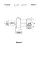
- FIG. 1is a block diagram illustration of a preferred arrangement of an apparatus embodying the present invention to provide a telephone/facsimile machine/data modem shared-line system;
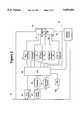
- FIG. 2is a block diagram of a preferred embodiment of a system utilizing the method of the present invention.
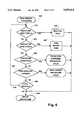
- FIGS. 3-9are flowcharts illustrating the preferred method of the present invention.
- FIG. 1shows a typical shared-line telephone/facsimile system utilizing the method of the present invention.
- a standard telephone line 1 from a telephone line networkenters the wall of a dwelling and terminates at a standard telephone line wall jack 2.
- wall jack 2will generally have multiple female socket connections 4 of the "USOC" variety which are connected to the single telephone line 1.
- a telephone 12is connected to one of the sockets 4.
- a line sharing device in accordance with the present invention, represented by numeral 10 in FIG. 1preferably provides connectivity for a facsimile machine 20, data modem 22, and conventional telephone answering device 24, to the telephone line 11.
- a personmay answer a call via telephone 12. If the call is not answered, the device 10 will either ring the facsimile machine 20, ring the data modem 22, or allow a user to set certain variables, which will be described later.
- FIG. 2is a preferred embodiment of a device employing the present invention.
- a standard telephone line 32is internally connected, in parallel, to four main components including a ring detector 40, an audio coupler 42, an off-hook detector 82, and a selector switch 80.
- the ring detector 40can be a conventional detection circuit for detecting standard telephone "ring" signals on a line. This circuit is generally available in I.C. chip form, in particular, a standard 4N32 integrated circuit isolator device can be used.
- the ring detector 44detects high voltage A.C. across the incoming telephone line 30, indicating an incoming call, and it outputs a signal indicating the detection of rings to a CPU 60.
- the ring detectormay also be of the type that can distinguish "distinctive" rings in a conventional way, outputting a predetermined different signal associated with each different ring to CPU 60.
- the audio coupler 42can be a standard off-the-shelf audio coupler (also as an I.C. chip) and is used to couple the signals of the incoming line to both a commonly known "handshake" detector circuit 54 and a standard decoder circuit 52.
- the handshake detector circuit 54in this preferred embodiment includes a tone decoder. Other equivalent decoders and decoder circuits could be implemented in a manner well known in the art.
- the tone decoderis set to detect a frequency of 1100 Hz. The bulk of today's fax machines send their CNG handshake signals at this frequency.
- the outputs of both the decoder circuit 52 and the handshake detector circuit 54are used as inputs to CPU 60.
- the handshake detector circuit 54detects any handshake signals on telephone line 30 after the call is answered either by a person, an answering machine, or off-hook simulator 74 (described later).
- the handshake detector circuit 54outputs a predetermined signal to CPU 60 via line 55 when a handshake signal is detected.
- CPU 60Upon notification by circuit 54 of a handshake signal, CPU 60 "rings" (described later) the facsimile machine on line 81 and, when the facsimile machine answers, connects it to telephone line 30 through selector switch 80.
- the known off-hook detector circuit 82detects off-hook conditions existing on both the input telephone line 30 and at the facsimile machine (via line 81). When an off-hook condition is detected at the telephone line 30 or line 81, the off-hook detector circuit 82 sends a predetermined signal via line 61 to the CPU 60.
- Ring simulator 70can include a suitable conventional oscillator circuit.
- the oscillator circuitprovides a two second "ring" signal at a predetermined frequency, which is 20 Hz in this preferred embodiment.
- the frequency of 20 Hzis chosen because all fax machines, new or old, respond to input "ring" signals at 20 Hz, whereas only certain older fax machines recognize a 60 Hz "ring" signal.
- Ring simulator 70preferably includes a step up transformer.
- the output of the oscillatorsimulates a standard telephone "ring” signal, similar in frequency and on/off “ring” cycle except that the peak-to-peak voltage is low and needs, to be stepped-up before it is sent to an isolated facsimile machine or data modem.
- the output of the oscillatoris sent first to a step-up transformer.
- the transformermust be specifically designed to receive and step-up input signals of 20 Hz to the proper voltage of telephone "ring” signals.
- the output of the ring simulator 70is connected to the selector switch 80, described later, and is used by the CPU 60 to "ring” either the facsimile machine or the data modem.
- the facsimile machine or the data modemreads the incoming simulated "ring” signals and answers the incoming call as if it were first being received from the telephone network.
- the exchange simulator 72is used by the CPU 60 to selectively isolate the connected facsimile machine and data modem from the telephone line 30 and while isolated, to provide the facsimile machine and the data modem with a simulated input so that an incoming call may be answered by another device such as a telephone receiver or an answering machine, without signalling or otherwise activating the facsimile machine or data modem.
- the exchange simulator 72therefore allows the facsimile machine at line 81 and data modem at line 83 to sense that there is no incoming call, facsimile, voice or data.
- a conventional off-hook simulator 74is used by CPU 60 to "answer" an incoming call. If a person or answering machine has not answered an incoming call during the delay period, the CPU 60 "answers” the call via simulator 74.
- the audio coupler 42senses the signal transmitted so that DTMF tones may be detected by decoder 52, or handshake signals may be detected by handshake detector 54.
- the CPU 60also controls an "on hold” device 78.
- the "on hold” device 78is used by CPU 60 to put a call on hold in a known manner, that is, holding the line in an answered state. Additionally, CPU 60 also turns on or off the LED 104 to signal a user.
- the CPU 60controls a known type of selector switch 80.
- the selector switch 80connects one or more inputs (reference numbers 71, 73, 75, and 77) to one or more outputs (81, 83, 85) in response to a control signal transmitted by CPU 60 via control line 91.
- CPU 60first determines via off-hook detector 82 if the facsimile machine 20 or modem device is off-hook (step 320). If not, the CPU 60 determines if the telephone 12 is off-hook (step 340). If the telephone 12 is not off-hook, the CPU 60 determines if a ring signal is being received from ring detector 40 (step 340). If a ring signal is not being received, the steps 320-340 are repeated.
- the CPU 60would perform a facsimile off-hook procedure. Referring now to the off-hook procedure illustrated in FIG. 4, if the CPU 60 determines that the facsimile machine 20 or modem 22 was off-hook for at least 0.5 seconds, the CPU 60 blinks the LED 104 once per second until the facsimile machine 20 or modem 22 is no longer off-hook (steps 410-440).
- CPU 60performs a telephone off-hook procedure. If the telephone 12 was off-hook for at least 0.5 seconds, the CPU 60 determines via decoder 50 if a DTMF digit was received (step 520). If a DTMF digit was not received, control returns to step 520 repetitively until there is no longer an off-hook signal, at which time the telephone off-hook procedure ends (step 540). If a DTMF digit was received, the CPU 60 performs a programming procedure (FIG. 9), to be described later, and then "hangs up" the telephone via on-hook simulator 76 (step 560).
- a programming procedureFOG. 9
- ring detector circuit 40detects a "ringing" signal on line 30 during step 340, ring detector 40 signals CPU 60 accordingly, and CPU 60 performs a "ring service procedure" (FIG. 6).
- ring detector 40detects a predetermined distinctive "ring” signal on line 30 (step 610), in this case a ring type designated as ring type 1, CPU 60 routes the "ring” signal to the facsimile machine 20 through selector switch 80 (step 680). The facsimile machine 20 then answers the call in the usual manner.
- the ring detector 40instead, detects a second predetermined distinctive "ring” on line 30 (step 620), the "ring" signal is instead be routed to data modem 22 through selector switch 80 (step 690), and the call is be "transferred” in the same manner as described above in connection with the facsimile machine.
- the CPU 60determines if the phone was answered via off hook detector 82 (630). If an off-hook condition is detected, CPU 60 performs a "phone was answered" procedure, described later in connection with FIG. 8.
- CPU 60determines whether a ring counter expired (step 640).
- the ring counterexpires after CPU 60 has detected a predetermined number of rings on line 30 via ring detector 40. If the ring counter has expired, CPU 60 performs a "ring expired" procedure, described later.
- steps 610-650 of the ring service procedureare repeated.
- the "ring service" procedure of FIG. 6provides the initial routing of the signal from line 30 before the call is answered.
- CPU 60If a DTMF digit is detected via audio coupler 42 and decoder 52 (step 740), CPU 60 initiates the "programming procedure" (FIG. 9, described later). If instead, handshake detector 54 detects CNG tones (step 750) or a local "3" from telephone handset 12 is detected (step 760), CPU 60 rings the facsimile machine 20 via ring simulator 70 through selector switch 80, allowing the facsimile machine 20 to "answer" the call in the usual manner.
- step 770If the time has not expired (step 770) as set in step 730, steps 740-770 are repeated. If the timer expired (step 770), CPU 60 rings the data modem 22 via ring simulator 70 through selector switch 80 and allows the data modem to "answer" the call in the usual manner.
- CPU 60starts a 20 second timer (step 802) and then determines whether a DTMF digit was received (step 803) via audio coupler 42 and decoder 52. If a DTMF digit was detected, CPU 60 stops the timer (step 817) and initiates the programming procedure (FIG. 9 described later).
- facsimile CNG toneswere instead detected via handshake detector 54 (step 804) or a local digit "3" was detected, the line is placed on hold (step 816) with "on hold” device 78 and CPU 60 causes ringing of the facsimile machine 20 (step 809) via ring simulator 70 and selector switch 80, and the facsimile machine is permitted to answer the call in the usual manner.
- steps 803-806are repeated (step 806). If the timer expired (step 806) and the telephone answering machine answered the call (step 810) CPU 60 rings the data modem 22 via ring simulator 70 and selector switch 80, connecting line 83 to the call on line 30 and disconnecting the telephone answering device on line 85. If the telephone answering device 24 did not answer the call (step 810), CPU 60 performs steps 812-814 in the same fashion it performed steps 803-805.
- step 803 of the procedure of FIG. 8the CPU 60 senses the DTMF digit and stops the timer (step 817). CPU 60 then proceeds to the programming procedure (step 808) to insure that the caller was not intending to access the programming feature. Assuming the caller did not wish to access the programming feature, the procedure 800 ends with the TAD simply retaining control of the phone line that it initially answered, allowing a caller to leave a message. The TAD then hangs up in a conventional manner.
- the "phone was answered" proceduretakes care of the transfer of all calls, if necessary, if the call was answered either by a telephone answering device 24 or a telephone handset.
- CPU 60determines whether a valid security code has been received (step 903).
- the valid security codeis comprised of DTMF digits previously stored in the memory (not shown) of CPU 60. If a valid code is entered, CPU 60 outputs a "beep" signal in a known manner along phone line 30 (step 904). Next, CPU 60 checks for a valid program code (step 905). Program codes are sets of DTMF digits having special meaning to CPU 60.
- Each codeis equated to a particular function that CPU controls such as changing certain internal variables such as the number of rings CPU 60 should wait before it "answers” the phone via the "ring expired” procedure 710. If CPU 60 receives a valid program code (step 905) it performs the predetermined function (step 906), outputs "beep” signals (step 907), and then "hangs up” the telephone line.
- step 908If the second digit received was a DTMF "#" digit (step 908) and the third digit was a DTMF "1,” CPU 60 rings the facsimile machine 20, allowing it to answer the call in the usual manner. If the third digit were a "2", the data modem 22 is instead rung.
Landscapes
- Engineering & Computer Science (AREA)
- Signal Processing (AREA)
- Multimedia (AREA)
- Computer Networks & Wireless Communication (AREA)
- Facsimile Transmission Control (AREA)
- Telephonic Communication Services (AREA)
Abstract
Description
Claims (4)
Priority Applications (1)
| Application Number | Priority Date | Filing Date | Title |
|---|---|---|---|
| US08/667,918US5699414A (en) | 1994-10-03 | 1996-06-20 | Method and apparatus for sharing a single telephone line between a facsimile machine, data modem, telephone answering device, and a person |
Applications Claiming Priority (2)
| Application Number | Priority Date | Filing Date | Title |
|---|---|---|---|
| US08/317,932US5666403A (en) | 1994-10-03 | 1994-10-03 | Method and apparatus for sharing a single telephone line between a facsimile machine, data modem, telephone answering device, and a person |
| US08/667,918US5699414A (en) | 1994-10-03 | 1996-06-20 | Method and apparatus for sharing a single telephone line between a facsimile machine, data modem, telephone answering device, and a person |
Related Parent Applications (1)
| Application Number | Title | Priority Date | Filing Date |
|---|---|---|---|
| US08/317,932ContinuationUS5666403A (en) | 1994-10-03 | 1994-10-03 | Method and apparatus for sharing a single telephone line between a facsimile machine, data modem, telephone answering device, and a person |
Publications (1)
| Publication Number | Publication Date |
|---|---|
| US5699414Atrue US5699414A (en) | 1997-12-16 |
Family
ID=23235887
Family Applications (2)
| Application Number | Title | Priority Date | Filing Date |
|---|---|---|---|
| US08/317,932Expired - Fee RelatedUS5666403A (en) | 1994-10-03 | 1994-10-03 | Method and apparatus for sharing a single telephone line between a facsimile machine, data modem, telephone answering device, and a person |
| US08/667,918Expired - Fee RelatedUS5699414A (en) | 1994-10-03 | 1996-06-20 | Method and apparatus for sharing a single telephone line between a facsimile machine, data modem, telephone answering device, and a person |
Family Applications Before (1)
| Application Number | Title | Priority Date | Filing Date |
|---|---|---|---|
| US08/317,932Expired - Fee RelatedUS5666403A (en) | 1994-10-03 | 1994-10-03 | Method and apparatus for sharing a single telephone line between a facsimile machine, data modem, telephone answering device, and a person |
Country Status (1)
| Country | Link |
|---|---|
| US (2) | US5666403A (en) |
Cited By (9)
| Publication number | Priority date | Publication date | Assignee | Title |
|---|---|---|---|---|
| US5938745A (en)* | 1997-06-25 | 1999-08-17 | Intel Corporation | Arbitrator for modem in a system without shared process space that passes a duplicate handle to a first listening application with matching identification string |
| US5949860A (en)* | 1997-02-10 | 1999-09-07 | Samsung Electronics Co., Ltd. | Method and apparatus for receiving facsimile message in facsimile connected to external telephone |
| US6480603B1 (en) | 1998-11-06 | 2002-11-12 | Nortel Networks Limited | Device which reduces central office battery current during modem connections |
| US6559979B1 (en)* | 1996-12-26 | 2003-05-06 | Minolta Co., Ltd. | Recording apparatus and information processing system including the same |
| US6671357B1 (en) | 1999-12-01 | 2003-12-30 | Bellsouth Intellectual Property Corporation | Apparatus and method for interrupting data transmissions |
| US6744873B1 (en)* | 2000-01-15 | 2004-06-01 | William E. McCracken | Telephone accessory device |
| US20080273688A1 (en)* | 2007-05-05 | 2008-11-06 | Wei Lu | Phone computing machine (PCM) |
| US20090161847A1 (en)* | 2007-12-21 | 2009-06-25 | David Kormann | System and Method for Remotely Diagnosing and Reporting Failures in Network Equipment |
| US8285292B1 (en)* | 2000-02-11 | 2012-10-09 | At&T Mobility Ii Llc | Detection of cross-connection between a wireless loop network and another loop network at a subscriber's premises |
Families Citing this family (15)
| Publication number | Priority date | Publication date | Assignee | Title |
|---|---|---|---|---|
| DE19604875C2 (en)* | 1996-02-10 | 2002-10-31 | Deutsche Telekom Ag | Method and device for telephone-fax switching |
| US5726979A (en)* | 1996-02-22 | 1998-03-10 | Mci Corporation | Network management system |
| JP3207746B2 (en)* | 1996-03-25 | 2001-09-10 | シャープ株式会社 | Facsimile machine |
| US5815285A (en)* | 1996-08-22 | 1998-09-29 | Hewlett-Packard Company | Facsimile device with user-friendly automatic receive mode |
| US6108405A (en)* | 1998-09-24 | 2000-08-22 | Ericsson Inc. | Handling incoming data/facsimile transmissions and voice calls in a computer/telephony integrated system |
| AUPP747598A0 (en)* | 1998-12-03 | 1998-12-24 | Reznik, Michael | The share call card-the integration of virtual telephone line with telephone for public telephone network users |
| AU770934B2 (en)* | 1998-12-03 | 2004-03-11 | Sharecall Technologies Pty Ltd | Telephone line sharing module |
| US6880012B1 (en) | 2000-08-02 | 2005-04-12 | International Business Machines Corporation | System, method, and program for establishing modem communication between a master computer system and a plurality of slave computer systems through a common serial communication channel |
| US20030194074A1 (en) | 2000-12-21 | 2003-10-16 | Jayson Newlin | Methods and systems for communicating and controlling facsimile information |
| US8416925B2 (en) | 2005-06-29 | 2013-04-09 | Ultratec, Inc. | Device independent text captioned telephone service |
| US7230745B1 (en)* | 2002-04-08 | 2007-06-12 | Captaris, Inc. | Document transmission and routing with recipient control, such as facsimile document transmission and routing |
| US8515024B2 (en) | 2010-01-13 | 2013-08-20 | Ultratec, Inc. | Captioned telephone service |
| US11258900B2 (en) | 2005-06-29 | 2022-02-22 | Ultratec, Inc. | Device independent text captioned telephone service |
| US20080285088A1 (en)* | 2007-05-16 | 2008-11-20 | Microsoft Corporation | Techniques to manage facsimile communications |
| JP4906701B2 (en)* | 2007-12-14 | 2012-03-28 | キヤノン株式会社 | Line control apparatus, line control method, program, storage medium |
Citations (13)
| Publication number | Priority date | Publication date | Assignee | Title |
|---|---|---|---|---|
| US4660218A (en)* | 1984-03-14 | 1987-04-21 | Hashimoto Corporation | Apparatus for switching telephone line a response device, a data terminal or a telephone |
| US4663778A (en)* | 1984-01-31 | 1987-05-05 | Canon Kabushiki Kaisha | Communication apparatus |
| US4788714A (en)* | 1984-10-26 | 1988-11-29 | Hashimoto Corporation | Remote controlling telephone unit for selectively activating one of a plurality of devices |
| US4800439A (en)* | 1986-02-26 | 1989-01-24 | Canon Kabushiki Kaisha | Data communication apparatus adapted to perform data communication and speech communication |
| US4850008A (en)* | 1988-02-29 | 1989-07-18 | Extel Corporation | Method and apparatus for discrimination between different kinds of data transmission |
| US4910764A (en)* | 1989-04-13 | 1990-03-20 | Product Engineering & Manufacturing, Inc. | Facsimile and voice communications interface device |
| US4942600A (en)* | 1988-03-07 | 1990-07-17 | Canon Kabushiki Kaisha | Communication apparatus for generating a call signal from a telephone set to a data terminal |
| US5062133A (en)* | 1989-07-07 | 1991-10-29 | Logotronix Incorporated | Multi-function telephone call management system |
| JPH04238452A (en)* | 1991-01-23 | 1992-08-26 | Matsushita Graphic Commun Syst Inc | Composite type picture communication equipment |
| US5146489A (en)* | 1990-02-20 | 1992-09-08 | It Systems Corporation | Dedicated line eliminator for facsimile/telephone systems |
| US5151972A (en)* | 1989-03-28 | 1992-09-29 | Lynx Automation, Inc. | Apparatus for automatically connecting terminal device to telephone lines |
| JPH0662148A (en)* | 1992-08-07 | 1994-03-04 | Ricoh Co Ltd | Composite terminal equipment |
| US5392334A (en)* | 1993-08-25 | 1995-02-21 | Intel Corporation | Off-hook detection and soft line seizure for telephone line sharing in a computer system |
- 1994
- 1994-10-03USUS08/317,932patent/US5666403A/ennot_activeExpired - Fee Related
- 1996
- 1996-06-20USUS08/667,918patent/US5699414A/ennot_activeExpired - Fee Related
Patent Citations (13)
| Publication number | Priority date | Publication date | Assignee | Title |
|---|---|---|---|---|
| US4663778A (en)* | 1984-01-31 | 1987-05-05 | Canon Kabushiki Kaisha | Communication apparatus |
| US4660218A (en)* | 1984-03-14 | 1987-04-21 | Hashimoto Corporation | Apparatus for switching telephone line a response device, a data terminal or a telephone |
| US4788714A (en)* | 1984-10-26 | 1988-11-29 | Hashimoto Corporation | Remote controlling telephone unit for selectively activating one of a plurality of devices |
| US4800439A (en)* | 1986-02-26 | 1989-01-24 | Canon Kabushiki Kaisha | Data communication apparatus adapted to perform data communication and speech communication |
| US4850008A (en)* | 1988-02-29 | 1989-07-18 | Extel Corporation | Method and apparatus for discrimination between different kinds of data transmission |
| US4942600A (en)* | 1988-03-07 | 1990-07-17 | Canon Kabushiki Kaisha | Communication apparatus for generating a call signal from a telephone set to a data terminal |
| US5151972A (en)* | 1989-03-28 | 1992-09-29 | Lynx Automation, Inc. | Apparatus for automatically connecting terminal device to telephone lines |
| US4910764A (en)* | 1989-04-13 | 1990-03-20 | Product Engineering & Manufacturing, Inc. | Facsimile and voice communications interface device |
| US5062133A (en)* | 1989-07-07 | 1991-10-29 | Logotronix Incorporated | Multi-function telephone call management system |
| US5146489A (en)* | 1990-02-20 | 1992-09-08 | It Systems Corporation | Dedicated line eliminator for facsimile/telephone systems |
| JPH04238452A (en)* | 1991-01-23 | 1992-08-26 | Matsushita Graphic Commun Syst Inc | Composite type picture communication equipment |
| JPH0662148A (en)* | 1992-08-07 | 1994-03-04 | Ricoh Co Ltd | Composite terminal equipment |
| US5392334A (en)* | 1993-08-25 | 1995-02-21 | Intel Corporation | Off-hook detection and soft line seizure for telephone line sharing in a computer system |
Non-Patent Citations (2)
| Title |
|---|
| Autoswitcher Description, Hello Direct Catalog, Winter 1991, p. 31.* |
| Pathfinder Description, Viking Electronics, Inc. Catalog, 1992, p. 10.* |
Cited By (11)
| Publication number | Priority date | Publication date | Assignee | Title |
|---|---|---|---|---|
| US6559979B1 (en)* | 1996-12-26 | 2003-05-06 | Minolta Co., Ltd. | Recording apparatus and information processing system including the same |
| US5949860A (en)* | 1997-02-10 | 1999-09-07 | Samsung Electronics Co., Ltd. | Method and apparatus for receiving facsimile message in facsimile connected to external telephone |
| US5938745A (en)* | 1997-06-25 | 1999-08-17 | Intel Corporation | Arbitrator for modem in a system without shared process space that passes a duplicate handle to a first listening application with matching identification string |
| US6279054B1 (en) | 1997-06-25 | 2001-08-21 | Intel Corporation | Arbitrator for multiple processes sharing a port |
| US6480603B1 (en) | 1998-11-06 | 2002-11-12 | Nortel Networks Limited | Device which reduces central office battery current during modem connections |
| US6671357B1 (en) | 1999-12-01 | 2003-12-30 | Bellsouth Intellectual Property Corporation | Apparatus and method for interrupting data transmissions |
| US6744873B1 (en)* | 2000-01-15 | 2004-06-01 | William E. McCracken | Telephone accessory device |
| US8285292B1 (en)* | 2000-02-11 | 2012-10-09 | At&T Mobility Ii Llc | Detection of cross-connection between a wireless loop network and another loop network at a subscriber's premises |
| US20080273688A1 (en)* | 2007-05-05 | 2008-11-06 | Wei Lu | Phone computing machine (PCM) |
| US20090161847A1 (en)* | 2007-12-21 | 2009-06-25 | David Kormann | System and Method for Remotely Diagnosing and Reporting Failures in Network Equipment |
| US8923486B2 (en)* | 2007-12-21 | 2014-12-30 | At & T Intellectual Property I, Lp | System and method for remotely diagnosing and reporting failures in network equipment |
Also Published As
| Publication number | Publication date |
|---|---|
| US5666403A (en) | 1997-09-09 |
Similar Documents
| Publication | Publication Date | Title |
|---|---|---|
| US5699414A (en) | Method and apparatus for sharing a single telephone line between a facsimile machine, data modem, telephone answering device, and a person | |
| US5146489A (en) | Dedicated line eliminator for facsimile/telephone systems | |
| US5502761A (en) | Apparatus and method for relaying calling information to a pager or alternate telephone | |
| US5444771A (en) | Facsimile machine having answering function | |
| US5440619A (en) | Voice, data and facsimile modem with modified ringback answering | |
| JPH0423460B2 (en) | ||
| US5267302A (en) | Facsimile system | |
| US5594788A (en) | Telephone system and interface device | |
| US6091721A (en) | Apparatus for telephone communication over plural channels | |
| KR0134535Y1 (en) | Automatic connection device by computer phone call | |
| KR20000016349A (en) | Connecting telephones, fax machines and computers in intelligent network | |
| US20020154754A1 (en) | Call screener | |
| JP2922350B2 (en) | Telephone device and connection control method thereof | |
| JP2633253B2 (en) | Telephone terminal device | |
| JPS58187050A (en) | Automatic dial device | |
| JP2947433B2 (en) | Key telephone equipment | |
| JP2982686B2 (en) | Private branch exchange | |
| JPH07107197A (en) | No ringing communication device | |
| JPS6328388B2 (en) | ||
| JP2001086252A (en) | Intercom device with transfer function | |
| KR960012903A (en) | International communication CALLING control device and its control method | |
| JPS61274576A (en) | Facsimile equipment | |
| JPH10164185A (en) | Incoming call automatic transfer method utilizing caller number in terminal equipment | |
| JP2001069539A (en) | Direct-in dial control method and key telephone system having direct-in dial control function | |
| JPH01192249A (en) | Communications system |
Legal Events
| Date | Code | Title | Description |
|---|---|---|---|
| AS | Assignment | Owner name:SUNTRUST BANK, ATLANTA, AS AGENT, GEORGIA Free format text:SECURITY AGREEMENT;ASSIGNORS:TELEDEX LLC;TT SYSTEMS LLC;REEL/FRAME:010310/0734 Effective date:19991001 | |
| AS | Assignment | Owner name:TT SYSTEMS LLC, NEW YORK Free format text:ASSIGNMENT OF ASSIGNORS INTEREST;ASSIGNOR:TT SYSTEMS CORP.;REEL/FRAME:010321/0186 Effective date:19991001 | |
| FPAY | Fee payment | Year of fee payment:4 | |
| AS | Assignment | Owner name:DAVAL TECHNOLOGIES, INC., NEW YORK Free format text:ASSIGNMENT OF ASSIGNORS INTEREST;ASSIGNOR:TT SYSTEMS LLC;REEL/FRAME:013943/0700 Effective date:20030404 Owner name:TT SYSTEMS LLC, NEW YORK Free format text:ASSIGNMENT OF ASSIGNORS INTEREST;ASSIGNOR:TT SYSTEMS CORPORATION;REEL/FRAME:013943/0695 Effective date:20030403 | |
| REMI | Maintenance fee reminder mailed | ||
| LAPS | Lapse for failure to pay maintenance fees | ||
| STCH | Information on status: patent discontinuation | Free format text:PATENT EXPIRED DUE TO NONPAYMENT OF MAINTENANCE FEES UNDER 37 CFR 1.362 | |
| FP | Lapsed due to failure to pay maintenance fee | Effective date:20051216 | |
| AS | Assignment | Owner name:TMX FUNDING, INC., COLORADO Free format text:CONVEYANCE BY FORECLOSURE;ASSIGNORS:TELECOM INDUSTRIES LLC;TELEDEX LLC;TT SYSTEMS LLC;REEL/FRAME:026188/0602 Effective date:20091218 |