US5699226A - Computer docking station having interchangeable receivers configured for docking various sized portable computers - Google Patents
Computer docking station having interchangeable receivers configured for docking various sized portable computersDownload PDFInfo
- Publication number
- US5699226A US5699226AUS08/600,888US60088896AUS5699226AUS 5699226 AUS5699226 AUS 5699226AUS 60088896 AUS60088896 AUS 60088896AUS 5699226 AUS5699226 AUS 5699226A
- Authority
- US
- United States
- Prior art keywords
- base
- receiver
- portable computer
- connector
- docking apparatus
- Prior art date
- Legal status (The legal status is an assumption and is not a legal conclusion. Google has not performed a legal analysis and makes no representation as to the accuracy of the status listed.)
- Expired - Lifetime
Links
Images


Classifications
- G—PHYSICS
- G06—COMPUTING OR CALCULATING; COUNTING
- G06F—ELECTRIC DIGITAL DATA PROCESSING
- G06F1/00—Details not covered by groups G06F3/00 - G06F13/00 and G06F21/00
- G06F1/16—Constructional details or arrangements
- G06F1/1613—Constructional details or arrangements for portable computers
- G06F1/1632—External expansion units, e.g. docking stations
Definitions
- the present inventionrelates generally to computer docking stations and more particularly to a docking apparatus for docking various sized portable computers that have different exterior dimensions and a common portable computer connector.
- a port replicatoris a relatively small device which can be positioned on a desktop or other horizontal work surface and serves as an interface between a portable computer and the desktop peripherals with which it is to be used.
- the port replicatorincludes a housing adapted to rest on a horizontal surface and having a rear side from which a series of connecting cables extend to the selected peripheral equipment.
- the front side of the port replicatoris engagable with the portable computer in a manner so that a connector on the portable computer is engaged with a mating connector on the port replicator to enable the portable computer to utilize the desired peripheral equipment.
- One such docking apparatuscomprises a base having positioned on one end an electronics enclosure which includes the electronics necessary to interconnect the portable computer with the desired peripheral equipment.
- the electronics enclosuremay also include a cable cover to cosmetically cover the cable connections.
- a receiveris positioned to matingly engage the bottom and sides of a portable computer so that it may slide into mating engagement with the docking apparatus.
- Mating engagementis achieved by moving a connector positioned on a rear end of the portable computer into engagement with a connector positioned on the docking apparatus so that the portable computer is matingly engaged with the docking apparatus in operable electrical contact for use with the desired peripheral equipment.
- the portable computer display screencan be raised and the portable computer can be used while docked in contact with the peripheral equipment.
- the docking apparatusmay include fittings for engagement with a monitor stand so that the docking apparatus with the docked portable computer can be stored under the monitor stand when the portable computer display screen is dosed.
- peripheral equipment in a particular officemay be used by a number of users.
- Various users of the peripheral equipmentmay have portable computers which are of different models, different capabilities and the like, but of a common family of portable computers.
- Such a family of portable computerscan be designed to have a portable computer connector which is common to all members of the family of portable computers.
- the portable computersmay not all be readily mated with a single docking apparatus because the receiver is not configured to position the portable computer properly for mating engagement of the portable computer connector with the docking apparatus connector.
- a different docking apparatusis required for each portable computer having a different configuration.
- a different docking apparatusis typically required when a user upgrades to a portable computer having increased functionality due to differences in size of the computer and in the positioning of the portable computer connector.
- the present inventionaccordingly, provides an apparatus for docking various sized portable computers at the same docking station that overcomes or reduces disadvantages and limitations associated with prior systems.
- the inventionprovides an apparatus for docking selected portable computers of a family of portable computers, each of the portable computers having a front end and a rear end, a first side and a second side, a top and a bottom, and a portable computer connector positioned on the rear end of the portable computer.
- the docking apparatuscomprises a base having a first end and a second end and an electronics enclosure positioned on the base between the first end and the second end, the electronics enclosure having a first end positioned to extend generally perpendicularly from a first side to a second side of the base and generally perpendicularly upwardly from the base to form a wall.
- a docking apparatus connectoris positioned on the wall and configured to matingly engage the portable computer connector.
- a receiveris positioned on the base and configured to matingly engage the bottom and a first and a second side of at least one portable computer to position at least one portable computer for mating engagement of the portable computer connector and the docking apparatus connector.
- the receivermay be configured as a part of the base of the docking apparatus. Alternatively, the receiver may be formed to be removably positioned on the base of the docking apparatus. Further, the receiver may be formed by removably positioning a plurality of attachments which are configured to matingly engage one or more portable computers on the base. The receiver may also comprise a plurality of extendable members which are extendable to engage and support a portable computer in a desired position.
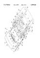
- FIG. 1is an exploded, perspective view of a docking apparatus of the present invention.
- FIG. 2is an end view from section line 2--2 of FIG. 1 of a receiver positioned on the base of the docking apparatus showing the positioning of a portable computer supported therein.
- FIG. 3is an end view of an alternative receiver taken from the position of section line 2--2 of FIG. 1 that is formed as a part of the base showing a portable computer supported therein.
- FIG. 4is an end view of the receiver of FIG. 3 taken from the position of section line 2--2 of FIG. 1 showing a different portable computer supported therein.
- FIG. 5is an end view taken from the position of section line 2--2 of FIG. 1 of another alternative receiver that is form by positioning attachments on the base and shows a portable computer supported by the attachments.
- FIG. 6is a perspective view of a receiver having extendable members positioned in its floor for supporting a portable computer.
- FIG. 7is a cross sectional end view from section line 7--7 of FIG. 6 showing the extendable members in an extended position to support a portable computer.
- FIG. 8is a cross sectional end view from section line 7--7 of FIG. 6 showing the extendable members in a retracted position to support a different sized portable computer.
- FIG. 9is a cross sectional end view from section line 7--7 of FIG. 6 of an alternative embodiment of the apparatus of FIG. 6 wherein extendable members are also positioned in the sides of the receiver.
- FIG. 10is a perspective view of an alternative embodiment of the docking apparatus of the present invention.
- FIG. 11is an enlarged, cross-sectional view from section line 11--11 of FIG. 10 showing a detail of the engagement mechanism between the base and receiver.
- FIG. 12is an enlarged, cross-sectional view from section line 12--12 of FIG. 10 showing a detail of the mating engagement of the components of the invention.
- the reference numeral 10refers to a docking apparatus of the present invention resting on a surface 12.
- the docking apparatus 10comprises a base 14 having a side 16, a side 18, a front end 20 and a rear end 22.
- the base 14may be formed, as shown, as a framework or as a solid member. Fittings 24 are optionally provided on the base 14 for mounting a monitor stand (not shown) above the docking apparatus 10.
- An electronics enclosure 26is provided which includes the electrical components necessary to achieve electrical connection of a portable computer with peripheral equipment or the like and other functionalities not available in the portable computer enclosure.
- the electronics enclosure 26includes a front end 28 and a rear end 30, and is connected by cables (not shown) to peripheral equipment and the like.
- the electronics enclosure 26also includes a side 32 and a side 34.
- End 28is formed as a wall which supports a connector 36 which includes guide pins 38 and connector pins 40.
- Ejectors 42are positioned on end 28 to eject portable computers from engagement with connector 36 when desired.
- Ejectors 42may be mechanical or electromechanical and are operated by a switch or lever 44, shown on the side 32 of the electronics enclosure 26.
- the receiver 46includes rafts 58 which may be positioned on a floor 60 of the receiver 46 and optionally on inner walls 62 of sidewalls 64 of the receiver 46 to facilitate sliding a portable computer into the receiver 46.
- the receiver 46 as shownis maintained in position on the base 14 by a manual lock 66 positioned on the receiver 46, and adapted for engagement with a receptacle 68 positioned on the base 14 to maintain the receiver 46 in place.
- Slots 70are provided on the base 14, to receive tabs (not shown) on the receiver 46 to further secure the receiver 46 in position on the base 14.
- a portable computer 72is positioned in the receiver 46 positioned on the base 14.
- the portable computer 72has a portable computer connector 74 positioned on its rear end and is positioned between the sidewalls 64 for mating engagement of the connector 74 with the connector 36.
- the connector 74contains receptacles 76 for the guide pins 38 and receptacles 78 for the connector pins 40. The pins and receptacles could be reversed between the connector 36 and the connector 74.
- FIGS. 3 and 4disclose an alternate embodiment of the present invention wherein the receiver 46 is formed as a part of the base 14.
- the same receiver 46is adapted to support two portable computers 72a and 72b.
- the sidewalls 64are adapted to matingly engage the sides and bottom of the portable computers 72a and 72b for mating engagement of the connector 74 with the connector 36.
- Each of the sidewalls 64includes a bearing surface 64a which supports the bottom of the portable computer 72a.
- the portable computer 72b having a different exterior configurationcan be supported in receiver 46, as shown in FIG. 4.
- the receiver 46is formed by positioning removable attachments 80 on the sides of the base 14 to form the sidewalls 64 as shown.
- the attachments 80may be removably attached to base 14 by any convenient method, such as screws, friction fittings, mating tabs and slots, and the like, as known to those skilled in the art.
- Various attachments 80 having different dimensionscan be provided to receive a variety of portable computers 72.
- FIG. 6an alternate embodiment of the docking apparatus of the present invention is shown.
- the receiver 46is shown as a hollow member having slots 82 positioned in the floor 60 of the receiver 46.
- the slots 82are positioned for extension of inner extendable members 84 and outer extendable members 86 (shown in FIG. 7) upwardly through the floor 60 of the receiver 46.
- the receiver 46 with members 84 and 86 retractedis adapted to receiver a portable computer of a size compatible with the sidewalls 64 and the floor 60 of the receiver 46 as configured.
- extendable members 84 and 86have been extended to support the portable computer 72 in the receiver 46.
- the extendable members 84 and 86may be extended by any suitable mechanical or electromechanical means and are activated by a switch 88, shown on the side 16 of the receiver 46.
- a portable computer 72is shown positioned in the receiver 46 with the extendable members 84 and 86 in a retracted position to accommodate a larger portable computer 72.
- FIG. 9an alternate embodiment of the receiver 46 of FIG. 6 is shown.
- horizontally extendable members 90are positioned in the sidewalls 64.
- the extendable members 84, 86 and 90may be extended for variable distances to accommodate various portable computers 72 in place.
- the extendable members 84, 86 and 90are rails which are adapted to slidably engage the sidewalls and bottom of the portable computer 72 to position it for mating engagement of the connector 74 with the connector 36.
- the extendable members 84, 86 and 90may be moved into a desired position by electromechanical devices 92 which may be controlled manually by the switch 88 or by a computer program designed to position the extendable rails 84, 86 and 90 in desired positions to accommodate different external portable computer configurations.
- the docking apparatus 100referes to a docking apparatus of an alternative embodiment of the present invention.
- the docking apparatus 100comprises a base 102 having a sidewall 104, a sidewall 106, a front end 108 and a rear end 110.
- the base 102may be formed as a framework or as a solid member, as shown.
- Fittings 112are optionally provided on the base 102 for mounting a monitor stand (not shown) above the docking apparatus 100.
- An electronics housing 114is provided which includes the electrical components (not shown) necessary to achieve electrical connection of a portable computer with peripheral equipment or the like.
- the electronics housing 114includes a rear portion 116 and a front portion 118.
- the rear portion 116may be removably attached to the base 102 and to the front portion 118 by any convenient method, such as mating tabs and slots, and the like, as known to those skilled in the art, and contains depressions 120 for facilitating such removal.
- the front portion 118 of the electronics housing 114includes a front end 122, a side 124 and a side 126. End 122 supports a connector 128 which includes guide pins 130 and connector pins 132.
- Ejectors 134extend from within the electronics housing 114 through the end 122 to eject portable computers from engagement with the connector 128 when desired.
- the ejectors 134may be mechanical or electromechanical and are operated by a switch or lever 136, shown on the side 124 of the front portion 118 of the electronics housing 114.
- the receiver 138includes a floor 148, positioned on which are rails 150, each having a sloped leading edge 150a, and a raised surface 152 for receiving a portable computer 154 onto the receiver 138.
- the portable computer 154has corresponding rails 156 and feet 158 extending downwardly therefrom to further facilitate the entry and positioning of the portable computer 154 onto the receiver 138 as shown in FIG. 11.
- the receiver 138 as shown in FIG. 10is maintained in position on the base 102 not only through engagement of the sidewalls 104 and 106 of the base 102, but (referring to both FIG. 10 and FIG. 12) by a locking tab 160 that extends downwardly from a circular partial cutout 162 in the floor 148 of the receiver 138, that is adapted for engagement with a slot 164 positioned near the front end 108 of the base 102 behind a sloped surface 166.
- a plurality of openings 168are provided in the front end 122 of the electronics housing 114 adjacent the base 102 to receive tabs 170 horizontally extending from the rear end 146 of the receiver 138 to further secure the receiver 138 in position on the base 102.
- a plurality of slots 172are provided in the front end 108 of the base 102 to receive tabs 174 horizontally extending from a shoulder 176 formed on the underside of the receiver 138 as shown in FIG. 10 and FIG. 12. When engaged, the shoulder 176 engages the front end 108 of the base 102 to further facilitate the engagement and positioning of the receiver 138 on the base 102.
- the portable computer 154has a portable computer connector 178 positioned on its rear end for mating engagement with the connector 128.
- the connector 178contains receptacles 180 for the guide pins 130 and receptacles (not shown) for the connector pins 132.
- the pins and receptaclescould be reversed between the connector 128 and the connector 178.
- the portable computer 154may also have depressions 182 on its rear end for mating engagement with the ejectors 134.
- the receiver 138is engaged with the base 102 by sliding the receiver 138 onto the base 102 between the sidewalls 104 and 106 of the base.
- the mating of the sidewalls 140 and 142 of the receiver 138 with the sidewalls 104 and 106 of the base 102direct the tabs 170 into the openings 168 and the tabs 174 into the slots 172. Disengagement is prevented by the locking tab 160 that engages the slot 164 after sliding up the surface 166.
- the portable computer 154is then positioned on the receiver 138 by sliding the portable computer 154 onto the sloped edges 150a of the rails 150 between the sidewalls 140 and 142 of the receiver.
- Disengagement of the portable computer 154 from the docking apparatus 100is accomplished by activating the switch 136, which in turn activates the ejectors 134 that urge against the rear end of the portable computer 154 to separate the connectors 128 and 178.
- the receiver 138is disengaged from the base 102 by lifting up on the cutout 162 to lift the locking tab 160 out of the slot 164. The receiver 138 can then be slid off of the base 102 to make room for the next receiver.
- a large number of portable computers from a common family of portable computerscan be docked in the same docking apparatus 100.
- a plurality of receiverscan be provided for mounting on the base to accommodate selected portable computers based upon the external configuration of the portable computers.
- Many manufacturers of portable computersfind it desirable to change the external dimensions of the portable computers because of varied capabilities in the portable computer, fabrication at different facilities, and the like. While such changes may be necessitated by the internal arrangement of electronic components and the like, it is possible to position a common portable computer connector on all such portable computers. Further, while it is desirable to be able to move the location of the portable computer connector to a certain extent, it is also feasible to locate the connector generally in a selected position such as toward the left and generally toward the top of the rear of the portable computer. While the location may not be exactly the same on each portable computer model, the location is in the same general area and suitable for mating with the docking apparatus connector when the portable computer is suitably positioned.
- a large number of selected members of a family of portable computerscan be docked in a common docking apparatus by providing a receiver which is adapted to receive the desired portable computer and which can be positioned on the base of the docking apparatus.
- attachmentscan be used or extendable rafts can be used.
- the rails 150 of the receiver 148could be eliminated or the sidewalls 140 and 142 shortened in length or even eliminated in some cases.
- the sidewalls 140 and 142are not required to properly align the connectors and can thus be eliminated, or simply shortened to still provide course alignment.
- the lever 136could be positioned near the front end of the base 102 to facilitate its access.
Landscapes
- Engineering & Computer Science (AREA)
- Theoretical Computer Science (AREA)
- Computer Hardware Design (AREA)
- Human Computer Interaction (AREA)
- Physics & Mathematics (AREA)
- General Engineering & Computer Science (AREA)
- General Physics & Mathematics (AREA)
- Casings For Electric Apparatus (AREA)
- Details Of Connecting Devices For Male And Female Coupling (AREA)
Abstract
Description
Claims (3)
Priority Applications (1)
| Application Number | Priority Date | Filing Date | Title |
|---|---|---|---|
| US08/600,888US5699226A (en) | 1996-02-13 | 1996-02-13 | Computer docking station having interchangeable receivers configured for docking various sized portable computers |
Applications Claiming Priority (1)
| Application Number | Priority Date | Filing Date | Title |
|---|---|---|---|
| US08/600,888US5699226A (en) | 1996-02-13 | 1996-02-13 | Computer docking station having interchangeable receivers configured for docking various sized portable computers |
Publications (1)
| Publication Number | Publication Date |
|---|---|
| US5699226Atrue US5699226A (en) | 1997-12-16 |
Family
ID=24405460
Family Applications (1)
| Application Number | Title | Priority Date | Filing Date |
|---|---|---|---|
| US08/600,888Expired - LifetimeUS5699226A (en) | 1996-02-13 | 1996-02-13 | Computer docking station having interchangeable receivers configured for docking various sized portable computers |
Country Status (1)
| Country | Link |
|---|---|
| US (1) | US5699226A (en) |
Cited By (59)
| Publication number | Priority date | Publication date | Assignee | Title |
|---|---|---|---|---|
| US5864708A (en)* | 1996-05-20 | 1999-01-26 | Croft; Daniel I. | Docking station for docking a portable computer with a wireless interface |
| US6011687A (en)* | 1998-02-04 | 2000-01-04 | Dell U.S.A., L. P. | Docking station adapter for computer media modules |
| US6023411A (en)* | 1998-01-27 | 2000-02-08 | Dell U.S.A., L.P. | Modular docking tray and method |
| US6028767A (en)* | 1998-05-15 | 2000-02-22 | Compal Electronics Inc. | Externally connected expansion device with replaceable guiding face panel for guiding different portable computers |
| US6040681A (en)* | 1998-10-26 | 2000-03-21 | Hewlett-Packard Company | Enhanced docking tray supports for custom featuring for external battery charging for notebook computers |
| US6061233A (en)* | 1998-01-13 | 2000-05-09 | Samsung Electronics Co., Ltd. | Docking station for a laptop computer |
| US6061234A (en)* | 1999-03-15 | 2000-05-09 | Dell U.S.A., L.P. | Secured snap-on cover for a computer system docking station |
| US6115247A (en)* | 1998-04-30 | 2000-09-05 | Hewlett-Packard Company | Method and apparatus for aligning portable computers of varying widths in a variable width docking station |
| US6142593A (en)* | 1997-04-25 | 2000-11-07 | Samsung Electronics Co., Ltd. | Docking station with adjustable guide rails |
| US6188572B1 (en) | 1998-10-13 | 2001-02-13 | Dell Usa, L.P. | Movable docking station electrical connector |
| US6239969B1 (en) | 1998-08-03 | 2001-05-29 | Dell Usa, L.P. | Computer docking guidance system |
| US6297953B1 (en)* | 1998-04-30 | 2001-10-02 | Hewlett-Packard Company | Alignment mechanism for computer system having a portable computer and docking station |
| US6301106B1 (en)* | 1998-10-26 | 2001-10-09 | Hewlett-Packard Company | Docking station having a plurality of adapter trays for a plurality of portable computers |
| US6396687B1 (en) | 2000-10-13 | 2002-05-28 | Dell Products, L.P. | Rotating portable computer docking station |
| US6407915B1 (en) | 2000-04-11 | 2002-06-18 | Hewlett-Packard Company | Module tray for a computer docking system |
| US20020103007A1 (en)* | 2001-01-26 | 2002-08-01 | Jaggers Christopher M. | Portable cell phone docking system |
| US6628517B1 (en) | 2000-04-11 | 2003-09-30 | Hewlett-Packard Development Company, L.P. | Connector system for a docking station of a portable computer system |
| US6665765B1 (en)* | 2000-02-29 | 2003-12-16 | Hewlett-Packard Development Company, L.P. | Hot docking drive wedge and port replicator |
| US6697892B1 (en) | 1999-07-08 | 2004-02-24 | Intel Corporation | Port expansion system |
| US6767253B1 (en)* | 2002-11-06 | 2004-07-27 | Sprint Communications Company L.P. | Media-component docking system |
| US20040145864A1 (en)* | 2003-01-21 | 2004-07-29 | International Business Machines Corporation | Docking-type function-providing apparatus and portable device |
| US20040150944A1 (en)* | 2003-02-03 | 2004-08-05 | Byrne Daniel J. | Docking station adapted to accept multiple different electronic devices |
| US6916128B1 (en)* | 2001-12-07 | 2005-07-12 | Zih Corp. | Printer attachable to various models and types of portable devices and terminals for operation therewith |
| US20050207112A1 (en)* | 2004-03-18 | 2005-09-22 | Bakker & Elkhuizen Holding B.V. | Desktop stand for a docking station and a portable computer |
| US20050280985A1 (en)* | 2004-06-21 | 2005-12-22 | Hon Hai Precision Industry Co., Ltd. | Docking apparatus |
| US7076270B2 (en) | 2001-02-28 | 2006-07-11 | Dell Products L.P. | Docking station for wireless communication device |
| US7257547B1 (en)* | 1999-08-20 | 2007-08-14 | World Picom Corporation | Service managing system |
| US20080164226A1 (en)* | 2007-01-04 | 2008-07-10 | Whirlpool Corporation | Alternative Hosts for Multiple Adapters and Multiple Consumer Electronic Devices |
| US20080168205A1 (en)* | 2007-01-04 | 2008-07-10 | Whirlpool Corporation | Functional Adapter for a Consumer Electronic Device |
| US20080165998A1 (en)* | 2007-01-04 | 2008-07-10 | Whirlpool Corporation | Acoustic chamber as part of adapter or appliance |
| US20080164758A1 (en)* | 2007-01-04 | 2008-07-10 | Mccoy Richard A | Electrical accessory charging compartment for a cabinet and retrofit components therefor |
| US20080165509A1 (en)* | 2007-01-04 | 2008-07-10 | Whirlpool Corporation | Host With Multiple Adapters for Coupling Consumer Electronic Devices |
| US20080164796A1 (en)* | 2007-01-04 | 2008-07-10 | Whirlpool Corporation | A Dispenser With a Service Interface for a Consumer Electronic Device |
| US20080165282A1 (en)* | 2007-01-04 | 2008-07-10 | Whirlpool Corporation | Appliance Door With a Service Interface |
| US20080165505A1 (en)* | 2007-01-04 | 2008-07-10 | Whirlpool Corporation | Door With a Service Interface On An Edge |
| US20080164225A1 (en)* | 2007-01-04 | 2008-07-10 | Whirlpool Corporation | An Adapter for Coupling a Host and a Consumer Electronic Device Having Dissimilar Standardized Interfaces |
| US20080164224A1 (en)* | 2007-01-04 | 2008-07-10 | Whirlpool Corporation | System for connecting mechnically dissimilar consumer electronic devices to anadaptor or a host |
| US20080251661A1 (en)* | 2007-04-11 | 2008-10-16 | Rossini Alfred P | Power Supply Mounting System For Rolling Computer Cart |
| US20080287009A1 (en)* | 2007-01-04 | 2008-11-20 | Whirlpool Corporation | Adapter with an access panel for an electronic device |
| US7625246B2 (en) | 2007-01-04 | 2009-12-01 | Whirlpool Corporation | System for supplying service from an appliance to multiple consumer electronic devices |
| US7651368B2 (en) | 2007-01-04 | 2010-01-26 | Whirpool Corporation | Appliance with an adapter to simultaneously couple multiple consumer electronic devices |
| US20100027211A1 (en)* | 2008-07-31 | 2010-02-04 | Inventec Corporation | Server casing |
| US7733643B1 (en)* | 2009-05-07 | 2010-06-08 | Philips & Lite-On Digital Solutions Corporation | Digital player interface device with exchangeable adapter |
| US7758203B2 (en) | 2006-04-03 | 2010-07-20 | Welch Allyn, Inc. | Power connections and interface for compact illuminator assembly |
| US7798865B2 (en) | 2007-01-04 | 2010-09-21 | Whirlpool Corporation | Service supply module and adapter for a consumer electronic device |
| US7865639B2 (en) | 2007-01-04 | 2011-01-04 | Whirlpool Corporation | Appliance with an electrically adaptive adapter to alternatively couple multiple consumer electronic devices |
| US7869201B2 (en) | 2007-01-04 | 2011-01-11 | Whirlpool Corporation | Host and adapter for selectively positioning a consumer electronic display in visible and concealed orientations |
| US7871300B2 (en) | 2007-01-04 | 2011-01-18 | Whirlpool Corporation | Host with multiple sequential adapters for multiple consumer electronic devices |
| US20110134601A1 (en)* | 2009-10-20 | 2011-06-09 | Sa Shuang | Docking Station And Device Adapter For Use In A Docking Station |
| US7980088B2 (en) | 2007-01-04 | 2011-07-19 | Whirlpool Corporation | Removable adapter providing a wireless service to removable consumer electronic device |
| US20110188197A1 (en)* | 2010-02-03 | 2011-08-04 | Craig Jackson | Integrated audio and video port for portable electonic devices |
| US8018716B2 (en) | 2007-01-04 | 2011-09-13 | Whirlpool Corporation | Adapter for docking a consumer electronic device in discrete orientations |
| EP2463743A1 (en)* | 2010-12-09 | 2012-06-13 | Leba Innovations A/S | An apparatus for storage of one or more portable computers |
| US20120188697A1 (en)* | 2011-01-25 | 2012-07-26 | Compal Electronics, Inc. | Docking station and electronic apparatus using the same |
| US8250163B2 (en) | 2005-06-09 | 2012-08-21 | Whirlpool Corporation | Smart coupling device |
| EP2618236A1 (en)* | 2012-01-18 | 2013-07-24 | Loud Technologies Inc. | Computing device docking tray for audio mixer |
| US20130224977A1 (en)* | 2012-02-23 | 2013-08-29 | Jeffrey D. Carnevali | Universal adaptor mount for a docking station |
| US20130223003A1 (en)* | 2012-02-23 | 2013-08-29 | Jeffrey D. Carnevali | Universal adaptor mount for a docking station |
| US20130279093A1 (en)* | 2012-04-23 | 2013-10-24 | Fujitsu Limited | Support device and system |
Citations (3)
| Publication number | Priority date | Publication date | Assignee | Title |
|---|---|---|---|---|
| US5182698A (en)* | 1989-12-15 | 1993-01-26 | Kabushiki Kaisha Toshiba | Function expanding apparatus for compact electronic device |
| US5436792A (en)* | 1993-09-10 | 1995-07-25 | Compaq Computer Corporation | Pivotable docking station for use with notepad computer systems |
| US5535093A (en)* | 1994-06-20 | 1996-07-09 | International Business Machines Corporation | Portable computer docking device having a first rotatable connector and a second connector |
- 1996
- 1996-02-13USUS08/600,888patent/US5699226A/ennot_activeExpired - Lifetime
Patent Citations (3)
| Publication number | Priority date | Publication date | Assignee | Title |
|---|---|---|---|---|
| US5182698A (en)* | 1989-12-15 | 1993-01-26 | Kabushiki Kaisha Toshiba | Function expanding apparatus for compact electronic device |
| US5436792A (en)* | 1993-09-10 | 1995-07-25 | Compaq Computer Corporation | Pivotable docking station for use with notepad computer systems |
| US5535093A (en)* | 1994-06-20 | 1996-07-09 | International Business Machines Corporation | Portable computer docking device having a first rotatable connector and a second connector |
Cited By (107)
| Publication number | Priority date | Publication date | Assignee | Title |
|---|---|---|---|---|
| US5864708A (en)* | 1996-05-20 | 1999-01-26 | Croft; Daniel I. | Docking station for docking a portable computer with a wireless interface |
| US6142593A (en)* | 1997-04-25 | 2000-11-07 | Samsung Electronics Co., Ltd. | Docking station with adjustable guide rails |
| US6061233A (en)* | 1998-01-13 | 2000-05-09 | Samsung Electronics Co., Ltd. | Docking station for a laptop computer |
| US6023411A (en)* | 1998-01-27 | 2000-02-08 | Dell U.S.A., L.P. | Modular docking tray and method |
| US6011687A (en)* | 1998-02-04 | 2000-01-04 | Dell U.S.A., L. P. | Docking station adapter for computer media modules |
| US6297953B1 (en)* | 1998-04-30 | 2001-10-02 | Hewlett-Packard Company | Alignment mechanism for computer system having a portable computer and docking station |
| US6411537B2 (en) | 1998-04-30 | 2002-06-25 | Hewlett-Packard Company | Portable computer and system having an alignment mechanism |
| US6115247A (en)* | 1998-04-30 | 2000-09-05 | Hewlett-Packard Company | Method and apparatus for aligning portable computers of varying widths in a variable width docking station |
| US6028767A (en)* | 1998-05-15 | 2000-02-22 | Compal Electronics Inc. | Externally connected expansion device with replaceable guiding face panel for guiding different portable computers |
| US6239969B1 (en) | 1998-08-03 | 2001-05-29 | Dell Usa, L.P. | Computer docking guidance system |
| US6188572B1 (en) | 1998-10-13 | 2001-02-13 | Dell Usa, L.P. | Movable docking station electrical connector |
| US6040681A (en)* | 1998-10-26 | 2000-03-21 | Hewlett-Packard Company | Enhanced docking tray supports for custom featuring for external battery charging for notebook computers |
| US6301106B1 (en)* | 1998-10-26 | 2001-10-09 | Hewlett-Packard Company | Docking station having a plurality of adapter trays for a plurality of portable computers |
| DE19938104B4 (en)* | 1998-10-26 | 2004-08-12 | Hewlett-Packard Co. (N.D.Ges.D.Staates Delaware), Palo Alto | Docking device for use with a portable computer |
| US6061234A (en)* | 1999-03-15 | 2000-05-09 | Dell U.S.A., L.P. | Secured snap-on cover for a computer system docking station |
| US6934788B2 (en) | 1999-07-08 | 2005-08-23 | Intel Corporation | Port expansion peripheral module system |
| US6697892B1 (en) | 1999-07-08 | 2004-02-24 | Intel Corporation | Port expansion system |
| US7257547B1 (en)* | 1999-08-20 | 2007-08-14 | World Picom Corporation | Service managing system |
| US6665765B1 (en)* | 2000-02-29 | 2003-12-16 | Hewlett-Packard Development Company, L.P. | Hot docking drive wedge and port replicator |
| US20040088466A1 (en)* | 2000-02-29 | 2004-05-06 | Tang Jeffrey C. | Hot docking drive wedge and port replicator |
| US6990546B2 (en)* | 2000-02-29 | 2006-01-24 | Hewlett-Packard Development Company, L.P. | Hot docking drive wedge and port replicator |
| US6628517B1 (en) | 2000-04-11 | 2003-09-30 | Hewlett-Packard Development Company, L.P. | Connector system for a docking station of a portable computer system |
| US6407915B1 (en) | 2000-04-11 | 2002-06-18 | Hewlett-Packard Company | Module tray for a computer docking system |
| US6396687B1 (en) | 2000-10-13 | 2002-05-28 | Dell Products, L.P. | Rotating portable computer docking station |
| US20020103007A1 (en)* | 2001-01-26 | 2002-08-01 | Jaggers Christopher M. | Portable cell phone docking system |
| US7013163B2 (en) | 2001-01-26 | 2006-03-14 | Dell Products L.P. | Portable wireless communication device docking system |
| US7076270B2 (en) | 2001-02-28 | 2006-07-11 | Dell Products L.P. | Docking station for wireless communication device |
| US6916128B1 (en)* | 2001-12-07 | 2005-07-12 | Zih Corp. | Printer attachable to various models and types of portable devices and terminals for operation therewith |
| US6767253B1 (en)* | 2002-11-06 | 2004-07-27 | Sprint Communications Company L.P. | Media-component docking system |
| US7038908B2 (en)* | 2003-01-21 | 2006-05-02 | Lenovo (Singapore) Pty. Ltd. | Docking-type function-providing apparatus and portable device |
| US20040145864A1 (en)* | 2003-01-21 | 2004-07-29 | International Business Machines Corporation | Docking-type function-providing apparatus and portable device |
| US20040150944A1 (en)* | 2003-02-03 | 2004-08-05 | Byrne Daniel J. | Docking station adapted to accept multiple different electronic devices |
| US20050207112A1 (en)* | 2004-03-18 | 2005-09-22 | Bakker & Elkhuizen Holding B.V. | Desktop stand for a docking station and a portable computer |
| US7515408B2 (en)* | 2004-03-18 | 2009-04-07 | Bakker Elkhuizen Innovations B.V. | Desktop stand for a docking station and a portable computer |
| US20050280985A1 (en)* | 2004-06-21 | 2005-12-22 | Hon Hai Precision Industry Co., Ltd. | Docking apparatus |
| US7330349B2 (en)* | 2004-06-21 | 2008-02-12 | Hong Fu Jin Precision Industry (Shenzhen) Co., Ltd. | Docking apparatus |
| US8250163B2 (en) | 2005-06-09 | 2012-08-21 | Whirlpool Corporation | Smart coupling device |
| US7758203B2 (en) | 2006-04-03 | 2010-07-20 | Welch Allyn, Inc. | Power connections and interface for compact illuminator assembly |
| US20080287009A1 (en)* | 2007-01-04 | 2008-11-20 | Whirlpool Corporation | Adapter with an access panel for an electronic device |
| US7841907B2 (en) | 2007-01-04 | 2010-11-30 | Whirlpool Corporation | Adapter with a rechargeable power source for a consumer electronic device |
| US20080164796A1 (en)* | 2007-01-04 | 2008-07-10 | Whirlpool Corporation | A Dispenser With a Service Interface for a Consumer Electronic Device |
| US20080165282A1 (en)* | 2007-01-04 | 2008-07-10 | Whirlpool Corporation | Appliance Door With a Service Interface |
| US20080165505A1 (en)* | 2007-01-04 | 2008-07-10 | Whirlpool Corporation | Door With a Service Interface On An Edge |
| US20080164225A1 (en)* | 2007-01-04 | 2008-07-10 | Whirlpool Corporation | An Adapter for Coupling a Host and a Consumer Electronic Device Having Dissimilar Standardized Interfaces |
| US20080164224A1 (en)* | 2007-01-04 | 2008-07-10 | Whirlpool Corporation | System for connecting mechnically dissimilar consumer electronic devices to anadaptor or a host |
| US20080202844A1 (en)* | 2007-01-04 | 2008-08-28 | Whirlpool Corporation | Acoustic chamber as part of adapter |
| US20080203868A1 (en)* | 2007-01-04 | 2008-08-28 | Whirlpool Corporation | Adapter or appliance with a user interface window |
| US20080222327A1 (en)* | 2007-01-04 | 2008-09-11 | Whirlpool Corporation | Vertical adapters and vertical device for mounting to a horizontal service interface |
| US20080231764A1 (en)* | 2007-01-04 | 2008-09-25 | Whirlpool Corporation | Writing surface with video display |
| US20080232053A1 (en)* | 2007-01-04 | 2008-09-25 | Whirlpool Corporation | Writing surface with removable portable electronic device |
| US20080247141A1 (en)* | 2007-01-04 | 2008-10-09 | Whirlpool Corporation | System for slidably coupling consumer electronic devices to an appliance |
| US20080247594A1 (en)* | 2007-01-04 | 2008-10-09 | Whirlpool Corporation | Audio network as part of adapter or appliance |
| US20080164226A1 (en)* | 2007-01-04 | 2008-07-10 | Whirlpool Corporation | Alternative Hosts for Multiple Adapters and Multiple Consumer Electronic Devices |
| US20080164758A1 (en)* | 2007-01-04 | 2008-07-10 | Mccoy Richard A | Electrical accessory charging compartment for a cabinet and retrofit components therefor |
| US20080165998A1 (en)* | 2007-01-04 | 2008-07-10 | Whirlpool Corporation | Acoustic chamber as part of adapter or appliance |
| US7618295B2 (en) | 2007-01-04 | 2009-11-17 | Whirlpool Corporation | Adapter and consumer electronic device functional unit |
| US7625246B2 (en) | 2007-01-04 | 2009-12-01 | Whirlpool Corporation | System for supplying service from an appliance to multiple consumer electronic devices |
| US7639485B2 (en) | 2007-01-04 | 2009-12-29 | Whirlpool Corporation | Information center for a household appliance |
| US7651368B2 (en) | 2007-01-04 | 2010-01-26 | Whirpool Corporation | Appliance with an adapter to simultaneously couple multiple consumer electronic devices |
| US8154857B2 (en) | 2007-01-04 | 2012-04-10 | Whirlpool Corporation | Appliance host with multiple service interfaces for coupling multiple consumer electronic devices |
| US7686127B2 (en) | 2007-01-04 | 2010-03-30 | Whirlpool Corporation | Acoustic chamber as part of adapter or appliance |
| US7713090B2 (en) | 2007-01-04 | 2010-05-11 | Whirlpool Corporation | System for slidably coupling consumer electronic devices to an appliance |
| US8085543B2 (en) | 2007-01-04 | 2011-12-27 | Whirlpool Corporation | Adapter and consumer electronic device functional unit |
| US7740506B2 (en) | 2007-01-04 | 2010-06-22 | Whirlpool Corporation | Adapter and consumer electronic device functional unit |
| US7740505B2 (en) | 2007-01-04 | 2010-06-22 | Whirlpool Corporation | Adapter for a consumer electronic device with an information function |
| US7751184B2 (en) | 2007-01-04 | 2010-07-06 | Whirlpool Corporation | Adapter with an access panel for an electronic device |
| US7748494B2 (en) | 2007-01-04 | 2010-07-06 | Whirlpool Corporation | Acoustic chamber as part of adapter |
| US20080168205A1 (en)* | 2007-01-04 | 2008-07-10 | Whirlpool Corporation | Functional Adapter for a Consumer Electronic Device |
| US7765332B2 (en) | 2007-01-04 | 2010-07-27 | Whirlpool Corporation | Functional adapter for a consumer electronic device |
| US7798865B2 (en) | 2007-01-04 | 2010-09-21 | Whirlpool Corporation | Service supply module and adapter for a consumer electronic device |
| US20100248546A1 (en)* | 2007-01-04 | 2010-09-30 | Whirlpool Corporation | Adapter for coupling a consumer electronic device to an appliance |
| US7810343B2 (en) | 2007-01-04 | 2010-10-12 | Whirlpool Corporation | Dispenser with a service interface for a consumer electronic device |
| US7826203B2 (en) | 2007-01-04 | 2010-11-02 | Whirlpool Corporation | Transformative adapter for coupling a host and a consumer electronic device having dissimilar standardized interfaces |
| US20080165509A1 (en)* | 2007-01-04 | 2008-07-10 | Whirlpool Corporation | Host With Multiple Adapters for Coupling Consumer Electronic Devices |
| US7843697B2 (en) | 2007-01-04 | 2010-11-30 | Whirlpool Corporation | Vertical adapters and vertical device for mounting to a horizontal service interface |
| US7852619B2 (en) | 2007-01-04 | 2010-12-14 | Whirlpool Corporation | Information center for an appliance |
| US7865639B2 (en) | 2007-01-04 | 2011-01-04 | Whirlpool Corporation | Appliance with an electrically adaptive adapter to alternatively couple multiple consumer electronic devices |
| US7869201B2 (en) | 2007-01-04 | 2011-01-11 | Whirlpool Corporation | Host and adapter for selectively positioning a consumer electronic display in visible and concealed orientations |
| US7871300B2 (en) | 2007-01-04 | 2011-01-18 | Whirlpool Corporation | Host with multiple sequential adapters for multiple consumer electronic devices |
| US7870753B2 (en) | 2007-01-04 | 2011-01-18 | Whirlpool Corporation | Appliance door with a service interface |
| US7898812B2 (en) | 2007-01-04 | 2011-03-01 | Whirlpool Corporation | Alternative hosts for multiple adapters and multiple consumer electronic devices |
| US7903397B2 (en) | 2007-01-04 | 2011-03-08 | Whirlpool Corporation | Adapter for coupling a consumer electronic device to an appliance |
| US7931114B2 (en) | 2007-01-04 | 2011-04-26 | Whirlpool Corporation | Adapter or appliance with a user interface window |
| US8072738B2 (en) | 2007-01-04 | 2011-12-06 | Whirlpool Corporation | Writing surface with removable portable electronic device |
| US7980088B2 (en) | 2007-01-04 | 2011-07-19 | Whirlpool Corporation | Removable adapter providing a wireless service to removable consumer electronic device |
| US8040666B2 (en) | 2007-01-04 | 2011-10-18 | Whirlpool Corporation | Door with a service interface on an edge |
| US8018716B2 (en) | 2007-01-04 | 2011-09-13 | Whirlpool Corporation | Adapter for docking a consumer electronic device in discrete orientations |
| US8035958B2 (en) | 2007-01-04 | 2011-10-11 | Whirlpool Corporation | Functional unit of a consumer electronic device and writing surface |
| US20080251661A1 (en)* | 2007-04-11 | 2008-10-16 | Rossini Alfred P | Power Supply Mounting System For Rolling Computer Cart |
| US20100027211A1 (en)* | 2008-07-31 | 2010-02-04 | Inventec Corporation | Server casing |
| US7733643B1 (en)* | 2009-05-07 | 2010-06-08 | Philips & Lite-On Digital Solutions Corporation | Digital player interface device with exchangeable adapter |
| US10148104B2 (en)* | 2009-10-20 | 2018-12-04 | Shuang SA | Docking station and device adapter for use in a docking station |
| US20110134601A1 (en)* | 2009-10-20 | 2011-06-09 | Sa Shuang | Docking Station And Device Adapter For Use In A Docking Station |
| US20110188197A1 (en)* | 2010-02-03 | 2011-08-04 | Craig Jackson | Integrated audio and video port for portable electonic devices |
| EP2463743A1 (en)* | 2010-12-09 | 2012-06-13 | Leba Innovations A/S | An apparatus for storage of one or more portable computers |
| US20120188697A1 (en)* | 2011-01-25 | 2012-07-26 | Compal Electronics, Inc. | Docking station and electronic apparatus using the same |
| CN102692962A (en)* | 2011-01-25 | 2012-09-26 | 仁宝电脑工业股份有限公司 | electronic device |
| EP2618236A1 (en)* | 2012-01-18 | 2013-07-24 | Loud Technologies Inc. | Computing device docking tray for audio mixer |
| US8891791B2 (en) | 2012-01-18 | 2014-11-18 | Loud Technologies Inc. | Computing device docking tray for audio mixer |
| US20130223003A1 (en)* | 2012-02-23 | 2013-08-29 | Jeffrey D. Carnevali | Universal adaptor mount for a docking station |
| US8911246B2 (en)* | 2012-02-23 | 2014-12-16 | Jeffrey D. Carnevali | Universal adaptor mount for a docking station |
| US8926349B2 (en)* | 2012-02-23 | 2015-01-06 | Jeffrey D. Carnevali | Universal adaptor mount for a docking station |
| US20130224977A1 (en)* | 2012-02-23 | 2013-08-29 | Jeffrey D. Carnevali | Universal adaptor mount for a docking station |
| US20130279093A1 (en)* | 2012-04-23 | 2013-10-24 | Fujitsu Limited | Support device and system |
| CN103376840A (en)* | 2012-04-23 | 2013-10-30 | 富士通株式会社 | Support device and system |
| US9119312B2 (en)* | 2012-04-23 | 2015-08-25 | Fujitsu Limited | Support device and system |
| CN103376840B (en)* | 2012-04-23 | 2016-05-25 | 富士通株式会社 | Bracing or strutting arrangement and system |
Similar Documents
| Publication | Publication Date | Title |
|---|---|---|
| US5699226A (en) | Computer docking station having interchangeable receivers configured for docking various sized portable computers | |
| US7580255B2 (en) | Docking station for hand held electronic devices | |
| US5568359A (en) | Portable computer desktop docking system | |
| US8649169B2 (en) | Systems and methods for securing mobile computing devices | |
| US5278730A (en) | Modular notebook computer having a planar array of module bays | |
| US5561589A (en) | Expansion base and system for portable computers | |
| US5822185A (en) | Ergonomic docking station for a portable computer | |
| US5552959A (en) | Notebook computer docking station having floating connector interface structure | |
| US6483107B1 (en) | Canister having a combined guide rail and light pipe system for use in a computer peripheral enclosure | |
| US5818691A (en) | Portable computer docking system with push to engage and push to disengage connection module | |
| US6188572B1 (en) | Movable docking station electrical connector | |
| WO2002082213A2 (en) | Portable computer | |
| US6222728B1 (en) | Alignment tray for docking a portable computer to a docking device | |
| US20130148289A1 (en) | Systems and Methods for Securing Mobile Computing Devices | |
| US6169655B1 (en) | Computer docking drawer | |
| JPH10124177A (en) | Computer docking station | |
| US6807055B2 (en) | Connection enhancement apparatus and information processing apparatus | |
| US6189349B1 (en) | Single retracting security hook of desktop port replicator providing security for dissimilar multiple portable computers | |
| US6023411A (en) | Modular docking tray and method | |
| US20060028791A1 (en) | Mobile computer and peripheral device arrangement | |
| US20030067743A1 (en) | Portable computer docking station for horizontal or vertical use | |
| US20190246510A1 (en) | Modular kmm system having removable kmm console | |
| US20050280984A1 (en) | Tablet PC and base member coupling arrangement | |
| US5745341A (en) | Inclined docking base for a portable computer with a slidable monitor support member | |
| US10372161B2 (en) | Docking system |
Legal Events
| Date | Code | Title | Description |
|---|---|---|---|
| AS | Assignment | Owner name:DELL U.S.A., L.P., TEXAS Free format text:ASSIGNMENT OF ASSIGNORS INTEREST;ASSIGNOR:CAVELLO, CHRISTOPHER;REEL/FRAME:007861/0114 Effective date:19960129 | |
| STCF | Information on status: patent grant | Free format text:PATENTED CASE | |
| REMI | Maintenance fee reminder mailed | ||
| FPAY | Fee payment | Year of fee payment:4 | |
| SULP | Surcharge for late payment | ||
| FEPP | Fee payment procedure | Free format text:PAYOR NUMBER ASSIGNED (ORIGINAL EVENT CODE: ASPN); ENTITY STATUS OF PATENT OWNER: LARGE ENTITY | |
| FPAY | Fee payment | Year of fee payment:8 | |
| FPAY | Fee payment | Year of fee payment:12 | |
| AS | Assignment | Owner name:BANK OF AMERICA, N.A., AS ADMINISTRATIVE AGENT, TE Free format text:PATENT SECURITY AGREEMENT (ABL);ASSIGNORS:DELL INC.;APPASSURE SOFTWARE, INC.;ASAP SOFTWARE EXPRESS, INC.;AND OTHERS;REEL/FRAME:031898/0001 Effective date:20131029 Owner name:BANK OF NEW YORK MELLON TRUST COMPANY, N.A., AS FIRST LIEN COLLATERAL AGENT, TEXAS Free format text:PATENT SECURITY AGREEMENT (NOTES);ASSIGNORS:APPASSURE SOFTWARE, INC.;ASAP SOFTWARE EXPRESS, INC.;BOOMI, INC.;AND OTHERS;REEL/FRAME:031897/0348 Effective date:20131029 Owner name:BANK OF AMERICA, N.A., AS ADMINISTRATIVE AGENT, TEXAS Free format text:PATENT SECURITY AGREEMENT (ABL);ASSIGNORS:DELL INC.;APPASSURE SOFTWARE, INC.;ASAP SOFTWARE EXPRESS, INC.;AND OTHERS;REEL/FRAME:031898/0001 Effective date:20131029 Owner name:BANK OF AMERICA, N.A., AS COLLATERAL AGENT, NORTH CAROLINA Free format text:PATENT SECURITY AGREEMENT (TERM LOAN);ASSIGNORS:DELL INC.;APPASSURE SOFTWARE, INC.;ASAP SOFTWARE EXPRESS, INC.;AND OTHERS;REEL/FRAME:031899/0261 Effective date:20131029 Owner name:BANK OF AMERICA, N.A., AS COLLATERAL AGENT, NORTH Free format text:PATENT SECURITY AGREEMENT (TERM LOAN);ASSIGNORS:DELL INC.;APPASSURE SOFTWARE, INC.;ASAP SOFTWARE EXPRESS, INC.;AND OTHERS;REEL/FRAME:031899/0261 Effective date:20131029 Owner name:BANK OF NEW YORK MELLON TRUST COMPANY, N.A., AS FI Free format text:PATENT SECURITY AGREEMENT (NOTES);ASSIGNORS:APPASSURE SOFTWARE, INC.;ASAP SOFTWARE EXPRESS, INC.;BOOMI, INC.;AND OTHERS;REEL/FRAME:031897/0348 Effective date:20131029 | |
| AS | Assignment | Owner name:PEROT SYSTEMS CORPORATION, TEXAS Free format text:RELEASE BY SECURED PARTY;ASSIGNOR:BANK OF AMERICA, N.A., AS ADMINISTRATIVE AGENT;REEL/FRAME:040065/0216 Effective date:20160907 Owner name:APPASSURE SOFTWARE, INC., VIRGINIA Free format text:RELEASE BY SECURED PARTY;ASSIGNOR:BANK OF AMERICA, N.A., AS ADMINISTRATIVE AGENT;REEL/FRAME:040065/0216 Effective date:20160907 Owner name:DELL INC., TEXAS Free format text:RELEASE BY SECURED PARTY;ASSIGNOR:BANK OF AMERICA, N.A., AS ADMINISTRATIVE AGENT;REEL/FRAME:040065/0216 Effective date:20160907 Owner name:DELL USA L.P., TEXAS Free format text:RELEASE BY SECURED PARTY;ASSIGNOR:BANK OF AMERICA, N.A., AS ADMINISTRATIVE AGENT;REEL/FRAME:040065/0216 Effective date:20160907 Owner name:WYSE TECHNOLOGY L.L.C., CALIFORNIA Free format text:RELEASE BY SECURED PARTY;ASSIGNOR:BANK OF AMERICA, N.A., AS ADMINISTRATIVE AGENT;REEL/FRAME:040065/0216 Effective date:20160907 Owner name:SECUREWORKS, INC., GEORGIA Free format text:RELEASE BY SECURED PARTY;ASSIGNOR:BANK OF AMERICA, N.A., AS ADMINISTRATIVE AGENT;REEL/FRAME:040065/0216 Effective date:20160907 Owner name:CREDANT TECHNOLOGIES, INC., TEXAS Free format text:RELEASE BY SECURED PARTY;ASSIGNOR:BANK OF AMERICA, N.A., AS ADMINISTRATIVE AGENT;REEL/FRAME:040065/0216 Effective date:20160907 Owner name:DELL SOFTWARE INC., CALIFORNIA Free format text:RELEASE BY SECURED PARTY;ASSIGNOR:BANK OF AMERICA, N.A., AS ADMINISTRATIVE AGENT;REEL/FRAME:040065/0216 Effective date:20160907 Owner name:FORCE10 NETWORKS, INC., CALIFORNIA Free format text:RELEASE BY SECURED PARTY;ASSIGNOR:BANK OF AMERICA, N.A., AS ADMINISTRATIVE AGENT;REEL/FRAME:040065/0216 Effective date:20160907 Owner name:DELL PRODUCTS L.P., TEXAS Free format text:RELEASE BY SECURED PARTY;ASSIGNOR:BANK OF AMERICA, N.A., AS ADMINISTRATIVE AGENT;REEL/FRAME:040065/0216 Effective date:20160907 Owner name:DELL MARKETING L.P., TEXAS Free format text:RELEASE BY SECURED PARTY;ASSIGNOR:BANK OF AMERICA, N.A., AS ADMINISTRATIVE AGENT;REEL/FRAME:040065/0216 Effective date:20160907 Owner name:ASAP SOFTWARE EXPRESS, INC., ILLINOIS Free format text:RELEASE BY SECURED PARTY;ASSIGNOR:BANK OF AMERICA, N.A., AS ADMINISTRATIVE AGENT;REEL/FRAME:040065/0216 Effective date:20160907 Owner name:COMPELLANT TECHNOLOGIES, INC., MINNESOTA Free format text:RELEASE BY SECURED PARTY;ASSIGNOR:BANK OF AMERICA, N.A., AS ADMINISTRATIVE AGENT;REEL/FRAME:040065/0216 Effective date:20160907 | |
| AS | Assignment | Owner name:APPASSURE SOFTWARE, INC., VIRGINIA Free format text:RELEASE BY SECURED PARTY;ASSIGNOR:BANK OF AMERICA, N.A., AS COLLATERAL AGENT;REEL/FRAME:040040/0001 Effective date:20160907 Owner name:PEROT SYSTEMS CORPORATION, TEXAS Free format text:RELEASE BY SECURED PARTY;ASSIGNOR:BANK OF AMERICA, N.A., AS COLLATERAL AGENT;REEL/FRAME:040040/0001 Effective date:20160907 Owner name:SECUREWORKS, INC., GEORGIA Free format text:RELEASE BY SECURED PARTY;ASSIGNOR:BANK OF AMERICA, N.A., AS COLLATERAL AGENT;REEL/FRAME:040040/0001 Effective date:20160907 Owner name:CREDANT TECHNOLOGIES, INC., TEXAS Free format text:RELEASE BY SECURED PARTY;ASSIGNOR:BANK OF AMERICA, N.A., AS COLLATERAL AGENT;REEL/FRAME:040040/0001 Effective date:20160907 Owner name:COMPELLENT TECHNOLOGIES, INC., MINNESOTA Free format text:RELEASE BY SECURED PARTY;ASSIGNOR:BANK OF AMERICA, N.A., AS COLLATERAL AGENT;REEL/FRAME:040040/0001 Effective date:20160907 Owner name:FORCE10 NETWORKS, INC., CALIFORNIA Free format text:RELEASE BY SECURED PARTY;ASSIGNOR:BANK OF AMERICA, N.A., AS COLLATERAL AGENT;REEL/FRAME:040040/0001 Effective date:20160907 Owner name:DELL SOFTWARE INC., CALIFORNIA Free format text:RELEASE BY SECURED PARTY;ASSIGNOR:BANK OF AMERICA, N.A., AS COLLATERAL AGENT;REEL/FRAME:040040/0001 Effective date:20160907 Owner name:DELL INC., TEXAS Free format text:RELEASE BY SECURED PARTY;ASSIGNOR:BANK OF AMERICA, N.A., AS COLLATERAL AGENT;REEL/FRAME:040040/0001 Effective date:20160907 Owner name:DELL MARKETING L.P., TEXAS Free format text:RELEASE BY SECURED PARTY;ASSIGNOR:BANK OF AMERICA, N.A., AS COLLATERAL AGENT;REEL/FRAME:040040/0001 Effective date:20160907 Owner name:WYSE TECHNOLOGY L.L.C., CALIFORNIA Free format text:RELEASE BY SECURED PARTY;ASSIGNOR:BANK OF AMERICA, N.A., AS COLLATERAL AGENT;REEL/FRAME:040040/0001 Effective date:20160907 Owner name:ASAP SOFTWARE EXPRESS, INC., ILLINOIS Free format text:RELEASE BY SECURED PARTY;ASSIGNOR:BANK OF AMERICA, N.A., AS COLLATERAL AGENT;REEL/FRAME:040040/0001 Effective date:20160907 Owner name:DELL PRODUCTS L.P., TEXAS Free format text:RELEASE BY SECURED PARTY;ASSIGNOR:BANK OF AMERICA, N.A., AS COLLATERAL AGENT;REEL/FRAME:040040/0001 Effective date:20160907 Owner name:DELL USA L.P., TEXAS Free format text:RELEASE BY SECURED PARTY;ASSIGNOR:BANK OF AMERICA, N.A., AS COLLATERAL AGENT;REEL/FRAME:040040/0001 Effective date:20160907 Owner name:ASAP SOFTWARE EXPRESS, INC., ILLINOIS Free format text:RELEASE BY SECURED PARTY;ASSIGNOR:BANK OF NEW YORK MELLON TRUST COMPANY, N.A., AS COLLATERAL AGENT;REEL/FRAME:040065/0618 Effective date:20160907 Owner name:SECUREWORKS, INC., GEORGIA Free format text:RELEASE BY SECURED PARTY;ASSIGNOR:BANK OF NEW YORK MELLON TRUST COMPANY, N.A., AS COLLATERAL AGENT;REEL/FRAME:040065/0618 Effective date:20160907 Owner name:WYSE TECHNOLOGY L.L.C., CALIFORNIA Free format text:RELEASE BY SECURED PARTY;ASSIGNOR:BANK OF NEW YORK MELLON TRUST COMPANY, N.A., AS COLLATERAL AGENT;REEL/FRAME:040065/0618 Effective date:20160907 Owner name:APPASSURE SOFTWARE, INC., VIRGINIA Free format text:RELEASE BY SECURED PARTY;ASSIGNOR:BANK OF NEW YORK MELLON TRUST COMPANY, N.A., AS COLLATERAL AGENT;REEL/FRAME:040065/0618 Effective date:20160907 Owner name:PEROT SYSTEMS CORPORATION, TEXAS Free format text:RELEASE BY SECURED PARTY;ASSIGNOR:BANK OF NEW YORK MELLON TRUST COMPANY, N.A., AS COLLATERAL AGENT;REEL/FRAME:040065/0618 Effective date:20160907 Owner name:DELL INC., TEXAS Free format text:RELEASE BY SECURED PARTY;ASSIGNOR:BANK OF NEW YORK MELLON TRUST COMPANY, N.A., AS COLLATERAL AGENT;REEL/FRAME:040065/0618 Effective date:20160907 Owner name:CREDANT TECHNOLOGIES, INC., TEXAS Free format text:RELEASE BY SECURED PARTY;ASSIGNOR:BANK OF NEW YORK MELLON TRUST COMPANY, N.A., AS COLLATERAL AGENT;REEL/FRAME:040065/0618 Effective date:20160907 Owner name:DELL USA L.P., TEXAS Free format text:RELEASE BY SECURED PARTY;ASSIGNOR:BANK OF NEW YORK MELLON TRUST COMPANY, N.A., AS COLLATERAL AGENT;REEL/FRAME:040065/0618 Effective date:20160907 Owner name:FORCE10 NETWORKS, INC., CALIFORNIA Free format text:RELEASE BY SECURED PARTY;ASSIGNOR:BANK OF NEW YORK MELLON TRUST COMPANY, N.A., AS COLLATERAL AGENT;REEL/FRAME:040065/0618 Effective date:20160907 Owner name:DELL PRODUCTS L.P., TEXAS Free format text:RELEASE BY SECURED PARTY;ASSIGNOR:BANK OF NEW YORK MELLON TRUST COMPANY, N.A., AS COLLATERAL AGENT;REEL/FRAME:040065/0618 Effective date:20160907 Owner name:DELL SOFTWARE INC., CALIFORNIA Free format text:RELEASE BY SECURED PARTY;ASSIGNOR:BANK OF NEW YORK MELLON TRUST COMPANY, N.A., AS COLLATERAL AGENT;REEL/FRAME:040065/0618 Effective date:20160907 Owner name:DELL MARKETING L.P., TEXAS Free format text:RELEASE BY SECURED PARTY;ASSIGNOR:BANK OF NEW YORK MELLON TRUST COMPANY, N.A., AS COLLATERAL AGENT;REEL/FRAME:040065/0618 Effective date:20160907 Owner name:COMPELLENT TECHNOLOGIES, INC., MINNESOTA Free format text:RELEASE BY SECURED PARTY;ASSIGNOR:BANK OF NEW YORK MELLON TRUST COMPANY, N.A., AS COLLATERAL AGENT;REEL/FRAME:040065/0618 Effective date:20160907 |