US5698964A - Adaptive power battery charging apparatus - Google Patents
Adaptive power battery charging apparatusDownload PDFInfo
- Publication number
- US5698964A US5698964AUS08/546,458US54645895AUS5698964AUS 5698964 AUS5698964 AUS 5698964AUS 54645895 AUS54645895 AUS 54645895AUS 5698964 AUS5698964 AUS 5698964A
- Authority
- US
- United States
- Prior art keywords
- power
- battery system
- battery
- computing device
- portable computing
- Prior art date
- Legal status (The legal status is an assumption and is not a legal conclusion. Google has not performed a legal analysis and makes no representation as to the accuracy of the status listed.)
- Expired - Lifetime
Links
Images

Classifications
- H—ELECTRICITY
- H02—GENERATION; CONVERSION OR DISTRIBUTION OF ELECTRIC POWER
- H02J—CIRCUIT ARRANGEMENTS OR SYSTEMS FOR SUPPLYING OR DISTRIBUTING ELECTRIC POWER; SYSTEMS FOR STORING ELECTRIC ENERGY
- H02J7/00—Circuit arrangements for charging or depolarising batteries or for supplying loads from batteries
- H02J7/0068—Battery or charger load switching, e.g. concurrent charging and load supply
- G—PHYSICS
- G06—COMPUTING OR CALCULATING; COUNTING
- G06F—ELECTRIC DIGITAL DATA PROCESSING
- G06F1/00—Details not covered by groups G06F3/00 - G06F13/00 and G06F21/00
- G06F1/26—Power supply means, e.g. regulation thereof
- G—PHYSICS
- G06—COMPUTING OR CALCULATING; COUNTING
- G06F—ELECTRIC DIGITAL DATA PROCESSING
- G06F1/00—Details not covered by groups G06F3/00 - G06F13/00 and G06F21/00
- G06F1/26—Power supply means, e.g. regulation thereof
- G06F1/263—Arrangements for using multiple switchable power supplies, e.g. battery and AC
- H—ELECTRICITY
- H02—GENERATION; CONVERSION OR DISTRIBUTION OF ELECTRIC POWER
- H02J—CIRCUIT ARRANGEMENTS OR SYSTEMS FOR SUPPLYING OR DISTRIBUTING ELECTRIC POWER; SYSTEMS FOR STORING ELECTRIC ENERGY
- H02J9/00—Circuit arrangements for emergency or stand-by power supply, e.g. for emergency lighting
- H02J9/04—Circuit arrangements for emergency or stand-by power supply, e.g. for emergency lighting in which the distribution system is disconnected from the normal source and connected to a standby source
- H02J9/06—Circuit arrangements for emergency or stand-by power supply, e.g. for emergency lighting in which the distribution system is disconnected from the normal source and connected to a standby source with automatic change-over, e.g. UPS systems
- H02J9/061—Circuit arrangements for emergency or stand-by power supply, e.g. for emergency lighting in which the distribution system is disconnected from the normal source and connected to a standby source with automatic change-over, e.g. UPS systems for DC powered loads
- Y—GENERAL TAGGING OF NEW TECHNOLOGICAL DEVELOPMENTS; GENERAL TAGGING OF CROSS-SECTIONAL TECHNOLOGIES SPANNING OVER SEVERAL SECTIONS OF THE IPC; TECHNICAL SUBJECTS COVERED BY FORMER USPC CROSS-REFERENCE ART COLLECTIONS [XRACs] AND DIGESTS
- Y10—TECHNICAL SUBJECTS COVERED BY FORMER USPC
- Y10S—TECHNICAL SUBJECTS COVERED BY FORMER USPC CROSS-REFERENCE ART COLLECTIONS [XRACs] AND DIGESTS
- Y10S320/00—Electricity: battery or capacitor charging or discharging
- Y10S320/10—Nonbattery load controls charging
Definitions
- This inventionrelates in general to the field of battery charging devices, and more particularly to those battery charging devices that also supply power to additional electrical loads.
- Portable computers, personal digital assistants (PDA's), cellular telephones, pagers, calculators, and other such electronic devicesare commonplace in today's mobile society.
- PDA'spersonal digital assistants
- cellular telephones, pagers, calculators, and other such electronic devicesare commonplace in today's mobile society.
- portable electronic devicesare so popular is that they provide a user with virtual freedom regarding the location of their use, as long as a source of power is readily available. Although these devices may be powered by plugging them into a standard AC outlet, AC power is often not convenient or readily available. Hence, their real portability and utility comes from their being powered by batteries.
- a first solution to the above stated problemswas to move the electronics required for charging the battery pack into the portable device.
- the AC adapteris now used to provide DC power to the portable device, both for operation of the device, and for recharging of the battery pack.
- the size and cost of the AC adapteralso increased.
- the AC adapteris typically designed to provide just enough power to operate the portable device, but no more.
- the AC adapterprovides power to the portable device while the portable device is being used, but no additional power is provided to the battery pack for charging. When the portable device is turned off, charging of the battery pack begins, or resumes.
- This solutionhas been chosen by many portable computer manufacturers because it allows the least expensive and smallest AC adapters to be used.
- a solution to this problemis to provide an AC adapter that is capable of providing the maximum power required by the portable device, plus that power required for recharging the battery pack. This allows simultaneous use of the portable device, and recharging of the battery pack. But this solution comes with a price: while allowing a user maximum versatility, with minimum charge time, the AC adapter increases both in size and expense.
- a compromise in the above two solutionsis to provide an AC adapter with a small mount of overhead which can power a portable device, and simultaneously supply a small mount of charge current to the battery pack.
- the battery packWhen the portable device is being used, the battery pack is charged with one fixed current.
- the portable deviceWhen the portable device is not being used, i.e., is turned off, the battery pack is charged with a second higher current.
- This two charge rate compromiseallows a smaller, less costly AC adapter than mentioned above, yet still allows the battery pack to be charged while the portable device is on. Yet, the compromise provides for only two rates of charging. Such a two rate system results in excessive charge times, or oversized AC adapters. In addition, such a fixed rate system fails to recognize that the portable device does not always require maximum power when in operation.
- an adaptable power battery charger systemwhich includes: a battery which is connected to a portable electronic device; a power source, also connected to the battery, and connected to the portable electronic device, to provide power to the battery for charging, and to the portable electronic device for use; and power control circuitry, connected to the power source and to the battery, which monitors the power provided to the battery and to the portable electronic device by the power source, and which adaptively regulates the power to the battery based on the available power from the power source, and the power requirements of the battery.
- the use of the power control circuitry to adaptively regulate power to the batteryprovides for maximum power utilization, and therefore minimum charge time for a given power budget.
- the power control circuitryextracts all of the power from the power source that is not used by the portable electronic device, and makes this power available to the battery for charging.
- Another feature of the present inventionis to have an adaptive battery charging system which includes: an electrical load; a battery system, connected to the electrical load; a first signal, connected to the battery system, which indicates the mount of current provided to the battery system; a second signal, connected to the battery system, which indicates the voltage across the battery system; and power control circuitry, electrically connected to the electrical load, and to the battery system, which provides power to the electrical load, and to the battery system to charge the battery system, where the power control circuitry is connected to the first and the second signals, and varies the amount of power supplied to the battery system in response to the first and the second signals.
- an additional feature of the present inventionis to provide an adaptive power battery charger, which provides power to both an electrical load, and to a battery system, which varies the power provided to the battery system as the power required by the electrical load changes.
- the battery chargerincludes: an adapter, which has a maximum power output, connected to the electrical load and to the battery system, which provides electrical power to both the electrical load and the battery system; a first sensor, connected to the battery system, which monitors the power provided to the battery system, and indicates the amount of power provided to the battery system; a second sensor, connected to the adapter, which monitors the power provided by the adapter, and indicates the amount of power provided by the adapter; and modulation circuitry, connected to the adapter, to the battery system, and to the first and the second sensors, which varies power to the battery system in response to the amount of power provided to the battery and by the adapter, as indicated by the first and the second sensors.
- a further feature of the present inventionis to provide a first sensor which includes: a current sensor, connected to the battery system, which determines the amount of current provided to the battery system; and produces a first signal which indicates the amount of current provided to the battery system; a voltage sensor, connected to the battery system, which determines the voltage across the battery system, and provides a second signal indicative of the amount of voltage across the battery system; wherein the first and the second signals are indicative of the amount of power provided to the battery system.
- An additional feature of the present inventionis to provide modulation circuitry, wherein the modulation circuitry includes: a pulse width modulator, connected between the adapter and the battery system, for providing a power output to the battery system which varies according to the value of the first and the second sensors; and an LC circuit, connected between the pulse width modulator and the battery system, for converting the output of the pulse width modulator into a DC signal which can be used to charge the battery system.
- the modulation circuitryincludes: a pulse width modulator, connected between the adapter and the battery system, for providing a power output to the battery system which varies according to the value of the first and the second sensors; and an LC circuit, connected between the pulse width modulator and the battery system, for converting the output of the pulse width modulator into a DC signal which can be used to charge the battery system.
- An advantage of this inventionis that it optimizes the ac adapter utilization and provides the shortest possible charging time for a given power budget.
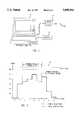
- FIG. 1is a view illustrating a portable computing device incorporating the present invention
- FIG. 2is a chart illustrating battery charging versus time according to the present invention
- FIG. 3is a schematic diagram illustrating circuitry of one embodiment of the present invention.
- a portable computer 10is shown.
- the computer 10may be connected to an AC adapter 12, which is in turn connected to a power source (not shown).
- a battery pack 14is also shown which resides within the computer 10.
- the AC adapter 12converts AC power into DC power that can be used to power the computer 10, or to charge the battery pack 14.
- the AC adaptereither charges the battery pack 14 when the computer 10 is off, or supplies power to the computer 10 when the computer is on.
- the AC adapterprovides a small fixed current to the battery pack 14 when the computer 10 is on, and a second fixed current when the computer 10 is off what is discussed below, with reference to FIG.'s 2-3, is a variable rate battery charger that adapts to the changing load requirements of a portable device, and utilizes all available power from the AC adapter to charge the battery pack.
- a chart 20is shown which illustrates a typical charge cycle for a battery pack within a portable device which incorporates the present invention.
- the chartprovides a relative time scale on the x-axis with time periods designated as t1, t2, t3, etc., and a y-axis indicating power in watts. It should be understood that the time periods indicated do not reflect absolute time, but rather, are simply indicators of changed conditions during a charge cycle. Note: the elements of the present invention will be discussed below, in reference to FIG. 3.
- An AC adapter 12is provided which has a maximum power output specified as 65 watts. To allow a margin of error, a maximum output power for the AC adapter 12 is set at 60 watts.
- a portable computer 10which incorporates power management features present in many of the computers on the market today. Power management features allow the computer 10 to power off particular subsystems that are not being used, thus conserving power, and later power these subsystems back on.
- An example of a subsystemwould be a hard disk, an LCD monitor, a CPU, or memory.
- a battery pack 14is inserted into the computer 10.
- the battery pack 14is fully drained, and therefore attempts to draw infinite current.
- the present inventionlimits the charge current to 3 amps. If the battery pack is at 10 volts, the power into the battery pack is 30 watts. The present invention provides the required 30 watts to the battery pack 14 during t2.
- the portable computer 10is turned on.
- the portable computer 10requires 25 watts of power from the AC adapter, and such power is provided.
- the voltage of the battery pack 14may have increased to say 12 volts.
- the battery pack 14therefore desires to draw 36 watts of power from the ac adapter (3 amps ⁇ 12 volts).
- the portable computer 10is drawing 25 watts, only 35 watts of power is available to the battery pack 14, and such is provided.
- a first subsystem (not shown) within the computer 10is powered down.
- the computer 10now requires only 20 watts of power for operation.
- the voltage of the battery pack 14has reached 14 volts, for example.
- the battery pack 14therefore desires to draw 3 amps ⁇ 14 volts, or 42 watts.
- the present inventionprovides all available power, i.e., 40 watts, to the battery pack 14 for charging.
- a second subsystemwithin the computer 10 is powered down.
- the computer 10now requires only 10 watts of power for operation. This leaves 50 watts of power available for the battery pack 14 for charging.
- the voltage of the batteryhas reached 16 volts, for example.
- the battery pack 14therefore is allowed to draw 3 amps ⁇ 16 volts, or 48 watts of power for charging.
- the computer 10now requires 25 watts of power for operation. This leaves approximately 45 watts of power available for charging the battery pack 14. The battery pack 14 is still not fully charged, so the present invention provides the remaining 45 available watts from the AC adapter to the battery pack 14.
- the computer 10is powered off.
- the battery pack 14is still not fully charged, but neither is it fully drained, so its voltage level has increased, say to 16.5 volts.
- the battery pack 14is no longer drawing a full 3 amps. Rather, it is now drawing approximately 2.7 amps.
- the AC adapternow provides approximately 45 watts to the battery pack 14.
- the battery pack 14is becoming fully charged. Its voltage is approaching 16.8 volts, but it is now drawing less than 1 amp of current.
- the AC adaptertherefore provides 16 watts to the battery pack.
- the present inventionadaptively provides to the battery pack 14 the maximum available power from the AC adapter 12, that is not required by the computer 10. As the power demands from the computer 10 increase, the power supplied to the battery pack 14 decreases. As the power demands from the computer 10 decrease, the available power to the battery pack 14 increases.
- FIG. 3For a more detailed discussion of an embodiment of the present invention that performs the functionality discussed above, refer now to FIG. 3.
- an adaptive battery charging apparatus 30is schematically shown.
- a battery 40is provided which is specified with a maximum charge current of 3 amps, and a fully charged voltage equal to 16.8 volts. It should be understood by one skilled in the art that the specified charge current, and fully charged voltage, are for illustrative purposes only, and may vary depending on the type of battery that is used.
- the charging apparatus 30is electrically connected to a DC source 32.
- the DC source 32may be derived from the output of an AC adapter, or by other conventional means.
- Currentflows from the DC source 32, through a current sense resistor 34, and onto a power line 36, to supply power to a portable device (not shown).
- the voltage at the output of resistor 34is termed V in .
- current through the resistor 34flows into a gated FET 38 for providing power to the battery 40.
- the FET 38is gated by a modulator 42 which regulates the output of the FET 38 via control line 44.
- the output of the FET 38is a modulated pulse train which is transmitted, via line 46, through an LC filter 48.
- the output of the LC filter 48is approximately a DC voltage at node 50 termed V o .
- V ois provided to the battery 40 to charge the battery 40.
- a current sense resistor 52Across the LC filter 48 is a current sense resistor 52.
- Each node of the current sense resistor 52is connected to a current sense amplifier 54.
- the current sense amplifiersenses the current that is being provided to the battery 40.
- the current sense amplifierprovides an output signal 56 which is fed into the modulator 42.
- the maximum current that the battery 40 should drawis 3 amps.
- the current sense amplifier 54is referenced such that if the battery 40 attempts to draw more than 3 amps, the amplifier 54 provides a signal 56 to the modulator 42 to reduce the voltage at V o and thereby regulate the power provided from the FET 38 to the battery 40 at precisely 3 amps.
- a voltage sense amplifier 58is also provided which is connected to a resistive network 60 and a voltage reference 62. The output of the voltage sense amplifier 58 is provided on signal line 64 to the modulator 42.
- the voltage reference 62is set to 16.8 volts, i.e., the voltage of the fully charged battery 40.
- the voltage sense amplifier 58signals the modulator 42 to reduce the duty cycle of the pulse width output of the FET 38 to keep V o from exceeding 16.8 volts.
- An input power sense amplifier 66is connected to both nodes of the current sense resistor 34. Since the voltage from the DC source 32 is constant, the power provided to the battery 40 and the portable device can be calculated using the equation:
- Vequals the voltage at V in and I equals the current through the current sense resistor 34.
- the maximum power available from the DC source 32is 60 watts. So, a reference point is set for the input power sense amplifier 66 such that it generates a control signal on line 68 to the modulator 42 to indicate when the power provided to the system approaches 60 watts.
- the modulator 42regulates the pulse train of the FET 38 to regulate the power input to the battery, plus the power drawn from the portable device, at 60 watts, or less.
- the adaptive battery charging apparatus 30power is provided from the DC source 32 to a portable device, and the portable device draws whatever power it needs from the DC source, up to 60 watts.
- a battery 40draws power for charging from the DC source 32.
- the current sense amplifier 54 and the voltage sense amplifier 58provide control signals to the modulator 42 to regulate the power that is provided to the battery 40 according to predefined voltage and current specifications for the battery 40.
- Such regulationas provided by the charging apparatus 30, allows the battery 40 to always charge using the maximum available power rather than at some predefined trickle charge current. This provides the most efficient charge time for the available power.
- the modulator 42 and the FET 38could be any device capable of receiving control signals, and from the control signals, regulating a power output. Once such device could be a microcontroller which reads in the control signals from lines 56, 64 and 68, and provides an output which regulates the power at node 46.
- the current sense amplifier 54 and the voltage sense amplifier 58may be replaced with any means for regulating voltage and current to the battery 40 to allow the battery 40 to be charged within its predetermined charge specifications.
- the present inventionprovides a system which allows a battery to be charged in the smallest amount of time for a given power capability of the AC adapter, whether the AC adapter is providing power just to the battery, or also to a portable device.
Landscapes
- Engineering & Computer Science (AREA)
- Theoretical Computer Science (AREA)
- Power Engineering (AREA)
- Physics & Mathematics (AREA)
- General Engineering & Computer Science (AREA)
- General Physics & Mathematics (AREA)
- Business, Economics & Management (AREA)
- Emergency Management (AREA)
- Charge And Discharge Circuits For Batteries Or The Like (AREA)
Abstract
Description
P=VI
Claims (4)
Priority Applications (3)
| Application Number | Priority Date | Filing Date | Title |
|---|---|---|---|
| US08/546,458US5698964A (en) | 1995-10-20 | 1995-10-20 | Adaptive power battery charging apparatus |
| US08/974,128US5939862A (en) | 1995-10-20 | 1997-11-19 | Adaptive power battery charging apparatus |
| US09/290,089US6127809A (en) | 1995-10-20 | 1999-04-12 | Adaptive power battery charging apparatus |
Applications Claiming Priority (1)
| Application Number | Priority Date | Filing Date | Title |
|---|---|---|---|
| US08/546,458US5698964A (en) | 1995-10-20 | 1995-10-20 | Adaptive power battery charging apparatus |
Related Child Applications (1)
| Application Number | Title | Priority Date | Filing Date |
|---|---|---|---|
| US08/974,128ContinuationUS5939862A (en) | 1995-10-20 | 1997-11-19 | Adaptive power battery charging apparatus |
Publications (1)
| Publication Number | Publication Date |
|---|---|
| US5698964Atrue US5698964A (en) | 1997-12-16 |
Family
ID=24180509
Family Applications (3)
| Application Number | Title | Priority Date | Filing Date |
|---|---|---|---|
| US08/546,458Expired - LifetimeUS5698964A (en) | 1995-10-20 | 1995-10-20 | Adaptive power battery charging apparatus |
| US08/974,128Expired - LifetimeUS5939862A (en) | 1995-10-20 | 1997-11-19 | Adaptive power battery charging apparatus |
| US09/290,089Expired - LifetimeUS6127809A (en) | 1995-10-20 | 1999-04-12 | Adaptive power battery charging apparatus |
Family Applications After (2)
| Application Number | Title | Priority Date | Filing Date |
|---|---|---|---|
| US08/974,128Expired - LifetimeUS5939862A (en) | 1995-10-20 | 1997-11-19 | Adaptive power battery charging apparatus |
| US09/290,089Expired - LifetimeUS6127809A (en) | 1995-10-20 | 1999-04-12 | Adaptive power battery charging apparatus |
Country Status (1)
| Country | Link |
|---|---|
| US (3) | US5698964A (en) |
Cited By (42)
| Publication number | Priority date | Publication date | Assignee | Title |
|---|---|---|---|---|
| US5832388A (en)* | 1996-12-31 | 1998-11-03 | Motorola, Inc. | Portable radiotelephone device adapted to receive a variety of other portable devices |
| US5886499A (en)* | 1997-09-11 | 1999-03-23 | Space Systems/Loral, Inc. | Life extending operational regime for battery |
| US5936380A (en)* | 1997-09-12 | 1999-08-10 | Micron Electronics, Inc. | Alternative power for a portable computer via solar cells |
| US6052291A (en)* | 1997-12-08 | 2000-04-18 | International Business Machines Corporation | AC adaptor with power consumption reduction in unused state for a battery-operated electronic apparatus |
| US6058034A (en)* | 1998-10-19 | 2000-05-02 | Dell Usa Lp | Current converter and source identification and detection |
| US6104170A (en)* | 1998-12-23 | 2000-08-15 | Fairchild Semiconductor Corporation | Method and circuit for preventing oscillations in a battery charger |
| US6137265A (en)* | 1999-01-11 | 2000-10-24 | Dell Usa, L.P. | Adaptive fast charging of lithium-ion batteries |
| US6140801A (en)* | 1998-07-08 | 2000-10-31 | Kabushiki Kaisha Toyoda Jidoshokki Seisakusho | Circuit and method for charging a battery based on an allowable dissipation of a housing |
| US6144187A (en)* | 1998-11-12 | 2000-11-07 | Fairchild Semiconductor Corporation | Power measurement for adaptive battery charger |
| US6172891B1 (en) | 1999-03-26 | 2001-01-09 | Dell Usa, L.P. | AC voltage adapter with integrated DC voltage power supply connector |
| US6184660B1 (en) | 1998-03-26 | 2001-02-06 | Micro International, Ltd. | High-side current-sensing smart battery charger |
| US6191552B1 (en) | 1999-01-25 | 2001-02-20 | Dell Usa, L.P. | External universal battery charging apparatus and method |
| US6194867B1 (en) | 1999-01-22 | 2001-02-27 | Dell Usa, L.P. | Adaptive multiple battery charging apparatus |
| US6204637B1 (en) | 1999-03-16 | 2001-03-20 | International Business Machines Corporation | Method and system for remotely supplying power through an automated power adapter to a data processing system |
| US6246215B1 (en) | 1999-03-08 | 2001-06-12 | O2 Micro International Limited | Buffer battery power supply system |
| US6300944B1 (en)* | 1997-09-12 | 2001-10-09 | Micron Technology, Inc. | Alternative power for a portable computer via solar cells |
| US6307377B1 (en) | 1999-11-05 | 2001-10-23 | Dell Usa, L.P. | Battery charge determination |
| US6452364B1 (en) | 1999-04-09 | 2002-09-17 | Fujitsu Limited | Battery charge control circuit, battery charging device, and battery charge control method |
| US6498461B1 (en) | 2001-08-17 | 2002-12-24 | O2 Micro International Limited | Voltage mode, high accuracy battery charger |
| US6597153B1 (en) | 2002-06-03 | 2003-07-22 | O2Micro International Limited | Fast transient charging circuit |
| US20040076812A1 (en)* | 2002-05-22 | 2004-04-22 | Wang Swei Mu | Three-dimensional foamable structure with wear-resistant feature |
| US20040080892A1 (en)* | 2002-10-24 | 2004-04-29 | Vlad Popescu-Stanesti | Battery over voltage and over current protection circuit and adjustable adapter current limit circuit |
| US20040080891A1 (en)* | 2002-10-24 | 2004-04-29 | You-Yuh Shyr | DC to DC controller with inrush current protection |
| US20040113585A1 (en)* | 2001-08-17 | 2004-06-17 | Stanesti Vlad Popescu | Charging circuit for parallel charging in multiple battery systems |
| US20040155627A1 (en)* | 2003-02-11 | 2004-08-12 | Stanesti Vlad Popescu | Selector circuit for power management in multiple battery systems |
| US6861824B1 (en) | 2002-07-10 | 2005-03-01 | Arquesttechnology, Inc. | Charger system with dual-level current regulation and dual-level thermal regulation |
| US6873322B2 (en) | 2002-06-07 | 2005-03-29 | 02Micro International Limited | Adaptive LCD power supply circuit |
| US6888338B1 (en) | 2003-01-27 | 2005-05-03 | O2Micro International Limited | Portable computer and docking station having charging circuits with remote power sensing capabilities |
| US20050189916A1 (en)* | 2001-08-17 | 2005-09-01 | Constantin Bucur | Power management circuit |
| US7095217B1 (en) | 2005-03-31 | 2006-08-22 | O2Micro International Limited | Method circuitry and electronic device for controlling a variable output dc power source |
| US20060186868A1 (en)* | 2005-02-23 | 2006-08-24 | Nec Corporation | Current control circuit with limiter, temperature control circuit, and brightness control circuit |
| US20060226813A1 (en)* | 2005-04-08 | 2006-10-12 | Chun Lu | Sense amplifier for use with wake-up charging current |
| US20070016806A1 (en)* | 2005-07-13 | 2007-01-18 | Roberto Prosperi | Apparatus and methods for information handling system with power supply device with variable output power |
| CN100367594C (en)* | 2003-05-08 | 2008-02-06 | 美国凹凸微系有限公司 | DC to DC controller with inrush current protection |
| US20090278499A1 (en)* | 2000-09-21 | 2009-11-12 | O2Micro, Inc. | Method and electronic circuit for efficient battery wake up charging |
| US7791314B2 (en) | 2000-09-21 | 2010-09-07 | O2Micro International Limited | Power management topologies to control power between a DC power source and one or more batteries to a system load |
| US20100237845A1 (en)* | 2009-03-19 | 2010-09-23 | Dialog Semiconductor Gmbh | Charge current reduction for current limited switched power supply |
| USRE42114E1 (en) | 1994-12-26 | 2011-02-08 | Fujitsu Semiconductor Limited | Control system for charging batteries and electronic apparatus using same |
| US20120268974A1 (en)* | 2011-04-22 | 2012-10-25 | Hamilton Sundstrand Corporation | High-resolution and low-resolution sensors for phase detection |
| US20130307464A1 (en)* | 2012-05-16 | 2013-11-21 | Zuohang Zhu | Portable Battery Charger |
| US10302691B2 (en)* | 2012-02-22 | 2019-05-28 | Renault S.A.S. | Method and system for estimating the insulation resistance between a battery and an electrical earth |
| EP3940919A4 (en)* | 2020-05-22 | 2023-04-05 | Huawei Digital Power Technologies Co., Ltd. | CHARGING CONTROL METHOD, ENERGY STORAGE MODULE AND ELECTRICAL DEVICE |
Families Citing this family (49)
| Publication number | Priority date | Publication date | Assignee | Title |
|---|---|---|---|---|
| US6222347B1 (en)* | 1998-04-30 | 2001-04-24 | Apple Computer, Inc. | System for charging portable computer's battery using both the dynamically determined power available based on power consumed by sub-system devices and power limits from the battery |
| US6253988B1 (en)* | 1999-03-29 | 2001-07-03 | Antaya Technologies Corporation | Low temperature solder |
| US6300744B1 (en) | 2000-02-10 | 2001-10-09 | Siliconix Incorporated | High-efficiency battery charger |
| US6498460B1 (en)* | 2001-12-14 | 2002-12-24 | Compaq Information Technologies Group, L.P. | Prioritization-based power management protocol in a computer system |
| JP3785377B2 (en)* | 2002-03-29 | 2006-06-14 | インターナショナル・ビジネス・マシーンズ・コーポレーション | Electric device, computer apparatus, intelligent battery, and AC adapter confirmation method |
| KR100481505B1 (en)* | 2003-01-02 | 2005-04-07 | 삼성전자주식회사 | Digital device capable of battery charging and method thereof |
| US7102415B1 (en)* | 2004-03-26 | 2006-09-05 | National Semiconductor Corporation | Trip-point detection circuit |
| US7526659B2 (en) | 2005-02-01 | 2009-04-28 | Hewlett-Packard Development Company, L.P. | Systems and methods for controlling use of power in a computer system |
| US7489105B2 (en)* | 2005-03-21 | 2009-02-10 | Eveready Battery Company, Inc. | Portable power supply |
| US20070241721A1 (en)* | 2005-03-21 | 2007-10-18 | Eveready Battery Company, Inc. | Direct current power supply |
| US20070279895A1 (en)* | 2005-05-12 | 2007-12-06 | Finelite | Workspace lighting system |
| US7701173B2 (en)* | 2005-12-13 | 2010-04-20 | Research In Motion Limited | Charging and power supply for mobile devices |
| US7531986B2 (en) | 2006-02-23 | 2009-05-12 | Eveready Battery Company, Inc. | Power supply for battery powered devices |
| US20070236171A1 (en)* | 2006-03-31 | 2007-10-11 | Li Peter T | Battery conditioning |
| WO2008092056A1 (en)* | 2007-01-25 | 2008-07-31 | Eveready Battery Company, Inc. | Portable power supply |
| WO2008092087A1 (en)* | 2007-01-25 | 2008-07-31 | Eveready Battery Company, Inc. | Use extender device |
| US20080231226A1 (en)* | 2007-03-23 | 2008-09-25 | Eveready Battery Company, Inc. | Battery Powered Device |
| EP2244349A1 (en)* | 2009-04-22 | 2010-10-27 | FRIWO Gerätebau GmbH | Battery charger and method for charging a battery |
| US9847636B2 (en) | 2012-10-03 | 2017-12-19 | Ideal Industries, Inc. | Low voltage buss system |
| CA2768397A1 (en)* | 2009-07-24 | 2011-01-27 | Access Business Group International Llc | Power supply |
| TWI406474B (en)* | 2009-12-02 | 2013-08-21 | 廣達電腦股份有限公司 | Battery charge-discharge path management circuit and method thereof |
| US8577056B2 (en) | 2010-06-30 | 2013-11-05 | Intel Corporation | Limiting peak audio power in mobile devices |
| US8228038B2 (en)* | 2009-12-23 | 2012-07-24 | Intel Corporation | Power management control system and method |
| US8069356B2 (en) | 2010-01-06 | 2011-11-29 | Apple Inc. | Accessory power management |
| US8368355B2 (en) | 2010-04-14 | 2013-02-05 | Apple Inc. | Portable electronic device power manager with current limit feedback control loop modification for stabilizing an external power supply |
| WO2011146783A1 (en) | 2010-05-21 | 2011-11-24 | Qnovo Inc. | Method and circuitry to adaptively charge a battery/cell |
| US12081057B2 (en) | 2010-05-21 | 2024-09-03 | Qnovo Inc. | Method and circuitry to adaptively charge a battery/cell |
| US8970178B2 (en) | 2010-06-24 | 2015-03-03 | Qnovo Inc. | Method and circuitry to calculate the state of charge of a battery/cell |
| US11397215B2 (en) | 2010-05-21 | 2022-07-26 | Qnovo Inc. | Battery adaptive charging using battery physical phenomena |
| US11397216B2 (en) | 2010-05-21 | 2022-07-26 | Qnovo Inc. | Battery adaptive charging using a battery model |
| US8791669B2 (en) | 2010-06-24 | 2014-07-29 | Qnovo Inc. | Method and circuitry to calculate the state of charge of a battery/cell |
| US10389156B2 (en) | 2010-05-21 | 2019-08-20 | Qnovo Inc. | Method and circuitry to adaptively charge a battery/cell |
| US9142994B2 (en) | 2012-09-25 | 2015-09-22 | Qnovo, Inc. | Method and circuitry to adaptively charge a battery/cell |
| US10067198B2 (en) | 2010-05-21 | 2018-09-04 | Qnovo Inc. | Method and circuitry to adaptively charge a battery/cell using the state of health thereof |
| US11791647B2 (en) | 2010-05-21 | 2023-10-17 | Qnovo Inc. | Method and circuitry to adaptively charge a battery/cell |
| US8650419B2 (en)* | 2010-12-20 | 2014-02-11 | Hitachi, Ltd. | Storage apparatus and its control method |
| US8612782B2 (en) | 2011-03-31 | 2013-12-17 | Intel Corporation | System and method for determining multiple power levels of the sub-systems based on a detected available power and prestored power setting information of a plurality of different combinations of the sub-systems |
| US9564772B2 (en) | 2011-04-25 | 2017-02-07 | Intersil Americas LLC | Charging system with adaptive power management |
| US9190868B2 (en) | 2011-05-06 | 2015-11-17 | Ford Global Technologies, Llc | Vehicle and method for charging vehicle batteries |
| TWI456863B (en)* | 2011-12-28 | 2014-10-11 | Twinhead Int Corp | Series-type charging device and charging method thereof |
| US9912100B2 (en) | 2012-10-03 | 2018-03-06 | Ideal Industries, Inc. | Low voltage buss system |
| US10186801B2 (en) | 2012-10-03 | 2019-01-22 | Ideal Industries, Inc. | Low voltage buss system |
| US9063018B1 (en) | 2012-10-22 | 2015-06-23 | Qnovo Inc. | Method and circuitry to determine temperature and/or state of health of a battery/cell |
| US9461492B1 (en) | 2013-04-19 | 2016-10-04 | Qnovo Inc. | Method and circuitry to adaptively charge a battery/cell using a charge-time parameter |
| US9594415B2 (en) | 2013-09-22 | 2017-03-14 | Microsoft Technology Licensing, Llc | Accessory device power management |
| US9588563B2 (en) | 2014-05-30 | 2017-03-07 | Apple Inc. | Protocol for managing a controllable power adapter accessory |
| US10574079B1 (en) | 2014-06-20 | 2020-02-25 | Qnovo Inc. | Wireless charging techniques and circuitry for a battery |
| US10108245B2 (en) | 2016-04-11 | 2018-10-23 | Microsoft Technology Licensing, Llc | Interaction based charging control |
| US20240222721A1 (en)* | 2018-11-07 | 2024-07-04 | Qnovo Inc. | Battery adaptive charging using battery physical phenomena |
Citations (6)
| Publication number | Priority date | Publication date | Assignee | Title |
|---|---|---|---|---|
| US5239495A (en)* | 1989-06-23 | 1993-08-24 | Kabushiki Kaisha Toshiba | Power supply control system for a portable computer |
| US5349282A (en)* | 1990-12-11 | 1994-09-20 | Span, Inc. | Battery charging and monitoring system |
| US5465039A (en)* | 1992-09-16 | 1995-11-07 | International Business Machines Corporation | Power supply for electronic device, and electronic device system |
| US5523670A (en)* | 1990-11-07 | 1996-06-04 | Kabushiki Kaisha Toshiba | Method and apparatus for controlling power supply |
| US5532935A (en)* | 1991-10-02 | 1996-07-02 | Kabushiki Kaisha Toshiba | Electronic device capable of automatically controlling power assumption of components employed in accordance with operating time period by user |
| US5532524A (en)* | 1994-05-11 | 1996-07-02 | Apple Computer, Inc. | Distributed power regulation in a portable computer to optimize heat dissipation and maximize battery run-time for various power modes |
Family Cites Families (7)
| Publication number | Priority date | Publication date | Assignee | Title |
|---|---|---|---|---|
| US4384214A (en)* | 1981-08-03 | 1983-05-17 | Integrated Switching Supplies, Inc. | Non-interrupting power supplies for loads of less than 500 watts |
| US4885523A (en)* | 1988-03-15 | 1989-12-05 | Norand Corporation | Battery conditioning system having communication with battery parameter memory means in conjunction with battery conditioning |
| US4843299A (en)* | 1987-06-01 | 1989-06-27 | Power-Tech Systems Corporation | Universal battery charging system and a method |
| GB8910193D0 (en)* | 1989-05-04 | 1989-06-21 | Astec Int Ltd | Improvements in power supplies |
| US5382893A (en)* | 1991-05-16 | 1995-01-17 | Compaq Computer Corporation | Maximum power regulated battery charger |
| US5418445A (en)* | 1992-08-26 | 1995-05-23 | Tele Digital Development, Inc. | Switching circuit for simultaneous rapid battery charge and system operation |
| US5629604A (en)* | 1992-11-13 | 1997-05-13 | Zenith Data Systems Corporation | Computer power supply system |
- 1995
- 1995-10-20USUS08/546,458patent/US5698964A/ennot_activeExpired - Lifetime
- 1997
- 1997-11-19USUS08/974,128patent/US5939862A/ennot_activeExpired - Lifetime
- 1999
- 1999-04-12USUS09/290,089patent/US6127809A/ennot_activeExpired - Lifetime
Patent Citations (6)
| Publication number | Priority date | Publication date | Assignee | Title |
|---|---|---|---|---|
| US5239495A (en)* | 1989-06-23 | 1993-08-24 | Kabushiki Kaisha Toshiba | Power supply control system for a portable computer |
| US5523670A (en)* | 1990-11-07 | 1996-06-04 | Kabushiki Kaisha Toshiba | Method and apparatus for controlling power supply |
| US5349282A (en)* | 1990-12-11 | 1994-09-20 | Span, Inc. | Battery charging and monitoring system |
| US5532935A (en)* | 1991-10-02 | 1996-07-02 | Kabushiki Kaisha Toshiba | Electronic device capable of automatically controlling power assumption of components employed in accordance with operating time period by user |
| US5465039A (en)* | 1992-09-16 | 1995-11-07 | International Business Machines Corporation | Power supply for electronic device, and electronic device system |
| US5532524A (en)* | 1994-05-11 | 1996-07-02 | Apple Computer, Inc. | Distributed power regulation in a portable computer to optimize heat dissipation and maximize battery run-time for various power modes |
Non-Patent Citations (2)
| Title |
|---|
| Free, John, "Rechargeable Lithium Batteries," Copy in group 2100 Library from Popular Science magazine, Dec. 1985. |
| Free, John, Rechargeable Lithium Batteries, Copy in group 2100 Library from Popular Science magazine, Dec. 1985.* |
Cited By (61)
| Publication number | Priority date | Publication date | Assignee | Title |
|---|---|---|---|---|
| USRE42114E1 (en) | 1994-12-26 | 2011-02-08 | Fujitsu Semiconductor Limited | Control system for charging batteries and electronic apparatus using same |
| USRE43911E1 (en) | 1994-12-26 | 2013-01-08 | Fujitsu Semiconductor Limited | Control system for charging batteries and electronic apparatus using same |
| US5832388A (en)* | 1996-12-31 | 1998-11-03 | Motorola, Inc. | Portable radiotelephone device adapted to receive a variety of other portable devices |
| US5886499A (en)* | 1997-09-11 | 1999-03-23 | Space Systems/Loral, Inc. | Life extending operational regime for battery |
| US6300944B1 (en)* | 1997-09-12 | 2001-10-09 | Micron Technology, Inc. | Alternative power for a portable computer via solar cells |
| US5936380A (en)* | 1997-09-12 | 1999-08-10 | Micron Electronics, Inc. | Alternative power for a portable computer via solar cells |
| US6445376B2 (en) | 1997-09-12 | 2002-09-03 | Sean T. Parrish | Alternative power for a portable computer via solar cells |
| US6052291A (en)* | 1997-12-08 | 2000-04-18 | International Business Machines Corporation | AC adaptor with power consumption reduction in unused state for a battery-operated electronic apparatus |
| US6184660B1 (en) | 1998-03-26 | 2001-02-06 | Micro International, Ltd. | High-side current-sensing smart battery charger |
| US6140801A (en)* | 1998-07-08 | 2000-10-31 | Kabushiki Kaisha Toyoda Jidoshokki Seisakusho | Circuit and method for charging a battery based on an allowable dissipation of a housing |
| US6058034A (en)* | 1998-10-19 | 2000-05-02 | Dell Usa Lp | Current converter and source identification and detection |
| US6144187A (en)* | 1998-11-12 | 2000-11-07 | Fairchild Semiconductor Corporation | Power measurement for adaptive battery charger |
| US6104170A (en)* | 1998-12-23 | 2000-08-15 | Fairchild Semiconductor Corporation | Method and circuit for preventing oscillations in a battery charger |
| US6137265A (en)* | 1999-01-11 | 2000-10-24 | Dell Usa, L.P. | Adaptive fast charging of lithium-ion batteries |
| US6194867B1 (en) | 1999-01-22 | 2001-02-27 | Dell Usa, L.P. | Adaptive multiple battery charging apparatus |
| US6191552B1 (en) | 1999-01-25 | 2001-02-20 | Dell Usa, L.P. | External universal battery charging apparatus and method |
| US6337557B1 (en)* | 1999-01-25 | 2002-01-08 | Barry K. Kates | External universal battery charging apparatus and method |
| US6246215B1 (en) | 1999-03-08 | 2001-06-12 | O2 Micro International Limited | Buffer battery power supply system |
| US6204637B1 (en) | 1999-03-16 | 2001-03-20 | International Business Machines Corporation | Method and system for remotely supplying power through an automated power adapter to a data processing system |
| US6172891B1 (en) | 1999-03-26 | 2001-01-09 | Dell Usa, L.P. | AC voltage adapter with integrated DC voltage power supply connector |
| US6452364B1 (en) | 1999-04-09 | 2002-09-17 | Fujitsu Limited | Battery charge control circuit, battery charging device, and battery charge control method |
| US6307377B1 (en) | 1999-11-05 | 2001-10-23 | Dell Usa, L.P. | Battery charge determination |
| US8350534B2 (en) | 2000-09-21 | 2013-01-08 | O2Micro International, Ltd. | Method and electronic circuit for efficient battery wake up charging |
| US8120312B2 (en) | 2000-09-21 | 2012-02-21 | 02Micro International Limited | Power management topologies to control power between a DC power source and one or more batteries to a system load |
| US20090278499A1 (en)* | 2000-09-21 | 2009-11-12 | O2Micro, Inc. | Method and electronic circuit for efficient battery wake up charging |
| US7791314B2 (en) | 2000-09-21 | 2010-09-07 | O2Micro International Limited | Power management topologies to control power between a DC power source and one or more batteries to a system load |
| US20100327813A1 (en)* | 2000-09-21 | 2010-12-30 | O2Micro International Limited | Power management topologies |
| US20040113585A1 (en)* | 2001-08-17 | 2004-06-17 | Stanesti Vlad Popescu | Charging circuit for parallel charging in multiple battery systems |
| US6861823B2 (en) | 2001-08-17 | 2005-03-01 | O2Micro International Limited | Charging circuit for controlling a charging parameter of a rechargeable battery |
| US7202634B2 (en) | 2001-08-17 | 2007-04-10 | O2Micro International Limited | Voltage mode, high accuracy battery charger |
| US6611129B2 (en)* | 2001-08-17 | 2003-08-26 | O2Micro International Limited | Voltage mode, high accuracy battery charger |
| US20050189916A1 (en)* | 2001-08-17 | 2005-09-01 | Constantin Bucur | Power management circuit |
| US6498461B1 (en) | 2001-08-17 | 2002-12-24 | O2 Micro International Limited | Voltage mode, high accuracy battery charger |
| US7064521B2 (en) | 2001-08-17 | 2006-06-20 | O2Micro International Limited | Charging circuit for parallel charging in multiple battery systems |
| US20040076812A1 (en)* | 2002-05-22 | 2004-04-22 | Wang Swei Mu | Three-dimensional foamable structure with wear-resistant feature |
| US6597153B1 (en) | 2002-06-03 | 2003-07-22 | O2Micro International Limited | Fast transient charging circuit |
| US6873322B2 (en) | 2002-06-07 | 2005-03-29 | 02Micro International Limited | Adaptive LCD power supply circuit |
| US6861824B1 (en) | 2002-07-10 | 2005-03-01 | Arquesttechnology, Inc. | Charger system with dual-level current regulation and dual-level thermal regulation |
| US6989981B2 (en) | 2002-10-24 | 2006-01-24 | 02Micro International Limited | Battery over voltage and over protection circuit and adjustable adapter current limit circuit |
| US20040080892A1 (en)* | 2002-10-24 | 2004-04-29 | Vlad Popescu-Stanesti | Battery over voltage and over current protection circuit and adjustable adapter current limit circuit |
| US20040080891A1 (en)* | 2002-10-24 | 2004-04-29 | You-Yuh Shyr | DC to DC controller with inrush current protection |
| US7203048B2 (en) | 2002-10-24 | 2007-04-10 | 02Micro International Limited | DC to DC controller with inrush current protection |
| US6888338B1 (en) | 2003-01-27 | 2005-05-03 | O2Micro International Limited | Portable computer and docking station having charging circuits with remote power sensing capabilities |
| US20040155627A1 (en)* | 2003-02-11 | 2004-08-12 | Stanesti Vlad Popescu | Selector circuit for power management in multiple battery systems |
| US6879134B2 (en) | 2003-02-11 | 2005-04-12 | O2Micro International Limited | Selector circuit for power management in multiple battery systems |
| CN100367594C (en)* | 2003-05-08 | 2008-02-06 | 美国凹凸微系有限公司 | DC to DC controller with inrush current protection |
| US7420408B2 (en)* | 2005-02-23 | 2008-09-02 | Nec Corporation | Current control circuit with limiter, temperature control circuit, and brightness control circuit |
| US20060186868A1 (en)* | 2005-02-23 | 2006-08-24 | Nec Corporation | Current control circuit with limiter, temperature control circuit, and brightness control circuit |
| US7095217B1 (en) | 2005-03-31 | 2006-08-22 | O2Micro International Limited | Method circuitry and electronic device for controlling a variable output dc power source |
| US7268520B2 (en) | 2005-04-08 | 2007-09-11 | O2Micro International Limited | Sense amplifier for use with wake-up charging current |
| US20060226813A1 (en)* | 2005-04-08 | 2006-10-12 | Chun Lu | Sense amplifier for use with wake-up charging current |
| US20070016806A1 (en)* | 2005-07-13 | 2007-01-18 | Roberto Prosperi | Apparatus and methods for information handling system with power supply device with variable output power |
| US7363522B2 (en) | 2005-07-13 | 2008-04-22 | Dell Products L.P. | Apparatus and methods for information handling system with power supply device with variable output power |
| US8513920B2 (en)* | 2009-03-19 | 2013-08-20 | Dialog Semiconductor Gmbh. | Charge current reduction for current limited switched power supply |
| US20100237845A1 (en)* | 2009-03-19 | 2010-09-23 | Dialog Semiconductor Gmbh | Charge current reduction for current limited switched power supply |
| US20120268974A1 (en)* | 2011-04-22 | 2012-10-25 | Hamilton Sundstrand Corporation | High-resolution and low-resolution sensors for phase detection |
| US8643318B2 (en)* | 2011-04-22 | 2014-02-04 | Hamilton Sundstrand Corporation | High-resolution and low-resolution sensors for phase detection |
| US10302691B2 (en)* | 2012-02-22 | 2019-05-28 | Renault S.A.S. | Method and system for estimating the insulation resistance between a battery and an electrical earth |
| US20130307464A1 (en)* | 2012-05-16 | 2013-11-21 | Zuohang Zhu | Portable Battery Charger |
| US9093855B2 (en)* | 2012-05-16 | 2015-07-28 | Powerstick.Com Inc. | Portable battery charger |
| EP3940919A4 (en)* | 2020-05-22 | 2023-04-05 | Huawei Digital Power Technologies Co., Ltd. | CHARGING CONTROL METHOD, ENERGY STORAGE MODULE AND ELECTRICAL DEVICE |
Also Published As
| Publication number | Publication date |
|---|---|
| US5939862A (en) | 1999-08-17 |
| US6127809A (en) | 2000-10-03 |
Similar Documents
| Publication | Publication Date | Title |
|---|---|---|
| US5698964A (en) | Adaptive power battery charging apparatus | |
| US9231435B2 (en) | Methods and apparatuses for operating devices with solar power | |
| US7868582B2 (en) | Portable devices having multiple power interfaces | |
| US6833686B2 (en) | Circuit and method of operation for an adaptive charge rate power supply | |
| US6337557B1 (en) | External universal battery charging apparatus and method | |
| EP0469533B1 (en) | Adapter for external battery and battery system | |
| US6384570B2 (en) | Battery pack and charge circuit therefor | |
| EP1225674B1 (en) | Portable electronic apparatus, charging apparatus and method thereof | |
| TW418558B (en) | Dynamic regulator for a DC-to-DC power converter and related methods | |
| US5576609A (en) | Constant power dissipation control of a linear pass element used for battery charging | |
| US6049141A (en) | Device and a method allowing multiple batteries to share a common load | |
| US20040108833A1 (en) | Universal battery | |
| KR20080027830A (en) | Multi-critical Charging of Rechargeable Batteries | |
| WO1994007293A1 (en) | Method and apparatus for charging a battery powered electronic device | |
| MXPA98000674A (en) | Bate charger system | |
| CN100409534C (en) | Voltage/current regulator and method for charging battery | |
| US5793187A (en) | System and method for increasing the available energy in non-rechargeable batteries | |
| CN1118917C (en) | Control device and method for changing charging current with system load | |
| JPH11187587A (en) | Charge control circuit | |
| EP3674844B1 (en) | Circuit and method of operation for an adaptive charge rate power supply | |
| CN114629187B (en) | Charging control method and device, and electronic equipment | |
| CN112202234B (en) | Power management circuit and electronic equipment | |
| CN213521410U (en) | Smart Solar Charge Control System | |
| CA2419497C (en) | Circuit and method of operation for an adaptive charge rate power supply | |
| CN100578885C (en) | Electronic device with adjustable voltage |
Legal Events
| Date | Code | Title | Description |
|---|---|---|---|
| AS | Assignment | Owner name:DELL USA, L.P., TEXAS Free format text:ASSIGNMENT OF ASSIGNORS INTEREST;ASSIGNORS:KATES, BARRY K.;SHEEHAN, EDWWARD P. JR.;REEL/FRAME:007717/0253 Effective date:19951020 | |
| STCF | Information on status: patent grant | Free format text:PATENTED CASE | |
| CC | Certificate of correction | ||
| REMI | Maintenance fee reminder mailed | ||
| FPAY | Fee payment | Year of fee payment:4 | |
| SULP | Surcharge for late payment | ||
| FEPP | Fee payment procedure | Free format text:PAYOR NUMBER ASSIGNED (ORIGINAL EVENT CODE: ASPN); ENTITY STATUS OF PATENT OWNER: LARGE ENTITY | |
| FPAY | Fee payment | Year of fee payment:8 | |
| FPAY | Fee payment | Year of fee payment:12 | |
| AS | Assignment | Owner name:BANK OF AMERICA, N.A., AS ADMINISTRATIVE AGENT, TE Free format text:PATENT SECURITY AGREEMENT (ABL);ASSIGNORS:DELL INC.;APPASSURE SOFTWARE, INC.;ASAP SOFTWARE EXPRESS, INC.;AND OTHERS;REEL/FRAME:031898/0001 Effective date:20131029 Owner name:BANK OF NEW YORK MELLON TRUST COMPANY, N.A., AS FIRST LIEN COLLATERAL AGENT, TEXAS Free format text:PATENT SECURITY AGREEMENT (NOTES);ASSIGNORS:APPASSURE SOFTWARE, INC.;ASAP SOFTWARE EXPRESS, INC.;BOOMI, INC.;AND OTHERS;REEL/FRAME:031897/0348 Effective date:20131029 Owner name:BANK OF AMERICA, N.A., AS ADMINISTRATIVE AGENT, TEXAS Free format text:PATENT SECURITY AGREEMENT (ABL);ASSIGNORS:DELL INC.;APPASSURE SOFTWARE, INC.;ASAP SOFTWARE EXPRESS, INC.;AND OTHERS;REEL/FRAME:031898/0001 Effective date:20131029 Owner name:BANK OF AMERICA, N.A., AS COLLATERAL AGENT, NORTH CAROLINA Free format text:PATENT SECURITY AGREEMENT (TERM LOAN);ASSIGNORS:DELL INC.;APPASSURE SOFTWARE, INC.;ASAP SOFTWARE EXPRESS, INC.;AND OTHERS;REEL/FRAME:031899/0261 Effective date:20131029 Owner name:BANK OF AMERICA, N.A., AS COLLATERAL AGENT, NORTH Free format text:PATENT SECURITY AGREEMENT (TERM LOAN);ASSIGNORS:DELL INC.;APPASSURE SOFTWARE, INC.;ASAP SOFTWARE EXPRESS, INC.;AND OTHERS;REEL/FRAME:031899/0261 Effective date:20131029 Owner name:BANK OF NEW YORK MELLON TRUST COMPANY, N.A., AS FI Free format text:PATENT SECURITY AGREEMENT (NOTES);ASSIGNORS:APPASSURE SOFTWARE, INC.;ASAP SOFTWARE EXPRESS, INC.;BOOMI, INC.;AND OTHERS;REEL/FRAME:031897/0348 Effective date:20131029 | |
| AS | Assignment | Owner name:FORCE10 NETWORKS, INC., CALIFORNIA Free format text:RELEASE BY SECURED PARTY;ASSIGNOR:BANK OF AMERICA, N.A., AS ADMINISTRATIVE AGENT;REEL/FRAME:040065/0216 Effective date:20160907 Owner name:ASAP SOFTWARE EXPRESS, INC., ILLINOIS Free format text:RELEASE BY SECURED PARTY;ASSIGNOR:BANK OF AMERICA, N.A., AS ADMINISTRATIVE AGENT;REEL/FRAME:040065/0216 Effective date:20160907 Owner name:DELL SOFTWARE INC., CALIFORNIA Free format text:RELEASE BY SECURED PARTY;ASSIGNOR:BANK OF AMERICA, N.A., AS ADMINISTRATIVE AGENT;REEL/FRAME:040065/0216 Effective date:20160907 Owner name:DELL USA L.P., TEXAS Free format text:RELEASE BY SECURED PARTY;ASSIGNOR:BANK OF AMERICA, N.A., AS ADMINISTRATIVE AGENT;REEL/FRAME:040065/0216 Effective date:20160907 Owner name:DELL INC., TEXAS Free format text:RELEASE BY SECURED PARTY;ASSIGNOR:BANK OF AMERICA, N.A., AS ADMINISTRATIVE AGENT;REEL/FRAME:040065/0216 Effective date:20160907 Owner name:DELL PRODUCTS L.P., TEXAS Free format text:RELEASE BY SECURED PARTY;ASSIGNOR:BANK OF AMERICA, N.A., AS ADMINISTRATIVE AGENT;REEL/FRAME:040065/0216 Effective date:20160907 Owner name:WYSE TECHNOLOGY L.L.C., CALIFORNIA Free format text:RELEASE BY SECURED PARTY;ASSIGNOR:BANK OF AMERICA, N.A., AS ADMINISTRATIVE AGENT;REEL/FRAME:040065/0216 Effective date:20160907 Owner name:APPASSURE SOFTWARE, INC., VIRGINIA Free format text:RELEASE BY SECURED PARTY;ASSIGNOR:BANK OF AMERICA, N.A., AS ADMINISTRATIVE AGENT;REEL/FRAME:040065/0216 Effective date:20160907 Owner name:DELL MARKETING L.P., TEXAS Free format text:RELEASE BY SECURED PARTY;ASSIGNOR:BANK OF AMERICA, N.A., AS ADMINISTRATIVE AGENT;REEL/FRAME:040065/0216 Effective date:20160907 Owner name:PEROT SYSTEMS CORPORATION, TEXAS Free format text:RELEASE BY SECURED PARTY;ASSIGNOR:BANK OF AMERICA, N.A., AS ADMINISTRATIVE AGENT;REEL/FRAME:040065/0216 Effective date:20160907 Owner name:CREDANT TECHNOLOGIES, INC., TEXAS Free format text:RELEASE BY SECURED PARTY;ASSIGNOR:BANK OF AMERICA, N.A., AS ADMINISTRATIVE AGENT;REEL/FRAME:040065/0216 Effective date:20160907 Owner name:SECUREWORKS, INC., GEORGIA Free format text:RELEASE BY SECURED PARTY;ASSIGNOR:BANK OF AMERICA, N.A., AS ADMINISTRATIVE AGENT;REEL/FRAME:040065/0216 Effective date:20160907 Owner name:COMPELLANT TECHNOLOGIES, INC., MINNESOTA Free format text:RELEASE BY SECURED PARTY;ASSIGNOR:BANK OF AMERICA, N.A., AS ADMINISTRATIVE AGENT;REEL/FRAME:040065/0216 Effective date:20160907 | |
| AS | Assignment | Owner name:DELL PRODUCTS L.P., TEXAS Free format text:RELEASE BY SECURED PARTY;ASSIGNOR:BANK OF AMERICA, N.A., AS COLLATERAL AGENT;REEL/FRAME:040040/0001 Effective date:20160907 Owner name:APPASSURE SOFTWARE, INC., VIRGINIA Free format text:RELEASE BY SECURED PARTY;ASSIGNOR:BANK OF AMERICA, N.A., AS COLLATERAL AGENT;REEL/FRAME:040040/0001 Effective date:20160907 Owner name:DELL MARKETING L.P., TEXAS Free format text:RELEASE BY SECURED PARTY;ASSIGNOR:BANK OF AMERICA, N.A., AS COLLATERAL AGENT;REEL/FRAME:040040/0001 Effective date:20160907 Owner name:CREDANT TECHNOLOGIES, INC., TEXAS Free format text:RELEASE BY SECURED PARTY;ASSIGNOR:BANK OF AMERICA, N.A., AS COLLATERAL AGENT;REEL/FRAME:040040/0001 Effective date:20160907 Owner name:ASAP SOFTWARE EXPRESS, INC., ILLINOIS Free format text:RELEASE BY SECURED PARTY;ASSIGNOR:BANK OF AMERICA, N.A., AS COLLATERAL AGENT;REEL/FRAME:040040/0001 Effective date:20160907 Owner name:FORCE10 NETWORKS, INC., CALIFORNIA Free format text:RELEASE BY SECURED PARTY;ASSIGNOR:BANK OF AMERICA, N.A., AS COLLATERAL AGENT;REEL/FRAME:040040/0001 Effective date:20160907 Owner name:DELL USA L.P., TEXAS Free format text:RELEASE BY SECURED PARTY;ASSIGNOR:BANK OF AMERICA, N.A., AS COLLATERAL AGENT;REEL/FRAME:040040/0001 Effective date:20160907 Owner name:COMPELLENT TECHNOLOGIES, INC., MINNESOTA Free format text:RELEASE BY SECURED PARTY;ASSIGNOR:BANK OF AMERICA, N.A., AS COLLATERAL AGENT;REEL/FRAME:040040/0001 Effective date:20160907 Owner name:SECUREWORKS, INC., GEORGIA Free format text:RELEASE BY SECURED PARTY;ASSIGNOR:BANK OF AMERICA, N.A., AS COLLATERAL AGENT;REEL/FRAME:040040/0001 Effective date:20160907 Owner name:WYSE TECHNOLOGY L.L.C., CALIFORNIA Free format text:RELEASE BY SECURED PARTY;ASSIGNOR:BANK OF AMERICA, N.A., AS COLLATERAL AGENT;REEL/FRAME:040040/0001 Effective date:20160907 Owner name:DELL INC., TEXAS Free format text:RELEASE BY SECURED PARTY;ASSIGNOR:BANK OF AMERICA, N.A., AS COLLATERAL AGENT;REEL/FRAME:040040/0001 Effective date:20160907 Owner name:DELL SOFTWARE INC., CALIFORNIA Free format text:RELEASE BY SECURED PARTY;ASSIGNOR:BANK OF AMERICA, N.A., AS COLLATERAL AGENT;REEL/FRAME:040040/0001 Effective date:20160907 Owner name:PEROT SYSTEMS CORPORATION, TEXAS Free format text:RELEASE BY SECURED PARTY;ASSIGNOR:BANK OF AMERICA, N.A., AS COLLATERAL AGENT;REEL/FRAME:040040/0001 Effective date:20160907 Owner name:PEROT SYSTEMS CORPORATION, TEXAS Free format text:RELEASE BY SECURED PARTY;ASSIGNOR:BANK OF NEW YORK MELLON TRUST COMPANY, N.A., AS COLLATERAL AGENT;REEL/FRAME:040065/0618 Effective date:20160907 Owner name:ASAP SOFTWARE EXPRESS, INC., ILLINOIS Free format text:RELEASE BY SECURED PARTY;ASSIGNOR:BANK OF NEW YORK MELLON TRUST COMPANY, N.A., AS COLLATERAL AGENT;REEL/FRAME:040065/0618 Effective date:20160907 Owner name:CREDANT TECHNOLOGIES, INC., TEXAS Free format text:RELEASE BY SECURED PARTY;ASSIGNOR:BANK OF NEW YORK MELLON TRUST COMPANY, N.A., AS COLLATERAL AGENT;REEL/FRAME:040065/0618 Effective date:20160907 Owner name:DELL SOFTWARE INC., CALIFORNIA Free format text:RELEASE BY SECURED PARTY;ASSIGNOR:BANK OF NEW YORK MELLON TRUST COMPANY, N.A., AS COLLATERAL AGENT;REEL/FRAME:040065/0618 Effective date:20160907 Owner name:FORCE10 NETWORKS, INC., CALIFORNIA Free format text:RELEASE BY SECURED PARTY;ASSIGNOR:BANK OF NEW YORK MELLON TRUST COMPANY, N.A., AS COLLATERAL AGENT;REEL/FRAME:040065/0618 Effective date:20160907 Owner name:DELL INC., TEXAS Free format text:RELEASE BY SECURED PARTY;ASSIGNOR:BANK OF NEW YORK MELLON TRUST COMPANY, N.A., AS COLLATERAL AGENT;REEL/FRAME:040065/0618 Effective date:20160907 Owner name:APPASSURE SOFTWARE, INC., VIRGINIA Free format text:RELEASE BY SECURED PARTY;ASSIGNOR:BANK OF NEW YORK MELLON TRUST COMPANY, N.A., AS COLLATERAL AGENT;REEL/FRAME:040065/0618 Effective date:20160907 Owner name:DELL USA L.P., TEXAS Free format text:RELEASE BY SECURED PARTY;ASSIGNOR:BANK OF NEW YORK MELLON TRUST COMPANY, N.A., AS COLLATERAL AGENT;REEL/FRAME:040065/0618 Effective date:20160907 Owner name:WYSE TECHNOLOGY L.L.C., CALIFORNIA Free format text:RELEASE BY SECURED PARTY;ASSIGNOR:BANK OF NEW YORK MELLON TRUST COMPANY, N.A., AS COLLATERAL AGENT;REEL/FRAME:040065/0618 Effective date:20160907 Owner name:SECUREWORKS, INC., GEORGIA Free format text:RELEASE BY SECURED PARTY;ASSIGNOR:BANK OF NEW YORK MELLON TRUST COMPANY, N.A., AS COLLATERAL AGENT;REEL/FRAME:040065/0618 Effective date:20160907 Owner name:DELL MARKETING L.P., TEXAS Free format text:RELEASE BY SECURED PARTY;ASSIGNOR:BANK OF NEW YORK MELLON TRUST COMPANY, N.A., AS COLLATERAL AGENT;REEL/FRAME:040065/0618 Effective date:20160907 Owner name:DELL PRODUCTS L.P., TEXAS Free format text:RELEASE BY SECURED PARTY;ASSIGNOR:BANK OF NEW YORK MELLON TRUST COMPANY, N.A., AS COLLATERAL AGENT;REEL/FRAME:040065/0618 Effective date:20160907 Owner name:COMPELLENT TECHNOLOGIES, INC., MINNESOTA Free format text:RELEASE BY SECURED PARTY;ASSIGNOR:BANK OF NEW YORK MELLON TRUST COMPANY, N.A., AS COLLATERAL AGENT;REEL/FRAME:040065/0618 Effective date:20160907 |