US5697931A - Apparatus and method for laparoscopic urethopexy - Google Patents
Apparatus and method for laparoscopic urethopexyDownload PDFInfo
- Publication number
- US5697931A US5697931AUS08/490,281US49028195AUS5697931AUS 5697931 AUS5697931 AUS 5697931AUS 49028195 AUS49028195 AUS 49028195AUS 5697931 AUS5697931 AUS 5697931A
- Authority
- US
- United States
- Prior art keywords
- anchor
- suture
- tip
- bore
- tool
- Prior art date
- Legal status (The legal status is an assumption and is not a legal conclusion. Google has not performed a legal analysis and makes no representation as to the accuracy of the status listed.)
- Expired - Fee Related
Links
- 238000000034methodMethods0.000titleclaimsabstractdescription130
- 238000003780insertionMethods0.000claimsabstractdescription118
- 210000003708urethraAnatomy0.000claimsabstractdescription109
- 210000003689pubic boneAnatomy0.000claimsabstractdescription97
- 210000001215vaginaAnatomy0.000claimsabstractdescription76
- 210000001519tissueAnatomy0.000claimsabstractdescription48
- 210000003195fasciaAnatomy0.000claimsabstractdescription26
- 210000004877mucosaAnatomy0.000claimsabstractdescription19
- 230000037431insertionEffects0.000claimsdescription61
- 210000000988bone and boneAnatomy0.000claimsdescription43
- 210000004061pubic symphysisAnatomy0.000claimsdescription14
- 210000004872soft tissueAnatomy0.000claimsdescription9
- 230000003028elevating effectEffects0.000claimsdescription6
- 210000000056organAnatomy0.000claimsdescription4
- 230000000149penetrating effectEffects0.000claimsdescription3
- 206010066218Stress Urinary IncontinenceDiseases0.000description13
- 238000002224dissectionMethods0.000description13
- 238000001356surgical procedureMethods0.000description11
- 229910052751metalInorganic materials0.000description10
- 239000002184metalSubstances0.000description10
- 210000002808connective tissueAnatomy0.000description9
- 208000006735PeriostitisDiseases0.000description7
- 210000003460periosteumAnatomy0.000description7
- 229920000742CottonPolymers0.000description5
- 210000003484anatomyAnatomy0.000description5
- 210000002700urineAnatomy0.000description5
- 230000001054cortical effectEffects0.000description4
- 238000007665saggingMethods0.000description4
- 206010011224CoughDiseases0.000description3
- 206010021639IncontinenceDiseases0.000description3
- 230000003187abdominal effectEffects0.000description3
- 239000000463materialSubstances0.000description3
- 239000004417polycarbonateSubstances0.000description3
- 229920000515polycarbonatePolymers0.000description3
- 206010041232sneezingDiseases0.000description3
- 241000282461Canis lupusSpecies0.000description2
- 229920000544Gore-TexPolymers0.000description2
- NNJVILVZKWQKPM-UHFFFAOYSA-NLidocaineChemical compoundCCN(CC)CC(=O)NC1=C(C)C=CC=C1CNNJVILVZKWQKPM-UHFFFAOYSA-N0.000description2
- 210000001015abdomenAnatomy0.000description2
- 238000012937correctionMethods0.000description2
- 238000003745diagnosisMethods0.000description2
- 238000005553drillingMethods0.000description2
- 230000000694effectsEffects0.000description2
- 230000002262irrigationEffects0.000description2
- 238000003973irrigationMethods0.000description2
- 229960004194lidocaineDrugs0.000description2
- 230000035515penetrationEffects0.000description2
- 230000037081physical activityEffects0.000description2
- 239000004033plasticSubstances0.000description2
- 238000003825pressingMethods0.000description2
- 230000037390scarringEffects0.000description2
- 239000010935stainless steelSubstances0.000description2
- 229910001220stainless steelInorganic materials0.000description2
- 239000007858starting materialSubstances0.000description2
- 208000022170stress incontinenceDiseases0.000description2
- 206010061698Bladder injuryDiseases0.000description1
- 241000792859EnemaSpecies0.000description1
- FAPWRFPIFSIZLT-UHFFFAOYSA-MSodium chlorideChemical compound[Na+].[Cl-]FAPWRFPIFSIZLT-UHFFFAOYSA-M0.000description1
- 229910001069Ti alloyInorganic materials0.000description1
- 206010046454Urethral injuryDiseases0.000description1
- 238000012084abdominal surgeryMethods0.000description1
- 210000003815abdominal wallAnatomy0.000description1
- 239000003242anti bacterial agentSubstances0.000description1
- 229940088710antibiotic agentDrugs0.000description1
- 230000000903blocking effectEffects0.000description1
- 238000010276constructionMethods0.000description1
- 230000006378damageEffects0.000description1
- 239000007920enemaSubstances0.000description1
- 229940095399enemaDrugs0.000description1
- 238000005516engineering processMethods0.000description1
- 210000000981epitheliumAnatomy0.000description1
- 230000003203everyday effectEffects0.000description1
- 239000003925fatSubstances0.000description1
- 239000012530fluidSubstances0.000description1
- 238000002695general anesthesiaMethods0.000description1
- 230000007794irritationEffects0.000description1
- 230000002045lasting effectEffects0.000description1
- 210000003041ligamentAnatomy0.000description1
- 238000002504lithotomyMethods0.000description1
- 238000005259measurementMethods0.000description1
- 210000003205muscleAnatomy0.000description1
- 210000004303peritoneumAnatomy0.000description1
- 230000002980postoperative effectEffects0.000description1
- 238000002360preparation methodMethods0.000description1
- 230000002265preventionEffects0.000description1
- 238000011084recoveryMethods0.000description1
- 239000012858resilient materialSubstances0.000description1
- 230000000284resting effectEffects0.000description1
- 238000004513sizingMethods0.000description1
- 230000001148spastic effectEffects0.000description1
- 238000010561standard procedureMethods0.000description1
- 210000002784stomachAnatomy0.000description1
- 230000007847structural defectEffects0.000description1
- 230000003319supportive effectEffects0.000description1
- 238000012360testing methodMethods0.000description1
- 230000007704transitionEffects0.000description1
- 210000004291uterusAnatomy0.000description1
- 230000002792vascularEffects0.000description1
- 230000000007visual effectEffects0.000description1
Images


Classifications
- A—HUMAN NECESSITIES
- A61—MEDICAL OR VETERINARY SCIENCE; HYGIENE
- A61B—DIAGNOSIS; SURGERY; IDENTIFICATION
- A61B17/00—Surgical instruments, devices or methods
- A61B17/04—Surgical instruments, devices or methods for suturing wounds; Holders or packages for needles or suture materials
- A61B17/0401—Suture anchors, buttons or pledgets, i.e. means for attaching sutures to bone, cartilage or soft tissue; Instruments for applying or removing suture anchors
- A—HUMAN NECESSITIES
- A61—MEDICAL OR VETERINARY SCIENCE; HYGIENE
- A61B—DIAGNOSIS; SURGERY; IDENTIFICATION
- A61B17/00—Surgical instruments, devices or methods
- A61B17/04—Surgical instruments, devices or methods for suturing wounds; Holders or packages for needles or suture materials
- A61B17/0469—Suturing instruments for use in minimally invasive surgery, e.g. endoscopic surgery
- A—HUMAN NECESSITIES
- A61—MEDICAL OR VETERINARY SCIENCE; HYGIENE
- A61B—DIAGNOSIS; SURGERY; IDENTIFICATION
- A61B17/00—Surgical instruments, devices or methods
- A61B17/04—Surgical instruments, devices or methods for suturing wounds; Holders or packages for needles or suture materials
- A61B17/06—Needles ; Sutures; Needle-suture combinations; Holders or packages for needles or suture materials
- A61B17/06066—Needles, e.g. needle tip configurations
- A61B17/06109—Big needles, either gripped by hand or connectable to a handle
- A—HUMAN NECESSITIES
- A61—MEDICAL OR VETERINARY SCIENCE; HYGIENE
- A61F—FILTERS IMPLANTABLE INTO BLOOD VESSELS; PROSTHESES; DEVICES PROVIDING PATENCY TO, OR PREVENTING COLLAPSING OF, TUBULAR STRUCTURES OF THE BODY, e.g. STENTS; ORTHOPAEDIC, NURSING OR CONTRACEPTIVE DEVICES; FOMENTATION; TREATMENT OR PROTECTION OF EYES OR EARS; BANDAGES, DRESSINGS OR ABSORBENT PADS; FIRST-AID KITS
- A61F2/00—Filters implantable into blood vessels; Prostheses, i.e. artificial substitutes or replacements for parts of the body; Appliances for connecting them with the body; Devices providing patency to, or preventing collapsing of, tubular structures of the body, e.g. stents
- A61F2/0004—Closure means for urethra or rectum, i.e. anti-incontinence devices or support slings against pelvic prolapse
- A61F2/0031—Closure means for urethra or rectum, i.e. anti-incontinence devices or support slings against pelvic prolapse for constricting the lumen; Support slings for the urethra
- A61F2/005—Closure means for urethra or rectum, i.e. anti-incontinence devices or support slings against pelvic prolapse for constricting the lumen; Support slings for the urethra with pressure applied to urethra by an element placed in the vagina
- A—HUMAN NECESSITIES
- A61—MEDICAL OR VETERINARY SCIENCE; HYGIENE
- A61B—DIAGNOSIS; SURGERY; IDENTIFICATION
- A61B17/00—Surgical instruments, devices or methods
- A61B17/04—Surgical instruments, devices or methods for suturing wounds; Holders or packages for needles or suture materials
- A61B17/0482—Needle or suture guides
- A—HUMAN NECESSITIES
- A61—MEDICAL OR VETERINARY SCIENCE; HYGIENE
- A61B—DIAGNOSIS; SURGERY; IDENTIFICATION
- A61B17/00—Surgical instruments, devices or methods
- A61B17/04—Surgical instruments, devices or methods for suturing wounds; Holders or packages for needles or suture materials
- A61B17/0485—Devices or means, e.g. loops, for capturing the suture thread and threading it through an opening of a suturing instrument or needle eyelet
- A—HUMAN NECESSITIES
- A61—MEDICAL OR VETERINARY SCIENCE; HYGIENE
- A61B—DIAGNOSIS; SURGERY; IDENTIFICATION
- A61B17/00—Surgical instruments, devices or methods
- A61B2017/00743—Type of operation; Specification of treatment sites
- A61B2017/00805—Treatment of female stress urinary incontinence
- A—HUMAN NECESSITIES
- A61—MEDICAL OR VETERINARY SCIENCE; HYGIENE
- A61B—DIAGNOSIS; SURGERY; IDENTIFICATION
- A61B17/00—Surgical instruments, devices or methods
- A61B17/04—Surgical instruments, devices or methods for suturing wounds; Holders or packages for needles or suture materials
- A61B17/0401—Suture anchors, buttons or pledgets, i.e. means for attaching sutures to bone, cartilage or soft tissue; Instruments for applying or removing suture anchors
- A61B2017/0409—Instruments for applying suture anchors
- A—HUMAN NECESSITIES
- A61—MEDICAL OR VETERINARY SCIENCE; HYGIENE
- A61B—DIAGNOSIS; SURGERY; IDENTIFICATION
- A61B17/00—Surgical instruments, devices or methods
- A61B17/04—Surgical instruments, devices or methods for suturing wounds; Holders or packages for needles or suture materials
- A61B17/0401—Suture anchors, buttons or pledgets, i.e. means for attaching sutures to bone, cartilage or soft tissue; Instruments for applying or removing suture anchors
- A61B2017/0412—Suture anchors, buttons or pledgets, i.e. means for attaching sutures to bone, cartilage or soft tissue; Instruments for applying or removing suture anchors having anchoring barbs or pins extending outwardly from suture anchor body
- A—HUMAN NECESSITIES
- A61—MEDICAL OR VETERINARY SCIENCE; HYGIENE
- A61B—DIAGNOSIS; SURGERY; IDENTIFICATION
- A61B17/00—Surgical instruments, devices or methods
- A61B17/04—Surgical instruments, devices or methods for suturing wounds; Holders or packages for needles or suture materials
- A61B17/0401—Suture anchors, buttons or pledgets, i.e. means for attaching sutures to bone, cartilage or soft tissue; Instruments for applying or removing suture anchors
- A61B2017/0414—Suture anchors, buttons or pledgets, i.e. means for attaching sutures to bone, cartilage or soft tissue; Instruments for applying or removing suture anchors having a suture-receiving opening, e.g. lateral opening
- A—HUMAN NECESSITIES
- A61—MEDICAL OR VETERINARY SCIENCE; HYGIENE
- A61B—DIAGNOSIS; SURGERY; IDENTIFICATION
- A61B17/00—Surgical instruments, devices or methods
- A61B17/04—Surgical instruments, devices or methods for suturing wounds; Holders or packages for needles or suture materials
- A61B17/0401—Suture anchors, buttons or pledgets, i.e. means for attaching sutures to bone, cartilage or soft tissue; Instruments for applying or removing suture anchors
- A61B2017/0427—Suture anchors, buttons or pledgets, i.e. means for attaching sutures to bone, cartilage or soft tissue; Instruments for applying or removing suture anchors having anchoring barbs or pins extending outwardly from the anchor body
- A61B2017/0437—Suture anchors, buttons or pledgets, i.e. means for attaching sutures to bone, cartilage or soft tissue; Instruments for applying or removing suture anchors having anchoring barbs or pins extending outwardly from the anchor body the barbs being resilient or spring-like
Definitions
- the present inventionis directed towards apparatus and methods for a laparoscopic urethropexy procedure for the correction of female stress urinary incontinence. More particularly, the present invention provides apparatus and methods for performing the urethropexy through laparoscopic techniques, thereby greatly reducing the duration, discomfort, and recovery period of such surgeries.
- Female stress urinary incontinencedefined as the unintentional loss of urine, can be a socially unacceptable problem for many women. Most often, the incontinence occurs during coughing, sneezing, or physical activity in women afflicted with this problem. While effective surgical treatment for this condition has existed for nearly 50 years, the procedures typically involve major abdominal surgery with accompanying post-operative limitations lasting six to eight weeks. Because of the nature of these surgical procedures, many women simply resort to diaper-like incontinence pads, or simply avoid any activities which result in the unintentional loss of urine.
- UVJperiurethral tissue at the urethrovesicular junction
- the first urethropexy procedure for eliminating SUI caused by a sagging urethrawas developed in 1948 by Drs. Marshall, Marchetti, and Krantz, and generally involves the fixation of the periurethral tissue at the UVJ on either side of the urethra (MMK procedure). Fixation in the MMK procedure, also known as urethropexy or abdominal culposuspension, is accomplished by suturing the periurethral fascia at the UVJ on either side of the urethra to the periosteum of the pubic bone. The procedure essentially alters the angular relationship between the urethra and bladder by elevating the UVJ, and therefore preventing the sagging of the UVJ when downward pressure is applied to the region by various stresses.
- Burchdeveloped the technique of affixing the periurethral fascia bilaterally to Cooper's ligament, thereby resulting in a technically easier procedure because of the previous difficulties in passing a needle through the periosteum of the pubic bone. Although the Burch procedure has been performed laparoscopically, the five-year failure rate for the open Burch procedure is approximately 60%. A laparoscopic Burch procedure is even more problematic since it is extremely difficult and time-consuming to tie sutures laparoscopically.
- urological proceduressuch as that of Stamey, Raz and Peyerra have been developed, however these are typically blind procedures which require the passing of long needles through the rectus fascia to the periurethral fascia utilizing a cystoscope.
- these urological proceduresavoid the 10-centimeter midline or Pfannenstiel incision and its required three-day or longer hospital stay, the gynecological procedures of MMK, Burch and others have proven to be the most effective.
- the scarring of the urethra and interior bladder as well as the scarring of the periurethral tissuesaids in fixation of all of the involved tissues during the MMK and Burch procedures, thereby assisting in the prevention of incontinence.
- the space of Retziusis in actuality a "potential" space in that it contains various connective tissues and fats which must be dissected in order to provide sufficient access to this region.
- this connective tissueparticularly the areolar adventitial tissue, generally breaks down after delivery of a child, and this breaking down of the connective tissue often contributes to the onset of SUI in many women.
- the present inventionoffers an alternative to the Mitek-MMK procedures which is not only highly effective, but also may be performed laparoscopically.
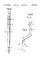
- FIG. 1is a cross-sectional view taken through the midline of a patient who has lost support of the periurethral tissue at the UVJ, and is thereby suffering from stress urinary incontinence;
- FIG. 2is the same view as FIG. 1, however the structural defect has been corrected using the method and apparatus of the present invention
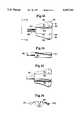
- FIG. 3is a top plan view of a bone anchor used in the method of the present invention.
- FIG. 4is a side plan view of the bone anchor of FIG. 3;
- FIG. 5is a top plan view of a drill tamper tool of the present invention wherein a portion of the tool has been broken-away;
- FIG. 6is a side plan view of the tamper tool of FIG. 5;
- FIG. 7is an end plan view of the tamper tool of FIG. 5, taken along line 7--7 thereof;
- FIG. 8is a top plan view of a bone anchor insertion tool of the present invention, wherein a portion of the tool has been broken-away;
- FIG. 9is a side plan view of the insertion tool of FIG. 8;
- FIG. 10is a side plan view of the insertion tool of FIG. 8 with the bone anchor of FIG. 3 loaded thereon;
- FIG. 11is a side plan view of a suture retriever of the present invention.
- FIG. 12is an end plan view of the suture retriever of FIG. 11, taken along the line 12--12 thereof;
- FIG. 13is a top plan view of a suture template of the present invention.
- FIG. 14is a side plan view of the template of FIG. 13;
- FIG. 15is a bottom plan view of the template of FIG. 13;
- FIG. 16is an end plan view of the template of FIG. 13, taken along line 16--16 thereof;
- FIG. 17is a perspective view of the template of FIG. 13 in use during a surgical procedure with portions of the patient's anatomy cut-away for clarity;
- FIG. 18is a perspective view of an alternative embodiment of the suture template according to the present invention.
- FIG. 19is a perspective view of the insertion tool of FIG. 8 in use during a surgical procedure with portions of the patient's anatomy cut-away for clarity;
- FIG. 20is a perspective view of the surgical procedure of the present invention wherein portions of the patient's anatomy cut-away for clarity, and wherein the suture retriever of FIG. 11 is being employed;
- FIG. 21is a perspective view of the surgical procedure of the present invention wherein portions of the patient's anatomy cut-away for clarity, and wherein the sutures have been retrieved from the pre-peritoneal region for tying;
- FIG. 22is a perspective view of the space of Retzius, and illustrates the proper placement of the anchors and sutures employed in the present invention.
- a surgical method for performing laparoscopic urethropexy on a patientcomprises the steps of:
- the sutureis secured to the periurethral tissue by pulling said suture through the periurethral fascia and vaginal mucosa into the vagina, and tying said suture within the vagina. More preferably, a pair of bores are created in the pubic bone, with one of said bores on either side of the pubic symphysis above the periurethral fascia. A pair of anchors are then provided, each of said anchors having a suture extending therefrom, and one of said pair of anchors is inserted into each of said bores (i.e., each bore has an anchor inserted therein).
- One of said suturesis pulled through the periurethral fascia and vaginal mucosa adjacent either side of the urethra into the vagina, and each of said sutures is then tied within the vagina, such that one of said sutures will provide an upward force on the periurethral tissue positioned on either side of the urethra, thereby elevating the urethra to the desired angle.
- the periurethral tissuepreferably both the periurethral fascia and vaginal mucosa
- the bore creation steppreferably comprises:
- the distal end of said boring tipis preferably sufficiently sharp to enable said tip to create said bore in the cancellous bone by means of hand force, while being insufficiently sharp to inadvertently pierce soft tissue or organs during the bore creation step.
- the drill tamper toolpreferably comprises an elongate rigid member having:
- said boring tipbeing of conical cross section, and having flat sides which taper from said distal end of the boring tip to a cylindrical rear portion of said boring tip, said rear portion having a diameter which corresponds to the diameter of the bore created in the pubic bone;
- said boreis created by inserting said distal end of the boring tip into said crater, and rotatingly urging said boring tip into said crater by means of said handle.
- the collaracts as a stop during said bore creation step such that the length of said bore is approximately equivalent to the length of said boring tip. While the collar may comprise a conically-shaped portion positioned between the rear portion of the boring tip and the intermediate portion, the collar may also simply comprise the end of said intermediate portion positioned adjacent the cylindrical rear portion of said boring tip.
- the dissecting steppreferably comprises:
- the anchor insertion steppreferably comprises:
- anchor-insertion toolcomprising a rigid, elongate member having:
- the anchor-insertion toolpreferably further comprises an elastic band extending about its circumference.
- the anchor loading stepfurther comprises positioning said suture between said elastic band and said anchor-insertion tool so that said suture is securely held against said insertion tool by said elastic band.
- said sutureis permitted to slide between said elastic band and said insertion tool so that said suture is tensioned between said anchor and said insertion tool to thereby pull outwardly on said anchor in order to seat the anchor within said bore.
- the step of pulling said insertion tool away from said boremay also comprise removing said insertion tool at least partially from the laparoscopic channel, so that after said pulling step said suture is tensioned between said anchor and said insertion tool.
- the suture securing stepmay then comprise:
- the suturehas first and second tails, and the tails are pulled into the vagina in this fashion a predetermined distance from each other.
- the two tailsare then tied to each other within the vagina in order to elevate the urethra to the desired angle.
- the anchor-insertion toolalso preferably further comprises a shouldered depression extending about the circumference of said anchor-insertion tool, wherein said elastic band is positioned within said depression during said anchor loading step.
- the insertion toolmay comprise a cylindrical intermediate portion having a distal end adjacent said anchor-receiving tip, said intermediate portion having a diameter greater than the diameter of said anchor-receiving tip.
- the diameter of said anchor-receiving tipis approximately equivalent to the diameter of said anchor; and the combined length of said anchor and said anchor-receiving tip is approximately equivalent to the depth of said bore.
- the present inventionalso provides a drill tamper tool for laparoscopically creating a bore in the pubic bone of a patient during a urethropexy procedure, said tool comprising an elongate, rigid member having:
- said toolmay be employed laparoscopically to create a bore in the pubic bone by inserting said distal end of the boring tip into a crater previously created in said pubic bone, said crater being sufficiently deep to provide access to the cancellous bone, and rotatingly urging said boring tip into said crater by means of said handle in order to create said bore, said bore having a length corresponding to the length of said boring tip.
- the boring tip of the drill tamper toolpreferably has a conical cross section, and flat sides which taper from said distal end of the boring tip to a cylindrical rear portion of the boring tip, wherein the tool may be employed to create a bore having a diameter which corresponds to the diameter of said rear portion.
- the total length of said drill tamper toolis such that said tool may be readily employed through a laparoscope in order to create a bore in the pubic bone of a patient during a laparoscopic urethropexy procedure.
- the boring tiphas a length of between about 1 and about 3 centimeters
- the intermediate portionhas a length of between about 2 and about 6 centimeters
- the guide portionhas a length of between about 50 and about 55 centimeters.
- the present inventionalso provides an anchor-insertion tool for laparoscopically inserting and securing an anchor within a bore created in the pubic bone of a patient during a urethropexy procedure, said anchor having at least one suture extending therefrom, said anchor-insertion tool comprising an elongate, rigid member having:
- the anchor-insertion toolpreferably further comprises at least one shouldered depression extending about the circumference of said tool, said depression sized so as to accommodate an elastic band for holding said suture between said elastic band and said tool.
- a pair of tapered grooves extending along opposite sides of said tip and at least partially along the length of said intermediate portionare also preferably provided.
- a second shouldered depression extending about the circumference of said toolmay also be provided, said second depression sized so as to accommodate an elastic band for holding said suture between said elastic band and said tool, wherein both of said shouldered depressions extend about said cylindrical guide portion.
- the anchor-receiving tiphas a pair of guide tabs extending from either side of the end of said tip opposite said intermediate portion, said guide tabs matingly receivable in corresponding grooves on an anchor to thereby hold an anchor on said anchor-receiving tip.
- the total length of said anchor-insertion toolis such that said tool may be readily employed through a laparoscope in order to insert an anchor in the pubic bone of a patient during a laparoscopic urethropexy procedure.
- the intermediate portionmay have a length between about 2 and about 6 centimeters
- the guide portionmay have a length between about 50 and about 55 centimeters.
- the present inventionalso provides a loaded anchor-insertion tool (i.e., the anchor-insertion tool having an anchor loaded thereon).
- the anchormay comprise:
- the anchor-insertion toolpreferably has:
- the guide tabsare matingly received in said grooves on said anchor to thereby hold the anchor on said anchor-receiving tip, wherein said suture extends through said aperture on said anchor, and wherein said suture is positioned within said pair of tapered grooves on said anchor-insertion tool.
- a surgical kit for laparoscopically inserting an anchor into the pubic bone of a patient during an urethropexy procedureis provided.
- This kitpreferably comprises the drill tamper tool and the anchor-insertion tool described above.
- FIG. 1is a cross-sectional view taken along the midline of a patient suffering from stress urinary incontinence.
- FIG. 1depicts bladder 1, urethra 2, urethrovesicular junction (UVJ) 3, periurethral tissue 4, vagina 5, uterus 6, pubic symphysis 7, and space of Retzius 8.
- urethra 2 and the associated periurethral tissue 4have sagged into vagina 5.
- pressurewill be exerted on bladder 1.
- urethra 2Due to the collapse of urethra 2, the surrounding musculature will be unable to provide sufficient counteractive pressure on urethra 2 to prevent loss of urine during these periods of stress.
- fixation of periurethral tissue 4 at UVJ 3 on either side of urethra 2will act to support the urethra and prevent the sagging of urethra 2 into vagina 5. This in turn will enable the surrounding musculature to provide sufficient pressure on urethra 2 to prevent loss of urine during moments of stress.
- FIG. 2depicts the resulting support of urethra 2 at UVJ 3 by means of the surgical procedure of the present invention.
- pubic bone 12is shown in FIG. 2, and is that portion of the pubic bone lying immediately to the right of the pubic symphysis.
- the anchors of the present inventionare secured in the pubic bone on either side of the pubic symphysis.
- a bore 13has been produced in pubic bone 12, and anchor 9 has been secured within bore 13. It should be noted that bore 13 and anchor 9 have been enlarged for purposes of clarity.
- a suture 10is secured to anchor 9, and the two tails of suture 10 extend downwardly through the space of Retzius 8 into vagina 5.
- the tails of suture 10extend into the vagina immediately to the right of urethra 2 through periurethral tissue 4 at UVJ 3.
- the two tails of suture 10are tied to one another such that suture 10 provides an upward force on periurethral tissue 4 on the right side of urethra 2 adjacent UVJ 3.
- An identical anchor and suture combinationis secured to the pubic bone on the left side of the pubic symphysis, and the suture enters the vagina in a similar fashion as before in order to provide an upper force on periurethral tissue 4 on the left side of urethra 2. In this fashion, the sutures on either side of the urethra act to restore the angle of the urethra at the UVJ.
- the securing of the anchors to pubic bone 12can be accomplished laparoscopically.
- Suture 10may then be pulled into vagina 5 through periurethral tissue 4 immediately adjacent to urethra 2.
- the two tails of suture 10may then be tied to one another within vagina 5 by hand. It has been found that the portion of suture 10 positioned within vagina 5 will be epithelialized within a few days after the procedure. In this fashion, suture 10 will not cause any discomfort or irritation to the patient since suture 10 will quickly be covered by the epithelium of vagina 5.
- Identification of patients suitable for the techniques of the present inventionmay be made by any of the known techniques for identifying patients amenable to SUI correction by MMK or similar procedures. For example, as discussed previously a cotton swab may be inserted into the urethra until the end of the swab reaches the UVJ. The patient is then asked to bear down and the movement of the portion of the swab outside of the urethra is monitored. The external urethral meatus will act as a fulcrum for the cotton swab, and a loss of urethral support at the UVJ can be readily identified by the upward movement of the external end of the cotton swab. This indicates a downward descent of the urethra at the UVJ, which in turn provides an indication of the structural cause of the patient's SUI. Other means known in the art, however may be employed to confirm the diagnosis and/or to rule out other possible causes.
- the preoperative preparation of the patientfollows standard procedures for laparoscopic and gynecological surgeries, however no enema is needed.
- the patientis placed in the dorsal lithotomy position, and standard parenteral antibiotics are applied.
- the patientis also placed under general anesthesia in order to minimize discomfort.
- a Foley catheter(16 French with 10 cc balloon) is then inserted into the urethra.
- the balloon of the Foley catheteris inflated, and the catheter is gently pulled outwardly to ensure proper placement of the balloon at the juncture of the bladder and the urethra.
- Proper placement of Foley catheter 14is shown in FIG. 17 wherein a portion of vagina 5 has been cut-away for purposes of clarity.
- Bladder 1is thereafter drained in the usual fashion using the Foley so that the bladder will become deflated.
- maintaining the bladder in a deflated stategreatly simplifies the procedure of the present invention.
- Foley catheter 14be positioned in the manner shown in FIG. 17 for reasons which will be described further herein.
- urethra 2may be readily measured by means of any suitable apparatus which may be inserted into the urethra, as long as the surgeon can be certain that one end of the device is positioned at the juncture of the bladder and the urethra (i.e., the UVJ).
- the simplest means of obtaining this measurementis to provide graduations along at least a portion of the length of Foley catheter 14, as shown in FIG. 17.
- the length of the urethracan be determined using the graduations which will be readily visible immediately adjacent the end of urethra 2. While the average urethra is 3 cm in length, this can often vary between about 2.7 and about 3.3 cm.
- the suture template employed in the method of the present inventioncan thus be manufactured in different sizes to accommodate the differing urethra lengths. A minimum of two sizes for the template may be provided, and more preferably at least three different sizes. Alternatively, the graduations may be employed to facilitate proper placement of a single-sized template.
- Balloon dissectioncan be accomplished using the SPACEMAKER surgical balloon dissector manufactured by General Surgical Innovations of Portola Valley, Calif., or an equivalent device.
- This devicehas a guide rod to which a small balloon is attached.
- the guide rodis inserted into the infraumbilical incision until the tip of the rod reaches the pubic symphysis in the space of Retzius (i.e., between the symphysis and the bladder).
- the balloonis then inflated in space of Retzius 8 by filling the balloon with approximately 300 cc of saline solution or other suitable fluid, thereby further deflating bladder 1 and separating the surrounding connective tissue in order to provide sufficient room in space of Retzius 8 for the fixation procedure of the present invention.
- the balloonis then aspirated and removed from the pre-peritoneal region.
- the SPACEMAKER devicehas an integral trocar which may normally be left in the infraumbilical incision for placement of the laparoscope, the only size currently available is too small for the procedure of the present invention. Obviously a properly sized integral trocar could remain in the patient after removal of the deflated balloon.
- the SPACEMAKER deviceis removed in its entirety, and a larger 12 mm trocar is inserted into the infraumbilical incision.
- a 12 mm WOLF operating/laser laparoscopepreferably with a WOLF 50/50 beamsplitter camera
- the pre-peritoneal regionis then insufflated, preferably with CO 2 at a pressure between about 10 and about 30 mm Hg, thereby further expanding the space of Retzius and providing excellent laparoscopic vision in this region.
- the procedure of the present inventionmay be employed with any of a variety of bone anchors, provided that the anchor can be readily secured to the pubic bone and a suture can be attached thereto. It is presently preferred, however, that the MITEK bone anchors known to those skilled in the art be employed for this purpose. As discussed more fully herein, these anchors are secured in place by pressing them into properly-sized bores created in the pubic bone.
- the MITEK-MMK and related proceduresrequire the use of either a mechanical drill or hand-operated awl in order to provide the bore for insertion of a bone anchor (such as those manufactured by Mitek Surgical Products, Inc.) into the pubic bone. While these devices may be readily employed with large abdominal incisions, they cannot be used through a laparoscope for a number of reasons. Most importantly, these tools must be sufficiently sharp to enable the surgeon to penetrate the hard outer layers of the pubic bone (periosteum and cortical bone). Since the field of vision through a laparoscope may be limited at times, however, it is very risky to employ such sharp implements as there is a tremendous risk of puncturing the bladder or other soft tissue in the operative area.
- a bone anchorsuch as those manufactured by Mitek Surgical Products, Inc.
- pubic bone 12falls away from the laparoscope at an angle of approximately 45°.
- the angularity of pubic bone 12therefore provides vision and operative difficulties which are overcome by the apparatus and methods of the present invention.
- Simply drilling into pubic bone 12 using prior art apparatus through the laparoscopeis not advisable because the drill or awl tip will tend to slide downwardly during the drilling operation because of the manner in which pubic bone 12 angles downwardly away from the laparoscope. While the drill tip may eventually penetrate the hard outer periosteum of the bone, the drill may enter at an improper location or angle due to downward slippage of the drill tip.
- a bore in pubic bone 12which is at an angle of approximately 45-degrees to the surface of the bone into which the bore is produced. This angle may, however, be between about 20 and about 60-degrees, to thereby provide sufficient support for the bone anchor to be placed in the bore thus produced.
- Applicanthas developed a novel method and apparatus for creating the required bores in the pubic bone through a laparoscope.
- the method and apparatusavoid the use of any sharp tips, while still enabling the surgeon to properly place the bores in the pubic bone without a risk of misalignment during the bore creation process.
- a laseris first employed to produce a cone-shaped crater in the pubic bone at the desired bore location.
- the crateris produced in the periosteum and cortical bone, thereby providing access to the soft cancellous, or tribecular, bone.
- a drill tamper tool(to be described further herein) may then be employed to create the properly-sized bore.
- a CO 2 laser(such as a SHARPLAN 20 watt) is inserted through the laparoscopic channel, and is employed to create a cone-shaped crater slightly larger than the diameter of the laser beam in the pubic bone on either side of the pubic symphysis.
- the diameter of the laser beamis preferably about 2 mm, and therefore the cone-shaped crater created in the pubic bone is slightly larger than 2 mm in diameter.
- the cratershould be sufficiently deep to reach the cancellous bone.
- a crateris established on either side of the pubic symphysis directly above and approximately 1 cm lateral to the periurethral fascia at the UVJ.
- the bore for insertion of the anchormay be readily created using the drill tamper tool of the present invention. Since the cancellous bone is significantly softer than the periosteum or cortical bone, it is not necessary that a sharp awl or drill bit be used to create the bore. Rather, a bluntly pointed drill tamper tool may be used, wherein the end of the tamper tool is not sufficiently sharp to puncture the bladder or other soft tissue under normal use.
- the drill tamper tool of the present inventionis shown in FIGS. 5-7, and comprises an elongate rigid member 20 having a distal end which comprises a conical boring tip 21.
- End 22 of conical boring tip 21preferably has a cross section similar in size and shape to the crater created in the pubic bone by the laser. In this fashion, alignment of conical boring tip 21 within the crater will be relatively easy. It is also preferred that end 22 of conical boring tip 21 be blunt so that it will not penetrate soft tissue such as the bladder during normal use (i.e., not sufficiently sharp to penetrate soft tissue or organs during normal use).
- conical boring tip 21should be sufficiently thin and blade-like to permit boring tip 21 to create the bore in the soft cancellous bone by use of hand force through the laparoscope.
- conical boring tip 21is preferably shaped similar to a flat bladed screwdriver.
- boring tip 21has tapered side surfaces 23 and 24 which terminate in portion 25 which is of a circular cross-section.
- the diameter of circular-cross-section portion 25is identical to the diameter of the bore which will be created in the pubic bone. By rotating the drill tamper tool while simultaneously pressing boring tip 21 into the crater in the pubic bone, the desired bore will be readily created therein.
- the diameter of portion 25is also approximately the same as the body of the anchor to be inserted into the bore.
- collar 26is provided on the drill tamper tool. Collar 26 is of a larger diameter than conical boring tip 21, and therefore will act as a stop preventing further penetration of the drill tamper tool into the bone. Although collar 26 is shown as tapering in diameter between conical boring tip 21 and intermediate portion 27, it is also possible that collar 26 simply comprise a non-tapered end of intermediate portion 27. Intermediate portion 27 has a diameter significantly greater than that of conical boring tip 21, and is positioned on the opposite end of collar 26. Intermediate portion 27 not only allows the provision of collar 26, but also adds rigidity to the tamper tool.
- Intermediate portion 27should be significantly smaller in diameter than the operative channel of the laparoscope so that sufficient vision of the operative region is provided.
- the length of conical boring tip 21is between about 1, and 3 cm, and most preferably about 1.4 cm.
- Intermediate portion 27is preferably between about 2, and 6 cm, and most preferably about 5 cm.
- cylindrical guide portion 28is also included on the drill tamper tool.
- Guide portion 28has first end 29 and second end 30.
- First end 29is attached to intermediate portion 27 at the opposite end of collar 26.
- Cylindrical guide portion 28preferably has a diameter slightly less than the operative channel of the laparoscope. In this fashion, guide portion 28 provides the necessary stability within the laparoscope to ensure proper placement of the bores.
- Second end 30 of guide portion 28is preferably attached to handle 31. While handle 31 is shown as having a flat end portion 32 and curved hand grip surfaces 33, handle 31 can be of a variety of forms and still be sufficient for purposes of the present invention.
- Handle 31facilitates the proper manipulation of conical boring tip 21 through the laparoscope, and provides a sufficiently firm surface 32 upon which force may be applied to complete the boring operation.
- Guide portion 28preferably has a length between about 50 and about 55 cm, and most preferably about 52 cm.
- the overall length of the drill tamper tool of the present invention thereforpermits sufficient access to the pubic bone, while also providing an ergonomically-effective boring operation through the laparoscope and ensuring that the tool does not interfere with the anesthesiologist.
- Anchor 9which is preferably made of titanium alloy or other suitable material, has a cylindrical body 40 and a conical end 44 attached thereto. At least two flexible barbs 41 curve outwardly away from body 40.
- a groove 42is provided on either side of body 40 at the end opposite to conical end 44.
- cylindrical end 45extends away from body 40 adjacent groove 42. The longitudinal axis of cylindrical end 45 is aligned with the longitudinal axis of body 40.
- the diameter of cylindrical end 45is preferably equivalent to the diameter of body 40 within grooves 42 positioned on opposite sides of body 40. As will be understood below, this structure facilitates the attachment of anchor 9 to an insertion tool.
- body 40 and cylindrical end 45have an aperture 43 provided therethrough.
- Aperture 43is sized so as to accommodate a suture appropriate for the fixation procedure of the present invention. It is preferred that a size 0 GORE-TEX suture be employed, and thus anchor 9 and its accompanying aperture 43 should be sized accordingly. The use of a GORE-TEX suture is preferred for reasons of strength and non-elasticity. Certainly other types of sutures could be employed if necessary. A portion of suture 10 is shown in FIG. 3 having been inserted through aperture 43.
- anchor 9is relatively straightforward, and merely requires that the anchor be pressed completely into the bore which has previously been created in the pubic bone.
- anchor 9is inserted into the bore in the pubic bone until conical end 44 reaches the distal end of the bore.
- the boreshould be at least as long as the length of anchor 9, however, it is preferably considerably longer to ensure sufficient support for the anchor.
- flexible barbs 41will be compressed against body 40 as they are inserted past the hard periosteum and cortical bone surrounding the bore. Once within the bore, however, flexible barbs 41 will tend to spring back into the soft cancellous bone, thereby securing the anchor in place. A slight tug on the tails of the suture 10 will also cause barbs 41 to further deploy.
- the anchor insertion tool shown in FIGS. 8-10may be employed.
- the anchor insertion tool of the present inventionhaving an anchor and threaded suture loaded thereupon, is inserted into the laparoscope for proper seating of anchor 9.
- the anchor insertion tool of the present inventioncomprises a rigid elongate member 50 having a handle 51 at one end, and an anchor-receiving tip 52 at the opposite end of elongate member 50.
- handle 51can be of any variety, and that shown is only the presently-preferred embodiment of this handle.
- Anchor-receiving tip 52is similar in construction to that shown in FIGS. 4-6 of U.S. Pat. No. 5,207,679.
- Anchor-receiving tip 52is constructed so as to matingly receive anchor 9 in order to facilitate insertion of anchor 9 into the bore.
- the longitudinal axis of anchor-receiving tip 52should be aligned with the longitudinal axis of elongate member 50.
- Anchor-receiving tip 52is cylindrical in nature, having a diameter approximately equivalent to body 40 of anchor 9. In this manner, at least a portion of anchor-receiving tip 52 may pass through the bore in the pubic bone during the anchor insertion process to properly seat the anchor completely within the bore.
- Anchor-receiving tip 52has a pair of guide tabs 53 extending from the end of anchor-receiving tip 52 on either side thereof.
- Guide tabs 53are sized and shaped so as to be matingly received within grooves 42 positioned on either side of anchor 9.
- Anchor-receiving tip 52also has a cylindrical slot 54 aligned with the longitudinal axis of tip 52. Cylindrical slot 54 should correspond in size and shape to cylindrical end 45 of anchor 9 in order to matingly receive the same. It is also preferable that the distance between guide tabs 53 be slightly smaller than the distance between the corresponding grooves 42 on anchor 9. In this fashion, guide tabs 53 as well as cylindrical slot 54 will apply compressive force against anchor 9 thereby more securely holding anchor 9 in place when loaded within anchor-receiving tip 52.
- a pair of tapered grooves 55are provided on either side of the anchor insertion tool, and extend from the end of anchor-receiving tip 52 along at least a portion of the length of elongate member 50. As best shown in FIG. 10 wherein anchor 9 has been loaded upon the insertion tool, grooves 55 ensure that the sutures will be protected by anchor-receiving tip 52 and a portion of elongate member 50 during the insertion process. Since any nicks in the suture may compromise the strength and permanency of the fixation, it is important to ensure that the suture is not damaged in any fashion.
- Anchor-receiving tip 52should also be of the proper length to ensure deep placement of anchor 9 completely within the bore.
- the length of the combination of anchor-receiving tip 52 and bone anchor 9 when loaded in the manner shown in FIG. 10should be equivalent to the size of the bore created in the pubic bone. Since the diameter of elongate member 50 is significantly greater than that of anchor-receiving tip 52, distal end 56 of elongate member 50 will firmly abut the pubic bone once the anchor has been completely inserted into the bore. In this manner, the surgeon can be certain that the anchor has been seated to its complete and proper depth.
- elongate member 50further comprises an intermediate section 57 and a guide portion 58.
- Intermediate portion 57should have a diameter sufficiently less than that of the laparoscope in order to provide adequate vision for the surgeon, and intermediate portion 57 also has distal end 56 described above.
- intermediate portion 57has a length between about 2 and about 6 cm, most preferably about 5 cm. It should be kept in mind that, as shown in FIG. 10, suture 10 will extend along the length of intermediate portion 57 on either side thereof. This consideration must be kept in mind when sizing the diameter of intermediate portion 57 to ensure not only that it can be easily inserted through the laparoscope, but also to ensure adequate vision.
- Guide portion 58will necessarily be slightly smaller than the diameter of the guide portion for the drill tamper tool previously described, since, as shown in FIG. 10, suture 10 will extend along either side of guide portion 58.
- the total of the diameter of guide portion 58 and twice the diameter of suture 10should be only slightly less than the inside diameter of the operative channel of the laparoscope.
- guide portion 28provides a rigid support for the surgeon during the anchor insertion process.
- guide portion 58has a length between about 50 and 55 cm., most preferably about 52 cm. This provides an overall inserter length comparable to that of the drill tamper tool, thereby providing the same advantages with regard to the tamper tool length.
- first and second shouldered depressions 59 and 60are preferably provided about the circumference of guide portion 58.
- a small rubber band 61(as shown in FIG.
- First shouldered depression 59is preferably positioned approximately 10 cm from the ends of guide tabs 53.
- Second shouldered depression 60is preferably positioned about 40 cm from guide tabs 53. Both shouldered depressions act, in conjunction with an elastic band contained therein, to hold suture 10 in place on the sides of the anchor insertion tool.
- the shouldered depression/elastic band combinationfurther improves the laparoscopic procedure of the invention by not only assisting in seating the anchor, but also in the suture retrieval process.
- the anchor insertion tool of the present inventionwith a pre-loaded anchor and suture assembly attached thereto, is inserted through the laparoscope for placement of the anchor as previously described. Once the anchor has been seated within the bore, the anchor insertion tool is then pulled outwardly utilizing handle 51 contained thereon.
- the combination of shouldered depressions 59 and 60 and rubberband 61act to provide tension in suture 10 which in turn pulls outwardly on anchor 9 which is now contained in the bore.
- the drill tamper tool and the anchor-insertion tool described abovemay be provided in the form of a reusable surgical kit.
- FIG. 20is a perspective view of the procedure with portions of the patient's anatomy cut-away for purposes of clarity.
- first shouldered depression 59 in combination with rubberband 61will cause both suture tails to be tensioned between the anchor and the anchor insertion tool as shown.
- the suture tailswould merely fall into the space of Retzius similar to a ball of yarn, and thereby be difficult (if not impossible) to retrieve.
- a suture retrieving toolmay be inserted into the vagina and then pressed upwardly on one side of the urethra into the space of Retzius in order to retrieve one of the suture tails in the manner shown.
- the suture retrieving toolmust have a sharp point capable of passing completely through the full thickness of the periurethral fascia and vaginal mucosa adjacent the urethra.
- the suture retrieval toolmust also have a means for grasping the suture tail and pulling the tail back through the full thickness of the periurethral and vaginal mucosa by means of the same entry hole created by the sharp point.
- each tailis pulled into the vagina in this fashion at the proper location.
- one tailis pulled into the vagina approximately 1 cm from the urethra at the UVJ, and the other tail is pulled into the vagina approximately 2 cm lateral from the urethra.
- each tailpenetrates the periurethral tissue along an imaginary line extending substantially perpendicularly away from the urethra.
- Each tailmay then be pulled out of the vagina for purposes of tying.
- the suture tailsare tied to one another using a series of standard surgeon's knots, and each knot is slid by hand to the point in the vagina at which the suture tails were previously retrieved.
- the tailsare tied to one another in a sufficiently tight fashion so that suture 10 creates an upward force on the periurethral tissue adjacent the urethra in order to elevate the urethra at the UVJ and restore the urethra to its proper angle.
- the position of the urethracan be readily observed by the surgeon as this procedure is performed, thereby ensuring that the urethra is restored to the desired angle.
- anchor insertionanchor insertion, suture retrieval, etc.
- suture retrievaletc.
- the entire procedureis then repeated for the anchor placed on the opposite side of the pubic symphysis, and the suture tails of that anchor are pulled into the vagina through the periurethral tissue on the opposite side of the urethra as the first suture tails.
- Tyingis then performed in the same fashion, thereby elevating the other side of the urethra to thereby completely restore the urethral angle at the UVJ.
- FIG. 2wherein it is shown that suture 10, and the corresponding suture on the opposite side of the urethra have restored the urethra to its proper angle. It should be noted that at no time do the sutures pull upward directly beneath the urethra, since doing so would create the risk that the suture would cause urethral blockage. After tying, the remaining tails of suture 10 are cut at the knot. The portion of suture 10 remaining in the vagina will epithelize within three to four days, and the patient will no longer sense that the sutures are in place.
- the resultis a permanent fixation of the periurethral tissue on both sides of the urethra, thereby restoring the urethra to its correct angle and eliminating the SUI.
- the surgical area within the patientis flushed with a dilute lidocaine solution, the laparoscope and trocars removed, a stronger lidocaine solution is applied to the incision sites, and the incisions are closed in the usual fashion.
- the Foley cathetermay then be removed, and the patient permitted to recover in the usual fashion. Normal everyday activities may be resumed within 2-3 days.
- a U.S. Surgical Auto-Stitch toolmay be effectively employed for this purpose. It is critical, however, that the tool employed being capable of readily be inserted through the periurethral tissue from the vagina into the space of Retzius, while also being capable of grasping the suture tails. It is also critical that the surfaces contacting suture 10 be perfectly smooth in order to eliminate the risk of nicks or cuts in suture 10 which would obviously compromise the effectiveness of the procedure. Applicant has developed a novel suture retriever for accomplishing this purpose which provides a convenient and simple means of retrieving the suture tails.
- the suture retrieval tool of the present inventionis depicted in FIG. 11, and comprises metal retrieving end 65, midshaft 66, and handle 67.
- Midshaft 66 and handle 67may be singularly molded from polycarbonate or a similar FDA-approved material in the typical fashion.
- handle 67is also preferably knurled in order to facilitate grasping and manipulation of the retriever.
- Metal retrieving end 65is preferably made of stainless steel and can be securely molded into distal end 68 of midshaft 66.
- Metal retrieving end 65comprises a rigid, rod-like shaft 69, and a sharp tip 70 capable of penetrating the periurethral tissue.
- the diameter of distal end 68is preferably significantly greater than that of shaft 69, and will act as a stop in order to limit the penetration of the suture retrieval tool into the space of Retzius.
- the length of shaft 69 and tip 70may be selected so as to ensure that when the suture retrieval tool is inserted into the space of Retzius through the vagina that sharp tip 70 will generally be incapable of striking any surrounding soft tissue.
- Retrieving end 65further comprises a return leg 71 which extends away from sharp tip 70 in the same direction of shaft 69.
- Shaft 69, return leg 71 and the underside of sharp tip 70thus create an inverted U-shaped region capable of ensnaring suture 10 for retrieval purposes.
- the distance between return leg 71 and shaft 69 in the region of the inverted U-shapeis preferably approximately the same diameter as suture 10. In this fashion, and as shown in FIG. 20, after sharp tip 70 has penetrated the periurethral tissue adjacent the vagina in order to enter the space of Retzius, the inverted U-shape may be pulled downwardly over a suture tail, thereby snaring the suture.
- Metal retrieving end 65may then be pulled back through the periurethral tissue, and the tail of suture 10 will remain snared between return leg 71 and shaft 69 directly beneath sharp tip 70. Although the suture tail will slide within the U-shaped region, it will nevertheless be pulled into the vagina.
- metal retrieving end 65which contact suture 10 must be rounded and smooth in order to permit suture 10 to freely slide within the inverted U-shaped portion as the retriever is withdrawn. This prevents nicking or fraying of the suture while still permitting the suture tail to be withdrawn.
- the only sharp portion of metal retrieving end 65is sharp tip 70.
- handle 67, midshaft 66, and metal retrieving end 65may all be positioned along the same longitudinal axis thereby forming a rigid, elongate structure
- metal retrieving end 65preferably is positioned at an angle of between about 50 degrees and about 80 degrees, most preferably about 60 degrees, to midshaft 66 (this angle is indicated as A in FIG. 11).
- handle 67is preferably positioned at an angle of between about 50 degrees and about 80 degrees, most preferably about 60 degrees, to handle 67 (this angle is indicated as B in FIG. 11).
- the longitudinal axis of shaft 69 of metal retrieving end 65will be parallel to the longitudinal axis of handle 67.
- midshaft 66will generally be positioned parallel to the longitudinal axis of the vagina.
- Metal retrieving end 65will then extend upwardly through the periurethral tissue into the space of Retzius as desired.
- handle 67will thereby extend downwardly outside of the vagina, and thus sharp tip 70 may be readily forced through the periurethral tissue as desired merely by pushing upwardly on handle 67.
- the transitions between handle 67 and midshaft 66 as well as between midshaft 66, and retrieving end 65should be gently curved in order to ease placement. It should be noted that angles A and B can vary significantly, however it is preferred that they be as close to one another as possible so that the parallel relationship of handle 67 and retrieving end 65 is maintained. In addition, the present configuration ensures that the retrieving end 65 will enter the space of Retzius at an angle of approximately 90 degrees to the tensioned suture tails (i.e., the suture tails tensioned between the anchor and the anchor insertion tool). This perpendicular relationship allows for effective snaring of the suture, as well as improved vision of the retrieval through the laparoscope.
- midshaft 66is between about 2 and about 6 cm. in length, most preferably about 4 cm.
- the cross-sectional area of midshaft 66should merely be a size chosen to provide the necessary rigidity while also not blocking vision within the vagina during the procedure.
- handle 67is preferably about 4 cm long, however the length is not as critical since handle 67 remains completely outside of the body.
- the diameter of handle 67should be chosen so as to provide a comfortable and secure means of grasping the suture retrieval tool.
- handle 67is about 3 cm in diameter.
- a templatewherein the template has at least two apertures which may be properly positioned on either side of the urethra.
- the suture retrievermay then be inserted through these apertures and thereafter through the periurethral tissue in order to snare the suture tails in the manner described previously.
- the presently preferred templateis depicted in FIGS. 13-17.
- the templatecomprises a trough 80 of arcuate cross-section, wherein trough 80 is sized so as to cradle the patient's urethra when properly positioned.
- First and second wing members 81 and 82extend away from opposite sides of trough 80, preferably perpendicularly to the longitudinally axis of trough 80 in the manner shown. Most preferably wing members 81 and 82 extend perpendicularly away from opposite sides of trough 80 at the upper most edges 83 and 84 of trough 80.
- First and second suture guide apertures 85 and 86are positioned in each of the wing members 81 and 82 as shown.
- the guide aperturesare positioned so that when the urethra of the patient is properly positioned within trough 80, guide apertures 85 and 86 on each wing will indicate the proper location for the sutures.
- First suture guide aperture 85is positioned so that the first tail of suture 10 will penetrate the periurethral tissue approximately 1 cm from the urethra adjacent the UVJ.
- Second guide aperture 86is preferably positioned about 1 cm further away from the urethra along a line perpendicular to the longitudinal axis of trough 80. In other words, the distance between first suture guide aperture 85 and second suture guide aperture 86 is preferably about 1 cm. In this manner, the surgeon can be confident that sufficient periurethral tissue will be present between the two suture tails.
- the template of the present inventionmay merely be held in place by hand, and in fact the downwardly sloping nature of the underside wing members 81 and 82 are suitable for placement of the surgeon's fingers thereunder. Additional alignment means are preferably provided, however at a minimum, end wall 87 is provided at the end of trough 80 furthest away from the suture guide apertures.
- end wall 87is provided at the end of trough 80 furthest away from the suture guide apertures.
- the distance between end wall 87 and first and second guide apertures 85 and 86should be between about 2.5 and about 3.2 cm, most preferably about 2.8 cm.
- the guide aperturesshould also be between about 0.25 and about 0.5 cm from distal end 91 of the wing members (FIG. 13).
- Alignment member 88is preferably positioned parallel to trough 80, with the center line of alignment member 88 aligned with the center line of trough 80. Alignment member 88 may either extend away from trough 80 as shown in FIG. 13, or alternatively may extend away from end wall 87 directly along the interior of trough 80 as shown in FIG. 18.
- alignment member 88is preferably sized so that when the template is manufactured from a resilient material, alignment member 88 may be rigidly snapped about Foley catheter 14 as shown in FIG. 20.
- the shaft of Foley catheterwill be securely held within alignment member 88, and the surgeon need only pull outwardly on the Foley catheter while sliding the template into the vagina towards the urethra until end wall 87 abuts end 89 of urethra 2.
- the ball of the Foley catheterwill thus be positioned at the UVJ, and the template will likewise be positioned at the appropriate location assuming that a template of the proper size has been selected based upon the length of the urethra.
- a single, larger-sized templatemay be employed provided that alignment member 88 is snapped about the shaft of Foley catheter 14 in the proper location.
- end wall 87is instead aligned with the appropriate graduation along the shaft of Foley catheter 14 based upon the previously-measured length of the urethra.
- end 90 of alignment member 88could alternatively be aligned with the appropriate graduation along the shaft of Foley catheter 14 in order to provide the proper placement of the template based upon the length of the patient's urethra.
- FIG. 18depicts yet another alternative embodiment for the template of the present invention in which alignment member 88 extends along the interior of trough 80.
- alignment member 88is inserted into the urethra along with Foley catheter 13 until end wall 87 of the template abuts end 89 of urethra 2.
- an appropriately-sized templatewill ensure proper placement of the sutures.
- the template of the present inventioncan be manufactured of any suitable material such as polycarbonate or other FDA-approved plastic.
- the templatemay be readily molded using known technology, and is preferably manufactured as a disposable, single-use item.
- the drill tamper tool and anchor insertion toolsshould be made from medical-grade stainless steel.
- the handlesmay be polycarbonate or other FDA-approved plastic.
Landscapes
- Health & Medical Sciences (AREA)
- Life Sciences & Earth Sciences (AREA)
- Surgery (AREA)
- Animal Behavior & Ethology (AREA)
- General Health & Medical Sciences (AREA)
- Engineering & Computer Science (AREA)
- Biomedical Technology (AREA)
- Heart & Thoracic Surgery (AREA)
- Veterinary Medicine (AREA)
- Public Health (AREA)
- Medical Informatics (AREA)
- Molecular Biology (AREA)
- Nuclear Medicine, Radiotherapy & Molecular Imaging (AREA)
- Urology & Nephrology (AREA)
- Rheumatology (AREA)
- Cardiology (AREA)
- Oral & Maxillofacial Surgery (AREA)
- Transplantation (AREA)
- Vascular Medicine (AREA)
- Surgical Instruments (AREA)
Abstract
Description
Claims (60)
Priority Applications (15)
| Application Number | Priority Date | Filing Date | Title |
|---|---|---|---|
| US08/490,272US5643288A (en) | 1995-06-14 | 1995-06-14 | Apparatus and method for laparoscopic urethropexy |
| US08/490,281US5697931A (en) | 1995-06-14 | 1995-06-14 | Apparatus and method for laparoscopic urethopexy |
| US08/519,606US5662654A (en) | 1995-06-14 | 1995-08-25 | Bone anchor, insertion tool and surgical kit employing same |
| PCT/US1996/010582WO1997000047A2 (en) | 1995-06-14 | 1996-06-14 | Surgical kit and method for performing laparoscopic urethropexy, and apparatus employed in same |
| AU63880/96AAU6388096A (en) | 1995-06-14 | 1996-06-14 | Surgical kit and method for performing laparoscopic urethropexy, and apparatus employed in same |
| EP98124433AEP0916310A3 (en) | 1995-06-14 | 1996-06-14 | Suture retrieval tool |
| EP96923346AEP0836428A2 (en) | 1995-06-14 | 1996-06-14 | Surgical kit and method for performing laparoscopic urethropexy, and apparatus employed in same |
| JP9503411AJP2000500029A (en) | 1995-06-14 | 1996-06-14 | Surgical kit and method for performing laparoscopic urethral fusion and device used in urethral fusion |
| CA002224640ACA2224640A1 (en) | 1995-06-14 | 1996-06-14 | Surgical kit and method for performing laparoscopic urethropexy, and apparatus employed in same |
| KR1019970709429AKR19990022959A (en) | 1995-06-14 | 1996-06-14 | Surgical apparatus and method for performing laparoscopic urethral fixation, and apparatus for use |
| BR9608350ABR9608350A (en) | 1995-06-14 | 1996-06-14 | Surgical kit for use in a laparoscopic urethropexy procedure surgical procedure to perform laparoscopic urethropexy fixation fixable in a bone hole insertion tools for drilling fixation and recovery of a guide suture to conduct at least one suture through the periurethral fascia and vaginal and mucosa suture tips through periurethral tissue and vaginal suture recovery process |
| US08/719,484US6042583A (en) | 1995-06-14 | 1996-09-25 | Bone anchor-insertion tool and surgical method employing same |
| US08/818,391US5997554A (en) | 1995-06-14 | 1997-03-14 | Surgical template and surgical method employing same |
| IL12259297AIL122592A0 (en) | 1995-06-14 | 1997-12-14 | Surgical kit and method for performing laparoscopic urethropexy and apparatus employed in same |
| US09/472,051US6451024B1 (en) | 1995-06-14 | 1999-12-23 | Surgical method for treating urinary incontinence, and apparatus for use in same |
Applications Claiming Priority (2)
| Application Number | Priority Date | Filing Date | Title |
|---|---|---|---|
| US08/490,272US5643288A (en) | 1995-06-14 | 1995-06-14 | Apparatus and method for laparoscopic urethropexy |
| US08/490,281US5697931A (en) | 1995-06-14 | 1995-06-14 | Apparatus and method for laparoscopic urethopexy |
Related Child Applications (2)
| Application Number | Title | Priority Date | Filing Date |
|---|---|---|---|
| US08/719,484Continuation-In-PartUS6042583A (en) | 1995-06-14 | 1996-09-25 | Bone anchor-insertion tool and surgical method employing same |
| US08/818,391Continuation-In-PartUS5997554A (en) | 1995-06-14 | 1997-03-14 | Surgical template and surgical method employing same |
Publications (1)
| Publication Number | Publication Date |
|---|---|
| US5697931Atrue US5697931A (en) | 1997-12-16 |
Family
ID=46202745
Family Applications (1)
| Application Number | Title | Priority Date | Filing Date |
|---|---|---|---|
| US08/490,281Expired - Fee RelatedUS5697931A (en) | 1995-06-14 | 1995-06-14 | Apparatus and method for laparoscopic urethopexy |
Country Status (1)
| Country | Link |
|---|---|
| US (1) | US5697931A (en) |
Cited By (96)
| Publication number | Priority date | Publication date | Assignee | Title |
|---|---|---|---|---|
| US6021781A (en)* | 1998-03-18 | 2000-02-08 | Medworks Corporation | Intraurethral pressure monitoring assembly and method of treating incontinence using same |
| US6042534A (en)* | 1997-02-13 | 2000-03-28 | Scimed Life Systems, Inc. | Stabilization sling for use in minimally invasive pelvic surgery |
| US6053935A (en) | 1996-11-08 | 2000-04-25 | Boston Scientific Corporation | Transvaginal anchor implantation device |
| US6077216A (en) | 1991-12-03 | 2000-06-20 | Boston Scientific Technology, Inc. | Device for transvaginally suspending the bladder neck |
| US6096041A (en) | 1998-01-27 | 2000-08-01 | Scimed Life Systems, Inc. | Bone anchors for bone anchor implantation device |
| US6241736B1 (en) | 1998-05-12 | 2001-06-05 | Scimed Life Systems, Inc. | Manual bone anchor placement devices |
| US6245082B1 (en) | 1997-02-13 | 2001-06-12 | Scimed Life Systems, Inc. | System for attaching a urethral sling to a suture |
| US6264676B1 (en) | 1996-11-08 | 2001-07-24 | Scimed Life Systems, Inc. | Protective sheath for transvaginal anchor implantation devices |
| US6387041B1 (en) | 1999-01-08 | 2002-05-14 | Boaz Harari | Tack device |
| US20030055313A1 (en)* | 2001-08-31 | 2003-03-20 | Anderson Kimberly A. | Surgical articles for placing an implant about a tubular tissue structure and methods |
| US6544273B1 (en) | 1999-01-08 | 2003-04-08 | Ams Research Corporation | Tack device with shield |
| US6635058B2 (en) | 1992-11-13 | 2003-10-21 | Ams Research Corporation | Bone anchor |
| US20030225424A1 (en)* | 1998-11-23 | 2003-12-04 | Benderev Theodore V. | System for securing sutures, grafts and soft tissue to bone and periosteum |
| US6660010B2 (en) | 1998-01-27 | 2003-12-09 | Scimed Life Systems, Inc. | Bone anchor placement device with recessed anchor mount |
| US6663642B2 (en) | 1992-11-13 | 2003-12-16 | Ams Research Corporation | System for bone screw insertion |
| US6679896B2 (en) | 1998-11-02 | 2004-01-20 | Scimed Life Systems, Inc. | Transvaginal suture spacer devices and methods of use |
| US6689047B2 (en) | 2000-11-15 | 2004-02-10 | Scimed Life Systems, Inc. | Treating urinary incontinence |
| US20040030217A1 (en)* | 2001-02-02 | 2004-02-12 | Yeung Jeffrey E | Urethral muscle controlled micro-invasive sphincteric closure device |
| US20040122474A1 (en)* | 2002-12-19 | 2004-06-24 | Scimed Life Systems, Inc. | Anchoring to soft tissue |
| US6755781B2 (en) | 2001-07-27 | 2004-06-29 | Scimed Life Systems, Inc. | Medical slings |
| US20040230207A1 (en)* | 1997-02-13 | 2004-11-18 | Scimed Life Systems, Inc. | Devices for minimally invasive pelvic surgery |
| US20050085831A1 (en)* | 2000-06-05 | 2005-04-21 | Scimed Life Systems, Inc. | Methods and devices for the treatment of urinary incontinence |
| US6936052B2 (en) | 2001-03-09 | 2005-08-30 | Boston Scientific Scimed, Inc. | System for implanting an implant and method thereof |
| US20050199249A1 (en)* | 2004-03-15 | 2005-09-15 | Karram Mickey M. | Apparatus and method for incision-free vaginal prolapse repair |
| US6960160B2 (en) | 2000-10-12 | 2005-11-01 | Gyneideas, Limited | Apparatus and method for treating female urinary incontinence |
| US7025772B2 (en) | 2001-03-09 | 2006-04-11 | Scimed Life Systems, Inc. | System for implanting an implant and method thereof |
| US20060089525A1 (en)* | 2004-06-14 | 2006-04-27 | Boston Scientific Scimed, Inc. | Systems, methods and devices relating to implantable supportive slings |
| US7070558B2 (en) | 2001-07-27 | 2006-07-04 | Boston Scientific Scimed, Inc. | Medical slings |
| US7131973B2 (en) | 2002-05-16 | 2006-11-07 | Boston Scientific Scimed, Inc. | Bone anchor implantation device |
| US20070015953A1 (en)* | 2005-07-13 | 2007-01-18 | Boston Scientific Scimed, Inc. | Snap fit sling anchor system and related methods |
| US7361138B2 (en) | 2003-07-31 | 2008-04-22 | Scimed Life Systems, Inc. | Bioabsorbable casing for surgical sling assembly |
| US7364541B2 (en) | 2001-03-09 | 2008-04-29 | Boston Scientific Scimed, Inc. | Systems, methods and devices relating to delivery of medical implants |
| US7402133B2 (en) | 2002-12-17 | 2008-07-22 | Boston Scientific Scimed, Inc. | Spacer for sling delivery system |
| US20090062599A1 (en)* | 2007-08-27 | 2009-03-05 | John Brizzolara | Transurethral cysto-urethropexy |
| US20090157076A1 (en)* | 2007-09-12 | 2009-06-18 | Athas William L | Devices and systems for minimally invasive surgical procedures |
| US7594921B2 (en) | 2001-03-30 | 2009-09-29 | Mpathy Medical Devices Limited | Surgical implant |
| US7645293B2 (en) | 2004-04-21 | 2010-01-12 | United States Surgical Corporation | Suture anchor installation system and method |
| US20110082456A1 (en)* | 2007-09-12 | 2011-04-07 | Welt Robert E | Surgical snare with electrosurgical tip and method of use |
| US7975698B2 (en) | 2004-05-21 | 2011-07-12 | Coloplast A/S | Implant for treatment of vaginal and/or uterine prolapse |
| US8016741B2 (en) | 2005-04-06 | 2011-09-13 | Boston Scientific Scimed, Inc. | Systems, devices, and methods for sub-urethral support |
| US20110237877A1 (en)* | 2000-10-12 | 2011-09-29 | Coloplast A/S | Pelvic implant with suspending system |
| US20110237879A1 (en)* | 2000-10-12 | 2011-09-29 | Coloplast A/S | Pelvic implant with fibrous anchor |
| US8033983B2 (en) | 2001-03-09 | 2011-10-11 | Boston Scientific Scimed, Inc. | Medical implant |
| AU2011201013B2 (en)* | 2000-11-02 | 2012-01-19 | Smith & Nephew, Inc. | Closure device and method for tissue repair |
| US8388514B2 (en) | 2006-10-26 | 2013-03-05 | Ams Research Corporation | Surgical articles and methods for treating pelvic conditions |
| US8460169B2 (en) | 2006-06-22 | 2013-06-11 | Ams Research Corporation | Adjustable tension incontinence sling assemblies |
| US8469875B2 (en) | 2000-07-05 | 2013-06-25 | Coloplast A/S | Method and device for treating urinary incontinence |
| US8535217B2 (en) | 2005-07-26 | 2013-09-17 | Ams Research Corporation | Methods and systems for treatment of prolapse |
| US8602965B2 (en) | 2001-03-09 | 2013-12-10 | Boston Scientific Scimed, Inc. | System, methods and devices relating to delivery of medical implants |
| US8709471B2 (en) | 2003-03-27 | 2014-04-29 | Coloplast A/S | Medicament delivery device and a method of medicament delivery |
| US8708885B2 (en) | 2007-09-21 | 2014-04-29 | Ams Research Corporation | Pelvic floor treatments and related tools and implants |
| US8727963B2 (en) | 2008-07-31 | 2014-05-20 | Ams Research Corporation | Methods and implants for treating urinary incontinence |
| US8808162B2 (en) | 2011-03-28 | 2014-08-19 | Ams Research Corporation | Implants, tools, and methods for treatment of pelvic conditions |
| US20140243830A1 (en)* | 2013-02-26 | 2014-08-28 | Benjamin A. Baptist | Apparatus and systems for rotary osteotomy |
| US8834350B2 (en) | 2006-06-16 | 2014-09-16 | Ams Research Corporation | Surgical implants, tools, and methods for treating pelvic conditions |
| US8864650B2 (en) | 2005-06-21 | 2014-10-21 | Ams Research Corporation | Methods and apparatus for securing a urethral sling to a pubic bone |
| US8915927B2 (en) | 2001-03-09 | 2014-12-23 | Boston Scientific Scimed, Inc. | Systems, methods and devices relating to delivery of medical implants |
| USD721175S1 (en) | 2011-09-08 | 2015-01-13 | Ams Research Corporation | Backers for surgical indicators |
| USD721807S1 (en) | 2011-09-08 | 2015-01-27 | Ams Research Corporation | Surgical indicators |
| US8944990B2 (en) | 2008-10-27 | 2015-02-03 | Ams Research Corporation | Surgical needle and anchor system with retractable features |
| US8951185B2 (en) | 2007-10-26 | 2015-02-10 | Ams Research Corporation | Surgical articles and methods for treating pelvic conditions |
| US9005222B2 (en) | 2002-08-02 | 2015-04-14 | Coloplast A/S | Self-anchoring sling and introducer system |
| US9017382B2 (en) | 2008-05-19 | 2015-04-28 | Ams Research Corporation | Collapsible tissue anchor device and method |
| US9017243B2 (en) | 2008-08-25 | 2015-04-28 | Ams Research Corporation | Minimally invasive implant and method |
| US20150142052A1 (en)* | 2008-03-04 | 2015-05-21 | Arthrex, Inc. | System for meniscal repair using suture implant cinch construct |
| US9084664B2 (en) | 2006-05-19 | 2015-07-21 | Ams Research Corporation | Method and articles for treatment of stress urinary incontinence |
| US9089393B2 (en) | 2011-03-28 | 2015-07-28 | Ams Research Corporation | Implants, tools, and methods for treatment of pelvic conditions |
| USD736382S1 (en) | 2011-09-08 | 2015-08-11 | Ams Research Corporation | Surgical indicator with backers |
| US9113991B2 (en) | 2011-05-12 | 2015-08-25 | Boston Scientific Scimed, Inc. | Anchors for bodily implants and methods for anchoring bodily implants into a patient's body |
| US9125717B2 (en) | 2011-02-23 | 2015-09-08 | Ams Research Corporation | Implant tension adjustment system and method |
| US9149261B2 (en) | 2001-03-09 | 2015-10-06 | Boston Scientific Scimed, Inc. | Systems, methods and devices relating to delivery of medical implants |
| US9192369B2 (en) | 2012-03-30 | 2015-11-24 | Depuy Mitek, Llc | Stacked plate suture anchor |
| US9226809B2 (en) | 2009-02-10 | 2016-01-05 | Ams Research Corporation | Surgical articles and methods for treating urinary incontinence |
| US9345473B2 (en) | 2009-12-30 | 2016-05-24 | Astora Women's Health, Llc | Implantable sling systems and methods |
| US9351723B2 (en) | 2011-06-30 | 2016-05-31 | Astora Women's Health, Llc | Implants, tools, and methods for treatments of pelvic conditions |
| US9364308B2 (en) | 2009-12-30 | 2016-06-14 | Astora Women's Health, Llc | Implant systems with tensioning feedback |
| US9381076B2 (en) | 2010-02-23 | 2016-07-05 | Boston Scientific Scimed, Inc. | Surgical articles and methods |
| US9393091B2 (en) | 2009-12-31 | 2016-07-19 | Astora Women's Health, Llc | Suture-less tissue fixation for implantable device |
| US9414903B2 (en) | 2011-07-22 | 2016-08-16 | Astora Women's Health, Llc | Pelvic implant system and method |
| US9445881B2 (en) | 2010-02-23 | 2016-09-20 | Boston Scientific Scimed, Inc. | Surgical articles and methods |
| US9492259B2 (en) | 2011-03-30 | 2016-11-15 | Astora Women's Health, Llc | Expandable implant system |
| US9492191B2 (en) | 2011-08-04 | 2016-11-15 | Astora Women's Health, Llc | Tools and methods for treatment of pelvic conditions |
| US9510820B2 (en) | 2013-04-24 | 2016-12-06 | Medos International Sárl | Devices, systems, and methods for suture management |
| US9549799B2 (en) | 2005-06-21 | 2017-01-24 | Boston Scientific Scimed, Inc. | Surgical kit for securing an implantable sling in a pubic region |
| US9572648B2 (en) | 2010-12-21 | 2017-02-21 | Justin M. Crank | Implantable slings and anchor systems |
| US9622848B2 (en) | 2011-02-23 | 2017-04-18 | Boston Scientific Scimed, Inc. | Urethral stent system and method |
| US9636201B2 (en) | 2011-05-12 | 2017-05-02 | Boston Scientific Scimed, Inc. | Delivery members for delivering an implant into a body of a patient |
| US9675436B2 (en) | 2005-07-25 | 2017-06-13 | Boston Scientific Scimed, Inc. | Pelvic floor repair system |
| US9918816B2 (en) | 2008-08-25 | 2018-03-20 | Boston Scientific Scimed, Inc. | Minimally invasive implant and method |
| US10034735B2 (en) | 2011-03-28 | 2018-07-31 | Boston Scientific Scimed, Inc. | Implants, tools, and methods for treatments of pelvic conditions |
| US10058240B2 (en) | 2011-06-29 | 2018-08-28 | Boston Scientific Scimed, Inc. | Systems, implants, tools, and methods for treatments of pelvic conditions |
| US10098721B2 (en) | 2011-09-01 | 2018-10-16 | Boston Scientific Scimed, Inc. | Pelvic implant needle system and method |
| US10390813B2 (en) | 2011-08-05 | 2019-08-27 | Boston Scientific Scimed, Inc. | Systems, implants, tools, and methods for treatments of pelvic conditions |
| US10500027B2 (en) | 2011-06-30 | 2019-12-10 | Boston Scientific Scimed, Inc. | Implants, tools, and methods for treatments of pelvic conditions |
| US11284983B2 (en) | 2011-07-22 | 2022-03-29 | Boston Scientific Scimed, Inc. | Pelvic implant system and method |
| CN117839041A (en)* | 2024-01-19 | 2024-04-09 | 中国人民解放军总医院第八医学中心 | Urinary catheterization equipment for urinary surgery |
Citations (68)
| Publication number | Priority date | Publication date | Assignee | Title |
|---|---|---|---|---|
| US3577991A (en)* | 1968-11-12 | 1971-05-11 | Guilbert Roland Wilkinson | Sewing tissue instruments or the like |
| US3877434A (en)* | 1974-02-11 | 1975-04-15 | Sherwood Medical Ind Inc | Vascular tourniquet |
| SU1093329A1 (en)* | 1983-04-07 | 1984-05-23 | Калининский Государственный Медицинский Институт | Suture appliance for soft tissue |
| US4632100A (en)* | 1985-08-29 | 1986-12-30 | Marlowe E. Goble | Suture anchor assembly |
| US4669473A (en)* | 1985-09-06 | 1987-06-02 | Acufex Microsurgical, Inc. | Surgical fastener |
| US4694826A (en)* | 1984-11-13 | 1987-09-22 | Carmel Medical Devices | Endotracheal tube guide |
| US4738255A (en)* | 1986-04-07 | 1988-04-19 | Biotron Labs, Inc. | Suture anchor system |
| US4827928A (en)* | 1988-02-01 | 1989-05-09 | Collis Jr John S | Surgical instrument |
| US4898156A (en)* | 1987-05-18 | 1990-02-06 | Mitek Surgical Products, Inc. | Suture anchor |
| US4899743A (en)* | 1987-12-15 | 1990-02-13 | Mitek Surgical Products, Inc. | Suture anchor installation tool |
| US4901712A (en)* | 1988-04-22 | 1990-02-20 | Minnesota Mining And Manufacturing Company | Bone nailer |
| US4938760A (en)* | 1989-03-29 | 1990-07-03 | American Medical Systems, Inc. | Female suspension procedure |
| US4946468A (en)* | 1989-06-06 | 1990-08-07 | Mitek Surgical Products, Inc. | Suture anchor and suture anchor installation tool |
| US4968315A (en)* | 1987-12-15 | 1990-11-06 | Mitek Surgical Products, Inc. | Suture anchor and suture anchor installation tool |
| US5002550A (en)* | 1989-06-06 | 1991-03-26 | Mitek Surgical Products, Inc. | Suture anchor installation tool |
| US5007894A (en)* | 1989-02-10 | 1991-04-16 | Goran Enhorning | Female incontinence device |
| US5013292A (en)* | 1989-02-24 | 1991-05-07 | R. Laborie Medical Corporation | Surgical correction of female urinary stress incontinence and kit therefor |
| US5013316A (en)* | 1990-03-26 | 1991-05-07 | Marlowe Goble E | Soft tissue anchor system |
| US5019032A (en)* | 1990-04-03 | 1991-05-28 | Robertson Jack R | Refined suspension procedure with implement for treating female stress incontinence |
| US5037422A (en)* | 1990-07-02 | 1991-08-06 | Acufex Microsurgical, Inc. | Bone anchor and method of anchoring a suture to a bone |
| US5041129A (en)* | 1990-07-02 | 1991-08-20 | Acufex Microsurgical, Inc. | Slotted suture anchor and method of anchoring a suture |
| US5078730A (en)* | 1990-11-06 | 1992-01-07 | Mitek Surgical Products, Inc. | Holder for suture anchor assembly |
| US5084058A (en)* | 1990-04-25 | 1992-01-28 | Mitek Surgical Products, Inc. | Suture rundown tool and cutter system |
| US5087263A (en)* | 1990-04-25 | 1992-02-11 | Mitek Surgical Products, Inc. | Suture throw holder and rundown system |
| US5100417A (en)* | 1990-07-13 | 1992-03-31 | American Cyanamid Company | Suture anchor and driver assembly |
| US5112344A (en)* | 1988-10-04 | 1992-05-12 | Petros Peter E | Surgical instrument and method of utilization of such |
| US5133723A (en)* | 1990-04-25 | 1992-07-28 | Mitek Surgical Products, Inc. | Suture rundown tool and cutter system |
| US5135528A (en)* | 1991-06-04 | 1992-08-04 | Frederick Winston | Hockey stick chisel |
| US5141520A (en)* | 1991-10-29 | 1992-08-25 | Marlowe Goble E | Harpoon suture anchor |
| US5147362A (en)* | 1991-04-08 | 1992-09-15 | Marlowe Goble E | Endosteal ligament fixation device |
| US5163946A (en)* | 1990-04-25 | 1992-11-17 | Mitek Surgical Products, Inc. | Suture rundown tool and cutter system |
| US5174087A (en)* | 1992-02-19 | 1992-12-29 | Mitek Surgical Products, Inc. | Suture anchor assembly packaging system |
| US5176682A (en)* | 1992-06-01 | 1993-01-05 | Chow James C Y | Surgical implement |
| US5207679A (en)* | 1991-09-26 | 1993-05-04 | Mitek Surgical Products, Inc. | Suture anchor and installation tool |
| US5217486A (en)* | 1992-02-18 | 1993-06-08 | Mitek Surgical Products, Inc. | Suture anchor and installation tool |
| US5222977A (en)* | 1992-02-21 | 1993-06-29 | Esser Rene D | Surgical needle with an adjustable eye |
| US5224946A (en)* | 1990-07-02 | 1993-07-06 | American Cyanamid Company | Bone anchor and method of anchoring a suture to a bone |
| US5236445A (en)* | 1990-07-02 | 1993-08-17 | American Cyanamid Company | Expandable bone anchor and method of anchoring a suture to a bone |
| US5250055A (en)* | 1992-06-08 | 1993-10-05 | Orthopedic Systems Inc. | Method and apparatus for tying suture to bone |
| US5258016A (en)* | 1990-07-13 | 1993-11-02 | American Cyanamid Company | Suture anchor and driver assembly |
| US5268001A (en)* | 1990-09-25 | 1993-12-07 | Innovasive Devices, Inc. | Bone fastener |
| US5269809A (en)* | 1990-07-02 | 1993-12-14 | American Cyanamid Company | Locking mechanism for use with a slotted suture anchor |
| US5281237A (en)* | 1992-09-25 | 1994-01-25 | Gimpelson Richard J | Surgical stitching device and method of use |
| US5306290A (en)* | 1993-02-12 | 1994-04-26 | Mitek Surgical Products, Inc. | Suture button |
| US5318577A (en)* | 1990-06-26 | 1994-06-07 | Mitek Surgical Products, Inc. | Suture threading device |
| US5354298A (en)* | 1991-03-22 | 1994-10-11 | United States Surgical Corporation | Suture anchor installation system |
| US5356413A (en)* | 1993-03-12 | 1994-10-18 | Mitek Surgical Products, Inc. | Surgical anchor and method for deploying the same |
| US5364410A (en)* | 1993-05-28 | 1994-11-15 | Ethicon, Inc. | Percutaneous suture externalizer |
| US5372599A (en)* | 1993-03-12 | 1994-12-13 | Mitek Surgical Products, Inc. | Surgical anchor and method for deploying the same |
| US5376096A (en)* | 1993-12-17 | 1994-12-27 | Vance Products Inc. | Medical instrument for driving a suture needle |
| US5397325A (en)* | 1993-11-09 | 1995-03-14 | Badiaco, Inc. | Laparoscopic suturing device |
| US5411523A (en)* | 1994-04-11 | 1995-05-02 | Mitek Surgical Products, Inc. | Suture anchor and driver combination |
| US5411506A (en)* | 1994-04-11 | 1995-05-02 | Mitek Surgical Products, Inc. | Anchor driver |
| US5417712A (en)* | 1994-02-17 | 1995-05-23 | Mitek Surgical Products, Inc. | Bone anchor |
| US5423860A (en)* | 1993-05-28 | 1995-06-13 | American Cyanamid Company | Protective carrier for suture anchor |
| US5437675A (en)* | 1993-06-11 | 1995-08-01 | Wilson; Franklin D. | Polygonal bone punch |
| US5439467A (en)* | 1991-12-03 | 1995-08-08 | Vesica Medical, Inc. | Suture passer |
| US5441502A (en)* | 1993-02-17 | 1995-08-15 | Mitek Surgical Products, Inc. | System and method for re-attaching soft tissue to bone |
| US5486197A (en)* | 1994-03-24 | 1996-01-23 | Ethicon, Inc. | Two-piece suture anchor with barbs |
| US5496345A (en)* | 1992-06-02 | 1996-03-05 | General Surgical Innovations, Inc. | Expansible tunneling apparatus for creating an anatomic working space |
| US5505736A (en)* | 1992-02-14 | 1996-04-09 | American Cyanamid Company | Surgical fastener with selectively coated ridges |
| US5505735A (en)* | 1993-06-10 | 1996-04-09 | Mitek Surgical Products, Inc. | Surgical anchor and method for using the same |
| US5507796A (en)* | 1994-04-28 | 1996-04-16 | Hasson; Harrith M. | Method of suspending a pelvic organ and instrument for performing the method |
| US5520696A (en)* | 1994-09-27 | 1996-05-28 | Mitek Surgical Products, Inc. | Bone anchor installation tool |
| US5520700A (en)* | 1992-11-13 | 1996-05-28 | Technion Research & Development Foundation, Ltd. | Stapler device particularly useful in medical suturing |
| US5522845A (en)* | 1994-09-27 | 1996-06-04 | Mitek Surgical Products, Inc. | Bone anchor and bone anchor installation |
| US5540711A (en)* | 1992-06-02 | 1996-07-30 | General Surgical Innovations, Inc. | Apparatus and method for developing an anatomic space for laparoscopic procedures with laparoscopic visualization |
| US5544664A (en)* | 1991-12-03 | 1996-08-13 | Benderev; Theodore V. | Method of advancing a suture through tissue |
- 1995
- 1995-06-14USUS08/490,281patent/US5697931A/ennot_activeExpired - Fee Related
Patent Citations (72)
| Publication number | Priority date | Publication date | Assignee | Title |
|---|---|---|---|---|
| US3577991A (en)* | 1968-11-12 | 1971-05-11 | Guilbert Roland Wilkinson | Sewing tissue instruments or the like |
| US3877434A (en)* | 1974-02-11 | 1975-04-15 | Sherwood Medical Ind Inc | Vascular tourniquet |
| SU1093329A1 (en)* | 1983-04-07 | 1984-05-23 | Калининский Государственный Медицинский Институт | Suture appliance for soft tissue |
| US4694826A (en)* | 1984-11-13 | 1987-09-22 | Carmel Medical Devices | Endotracheal tube guide |
| US4632100A (en)* | 1985-08-29 | 1986-12-30 | Marlowe E. Goble | Suture anchor assembly |
| US4669473A (en)* | 1985-09-06 | 1987-06-02 | Acufex Microsurgical, Inc. | Surgical fastener |
| US4738255A (en)* | 1986-04-07 | 1988-04-19 | Biotron Labs, Inc. | Suture anchor system |
| US4898156A (en)* | 1987-05-18 | 1990-02-06 | Mitek Surgical Products, Inc. | Suture anchor |
| US5046513A (en)* | 1987-05-18 | 1991-09-10 | Mitek Surgical Products, Inc. | Method for anchoring suture to bone |
| US5358511A (en)* | 1987-05-18 | 1994-10-25 | Mitek Surgical Products, Inc. | Suture anchor |
| US5192303A (en)* | 1987-05-18 | 1993-03-09 | Mitek Surgical Products, Inc. | Suture anchor |
| US4899743A (en)* | 1987-12-15 | 1990-02-13 | Mitek Surgical Products, Inc. | Suture anchor installation tool |
| US4968315A (en)* | 1987-12-15 | 1990-11-06 | Mitek Surgical Products, Inc. | Suture anchor and suture anchor installation tool |
| US4827928A (en)* | 1988-02-01 | 1989-05-09 | Collis Jr John S | Surgical instrument |
| US4901712A (en)* | 1988-04-22 | 1990-02-20 | Minnesota Mining And Manufacturing Company | Bone nailer |
| US5112344A (en)* | 1988-10-04 | 1992-05-12 | Petros Peter E | Surgical instrument and method of utilization of such |
| US5007894A (en)* | 1989-02-10 | 1991-04-16 | Goran Enhorning | Female incontinence device |
| US5013292A (en)* | 1989-02-24 | 1991-05-07 | R. Laborie Medical Corporation | Surgical correction of female urinary stress incontinence and kit therefor |
| US4938760A (en)* | 1989-03-29 | 1990-07-03 | American Medical Systems, Inc. | Female suspension procedure |
| US5002550A (en)* | 1989-06-06 | 1991-03-26 | Mitek Surgical Products, Inc. | Suture anchor installation tool |
| US4946468A (en)* | 1989-06-06 | 1990-08-07 | Mitek Surgical Products, Inc. | Suture anchor and suture anchor installation tool |
| US5013316A (en)* | 1990-03-26 | 1991-05-07 | Marlowe Goble E | Soft tissue anchor system |
| US5019032A (en)* | 1990-04-03 | 1991-05-28 | Robertson Jack R | Refined suspension procedure with implement for treating female stress incontinence |
| US5084058A (en)* | 1990-04-25 | 1992-01-28 | Mitek Surgical Products, Inc. | Suture rundown tool and cutter system |
| US5087263A (en)* | 1990-04-25 | 1992-02-11 | Mitek Surgical Products, Inc. | Suture throw holder and rundown system |
| US5163946A (en)* | 1990-04-25 | 1992-11-17 | Mitek Surgical Products, Inc. | Suture rundown tool and cutter system |
| US5314433A (en)* | 1990-04-25 | 1994-05-24 | Mitek Surgical Products, Inc. | Suture throw holder and rundown system |
| US5133723A (en)* | 1990-04-25 | 1992-07-28 | Mitek Surgical Products, Inc. | Suture rundown tool and cutter system |
| US5318577A (en)* | 1990-06-26 | 1994-06-07 | Mitek Surgical Products, Inc. | Suture threading device |
| US5269809A (en)* | 1990-07-02 | 1993-12-14 | American Cyanamid Company | Locking mechanism for use with a slotted suture anchor |
| US5041129A (en)* | 1990-07-02 | 1991-08-20 | Acufex Microsurgical, Inc. | Slotted suture anchor and method of anchoring a suture |
| US5037422A (en)* | 1990-07-02 | 1991-08-06 | Acufex Microsurgical, Inc. | Bone anchor and method of anchoring a suture to a bone |
| US5236445A (en)* | 1990-07-02 | 1993-08-17 | American Cyanamid Company | Expandable bone anchor and method of anchoring a suture to a bone |
| US5224946A (en)* | 1990-07-02 | 1993-07-06 | American Cyanamid Company | Bone anchor and method of anchoring a suture to a bone |
| US5100417A (en)* | 1990-07-13 | 1992-03-31 | American Cyanamid Company | Suture anchor and driver assembly |
| US5258016A (en)* | 1990-07-13 | 1993-11-02 | American Cyanamid Company | Suture anchor and driver assembly |
| US5268001A (en)* | 1990-09-25 | 1993-12-07 | Innovasive Devices, Inc. | Bone fastener |
| US5078730A (en)* | 1990-11-06 | 1992-01-07 | Mitek Surgical Products, Inc. | Holder for suture anchor assembly |
| US5354298A (en)* | 1991-03-22 | 1994-10-11 | United States Surgical Corporation | Suture anchor installation system |
| US5147362A (en)* | 1991-04-08 | 1992-09-15 | Marlowe Goble E | Endosteal ligament fixation device |
| US5135528A (en)* | 1991-06-04 | 1992-08-04 | Frederick Winston | Hockey stick chisel |
| US5207679A (en)* | 1991-09-26 | 1993-05-04 | Mitek Surgical Products, Inc. | Suture anchor and installation tool |
| US5141520A (en)* | 1991-10-29 | 1992-08-25 | Marlowe Goble E | Harpoon suture anchor |
| US5439467A (en)* | 1991-12-03 | 1995-08-08 | Vesica Medical, Inc. | Suture passer |
| US5544664A (en)* | 1991-12-03 | 1996-08-13 | Benderev; Theodore V. | Method of advancing a suture through tissue |
| US5505736A (en)* | 1992-02-14 | 1996-04-09 | American Cyanamid Company | Surgical fastener with selectively coated ridges |
| US5217486A (en)* | 1992-02-18 | 1993-06-08 | Mitek Surgical Products, Inc. | Suture anchor and installation tool |
| US5174087A (en)* | 1992-02-19 | 1992-12-29 | Mitek Surgical Products, Inc. | Suture anchor assembly packaging system |
| US5222977A (en)* | 1992-02-21 | 1993-06-29 | Esser Rene D | Surgical needle with an adjustable eye |
| US5176682A (en)* | 1992-06-01 | 1993-01-05 | Chow James C Y | Surgical implement |
| US5496345A (en)* | 1992-06-02 | 1996-03-05 | General Surgical Innovations, Inc. | Expansible tunneling apparatus for creating an anatomic working space |
| US5540711A (en)* | 1992-06-02 | 1996-07-30 | General Surgical Innovations, Inc. | Apparatus and method for developing an anatomic space for laparoscopic procedures with laparoscopic visualization |
| US5250055A (en)* | 1992-06-08 | 1993-10-05 | Orthopedic Systems Inc. | Method and apparatus for tying suture to bone |
| US5281237A (en)* | 1992-09-25 | 1994-01-25 | Gimpelson Richard J | Surgical stitching device and method of use |
| US5520700A (en)* | 1992-11-13 | 1996-05-28 | Technion Research & Development Foundation, Ltd. | Stapler device particularly useful in medical suturing |
| US5306290A (en)* | 1993-02-12 | 1994-04-26 | Mitek Surgical Products, Inc. | Suture button |
| US5441502A (en)* | 1993-02-17 | 1995-08-15 | Mitek Surgical Products, Inc. | System and method for re-attaching soft tissue to bone |
| US5372599A (en)* | 1993-03-12 | 1994-12-13 | Mitek Surgical Products, Inc. | Surgical anchor and method for deploying the same |
| US5356413A (en)* | 1993-03-12 | 1994-10-18 | Mitek Surgical Products, Inc. | Surgical anchor and method for deploying the same |
| US5364410A (en)* | 1993-05-28 | 1994-11-15 | Ethicon, Inc. | Percutaneous suture externalizer |
| US5423860A (en)* | 1993-05-28 | 1995-06-13 | American Cyanamid Company | Protective carrier for suture anchor |
| US5505735A (en)* | 1993-06-10 | 1996-04-09 | Mitek Surgical Products, Inc. | Surgical anchor and method for using the same |
| US5437675A (en)* | 1993-06-11 | 1995-08-01 | Wilson; Franklin D. | Polygonal bone punch |
| US5397325A (en)* | 1993-11-09 | 1995-03-14 | Badiaco, Inc. | Laparoscopic suturing device |
| US5376096A (en)* | 1993-12-17 | 1994-12-27 | Vance Products Inc. | Medical instrument for driving a suture needle |
| US5417712A (en)* | 1994-02-17 | 1995-05-23 | Mitek Surgical Products, Inc. | Bone anchor |
| US5486197A (en)* | 1994-03-24 | 1996-01-23 | Ethicon, Inc. | Two-piece suture anchor with barbs |
| US5411506A (en)* | 1994-04-11 | 1995-05-02 | Mitek Surgical Products, Inc. | Anchor driver |
| US5411523A (en)* | 1994-04-11 | 1995-05-02 | Mitek Surgical Products, Inc. | Suture anchor and driver combination |
| US5507796A (en)* | 1994-04-28 | 1996-04-16 | Hasson; Harrith M. | Method of suspending a pelvic organ and instrument for performing the method |
| US5520696A (en)* | 1994-09-27 | 1996-05-28 | Mitek Surgical Products, Inc. | Bone anchor installation tool |
| US5522845A (en)* | 1994-09-27 | 1996-06-04 | Mitek Surgical Products, Inc. | Bone anchor and bone anchor installation |
Non-Patent Citations (26)
| Title |
|---|
| A Modified Percutaneous Outpatient Bladder Neck Suspension System, Theodore V. Benderev, The Journal of Urology (Dec. 1994) vol. 152, pp. 2316 2320.* |
| A Modified Percutaneous Outpatient Bladder Neck Suspension System, Theodore V. Benderev, The Journal of Urology (Dec. 1994) vol. 152, pp. 2316-2320. |
| Anchor Fixation and Other Modifications of Endoscopic Bladder Neck Suspension. Theodore V. Benderev, MD, Urology , (Nov. 1992) vol. 40, No. 5, pp. 409 418.* |
| Anchor Fixation and Other Modifications of Endoscopic Bladder Neck Suspension. Theodore V. Benderev, MD, Urology, (Nov. 1992) vol. 40, No. 5, pp. 409-418. |
| Benderev; A Modified Percutaneous Outpatient Bladder Neck Suspension System.* |
| Bladder Neck Suspension for Needle Suspension Techniques, Mitek Surgical Products, Inc. brochure (Aug. 1993).* |
| Bladder Neck Suspension for Needle Suspension Techniques, Mitek®Surgical Products, Inc. brochure (Aug. 1993). |
| Extraperititoneal Endoscopic Vesicourethral Suspension (EEVUS), Adley and Peter Albert; Current Surgical Techniques in Urology, Medical Publications, Inc., (1993), vol. 6, Issue 5, pp. 1 8.* |
| Extraperititoneal Endoscopic Vesicourethral Suspension (EEVUS), Adley and Peter Albert; Current Surgical Techniques in Urology, Medical Publications, Inc., (1993), vol. 6, Issue 5, pp. 1-8. |
| Laparoscopic Retropubic Colposuspension (Burch Procedure), C. Y. Liu, M.D. (Mar. 1993) pp. 1 12.* |
| Laparoscopic Retropubic Colposuspension (Burch Procedure), C. Y. Liu, M.D. (Mar. 1993) pp. 1-12. |
| Laparoscopic Retropubic Cystourethropexy, Ceana H. Nezhat, M.D., et al., The Journal of the American Association of Gynecologic Laparoscopists (Aug. 1994) vol. 1, No. 4, Part 1, pp. 339 349.* |
| Laparoscopic Retropubic Cystourethropexy, Ceana H. Nezhat, M.D., et al., The Journal of the American Association of Gynecologic Laparoscopists (Aug. 1994) vol. 1, No. 4, Part 1, pp. 339-349. |
| Mitek; Retropubic Bladder Neck Suspension System.* |
| New Help for an Old Problem, Sue MacDonald, The Cincinnati Enquirer, Tempo Section E (Wednesday, Mar. 15, 1995) pp. E1 and E3.* |
| Retropubic Bladder Neck Suspension System, Mitek Surgical Products, Inc., brochure (Nov. 1994) Rev. B.* |
| Retropubic Bladder Neck Suspension System, Mitek®Surgical Products, Inc., brochure (Nov. 1994) Rev. B. |
| Salerno; Using the Laparoscope for SUI.* |
| Spacemaker Surgical Balloon Dissector, General Surgical Innovations, Inc. brochure (1994).* |
| Spacemaker™ Surgical Balloon Dissector, General Surgical Innovations, Inc. brochure (1994). |
| Special Report: Laparoscopic Hysterectomy with Bilateral Salpingo oophorectomy Using a Single Umbilical Puncture, Marco A. Pelosi, MD, et al., New Jersey Medicine, vol. 88, No. 10 (1988) pp. 721 726.* |
| Special Report: Laparoscopic Hysterectomy with Bilateral Salpingo-oophorectomy Using a Single Umbilical Puncture, Marco A. Pelosi, MD, et al., New Jersey Medicine, vol. 88, No. 10 (1988) pp. 721-726. |
| The Marshall Marchetti Krantz Surgical Technique for Urinary Stress Incontinence, Kermit E. Krantz, M.D., Litt. D., Mitek Surgical Products, Inc. brochure (Aug. 1994).* |
| The Marshall Marchetti-Krantz Surgical Technique for Urinary Stress Incontinence, Kermit E. Krantz, M.D., Litt. D., Mitek®Surgical Products, Inc. brochure (Aug. 1994). |
| Using the laparoscope for SUI, Robert L. Salerno, MD, Ph.D., Contemporary OB/GYN (Dec., 1994) pp. 35 40.* |
| Using the laparoscope for SUI, Robert L. Salerno, MD, Ph.D., Contemporary OB/GYN (Dec., 1994) pp. 35-40. |
Cited By (256)
| Publication number | Priority date | Publication date | Assignee | Title |
|---|---|---|---|---|
| US6077216A (en) | 1991-12-03 | 2000-06-20 | Boston Scientific Technology, Inc. | Device for transvaginally suspending the bladder neck |
| US6663642B2 (en) | 1992-11-13 | 2003-12-16 | Ams Research Corporation | System for bone screw insertion |
| US6635058B2 (en) | 1992-11-13 | 2003-10-21 | Ams Research Corporation | Bone anchor |
| US6264676B1 (en) | 1996-11-08 | 2001-07-24 | Scimed Life Systems, Inc. | Protective sheath for transvaginal anchor implantation devices |
| US6053935A (en) | 1996-11-08 | 2000-04-25 | Boston Scientific Corporation | Transvaginal anchor implantation device |
| US6440154B2 (en) | 1996-11-08 | 2002-08-27 | Scimed Life Systems, Inc. | Protective sheath for transvaginal anchor implantation device |
| US6319272B1 (en) | 1996-11-08 | 2001-11-20 | Boston Scientific Corporation | Transvaginal anchor implantation device and method of use |
| US20070010830A1 (en)* | 1997-02-13 | 2007-01-11 | Boston Scientific Scimed, Inc. | Systems, devices, and methods for minimally invasive pelvic surgery |
| US7621865B2 (en) | 1997-02-13 | 2009-11-24 | Boston Scientific Scimed, Inc. | Systems, devices, and methods for minimally invasive pelvic surgery |
| US20080125791A1 (en)* | 1997-02-13 | 2008-05-29 | Scimed Life Systems, Inc. | Devices for minimally invasive pelvic surgery |
| US20100240947A1 (en)* | 1997-02-13 | 2010-09-23 | Scimed Life Systems, Inc. | Devices for minimally invasive pelvic surgery |
| US8814777B2 (en) | 1997-02-13 | 2014-08-26 | Boston Scientific Scimed, Inc. | Devices for minimally invasive pelvic surgery |
| US20080125621A1 (en)* | 1997-02-13 | 2008-05-29 | Scimed Life Systems, Inc. | Devices for minimally invasive pelvic surgery |
| US7691052B2 (en) | 1997-02-13 | 2010-04-06 | Boston Scientific Scimed, Inc. | Devices for minimally invasive pelvic surgery |
| US9314323B2 (en) | 1997-02-13 | 2016-04-19 | Boston Scientific Scimed, Inc. | Systems, devices and methods for minimally invasive pelvic surgery |
| US7614999B2 (en) | 1997-02-13 | 2009-11-10 | Boston Scientific Scimed, Inc. | Systems, devices, and methods for minimally invasive pelvic surgery |
| US6245082B1 (en) | 1997-02-13 | 2001-06-12 | Scimed Life Systems, Inc. | System for attaching a urethral sling to a suture |
| US8172744B2 (en) | 1997-02-13 | 2012-05-08 | Boston Scientific Scimed, Inc. | Devices for minimally invasive pelvic surgery |
| US20050090706A1 (en)* | 1997-02-13 | 2005-04-28 | Scimed Life Systems, Inc. | Devices for minimally invasive pelvic surgery |
| US6042534A (en)* | 1997-02-13 | 2000-03-28 | Scimed Life Systems, Inc. | Stabilization sling for use in minimally invasive pelvic surgery |
| US7691050B2 (en)* | 1997-02-13 | 2010-04-06 | Boston Scientific Scimed, Inc. | Devices for minimally invasive pelvic surgery |
| US20080146867A1 (en)* | 1997-02-13 | 2008-06-19 | Scimed Life Systems, Inc. | Devices for minimally invasive pelvic surgery |
| US8727962B2 (en) | 1997-02-13 | 2014-05-20 | Boston Scientific Scimed, Inc. | Devices for minimally invasive pelvic surgery |
| US20040230206A1 (en)* | 1997-02-13 | 2004-11-18 | Scimed Life Systems, Inc. | Devices for minimally invasive pelvic surgery |
| US7413540B2 (en) | 1997-02-13 | 2008-08-19 | Boston Scientific Scimed, Inc. | Devices for minimally invasive pelvic surgery |
| US20080221386A1 (en)* | 1997-02-13 | 2008-09-11 | Gellman Barry N | Devices for minimally invasive pelvic surgery |
| US8636641B2 (en) | 1997-02-13 | 2014-01-28 | Boston Scientific Scimed, Inc. | Devices for minimally invasive pelvic surgery |
| US20070021686A1 (en)* | 1997-02-13 | 2007-01-25 | Boston Scientific Scimed, Inc. | Systems, devices, and methods for minimally invasive pelvic surgery |
| US20040230207A1 (en)* | 1997-02-13 | 2004-11-18 | Scimed Life Systems, Inc. | Devices for minimally invasive pelvic surgery |
| US20040059341A1 (en)* | 1998-01-27 | 2004-03-25 | Scimed Life Systems, Inc. | Bone anchor placement device with recessed anchor mount |
| US6939355B1 (en) | 1998-01-27 | 2005-09-06 | Boston Scientific Scimed, Inc. | Bone anchors for bone anchor implantation device |
| US6660010B2 (en) | 1998-01-27 | 2003-12-09 | Scimed Life Systems, Inc. | Bone anchor placement device with recessed anchor mount |
| US6096041A (en) | 1998-01-27 | 2000-08-01 | Scimed Life Systems, Inc. | Bone anchors for bone anchor implantation device |
| US6021781A (en)* | 1998-03-18 | 2000-02-08 | Medworks Corporation | Intraurethral pressure monitoring assembly and method of treating incontinence using same |
| US20030204191A1 (en)* | 1998-05-12 | 2003-10-30 | Scimed Life Systems, Inc. | Manual bone anchor placement devices |
| US6893446B2 (en) | 1998-05-12 | 2005-05-17 | Boston Scientific Scimed, Inc. | Manual bone anchor placement devices |
| US6589249B2 (en) | 1998-05-12 | 2003-07-08 | Scimed Life Systems, Inc. | Manual bone anchor placement devices |
| US6241736B1 (en) | 1998-05-12 | 2001-06-05 | Scimed Life Systems, Inc. | Manual bone anchor placement devices |
| US6679896B2 (en) | 1998-11-02 | 2004-01-20 | Scimed Life Systems, Inc. | Transvaginal suture spacer devices and methods of use |
| US20030225424A1 (en)* | 1998-11-23 | 2003-12-04 | Benderev Theodore V. | System for securing sutures, grafts and soft tissue to bone and periosteum |
| US7387634B2 (en)* | 1998-11-23 | 2008-06-17 | Benderev Theodore V | System for securing sutures, grafts and soft tissue to bone and periosteum |
| US6544273B1 (en) | 1999-01-08 | 2003-04-08 | Ams Research Corporation | Tack device with shield |
| US8241326B2 (en) | 1999-01-08 | 2012-08-14 | Ams Research Corporation | Tack device |
| US6387041B1 (en) | 1999-01-08 | 2002-05-14 | Boaz Harari | Tack device |
| US20030135225A1 (en)* | 1999-01-08 | 2003-07-17 | Boaz Harari | Tack device with shield |
| US8672828B2 (en) | 1999-01-08 | 2014-03-18 | Ams Research Corporation | Tack device with shield |
| US7226408B2 (en) | 1999-01-08 | 2007-06-05 | Ams Research Corporation | Tack device with shield |
| US6730110B1 (en) | 1999-01-08 | 2004-05-04 | Ams Research Corporation | Tack device |
| US8858575B2 (en) | 2000-06-05 | 2014-10-14 | Boston Scientific Scimed, Inc. | Methods and devices for the treatment of urinary incontinence |
| US7927342B2 (en) | 2000-06-05 | 2011-04-19 | Boston Scientific Scimed, Inc. | Methods and devices for the treatment of urinary incontinence |
| US20050085831A1 (en)* | 2000-06-05 | 2005-04-21 | Scimed Life Systems, Inc. | Methods and devices for the treatment of urinary incontinence |
| US7527633B2 (en) | 2000-06-05 | 2009-05-05 | Boston Scientific Scimed Inc. | Methods and devices for the treatment of urinary incontinence |
| US8469875B2 (en) | 2000-07-05 | 2013-06-25 | Coloplast A/S | Method and device for treating urinary incontinence |
| US8920304B2 (en) | 2000-07-05 | 2014-12-30 | Coloplast A/S | Method and device for treating urinary incontinence |
| US10278800B2 (en) | 2000-07-05 | 2019-05-07 | Coloplast A/S | Method and device for treating urinary incontinence |
| US8167785B2 (en) | 2000-10-12 | 2012-05-01 | Coloplast A/S | Urethral support system |
| US8469877B2 (en) | 2000-10-12 | 2013-06-25 | Coloplast A/S | System for introducing a pelvic implant |
| US9968430B2 (en) | 2000-10-12 | 2018-05-15 | Coloplast A/S | Surgical device implantable to treat female urinary incontinence |
| US8821369B2 (en) | 2000-10-12 | 2014-09-02 | Colorplast A/S | Method for soft tissue anchoring with introducer |
| US8801596B2 (en) | 2000-10-12 | 2014-08-12 | Coloplast A/S | Sling with support and suspending members formed from same polymer |
| US8852075B2 (en) | 2000-10-12 | 2014-10-07 | Coloplast A/S | Pelvic implant systems and methods with expandable anchors |
| US10076394B2 (en) | 2000-10-12 | 2018-09-18 | Coloplast A/S | Method of treating urinary incontinence |
| US8888678B2 (en) | 2000-10-12 | 2014-11-18 | Coloplast A/S | Pelvic implant with suspending system |
| US8911347B2 (en) | 2000-10-12 | 2014-12-16 | Coloplast A/S | System and method for treating urinary incontinence |
| US9918817B2 (en) | 2000-10-12 | 2018-03-20 | Coloplast A/S | Method of post-operatively adjusting a urethral support in treating urinary incontinence of a woman |
| US8668635B2 (en) | 2000-10-12 | 2014-03-11 | Coloplast A/S | Pelvic implant with suspending system |
| US8574148B2 (en) | 2000-10-12 | 2013-11-05 | Coloplast A/S | System for introducing soft tissue anchors |
| US8920308B2 (en) | 2000-10-12 | 2014-12-30 | Coloplast A/S | Surgical implant with anchor introducer channel |
| US8512223B2 (en) | 2000-10-12 | 2013-08-20 | Coloplast A/S | Pelvic implant with selective locking anchor |
| US10449025B2 (en) | 2000-10-12 | 2019-10-22 | Coloplast A/S | Surgical device implantable to treat female urinary incontinence |
| US8932202B2 (en) | 2000-10-12 | 2015-01-13 | Coloplast A/S | Incontinence implant with soft tissue anchors and length not allowing abdominal wall penetration |
| US8454492B2 (en) | 2000-10-12 | 2013-06-04 | Coloplast A/S | Absorbable anchor and method for mounting mesh to tissue |
| US8449450B2 (en) | 2000-10-12 | 2013-05-28 | Coloplast A/S | Pass through introducer and sling |
| US9089396B2 (en) | 2000-10-12 | 2015-07-28 | Coloplast A/S | Urinary incontinence treatment and devices |
| US7789821B2 (en) | 2000-10-12 | 2010-09-07 | Gyne Ideas Ltd. | Apparatus and method for treating female urinary incontinence |
| US8273011B2 (en) | 2000-10-12 | 2012-09-25 | Coloplast A/S | Adjustable surgical implant and method for treating urinary incontinence |
| US9089394B2 (en) | 2000-10-12 | 2015-07-28 | Coloplast A/S | Pelvic implant with suspending system |
| US9113992B2 (en) | 2000-10-12 | 2015-08-25 | Coloplast A/S | Apparatus and method for treating urinary incontinence |
| US8182413B2 (en) | 2000-10-12 | 2012-05-22 | Coloplast A/S | Method for fibrous anchoring of a pelvic support |
| US20060041185A1 (en)* | 2000-10-12 | 2006-02-23 | Gyne Ideas Limited | Apparatus and method for treating female urinary incontinence |
| US8182412B2 (en) | 2000-10-12 | 2012-05-22 | Coloplast A/S | Pelvic implant with fibrous anchor |
| US6960160B2 (en) | 2000-10-12 | 2005-11-01 | Gyneideas, Limited | Apparatus and method for treating female urinary incontinence |
| US8821370B2 (en) | 2000-10-12 | 2014-09-02 | Coloplast A/S | Device, system and methods for introducing soft tissue anchors |
| US8162818B2 (en) | 2000-10-12 | 2012-04-24 | Coloplast A/S | Adjustable surgical implant for pelvic anatomy |
| US8007430B2 (en) | 2000-10-12 | 2011-08-30 | Coloplast A/S | Apparatus and method for treating female urinary incontinence |
| US8128554B2 (en) | 2000-10-12 | 2012-03-06 | Coloplast A/S | System for introducing a pelvic implant |
| US20110230708A1 (en)* | 2000-10-12 | 2011-09-22 | Coloplast A/S | Adjustable surgical implant for pelvic anatomy |
| US20110237876A1 (en)* | 2000-10-12 | 2011-09-29 | Coloplast A/S | Method for implanting with an anchor introducer channel |
| US20110237873A1 (en)* | 2000-10-12 | 2011-09-29 | Coloplast A/S | Pelvic implant with selective locking anchor |
| US20110237877A1 (en)* | 2000-10-12 | 2011-09-29 | Coloplast A/S | Pelvic implant with suspending system |
| US20110238095A1 (en)* | 2000-10-12 | 2011-09-29 | Coloplast A/S | Absorbable anchor and method for mounting mesh to tissue |
| US20110237879A1 (en)* | 2000-10-12 | 2011-09-29 | Coloplast A/S | Pelvic implant with fibrous anchor |
| US20110237868A1 (en)* | 2000-10-12 | 2011-09-29 | Coloplast A/S | Method for fibrous anchoring of a pelvic support |
| US20110237866A1 (en)* | 2000-10-12 | 2011-09-29 | Coloplast A/S | Method for supporting pelvic anatomy |
| US20110237870A1 (en)* | 2000-10-12 | 2011-09-29 | Coloplast A/S | Method for implanting an adjustable surgical implant for treating urinary incontinence |
| US20110237865A1 (en)* | 2000-10-12 | 2011-09-29 | Coloplast A/S | Sling with support and suspending members formed from same polymer |
| US20110237878A1 (en)* | 2000-10-12 | 2011-09-29 | Coloplast A/S | Pelvic implant systems and methods with expandable anchors |
| US8123673B2 (en) | 2000-10-12 | 2012-02-28 | Coloplast A/S | Adjustable surgical implant for treating urinary incontinence |
| US8118728B2 (en) | 2000-10-12 | 2012-02-21 | Coloplast A/S | Method for implanting an adjustable surgical implant for treating urinary incontinence |
| US8047983B2 (en) | 2000-10-12 | 2011-11-01 | Coloplast A/S | Surgical system for supporting pelvic anatomy |
| US8118727B2 (en) | 2000-10-12 | 2012-02-21 | Coloplast A/S | Method for supporting pelvic anatomy |
| AU2011201013B2 (en)* | 2000-11-02 | 2012-01-19 | Smith & Nephew, Inc. | Closure device and method for tissue repair |
| US6689047B2 (en) | 2000-11-15 | 2004-02-10 | Scimed Life Systems, Inc. | Treating urinary incontinence |
| US7014607B2 (en) | 2000-11-15 | 2006-03-21 | Boston Scientific Scimed, Inc. | Treating urinary incontinence |
| US20040106846A1 (en)* | 2000-11-15 | 2004-06-03 | Scimed Life Systems, Inc. | Treating urinary incontinence |
| US20040030217A1 (en)* | 2001-02-02 | 2004-02-12 | Yeung Jeffrey E | Urethral muscle controlled micro-invasive sphincteric closure device |
| US9433488B2 (en) | 2001-03-09 | 2016-09-06 | Boston Scientific Scimed, Inc. | Medical slings |
| US8915927B2 (en) | 2001-03-09 | 2014-12-23 | Boston Scientific Scimed, Inc. | Systems, methods and devices relating to delivery of medical implants |
| US6991597B2 (en) | 2001-03-09 | 2006-01-31 | Boston Scientific Scimed, Inc. | System for implanting an implant and method thereof |
| US8162816B2 (en) | 2001-03-09 | 2012-04-24 | Boston Scientific Scimed, Inc. | System for implanting an implant and method thereof |
| US10117733B2 (en) | 2001-03-09 | 2018-11-06 | Boston Scientific Scimed, Inc. | Systems, methods and devices relating to delivery of medical implants |
| US7025772B2 (en) | 2001-03-09 | 2006-04-11 | Scimed Life Systems, Inc. | System for implanting an implant and method thereof |
| US8033983B2 (en) | 2001-03-09 | 2011-10-11 | Boston Scientific Scimed, Inc. | Medical implant |
| US7235043B2 (en) | 2001-03-09 | 2007-06-26 | Boston Scientific Scimed Inc. | System for implanting an implant and method thereof |
| US8617048B2 (en) | 2001-03-09 | 2013-12-31 | Boston Scientific Scimed, Inc. | System for implanting an implant and method thereof |
| US6953428B2 (en) | 2001-03-09 | 2005-10-11 | Boston Scientific Scimed, Inc. | Medical slings |
| US8602965B2 (en) | 2001-03-09 | 2013-12-10 | Boston Scientific Scimed, Inc. | System, methods and devices relating to delivery of medical implants |
| US9149261B2 (en) | 2001-03-09 | 2015-10-06 | Boston Scientific Scimed, Inc. | Systems, methods and devices relating to delivery of medical implants |
| US6936052B2 (en) | 2001-03-09 | 2005-08-30 | Boston Scientific Scimed, Inc. | System for implanting an implant and method thereof |
| US7762969B2 (en) | 2001-03-09 | 2010-07-27 | Boston Scientific Scimed, Inc. | Medical slings |
| US7364541B2 (en) | 2001-03-09 | 2008-04-29 | Boston Scientific Scimed, Inc. | Systems, methods and devices relating to delivery of medical implants |
| US8632554B2 (en) | 2001-03-30 | 2014-01-21 | Coloplast A/S | Low mass density surgical implant having strands and methods of use |
| US8603119B2 (en) | 2001-03-30 | 2013-12-10 | Coloplast A/S | Surgical implant having strands and methods of use |
| US7594921B2 (en) | 2001-03-30 | 2009-09-29 | Mpathy Medical Devices Limited | Surgical implant |
| US10682213B2 (en) | 2001-03-30 | 2020-06-16 | Coloplast A/S | Surgical implant consisting of non-absorbable material |
| US8100924B2 (en) | 2001-03-30 | 2012-01-24 | Coloplast A/S | Surgical implant |
| US9248011B2 (en) | 2001-03-30 | 2016-02-02 | Coloplast A/S | Surgical implant and methods of use |
| US8157822B2 (en) | 2001-03-30 | 2012-04-17 | Coloplast A/S | Surgical implant and methods of use |
| US8157821B2 (en) | 2001-03-30 | 2012-04-17 | Coloplast A/S | Surgical implant |
| US9943390B2 (en) | 2001-03-30 | 2018-04-17 | Coloplast A/S | Method of treating pelvic organ prolapse in a female patient by accessing a prolapsed organ trans-vaginally through a vagina |
| US8603120B2 (en) | 2001-03-30 | 2013-12-10 | Coloplast A/S | Low mass density surgical implant and methods of use |
| US8764622B2 (en) | 2001-07-27 | 2014-07-01 | Boston Scientific Scimed, Inc. | Medical slings |
| US9549803B2 (en) | 2001-07-27 | 2017-01-24 | Boston Scientific Scimed, Inc. | Medical slings |
| US6755781B2 (en) | 2001-07-27 | 2004-06-29 | Scimed Life Systems, Inc. | Medical slings |
| US7070558B2 (en) | 2001-07-27 | 2006-07-04 | Boston Scientific Scimed, Inc. | Medical slings |
| US7981022B2 (en) | 2001-07-27 | 2011-07-19 | Boston Scientific Scimed, Inc. | Medical slings |
| US7871367B2 (en) | 2001-08-31 | 2011-01-18 | Ams Research Corporation | Surgical articles for placing an implant about a tubular tissue structure and methods |
| US8308629B2 (en) | 2001-08-31 | 2012-11-13 | Ams Research Corporation | Surgical articles for placing an implant about a tubular tissue structure and methods |
| US7104949B2 (en) | 2001-08-31 | 2006-09-12 | Ams Research Corporation | Surgical articles for placing an implant about a tubular tissue structure and methods |
| US20070185372A1 (en)* | 2001-08-31 | 2007-08-09 | Ams Research Corporation | Surgical Articles for Placing an Implant about a Tubular Tissue Structure and Methods |
| US20030055313A1 (en)* | 2001-08-31 | 2003-03-20 | Anderson Kimberly A. | Surgical articles for placing an implant about a tubular tissue structure and methods |
| US20110105832A1 (en)* | 2001-08-31 | 2011-05-05 | Ams Research Corporation | Surgical Articles for Placing an Implant about a Tubular Tissue Structure and Methods |
| US7131973B2 (en) | 2002-05-16 | 2006-11-07 | Boston Scientific Scimed, Inc. | Bone anchor implantation device |
| US7674269B2 (en) | 2002-05-16 | 2010-03-09 | Boston Scientific Scimed, Inc. | Bone anchor implantation device |
| US9532861B2 (en) | 2002-08-02 | 2017-01-03 | Coloplast A/S | Self-anchoring sling and introducer system |
| US9532862B2 (en) | 2002-08-02 | 2017-01-03 | Coloplast A/S | Self-anchoring sling and introducer system |
| US9872750B2 (en) | 2002-08-02 | 2018-01-23 | Coloplast A/S | Self-anchoring sling and introducer system |
| US9005222B2 (en) | 2002-08-02 | 2015-04-14 | Coloplast A/S | Self-anchoring sling and introducer system |
| US8632453B2 (en) | 2002-12-17 | 2014-01-21 | Boston Scientific Scimed, Inc. | Spacer for sling delivery system |
| US7402133B2 (en) | 2002-12-17 | 2008-07-22 | Boston Scientific Scimed, Inc. | Spacer for sling delivery system |
| US8562646B2 (en) | 2002-12-19 | 2013-10-22 | Boston Scientific Scimed, Inc. | Anchoring to soft tissue |
| US20040122474A1 (en)* | 2002-12-19 | 2004-06-24 | Scimed Life Systems, Inc. | Anchoring to soft tissue |
| US9186489B2 (en) | 2003-03-27 | 2015-11-17 | Coloplast A/S | Implantable delivery device system for delivery of a medicament to a bladder |
| US9555168B2 (en) | 2003-03-27 | 2017-01-31 | Coloplast A/S | System for delivery of medication in treatment of disorders of the pelvis |
| US8709471B2 (en) | 2003-03-27 | 2014-04-29 | Coloplast A/S | Medicament delivery device and a method of medicament delivery |
| US9345867B2 (en) | 2003-03-27 | 2016-05-24 | Coloplast A/S | Device implantable in tissue of a prostate gland or a bladder |
| US7361138B2 (en) | 2003-07-31 | 2008-04-22 | Scimed Life Systems, Inc. | Bioabsorbable casing for surgical sling assembly |
| US7824326B2 (en) | 2003-07-31 | 2010-11-02 | Boston Scientific Scimed, Inc. | Bioabsorbable casing for surgical sling assembly |
| US20050199249A1 (en)* | 2004-03-15 | 2005-09-15 | Karram Mickey M. | Apparatus and method for incision-free vaginal prolapse repair |
| US20100179592A1 (en)* | 2004-04-21 | 2010-07-15 | United States Surgical Corporation | Suture anchor installation system and method |
| US8317828B2 (en) | 2004-04-21 | 2012-11-27 | United States Surgical Corporation | Suture anchor installation system and method |
| US7645293B2 (en) | 2004-04-21 | 2010-01-12 | United States Surgical Corporation | Suture anchor installation system and method |
| US9060838B2 (en) | 2004-05-21 | 2015-06-23 | Coloplast A/S | Tissue supported implantable device |
| US20110201872A1 (en)* | 2004-05-21 | 2011-08-18 | Coloplast A/S | Implant for treatment of vaginal and/or uterine prolapse |
| US10064714B2 (en) | 2004-05-21 | 2018-09-04 | Coloplast A/S | Implantable device configured to treat pelvic organ prolapse |
| US7975698B2 (en) | 2004-05-21 | 2011-07-12 | Coloplast A/S | Implant for treatment of vaginal and/or uterine prolapse |
| US8215310B2 (en) | 2004-05-21 | 2012-07-10 | Coloplast A/S | Implant for treatment of vaginal and/or uterine prolapse |
| US8628465B2 (en) | 2004-06-14 | 2014-01-14 | Boston Scientific Scimed, Inc. | Systems, methods and devices relating to implantable supportive slings |
| US20060089525A1 (en)* | 2004-06-14 | 2006-04-27 | Boston Scientific Scimed, Inc. | Systems, methods and devices relating to implantable supportive slings |
| US10219885B2 (en) | 2004-06-14 | 2019-03-05 | Boston Scientific Scimed, Inc. | Systems, methods and devices relating to implantable supportive slings |
| US11918447B2 (en) | 2004-06-14 | 2024-03-05 | Boston Scientific Scimed, Inc. | Systems, methods and devices relating to implantable supportive slings |
| EP1765218A1 (en)* | 2004-06-14 | 2007-03-28 | Boston Scientific Scimed, Inc. | Systems, methods and devices relating to implantable supportive slings |
| US9022920B2 (en) | 2005-04-06 | 2015-05-05 | Boston Scientific Scimed, Inc. | Systems, devices, and methods for sub-urethral support |
| US8016741B2 (en) | 2005-04-06 | 2011-09-13 | Boston Scientific Scimed, Inc. | Systems, devices, and methods for sub-urethral support |
| US9549799B2 (en) | 2005-06-21 | 2017-01-24 | Boston Scientific Scimed, Inc. | Surgical kit for securing an implantable sling in a pubic region |
| US8864650B2 (en) | 2005-06-21 | 2014-10-21 | Ams Research Corporation | Methods and apparatus for securing a urethral sling to a pubic bone |
| US9107659B2 (en) | 2005-07-13 | 2015-08-18 | Boston Scientific Scimed, Inc. | Snap fit sling anchor system and related methods |
| US20070015953A1 (en)* | 2005-07-13 | 2007-01-18 | Boston Scientific Scimed, Inc. | Snap fit sling anchor system and related methods |
| US8043205B2 (en) | 2005-07-13 | 2011-10-25 | Boston Scientific Scimed, Inc. | Snap fit sling anchor system |
| US9675436B2 (en) | 2005-07-25 | 2017-06-13 | Boston Scientific Scimed, Inc. | Pelvic floor repair system |
| US10251738B2 (en) | 2005-07-25 | 2019-04-09 | Boston Scientific Scimed, Inc. | Pelvic floor repair system |
| US9060839B2 (en) | 2005-07-26 | 2015-06-23 | Ams Research Corporation | Methods and systems for treatment of prolapse |
| US8535217B2 (en) | 2005-07-26 | 2013-09-17 | Ams Research Corporation | Methods and systems for treatment of prolapse |
| US9283064B2 (en) | 2005-07-26 | 2016-03-15 | Ams Research Corporation | Methods and systems for treatment of prolapse |
| US9084664B2 (en) | 2006-05-19 | 2015-07-21 | Ams Research Corporation | Method and articles for treatment of stress urinary incontinence |
| US10271936B2 (en) | 2006-06-16 | 2019-04-30 | Boston Scientific Scimed, Inc. | Surgical implants, tools, and methods for treating pelvic conditions |
| US8834350B2 (en) | 2006-06-16 | 2014-09-16 | Ams Research Corporation | Surgical implants, tools, and methods for treating pelvic conditions |
| US10441400B2 (en) | 2006-06-22 | 2019-10-15 | Boston Scientific Scimed, Inc. | Adjustable tension incontinence sling assembles |
| US8628463B2 (en) | 2006-06-22 | 2014-01-14 | Ams Research Corporation | Adjustable tension incontinence sling assemblies |
| US8460169B2 (en) | 2006-06-22 | 2013-06-11 | Ams Research Corporation | Adjustable tension incontinence sling assemblies |
| US9375302B2 (en) | 2006-06-22 | 2016-06-28 | Astora Women's Health, Llc | Adjustable tension incontinence sling assemblies |
| US9585739B2 (en) | 2006-10-26 | 2017-03-07 | Ams Research Corporation | Surgical articles and methods for treating pelvic conditions |
| US8388514B2 (en) | 2006-10-26 | 2013-03-05 | Ams Research Corporation | Surgical articles and methods for treating pelvic conditions |
| US8777837B2 (en) | 2006-10-26 | 2014-07-15 | Ams Research Corporation | Surgical articles and methods for treating pelvic |
| US20090062599A1 (en)* | 2007-08-27 | 2009-03-05 | John Brizzolara | Transurethral cysto-urethropexy |
| US20110082456A1 (en)* | 2007-09-12 | 2011-04-07 | Welt Robert E | Surgical snare with electrosurgical tip and method of use |
| US8246617B2 (en) | 2007-09-12 | 2012-08-21 | Transenterix, Inc. | Surgical snare with electrosurgical tip and method of use |
| US20090157076A1 (en)* | 2007-09-12 | 2009-06-18 | Athas William L | Devices and systems for minimally invasive surgical procedures |
| US9333065B2 (en) | 2007-09-21 | 2016-05-10 | Astora Women's Health, Llc | Pelvic floor treatments and related tools and implants |
| US8708885B2 (en) | 2007-09-21 | 2014-04-29 | Ams Research Corporation | Pelvic floor treatments and related tools and implants |
| US10010394B2 (en) | 2007-09-21 | 2018-07-03 | Boston Scientific Scimed, Inc. | Pelvic floor treatments and related tools and implants |
| US8951185B2 (en) | 2007-10-26 | 2015-02-10 | Ams Research Corporation | Surgical articles and methods for treating pelvic conditions |
| US10639138B2 (en) | 2008-02-28 | 2020-05-05 | Coloplast A/S | Method for providing support to a urethra in treating urinary incontinence |
| US20150142052A1 (en)* | 2008-03-04 | 2015-05-21 | Arthrex, Inc. | System for meniscal repair using suture implant cinch construct |
| US11666319B2 (en) | 2008-03-04 | 2023-06-06 | Arthrex, Inc. | System for meniscal repair using suture implant cinch construct |
| US10363024B2 (en)* | 2008-03-04 | 2019-07-30 | Arthrex, Inc. | System for meniscal repair using suture implant cinch construct |
| US9017382B2 (en) | 2008-05-19 | 2015-04-28 | Ams Research Corporation | Collapsible tissue anchor device and method |
| US10039628B2 (en) | 2008-07-31 | 2018-08-07 | L. Dean Knoll | Methods and implants for treating urinary incontinence |
| US8727963B2 (en) | 2008-07-31 | 2014-05-20 | Ams Research Corporation | Methods and implants for treating urinary incontinence |
| US9022922B2 (en) | 2008-07-31 | 2015-05-05 | Ams Research Corporation | Methods and implants for treating urinary incontinence |
| US9918816B2 (en) | 2008-08-25 | 2018-03-20 | Boston Scientific Scimed, Inc. | Minimally invasive implant and method |
| US11547542B2 (en) | 2008-08-25 | 2023-01-10 | Boston Scientific Scimed, Inc. | Minimally invasive implant and method |
| US10537416B2 (en) | 2008-08-25 | 2020-01-21 | Boston Scientific Scimed, Inc. | Minimally invasive implant and method |
| US9017243B2 (en) | 2008-08-25 | 2015-04-28 | Ams Research Corporation | Minimally invasive implant and method |
| US8944990B2 (en) | 2008-10-27 | 2015-02-03 | Ams Research Corporation | Surgical needle and anchor system with retractable features |
| US9226809B2 (en) | 2009-02-10 | 2016-01-05 | Ams Research Corporation | Surgical articles and methods for treating urinary incontinence |
| US9345473B2 (en) | 2009-12-30 | 2016-05-24 | Astora Women's Health, Llc | Implantable sling systems and methods |
| US9364308B2 (en) | 2009-12-30 | 2016-06-14 | Astora Women's Health, Llc | Implant systems with tensioning feedback |
| US9393091B2 (en) | 2009-12-31 | 2016-07-19 | Astora Women's Health, Llc | Suture-less tissue fixation for implantable device |
| US9381076B2 (en) | 2010-02-23 | 2016-07-05 | Boston Scientific Scimed, Inc. | Surgical articles and methods |
| US10478278B2 (en) | 2010-02-23 | 2019-11-19 | Boston Scientific Scimed, Inc. | Surgical articles and methods |
| US9445881B2 (en) | 2010-02-23 | 2016-09-20 | Boston Scientific Scimed, Inc. | Surgical articles and methods |
| US11446129B2 (en) | 2010-02-23 | 2022-09-20 | Boston Scientific Scimed, Inc. | Surgical articles and methods |
| US9572648B2 (en) | 2010-12-21 | 2017-02-21 | Justin M. Crank | Implantable slings and anchor systems |
| US9125717B2 (en) | 2011-02-23 | 2015-09-08 | Ams Research Corporation | Implant tension adjustment system and method |
| US9622848B2 (en) | 2011-02-23 | 2017-04-18 | Boston Scientific Scimed, Inc. | Urethral stent system and method |
| US8808162B2 (en) | 2011-03-28 | 2014-08-19 | Ams Research Corporation | Implants, tools, and methods for treatment of pelvic conditions |
| US10039629B2 (en) | 2011-03-28 | 2018-08-07 | Boston Scientific Scimed, Inc. | Implants, tools, and methods for treatment of pelvic conditions |
| US9089393B2 (en) | 2011-03-28 | 2015-07-28 | Ams Research Corporation | Implants, tools, and methods for treatment of pelvic conditions |
| US10034735B2 (en) | 2011-03-28 | 2018-07-31 | Boston Scientific Scimed, Inc. | Implants, tools, and methods for treatments of pelvic conditions |
| US9179992B2 (en) | 2011-03-28 | 2015-11-10 | Ams Research Corporation | Implants, tools, and methods for treatment of pelvic conditions |
| US9737388B2 (en) | 2011-03-28 | 2017-08-22 | Ams Research Corporation | Implants, tools, and methods for treatment of pelvic conditions |
| US9750590B2 (en) | 2011-03-28 | 2017-09-05 | Andrew P. VanDeWeghe | Implants, tools, and methods for treatment of pelvic conditions |
| US9492259B2 (en) | 2011-03-30 | 2016-11-15 | Astora Women's Health, Llc | Expandable implant system |
| US9113991B2 (en) | 2011-05-12 | 2015-08-25 | Boston Scientific Scimed, Inc. | Anchors for bodily implants and methods for anchoring bodily implants into a patient's body |
| US9636201B2 (en) | 2011-05-12 | 2017-05-02 | Boston Scientific Scimed, Inc. | Delivery members for delivering an implant into a body of a patient |
| US10058240B2 (en) | 2011-06-29 | 2018-08-28 | Boston Scientific Scimed, Inc. | Systems, implants, tools, and methods for treatments of pelvic conditions |
| US10653411B2 (en) | 2011-06-30 | 2020-05-19 | Boston Scientific Scimed, Inc. | Implants, tools, and methods for treatments of pelvic conditions |
| US9351723B2 (en) | 2011-06-30 | 2016-05-31 | Astora Women's Health, Llc | Implants, tools, and methods for treatments of pelvic conditions |
| US10500027B2 (en) | 2011-06-30 | 2019-12-10 | Boston Scientific Scimed, Inc. | Implants, tools, and methods for treatments of pelvic conditions |
| US11284983B2 (en) | 2011-07-22 | 2022-03-29 | Boston Scientific Scimed, Inc. | Pelvic implant system and method |
| US9414903B2 (en) | 2011-07-22 | 2016-08-16 | Astora Women's Health, Llc | Pelvic implant system and method |
| US9492191B2 (en) | 2011-08-04 | 2016-11-15 | Astora Women's Health, Llc | Tools and methods for treatment of pelvic conditions |
| US10390813B2 (en) | 2011-08-05 | 2019-08-27 | Boston Scientific Scimed, Inc. | Systems, implants, tools, and methods for treatments of pelvic conditions |
| US10098721B2 (en) | 2011-09-01 | 2018-10-16 | Boston Scientific Scimed, Inc. | Pelvic implant needle system and method |
| USD721807S1 (en) | 2011-09-08 | 2015-01-27 | Ams Research Corporation | Surgical indicators |
| USD721175S1 (en) | 2011-09-08 | 2015-01-13 | Ams Research Corporation | Backers for surgical indicators |
| USD746462S1 (en) | 2011-09-08 | 2015-12-29 | Ams Research Corporation | Surgical indicators |
| USD736382S1 (en) | 2011-09-08 | 2015-08-11 | Ams Research Corporation | Surgical indicator with backers |
| US9597070B2 (en) | 2012-03-30 | 2017-03-21 | Depuy Mitek, Llc | Method of fastening soft tissue to bone with a stacked plate suture anchor |
| US9192369B2 (en) | 2012-03-30 | 2015-11-24 | Depuy Mitek, Llc | Stacked plate suture anchor |
| US20140243830A1 (en)* | 2013-02-26 | 2014-08-28 | Benjamin A. Baptist | Apparatus and systems for rotary osteotomy |
| US9510820B2 (en) | 2013-04-24 | 2016-12-06 | Medos International Sárl | Devices, systems, and methods for suture management |
| US10624625B2 (en) | 2013-04-24 | 2020-04-21 | Medos International Sárl | Devices, systems, and methods for suture management |
| US11432814B2 (en) | 2013-04-24 | 2022-09-06 | Medos International Sarl | Devices, systems, and methods for suture management |
| CN117839041A (en)* | 2024-01-19 | 2024-04-09 | 中国人民解放军总医院第八医学中心 | Urinary catheterization equipment for urinary surgery |
Similar Documents
| Publication | Publication Date | Title |
|---|---|---|
| US5697931A (en) | Apparatus and method for laparoscopic urethopexy | |
| US5643288A (en) | Apparatus and method for laparoscopic urethropexy | |
| US5591163A (en) | Apparatus and method for laparoscopic urethropexy | |
| US5662654A (en) | Bone anchor, insertion tool and surgical kit employing same | |
| US6042583A (en) | Bone anchor-insertion tool and surgical method employing same | |
| US6451024B1 (en) | Surgical method for treating urinary incontinence, and apparatus for use in same | |
| EP0916310A2 (en) | Suture retrieval tool | |
| US5997554A (en) | Surgical template and surgical method employing same | |
| US9314323B2 (en) | Systems, devices and methods for minimally invasive pelvic surgery | |
| US6099547A (en) | Method and apparatus for minimally invasive pelvic surgery | |
| US5836314A (en) | Surgical treatment of stress urinary incontinence | |
| EP0740925B1 (en) | Suture passer | |
| US5836315A (en) | Method of tensioning a suspended tissue mass | |
| US6059801A (en) | Bladder saver retropubic ligature carrier device | |
| US20120316384A1 (en) | Method for treatment of pelvic organ prolapse conditions | |
| KR19990022959A (en) | Surgical apparatus and method for performing laparoscopic urethral fixation, and apparatus for use |
Legal Events
| Date | Code | Title | Description |
|---|---|---|---|
| AS | Assignment | Owner name:INCONT, INC., KENTUCKY Free format text:ASSIGNMENT OF ASSIGNORS INTEREST;ASSIGNOR:R.J. AND J.A. THOMPSON FAMILY LIMITED PARTNERSHIP;REEL/FRAME:008116/0707 Effective date:19950721 Owner name:R.J. AND J.A. THOMPSON FAMILY LIMITED PARTNERSHIP, Free format text:ASSIGNMENT OF ASSIGNORS INTEREST;ASSIGNOR:THOMPSON, RONALD J.;REEL/FRAME:008116/0686 Effective date:19950721 | |
| AS | Assignment | Owner name:BAYER CORPORATION, PENNSYLVANIA Free format text:ASSIGNMENT OF ASSIGNORS INTEREST;ASSIGNOR:HOECHST CELANESE CORPORATION;REEL/FRAME:008429/0492 Effective date:19970328 | |
| AS | Assignment | Owner name:MEDWORKS CORPORATION, KENTUCKY Free format text:CHANGE OF NAME;ASSIGNOR:INCONT, INC.;REEL/FRAME:009534/0870 Effective date:19970212 | |
| FEPP | Fee payment procedure | Free format text:PAYOR NUMBER ASSIGNED (ORIGINAL EVENT CODE: ASPN); ENTITY STATUS OF PATENT OWNER: SMALL ENTITY | |
| FPAY | Fee payment | Year of fee payment:4 | |
| AS | Assignment | Owner name:DEXTERITY SURGICAL, INC., TEXAS Free format text:ASSIGNMENT OF ASSIGNORS INTEREST;ASSIGNOR:MEDWORKS CORPORATION;REEL/FRAME:013110/0115 Effective date:20020530 | |
| REMI | Maintenance fee reminder mailed | ||
| FPAY | Fee payment | Year of fee payment:8 | |
| SULP | Surcharge for late payment | Year of fee payment:7 | |
| REMI | Maintenance fee reminder mailed | ||
| LAPS | Lapse for failure to pay maintenance fees | ||
| STCH | Information on status: patent discontinuation | Free format text:PATENT EXPIRED DUE TO NONPAYMENT OF MAINTENANCE FEES UNDER 37 CFR 1.362 | |
| FP | Lapsed due to failure to pay maintenance fee | Effective date:20091216 |