US5697891A - Surgical retractor with accessory support - Google Patents
Surgical retractor with accessory supportDownload PDFInfo
- Publication number
- US5697891A US5697891AUS08/778,974US77897497AUS5697891AUS 5697891 AUS5697891 AUS 5697891AUS 77897497 AUS77897497 AUS 77897497AUS 5697891 AUS5697891 AUS 5697891A
- Authority
- US
- United States
- Prior art keywords
- leg
- rail
- base bar
- accessory
- assembly according
- Prior art date
- Legal status (The legal status is an assumption and is not a legal conclusion. Google has not performed a legal analysis and makes no representation as to the accuracy of the status listed.)
- Expired - Lifetime
Links
- 210000000988bone and boneAnatomy0.000claimsdescription2
- 238000001356surgical procedureMethods0.000description5
- 238000010276constructionMethods0.000description2
- 210000000779thoracic wallAnatomy0.000description2
- 210000001519tissueAnatomy0.000description2
- 238000013132cardiothoracic surgeryMethods0.000description1
- 238000002347injectionMethods0.000description1
- 239000007924injectionSubstances0.000description1
- 239000000463materialSubstances0.000description1
- 229910001092metal group alloyInorganic materials0.000description1
- 238000000034methodMethods0.000description1
- 238000002324minimally invasive surgeryMethods0.000description1
- 238000012986modificationMethods0.000description1
- 230000004048modificationEffects0.000description1
- 210000001562sternumAnatomy0.000description1
Images

Classifications
- A—HUMAN NECESSITIES
- A61—MEDICAL OR VETERINARY SCIENCE; HYGIENE
- A61B—DIAGNOSIS; SURGERY; IDENTIFICATION
- A61B17/00—Surgical instruments, devices or methods
- A61B17/02—Surgical instruments, devices or methods for holding wounds open, e.g. retractors; Tractors
- A61B17/0206—Surgical instruments, devices or methods for holding wounds open, e.g. retractors; Tractors with antagonistic arms as supports for retractor elements
- A—HUMAN NECESSITIES
- A61—MEDICAL OR VETERINARY SCIENCE; HYGIENE
- A61B—DIAGNOSIS; SURGERY; IDENTIFICATION
- A61B90/00—Instruments, implements or accessories specially adapted for surgery or diagnosis and not covered by any of the groups A61B1/00 - A61B50/00, e.g. for luxation treatment or for protecting wound edges
- A61B90/30—Devices for illuminating a surgical field, the devices having an interrelation with other surgical devices or with a surgical procedure
- A—HUMAN NECESSITIES
- A61—MEDICAL OR VETERINARY SCIENCE; HYGIENE
- A61B—DIAGNOSIS; SURGERY; IDENTIFICATION
- A61B90/00—Instruments, implements or accessories specially adapted for surgery or diagnosis and not covered by any of the groups A61B1/00 - A61B50/00, e.g. for luxation treatment or for protecting wound edges
- A61B90/36—Image-producing devices or illumination devices not otherwise provided for
- A61B90/361—Image-producing devices, e.g. surgical cameras
- A—HUMAN NECESSITIES
- A61—MEDICAL OR VETERINARY SCIENCE; HYGIENE
- A61B—DIAGNOSIS; SURGERY; IDENTIFICATION
- A61B90/00—Instruments, implements or accessories specially adapted for surgery or diagnosis and not covered by any of the groups A61B1/00 - A61B50/00, e.g. for luxation treatment or for protecting wound edges
- A61B90/50—Supports for surgical instruments, e.g. articulated arms
Definitions
- the inventionrelates to retractors and is directed more particularly to an assembly including, in combination, a retractor means and an accessory support means.
- TVtelevision
- the use of television (TV) cameras in surgeryis also generally well known, it being now commonplace to place a TV camera in or over a surgical site and to have a display within view of the surgeon.
- the mounting of a TV camera above the surgical siteusually makes it difficult for the surgeon to see the point of interest as the surgeon's head and hands often obscure the camera's view of the surgical site.
- An object of the inventionis, then, to provide a retractor and a camera support assembly, the camera support assembly serving to retain a camera at the surgical site, and to render movement of the camera substantially effortless, while substantially maintaining the camera lens directed at the surgical site.
- a further object of the inventionis to provide an assembly including, in combination, a retractor and a camera, or other accessory device, wherein the retractor may be a selected one of retractors currently available.
- a still further and more general object of the inventionis to provide, in combination, a spreader tool and accessory support structure, such that an accessory device mounted on the accessory support structure may be of assistance in conducting work between items spread by the spreader tool.
- a feature of the present inventionis the provision of a surgical retractor assembly.
- the assemblyincludes an elongated base bar, a first leg extending from the base bar and substantially normal thereto, a first gripper disposed on the first leg, a second leg mounted at a proximal end thereof on the base bar and extending substantially parallel to the first leg, the second leg proximal end being movable along the base bar, and a second gripper disposed on the second leg.
- the assemblyfurther includes a U-shaped flexible rail fixed proximate a first end thereof on the first leg and movably mounted proximate a second end thereof on the second leg, with a bend portion of the rail extending proximate the base bar.
- An accessory support memberis mounted on the rail and is slidably movable thereon, the accessory support member being adapted to retain an accessory device such that an operative end of the accessory device is disposed generally between the first and second legs.
- a surgical spreader assembly assemblyincluding an elongated base bar, a first leg extending from the base bar and substantially normal thereto, a first gripper disposed on the first leg, a second leg mounted at a proximal end thereof on the base bar and extending parallel to the first leg, the second leg proximal end being movable along the base bar, and a second gripper disposed on the second leg.
- the assemblyfurther includes a U-shaped flexible rail fixed proximate a first end thereof on the first leg, and movably mounted proximate a second end thereof on the second leg, with a bend portion of the rail extending proximate the base bar.
- An accessory support memberis mounted on the rail and is slidably movable thereon, the accessory support member being adapted to retain an accessory device such that an operative end of the accessory device is disposed generally between the first and second legs.
- FIG. 1is a perspective view of a prior art retractor
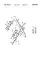
- FIG. 2is a perspective view of one form of surgical retractor assembly illustrative of an embodiment of the invention.
- a prior art retractor 10includes an elongated base bar 12 and a first leg 14 that extends from and is substantially normal to base bar 12. Leg 14 is fixed to or may be formed integrally with base bar 12. A first gripper 16 is mounted on first leg 14.
- a second leg 20has a proximal end 22 that is attached to a carriage 30 that is mounted for movement on and longitudinally of base bar 12.
- Leg 20extends substantially parallel to first leg 14.
- base bar 12is provided with a rack of teeth 28.
- the carriage 30is engaged with and movable along base bar 12.
- a handle 32is rotatably mounted on carriage 30.
- the inner rotatable end 34 of the handleis attached to a rotary gear (not shown) that engages rack teeth 28.
- the connection (not shown) between handle 32 and the aforesaid rotary gear (not shown)is such that rotation of the handle about its rotational axis will cause carriage 30 to move in one direction or an opposite direction along base bar 12, according to the direction of rotation of handle 32., so as to move second leg 20 toward or away from first leg 14.
- the first gripper 16comprises a channel member 36 and each of the grippers 24, 26 includes an arm 38 having curved fingers 40 at its free end.
- Grippers 16, 24, and 26are sized and shaped so as to be able to engage and retract ribs or other human or animal bone or tissue.
- an illustrative embodiment of the inventionincludes, in combination with a retractor 10' of the type described hereinabove, a U-shaped flexible spring-like rail 50 having first and second opposite ends 52 and 54 that are received in two sleeves 53 and 55 respectively.
- sleeve 53is fixed to a modified gripper 16' that is carried by the first leg 14, while sleeve 55 is fixed to gripper 24.
- Gripper 16'may be fixed to leg 14 or may be sized and shaped so as to be slidable thereon toward and away from base bar 12.
- Rail 50may be made of a metal alloy or other material and comprises a bent or arcuate portion 56 that extends toward, and is in part proximate to, the base bar 12. Rail 50 is movable relative to sleeves 53 and 55. Preferably rail 50 has a circular cross-section. Rail 50 also is sufficiently resilient to allow its ends 52 and 54 to move toward or away from one another in accordance with corresponding movement of leg 20 relative to leg 14. The degree of stiffness of rail 50 is such as to accommodate but not prevent relative movement of leg 20 relative to leg 14.
- sleeve 55is provided with a tapped hole that receives a thumb-style lock screw 65 that can be screwed down into tight engagement with rail 50, thereby locking the rail against movement relative to that sleeve and gripper 14.
- the other sleeve 53may but need not have a like lock screw arrangement.
- An accessory support member 60is slidably disposed on rail 50 and is manually movable on the rail between a position adjacent first leg 14 and gripper 16' (as shown in FIG. 2) to a position adjacent second leg 20, that is, along an approximately 180° sweep.
- Support member 60has a hole of circular cross-section sized to make a close fit with rail 50 while allowing it to slide or rotate retlative to the rail.
- the accessory support member 60includes a support arm 62 to which is connected an accessory A, which preferably is a TV camera, but may be a light source or other helpful accessory for the task at hand.
- the operative end E of the accessorythat is, the lens portion of a camera, or the light emitting portion of a light source, is disposed between first and second legs 14, 20 and is directed toward a surgical site S and, upon movement of accessory support member 60, changes its position between first and second legs 14, 20 but remains directed toward surgical site S.
- the grippers 16 and 24, 26,are engaged with the tissue or ribs at the sides of an opening in the chest wall.
- grippers 16 and 24, 26are caused to move relatively away from each other to effectively expand and maintain the opening in the chest wall.
- the position of the TV camera or other accessory Amay be changed by sliding support member 60 along rail 50 or by rotating the support member on the rail so as to tilt the camera or other accessory A to a desired angular position. If it is found helpful to further spread legs 14, 20, or to bring legs 14, 20 closer together, rail 50 is sufficiently flexible to bend with the leg movement.
- lock screw 65 in sleeve 55rail 50 may be shifted in sleeve 55 (to accommodate changes in the distance between legs 14 and 20) and then again fixed to prevent further movement by tightening down on lock screw 65.
- accessory support member 60is configured to make a tight sliding fit on rail 50, so that it can be slid manually along the rail but will retain its current position when released from the surgeon's hand.
- accessory support member 60with a manually-operated lock screw 63 that can be turned into tight engagement with rail 50 so as to lock the accessory support member 60 in a selected position.
- retractorand an accessory device support assembly
- the retractormay be a selected one of number of currently available retractors, and wherein the accessory device support is easily moved so as to maintain an operative end of an accessory device directed at a surgical site.
- accessory support member 60could be fixed permanently in a selected positon on rail 50.
- accessory support member 60could be fixed permanently in a selected positon on rail 50.
Landscapes
- Health & Medical Sciences (AREA)
- Surgery (AREA)
- Life Sciences & Earth Sciences (AREA)
- Heart & Thoracic Surgery (AREA)
- Engineering & Computer Science (AREA)
- Biomedical Technology (AREA)
- Nuclear Medicine, Radiotherapy & Molecular Imaging (AREA)
- Medical Informatics (AREA)
- Molecular Biology (AREA)
- Animal Behavior & Ethology (AREA)
- General Health & Medical Sciences (AREA)
- Public Health (AREA)
- Veterinary Medicine (AREA)
- Pathology (AREA)
- Oral & Maxillofacial Surgery (AREA)
- Surgical Instruments (AREA)
Abstract
Description
Claims (17)
Priority Applications (5)
| Application Number | Priority Date | Filing Date | Title |
|---|---|---|---|
| US08/778,974US5697891A (en) | 1997-01-06 | 1997-01-06 | Surgical retractor with accessory support |
| PCT/US1997/019065WO1998030150A1 (en) | 1997-01-06 | 1997-10-21 | Surgical retractor with accessory support |
| EP97913726AEP0928162A4 (en) | 1997-01-06 | 1997-10-21 | Surgical retractor with accessory support |
| CA002248379ACA2248379A1 (en) | 1997-01-06 | 1997-10-21 | Surgical retractor with accessory support |
| JP10530845AJP2000507146A (en) | 1997-01-06 | 1997-10-21 | Surgical retractor with accessory support |
Applications Claiming Priority (1)
| Application Number | Priority Date | Filing Date | Title |
|---|---|---|---|
| US08/778,974US5697891A (en) | 1997-01-06 | 1997-01-06 | Surgical retractor with accessory support |
Publications (1)
| Publication Number | Publication Date |
|---|---|
| US5697891Atrue US5697891A (en) | 1997-12-16 |
Family
ID=25114922
Family Applications (1)
| Application Number | Title | Priority Date | Filing Date |
|---|---|---|---|
| US08/778,974Expired - LifetimeUS5697891A (en) | 1997-01-06 | 1997-01-06 | Surgical retractor with accessory support |
Country Status (5)
| Country | Link |
|---|---|
| US (1) | US5697891A (en) |
| EP (1) | EP0928162A4 (en) |
| JP (1) | JP2000507146A (en) |
| CA (1) | CA2248379A1 (en) |
| WO (1) | WO1998030150A1 (en) |
Cited By (47)
| Publication number | Priority date | Publication date | Assignee | Title |
|---|---|---|---|---|
| US6033362A (en)* | 1997-04-25 | 2000-03-07 | Beth Israel Deaconess Medical Center | Surgical retractor and method of use |
| US6113536A (en)* | 1998-09-30 | 2000-09-05 | A-Med Systems, Inc. | Device and method of attaching a blood pump and tubes to a surgical retractor |
| WO2001035848A1 (en)* | 1999-11-16 | 2001-05-25 | Norbert Lemke | Image recording device to be used in a sterile area for visually monitoring and documenting a surgical intervention |
| US6322500B1 (en)* | 1996-12-23 | 2001-11-27 | University Of Massachusetts | Minimally invasive surgical apparatus |
| EP1192905A1 (en)* | 2000-10-02 | 2002-04-03 | Aesculap AG & Co. KG | Surgical retractor |
| US6458079B1 (en)* | 1997-04-25 | 2002-10-01 | Beth Israel Deaconess Medical Center | Surgical retractor and method of use |
| US20040172105A1 (en)* | 2003-01-31 | 2004-09-02 | Vankoski Stephen J. | Lit retractor |
| EP1304962A4 (en)* | 1999-07-27 | 2005-10-12 | Res Surgical Pty Ltd | Surgical retractor |
| US20060272979A1 (en)* | 2005-06-07 | 2006-12-07 | Lubbers Lawrence M | Surgical Tray |
| US7235049B1 (en)* | 1997-04-25 | 2007-06-26 | Beth Israel Deaconess Medical Center | Surgical retractor and method of positioning an artery during surgery |
| US20070249932A1 (en)* | 2006-04-25 | 2007-10-25 | Shahinian Hrayr K | Remote manipulator with eyeballs |
| US20080021284A1 (en)* | 2006-07-19 | 2008-01-24 | Zimmer Spine, Inc. | Surgical access system and method of using the same |
| US20080161650A1 (en)* | 2006-07-19 | 2008-07-03 | Zimmer Spine, Inc. | Surgical access system and method of using the same |
| US8062107B1 (en)* | 2008-08-27 | 2011-11-22 | Sauer Curtis R | Hunting tool |
| US8540628B2 (en) | 2010-02-12 | 2013-09-24 | Covidien Lp | Expandable thoracic access port |
| US8574155B2 (en) | 2010-02-12 | 2013-11-05 | Covidien Lp | Expandable surgical access port |
| US8579810B2 (en) | 2010-02-12 | 2013-11-12 | Covidien Lp | Expandable thoracic access port |
| US8597180B2 (en) | 2010-08-12 | 2013-12-03 | Covidien Lp | Expandable thoracic access port |
| US20140031632A1 (en)* | 2011-03-28 | 2014-01-30 | J. Morita Manufacturing Corporation | Retractor |
| US8777849B2 (en) | 2010-02-12 | 2014-07-15 | Covidien Lp | Expandable thoracic access port |
| US8864658B2 (en) | 2010-08-12 | 2014-10-21 | Covidien Lp | Expandable surgical access port |
| US8882662B2 (en) | 2012-06-27 | 2014-11-11 | Camplex, Inc. | Interface for viewing video from cameras on a surgical visualization system |
| US8961409B2 (en) | 2011-12-07 | 2015-02-24 | Covidien Lp | Thoracic access assembly |
| US8961408B2 (en) | 2010-08-12 | 2015-02-24 | Covidien Lp | Expandable surgical access port |
| US9039610B2 (en) | 2011-05-19 | 2015-05-26 | Covidien Lp | Thoracic access port |
| US9119665B2 (en) | 2011-03-21 | 2015-09-01 | Covidien Lp | Thoracic access port including foldable anchor |
| US9247955B2 (en) | 2010-08-12 | 2016-02-02 | Covidien Lp | Thoracic access port |
| US9295375B2 (en) | 2012-09-27 | 2016-03-29 | Hrayr Karnig Shahinian | Programmable spectral source and design tool for 3D imaging using complementary bandpass filters |
| US9456735B2 (en) | 2012-09-27 | 2016-10-04 | Shahinian Karnig Hrayr | Multi-angle rear-viewing endoscope and method of operation thereof |
| US9549667B2 (en) | 2007-12-18 | 2017-01-24 | Harish M. MANOHARA | Endoscope and system and method of operation thereof |
| CN106344086A (en)* | 2016-10-29 | 2017-01-25 | 孙丽君 | a sternum spreader |
| US9642606B2 (en) | 2012-06-27 | 2017-05-09 | Camplex, Inc. | Surgical visualization system |
| US9782159B2 (en) | 2013-03-13 | 2017-10-10 | Camplex, Inc. | Surgical visualization systems |
| US9861261B2 (en) | 2014-03-14 | 2018-01-09 | Hrayr Karnig Shahinian | Endoscope system and method of operation thereof |
| US9867531B2 (en) | 2012-12-26 | 2018-01-16 | Verathon Inc. | Video retractor |
| US10028651B2 (en) | 2013-09-20 | 2018-07-24 | Camplex, Inc. | Surgical visualization systems and displays |
| US10568499B2 (en) | 2013-09-20 | 2020-02-25 | Camplex, Inc. | Surgical visualization systems and displays |
| US10702353B2 (en) | 2014-12-05 | 2020-07-07 | Camplex, Inc. | Surgical visualizations systems and displays |
| US10918455B2 (en) | 2017-05-08 | 2021-02-16 | Camplex, Inc. | Variable light source |
| US10966798B2 (en) | 2015-11-25 | 2021-04-06 | Camplex, Inc. | Surgical visualization systems and displays |
| US10987128B2 (en) | 2017-03-22 | 2021-04-27 | Covidien Lp | Cannula assembly |
| US11141191B2 (en) | 2020-01-15 | 2021-10-12 | Covidien Lp | Surgical access assembly |
| US11154378B2 (en) | 2015-03-25 | 2021-10-26 | Camplex, Inc. | Surgical visualization systems and displays |
| WO2022005410A1 (en)* | 2020-06-30 | 2022-01-06 | Osman Aydin | Innovation in a cartridge |
| US11529042B2 (en) | 2009-11-13 | 2022-12-20 | Hrayr Karnig Shahinian | Stereo imaging miniature endoscope with single imaging and conjugated multi-bandpass filters |
| US11559295B2 (en)* | 2012-09-26 | 2023-01-24 | DePuy Synthes Products, Inc. | NIR/red light for lateral neuroprotection |
| US12251130B2 (en) | 2021-05-03 | 2025-03-18 | Covidien Lp | Surgical access device having a balloon and methods for manufacturing the same |
Families Citing this family (1)
| Publication number | Priority date | Publication date | Assignee | Title |
|---|---|---|---|---|
| JP5933865B1 (en) | 2014-07-23 | 2016-06-15 | オリンパス株式会社 | Medical dilator |
Citations (5)
| Publication number | Priority date | Publication date | Assignee | Title |
|---|---|---|---|---|
| FR432042A (en)* | 1911-07-07 | 1911-11-25 | Societe J Gautier Et R Toury | Mouth opener |
| US1036497A (en)* | 1912-03-23 | 1912-08-20 | Ernst T Krebs | Mouth-gag. |
| GB168216A (en)* | 1920-07-07 | 1921-09-01 | William J Cameron | Improvements in and relating to gagging-appliances and tongue depressors |
| US1706500A (en)* | 1927-08-01 | 1929-03-26 | Henry J Smith | Surgical retractor |
| US4627421A (en)* | 1984-08-03 | 1986-12-09 | Symbas Panagiotis N | Sternal retractor |
Family Cites Families (2)
| Publication number | Priority date | Publication date | Assignee | Title |
|---|---|---|---|---|
| FR1019217A (en)* | 1950-03-10 | 1953-01-19 | Improvements made to surgical retractors, especially those for endothoracic operations | |
| US5167223A (en)* | 1989-09-08 | 1992-12-01 | Tibor Koros | Heart valve retractor and sternum spreader surgical instrument |
- 1997
- 1997-01-06USUS08/778,974patent/US5697891A/ennot_activeExpired - Lifetime
- 1997-10-21WOPCT/US1997/019065patent/WO1998030150A1/ennot_activeApplication Discontinuation
- 1997-10-21EPEP97913726Apatent/EP0928162A4/ennot_activeWithdrawn
- 1997-10-21JPJP10530845Apatent/JP2000507146A/enactivePending
- 1997-10-21CACA002248379Apatent/CA2248379A1/ennot_activeAbandoned
Patent Citations (5)
| Publication number | Priority date | Publication date | Assignee | Title |
|---|---|---|---|---|
| FR432042A (en)* | 1911-07-07 | 1911-11-25 | Societe J Gautier Et R Toury | Mouth opener |
| US1036497A (en)* | 1912-03-23 | 1912-08-20 | Ernst T Krebs | Mouth-gag. |
| GB168216A (en)* | 1920-07-07 | 1921-09-01 | William J Cameron | Improvements in and relating to gagging-appliances and tongue depressors |
| US1706500A (en)* | 1927-08-01 | 1929-03-26 | Henry J Smith | Surgical retractor |
| US4627421A (en)* | 1984-08-03 | 1986-12-09 | Symbas Panagiotis N | Sternal retractor |
Cited By (85)
| Publication number | Priority date | Publication date | Assignee | Title |
|---|---|---|---|---|
| US6322500B1 (en)* | 1996-12-23 | 2001-11-27 | University Of Massachusetts | Minimally invasive surgical apparatus |
| US20030013941A1 (en)* | 1997-04-25 | 2003-01-16 | Beth Israel Deaconess Medical Center | Surgical Retractor |
| US6458079B1 (en)* | 1997-04-25 | 2002-10-01 | Beth Israel Deaconess Medical Center | Surgical retractor and method of use |
| US7468030B1 (en) | 1997-04-25 | 2008-12-23 | Beth Israel Deaconess Medical Center | Surgical retractor |
| US6033362A (en)* | 1997-04-25 | 2000-03-07 | Beth Israel Deaconess Medical Center | Surgical retractor and method of use |
| US7235049B1 (en)* | 1997-04-25 | 2007-06-26 | Beth Israel Deaconess Medical Center | Surgical retractor and method of positioning an artery during surgery |
| US7736308B2 (en) | 1997-04-25 | 2010-06-15 | Teleflex-Ct Devices Incorporated | Surgical retractor |
| US6113536A (en)* | 1998-09-30 | 2000-09-05 | A-Med Systems, Inc. | Device and method of attaching a blood pump and tubes to a surgical retractor |
| EP1304962A4 (en)* | 1999-07-27 | 2005-10-12 | Res Surgical Pty Ltd | Surgical retractor |
| US7276024B1 (en) | 1999-07-27 | 2007-10-02 | Research Surgical Pty Ltd. | Surgical retractor |
| WO2001035848A1 (en)* | 1999-11-16 | 2001-05-25 | Norbert Lemke | Image recording device to be used in a sterile area for visually monitoring and documenting a surgical intervention |
| EP1192905A1 (en)* | 2000-10-02 | 2002-04-03 | Aesculap AG & Co. KG | Surgical retractor |
| US20040172105A1 (en)* | 2003-01-31 | 2004-09-02 | Vankoski Stephen J. | Lit retractor |
| US7503894B2 (en)* | 2003-01-31 | 2009-03-17 | Zimmer Technology, Inc. | Lit retractor |
| US20060272979A1 (en)* | 2005-06-07 | 2006-12-07 | Lubbers Lawrence M | Surgical Tray |
| US7601119B2 (en) | 2006-04-25 | 2009-10-13 | Hrayr Kamig Shahinian | Remote manipulator with eyeballs |
| US20070249932A1 (en)* | 2006-04-25 | 2007-10-25 | Shahinian Hrayr K | Remote manipulator with eyeballs |
| US8262569B2 (en)* | 2006-07-19 | 2012-09-11 | Zimmer Spine, Inc. | Surgical access system and method of using the same |
| US20080021284A1 (en)* | 2006-07-19 | 2008-01-24 | Zimmer Spine, Inc. | Surgical access system and method of using the same |
| US7892174B2 (en)* | 2006-07-19 | 2011-02-22 | Zimmer Spine, Inc. | Surgical access system and method of using the same |
| US20080161650A1 (en)* | 2006-07-19 | 2008-07-03 | Zimmer Spine, Inc. | Surgical access system and method of using the same |
| US9549667B2 (en) | 2007-12-18 | 2017-01-24 | Harish M. MANOHARA | Endoscope and system and method of operation thereof |
| US10278568B2 (en) | 2007-12-18 | 2019-05-07 | Harish M. MANOHARA | Endoscope and system and method of operation thereof |
| US8062107B1 (en)* | 2008-08-27 | 2011-11-22 | Sauer Curtis R | Hunting tool |
| US11529042B2 (en) | 2009-11-13 | 2022-12-20 | Hrayr Karnig Shahinian | Stereo imaging miniature endoscope with single imaging and conjugated multi-bandpass filters |
| US8540628B2 (en) | 2010-02-12 | 2013-09-24 | Covidien Lp | Expandable thoracic access port |
| US8574155B2 (en) | 2010-02-12 | 2013-11-05 | Covidien Lp | Expandable surgical access port |
| US8579810B2 (en) | 2010-02-12 | 2013-11-12 | Covidien Lp | Expandable thoracic access port |
| US8777849B2 (en) | 2010-02-12 | 2014-07-15 | Covidien Lp | Expandable thoracic access port |
| US9402613B2 (en) | 2010-02-12 | 2016-08-02 | Covidien Lp | Expandable thoracic access port |
| US8597180B2 (en) | 2010-08-12 | 2013-12-03 | Covidien Lp | Expandable thoracic access port |
| US8961408B2 (en) | 2010-08-12 | 2015-02-24 | Covidien Lp | Expandable surgical access port |
| US9597114B2 (en) | 2010-08-12 | 2017-03-21 | Covidien Lp | Expandable surgical access port |
| US9247955B2 (en) | 2010-08-12 | 2016-02-02 | Covidien Lp | Thoracic access port |
| US9168031B2 (en) | 2010-08-12 | 2015-10-27 | Covidien Lp | Expandable thoracic access port |
| US8864658B2 (en) | 2010-08-12 | 2014-10-21 | Covidien Lp | Expandable surgical access port |
| US9549722B2 (en) | 2011-03-21 | 2017-01-24 | Covidien Lp | Thoracic access port including foldable anchor |
| US9119665B2 (en) | 2011-03-21 | 2015-09-01 | Covidien Lp | Thoracic access port including foldable anchor |
| US20140031632A1 (en)* | 2011-03-28 | 2014-01-30 | J. Morita Manufacturing Corporation | Retractor |
| US10420541B2 (en) | 2011-05-19 | 2019-09-24 | Covidien Lp | Thoracic access port |
| US9039610B2 (en) | 2011-05-19 | 2015-05-26 | Covidien Lp | Thoracic access port |
| US11375884B2 (en) | 2011-09-27 | 2022-07-05 | California Institute Of Technology | Multi-angle rear-viewing endoscope and method of operation thereof |
| US9713419B2 (en) | 2011-09-27 | 2017-07-25 | California Institute Of Technology | Programmable spectral source and design tool for 3D imaging using complementary bandpass filters |
| US9629657B2 (en) | 2011-12-07 | 2017-04-25 | Covidien Lp | Thoracic access assembly |
| US8961409B2 (en) | 2011-12-07 | 2015-02-24 | Covidien Lp | Thoracic access assembly |
| US9681796B2 (en) | 2012-06-27 | 2017-06-20 | Camplex, Inc. | Interface for viewing video from cameras on a surgical visualization system |
| US10925472B2 (en) | 2012-06-27 | 2021-02-23 | Camplex, Inc. | Binocular viewing assembly for a surgical visualization system |
| US9615728B2 (en) | 2012-06-27 | 2017-04-11 | Camplex, Inc. | Surgical visualization system with camera tracking |
| US9642606B2 (en) | 2012-06-27 | 2017-05-09 | Camplex, Inc. | Surgical visualization system |
| US11166706B2 (en) | 2012-06-27 | 2021-11-09 | Camplex, Inc. | Surgical visualization systems |
| US11889976B2 (en) | 2012-06-27 | 2024-02-06 | Camplex, Inc. | Surgical visualization systems |
| US9723976B2 (en) | 2012-06-27 | 2017-08-08 | Camplex, Inc. | Optics for video camera on a surgical visualization system |
| US11129521B2 (en) | 2012-06-27 | 2021-09-28 | Camplex, Inc. | Optics for video camera on a surgical visualization system |
| US11389146B2 (en) | 2012-06-27 | 2022-07-19 | Camplex, Inc. | Surgical visualization system |
| US10925589B2 (en) | 2012-06-27 | 2021-02-23 | Camplex, Inc. | Interface for viewing video from cameras on a surgical visualization system |
| US9936863B2 (en) | 2012-06-27 | 2018-04-10 | Camplex, Inc. | Optical assembly providing a surgical microscope view for a surgical visualization system |
| US10022041B2 (en) | 2012-06-27 | 2018-07-17 | Camplex, Inc. | Hydraulic system for surgical applications |
| US9216068B2 (en) | 2012-06-27 | 2015-12-22 | Camplex, Inc. | Optics for video cameras on a surgical visualization system |
| US9629523B2 (en) | 2012-06-27 | 2017-04-25 | Camplex, Inc. | Binocular viewing assembly for a surgical visualization system |
| US10231607B2 (en) | 2012-06-27 | 2019-03-19 | Camplex, Inc. | Surgical visualization systems |
| US8882662B2 (en) | 2012-06-27 | 2014-11-11 | Camplex, Inc. | Interface for viewing video from cameras on a surgical visualization system |
| US9492065B2 (en) | 2012-06-27 | 2016-11-15 | Camplex, Inc. | Surgical retractor with video cameras |
| US10555728B2 (en) | 2012-06-27 | 2020-02-11 | Camplex, Inc. | Surgical visualization system |
| US11559295B2 (en)* | 2012-09-26 | 2023-01-24 | DePuy Synthes Products, Inc. | NIR/red light for lateral neuroprotection |
| US9456735B2 (en) | 2012-09-27 | 2016-10-04 | Shahinian Karnig Hrayr | Multi-angle rear-viewing endoscope and method of operation thereof |
| US9295375B2 (en) | 2012-09-27 | 2016-03-29 | Hrayr Karnig Shahinian | Programmable spectral source and design tool for 3D imaging using complementary bandpass filters |
| US9867531B2 (en) | 2012-12-26 | 2018-01-16 | Verathon Inc. | Video retractor |
| US9782159B2 (en) | 2013-03-13 | 2017-10-10 | Camplex, Inc. | Surgical visualization systems |
| US10932766B2 (en) | 2013-05-21 | 2021-03-02 | Camplex, Inc. | Surgical visualization systems |
| US10568499B2 (en) | 2013-09-20 | 2020-02-25 | Camplex, Inc. | Surgical visualization systems and displays |
| US10881286B2 (en) | 2013-09-20 | 2021-01-05 | Camplex, Inc. | Medical apparatus for use with a surgical tubular retractor |
| US10028651B2 (en) | 2013-09-20 | 2018-07-24 | Camplex, Inc. | Surgical visualization systems and displays |
| US11147443B2 (en) | 2013-09-20 | 2021-10-19 | Camplex, Inc. | Surgical visualization systems and displays |
| US9861261B2 (en) | 2014-03-14 | 2018-01-09 | Hrayr Karnig Shahinian | Endoscope system and method of operation thereof |
| US10702353B2 (en) | 2014-12-05 | 2020-07-07 | Camplex, Inc. | Surgical visualizations systems and displays |
| US11154378B2 (en) | 2015-03-25 | 2021-10-26 | Camplex, Inc. | Surgical visualization systems and displays |
| US10966798B2 (en) | 2015-11-25 | 2021-04-06 | Camplex, Inc. | Surgical visualization systems and displays |
| CN106344086B (en)* | 2016-10-29 | 2018-11-09 | 侯建峰 | a sternum spreader |
| CN106344086A (en)* | 2016-10-29 | 2017-01-25 | 孙丽君 | a sternum spreader |
| US10987128B2 (en) | 2017-03-22 | 2021-04-27 | Covidien Lp | Cannula assembly |
| US11864792B2 (en) | 2017-03-22 | 2024-01-09 | Covidien Lp | Cannula assembly |
| US10918455B2 (en) | 2017-05-08 | 2021-02-16 | Camplex, Inc. | Variable light source |
| US11141191B2 (en) | 2020-01-15 | 2021-10-12 | Covidien Lp | Surgical access assembly |
| WO2022005410A1 (en)* | 2020-06-30 | 2022-01-06 | Osman Aydin | Innovation in a cartridge |
| US12251130B2 (en) | 2021-05-03 | 2025-03-18 | Covidien Lp | Surgical access device having a balloon and methods for manufacturing the same |
Also Published As
| Publication number | Publication date |
|---|---|
| CA2248379A1 (en) | 1998-07-16 |
| EP0928162A1 (en) | 1999-07-14 |
| JP2000507146A (en) | 2000-06-13 |
| EP0928162A4 (en) | 2000-03-22 |
| WO1998030150A1 (en) | 1998-07-16 |
Similar Documents
| Publication | Publication Date | Title |
|---|---|---|
| US5697891A (en) | Surgical retractor with accessory support | |
| US12232911B2 (en) | Instrument holder | |
| US8206293B2 (en) | Retractor | |
| US7744530B2 (en) | Surgical instrument holder | |
| US7147599B2 (en) | Surgical retractor with improved arms | |
| US5195506A (en) | Surgical retractor for puncture operation | |
| US5902233A (en) | Angling surgical retractor apparatus and method of retracting anatomy | |
| US6077286A (en) | Instrument with a bendable handle | |
| US8715175B2 (en) | Thoracic retractor | |
| US8460185B2 (en) | Articulated surgical retractor | |
| US8262569B2 (en) | Surgical access system and method of using the same | |
| US20060142644A1 (en) | Universal scissors joint apparatus | |
| US20020035313A1 (en) | Surgical instrument | |
| US20080021284A1 (en) | Surgical access system and method of using the same | |
| CA2075319A1 (en) | Handle for surgical instruments | |
| WO1998027869A1 (en) | Minimally invasive surgical apparatus and method | |
| US20070158513A1 (en) | Surgical clamp and tool support system | |
| US8753272B2 (en) | Low profile surgical retractor | |
| US9044184B2 (en) | Spreadable medical instrument for endoscopic interventions | |
| US9532771B2 (en) | Support coupling for surgical instrument | |
| US6979291B1 (en) | Surgical retractor having curved arms | |
| JP6941332B2 (en) | Surgical forceps cutting function addition instrument | |
| WO2007068128A1 (en) | A pair of tongs apt for soft tissue spreading | |
| CN1953713A (en) | Grip element for a surgical instrument |
Legal Events
| Date | Code | Title | Description |
|---|---|---|---|
| AS | Assignment | Owner name:VISTA MEDICAL TECHNOLOGIES, INC., CALIFORNIA Free format text:ASSIGNMENT OF ASSIGNORS INTEREST;ASSIGNOR:HORI, KOICHIRO;REEL/FRAME:008448/0303 Effective date:19970327 | |
| STCF | Information on status: patent grant | Free format text:PATENTED CASE | |
| CC | Certificate of correction | ||
| FEPP | Fee payment procedure | Free format text:PAT HOLDER CLAIMS SMALL ENTITY STATUS - SMALL BUSINESS (ORIGINAL EVENT CODE: SM02); ENTITY STATUS OF PATENT OWNER: LARGE ENTITY | |
| FEPP | Fee payment procedure | Free format text:PAYOR NUMBER ASSIGNED (ORIGINAL EVENT CODE: ASPN); ENTITY STATUS OF PATENT OWNER: LARGE ENTITY | |
| FPAY | Fee payment | Year of fee payment:4 | |
| FEPP | Fee payment procedure | Free format text:PAYOR NUMBER ASSIGNED (ORIGINAL EVENT CODE: ASPN); ENTITY STATUS OF PATENT OWNER: LARGE ENTITY Free format text:PAYER NUMBER DE-ASSIGNED (ORIGINAL EVENT CODE: RMPN); ENTITY STATUS OF PATENT OWNER: LARGE ENTITY | |
| FPAY | Fee payment | Year of fee payment:8 | |
| AS | Assignment | Owner name:VIKING SYSTEMS, INC., CALIFORNIA Free format text:ASSIGNMENT OF ASSIGNORS INTEREST;ASSIGNOR:IVOW, INC.;REEL/FRAME:018590/0035 Effective date:20061205 | |
| FPAY | Fee payment | Year of fee payment:12 | |
| FEPP | Fee payment procedure | Free format text:PAT HOLDER NO LONGER CLAIMS SMALL ENTITY STATUS, ENTITY STATUS SET TO UNDISCOUNTED (ORIGINAL EVENT CODE: STOL); ENTITY STATUS OF PATENT OWNER: LARGE ENTITY | |
| SULP | Surcharge for late payment | ||
| AS | Assignment | Owner name:JPMORGAN CHASE BANK, N.A., AS ADMINISTRATIVE AGENT Free format text:SECURITY AGREEMENT;ASSIGNOR:VIKING SYSTEMS, INC.;REEL/FRAME:030707/0012 Effective date:20130611 |