US5697583A - Radio frequency coupler for communication between adjacent railway cars - Google Patents
Radio frequency coupler for communication between adjacent railway carsDownload PDFInfo
- Publication number
- US5697583A US5697583AUS08/713,521US71352196AUS5697583AUS 5697583 AUS5697583 AUS 5697583AUS 71352196 AUS71352196 AUS 71352196AUS 5697583 AUS5697583 AUS 5697583A
- Authority
- US
- United States
- Prior art keywords
- antenna element
- radio frequency
- coupler housing
- antenna
- coupler
- Prior art date
- Legal status (The legal status is an assumption and is not a legal conclusion. Google has not performed a legal analysis and makes no representation as to the accuracy of the status listed.)
- Expired - Lifetime
Links
- 230000008878couplingEffects0.000claimsabstractdescription31
- 238000010168coupling processMethods0.000claimsabstractdescription31
- 238000005859coupling reactionMethods0.000claimsabstractdescription31
- 239000000758substrateSubstances0.000claimsdescription7
- 230000005540biological transmissionEffects0.000claimsdescription5
- 229910052751metalInorganic materials0.000claims1
- 230000002939deleterious effectEffects0.000description4
- 230000009977dual effectEffects0.000description4
- 238000002955isolationMethods0.000description4
- 230000015556catabolic processEffects0.000description3
- 230000001808coupling effectEffects0.000description3
- 238000006731degradation reactionMethods0.000description3
- 230000000694effectsEffects0.000description2
- RYGMFSIKBFXOCR-UHFFFAOYSA-NCopperChemical compound[Cu]RYGMFSIKBFXOCR-UHFFFAOYSA-N0.000description1
- 239000011358absorbing materialSubstances0.000description1
- 239000011889copper foilSubstances0.000description1
- 238000006880cross-coupling reactionMethods0.000description1
- 238000009713electroplatingMethods0.000description1
- 230000005294ferromagnetic effectEffects0.000description1
- 239000000463materialSubstances0.000description1
Images

Classifications
- B—PERFORMING OPERATIONS; TRANSPORTING
- B61—RAILWAYS
- B61L—GUIDING RAILWAY TRAFFIC; ENSURING THE SAFETY OF RAILWAY TRAFFIC
- B61L15/00—Indicators provided on the vehicle or train for signalling purposes
- B61L15/0018—Communication with or on the vehicle or train
- B61L15/0036—Conductor-based, e.g. using CAN-Bus, train-line or optical fibres
Definitions
- This inventionrelates to a radio frequency (RF) coupler, and in particular to an RF coupler which allows RF communications through free space between adjacent cars of a multi-car vehicle.
- RFradio frequency
- U.S. Pat. No. 5,435,505discloses a system wherein electronic communications between cars are effected by free space radio frequency couplings. Antennae are mounted in housings, which are in turn mounted in a fixed relationship to coupling arms for physically coupling the cars together whereby the housings, and therefore the antennas, are maintained in fixed relationship to each other.
- Such a systemdoes not allow for any relative movement of the coupling housings with respect to each other since it requires the use of coupling arms which are fixed in relation thereto.
- such a systemis limited insofar as it may only be used when the coupling arms of connected rail cars are maintained in strict fixed mechanical alignment, and does not allow for any relative movement of the coupling arms during operation of the system.
- the RF coupling devicecomprises a first coupler housing comprising a first antenna element, and a second coupler housing comprising a second antenna element.
- the second coupler housingis located in near proximity to the first coupler housing such that the second antenna element is located in near proximity to the first antenna element and is substantially in phase therewith so as to couple radio frequency energy through the free space therebetween.
- the first coupler housing and the second coupler housinghave at least one degree of freedom of movement therebetween. That is, the first and second coupler housings may move with respect to each other in any of the X, Y or Z axes without suffering deleterious effects in the transmission of the data signals.
- the present inventionallows for dual channel communication between cars by providing a first coupler housing comprising a first antenna element and a third antenna element, the first antenna element and the third antenna element configured so as to transceive separate channels of radio frequency energy substantially out of phase from each other.
- a second coupler housingcomprises a second antenna element and a fourth antenna element, the second coupler housing located in near proximity to the first coupler housing, the second antenna element and the fourth antenna element configured so as to transceive separate channels of radio frequency energy substantially out of phase from each other.
- the second antenna elementis located in near proximity to the first antenna element and substantially in phase therewith so as to couple a first channel of radio frequency energy therebetween
- the fourth antenna elementis located in near proximity to the third antenna element and substantially in phase therewith so as to couple a second channel of radio frequency energy therebetween.
- the first coupler housing and the second coupler housinghave at least one degree of freedom of movement therebetween.
- each of the carshas coupling arms for connecting the cars to each other, and wherein each of the cars further comprises radio frequency transceiving means for transmitting and receiving radio frequency waves representative of data communicated between the cars;
- the RF coupling device of the present inventionis implemented by mounting the first coupler housing on a coupler arm of a first car, the first coupler housing comprising a first antenna element and a third antenna element configured so as to transceive separate channels of radio frequency energy substantially out of phase from each other.
- the second coupler housingis mounted on a coupler arm of a second car, the second coupler housing comprising a second antenna element and a fourth antenna element and located in near proximity to the first coupler housing when the coupler arms of the cars are mechanically joined together.
- the second antenna element and the fourth antenna elementare configured so as to transceive separate channels of radio frequency energy substantially out of phase from each other.
- the second antenna elementis located in near proximity to the first antenna element and substantially in phase therewith so as to couple a first channel of radio frequency energy therebetween, and the fourth antenna element is located in near proximity to the third antenna element and substantially in phase therewith so as to couple a second channel of radio frequency energy therebetween.
- the first coupler housing and the second coupler housinghave at least one degree of translational freedom therebetween.
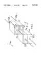
- FIG. 1is a perspective view of the RF coupler of the preferred embodiment of the present invention.
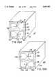
- FIG. 2(a)is a perspective view of a first coupler housing of the RF coupling device of FIG. 1;
- FIG. 2(b)is a perspective view of a second, mirror image coupler housing of the RF coupling device of FIG. 1;
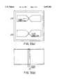
- FIG. 3(a)is a front face view of the coupler housing of FIG. 2(a);
- FIG. 3(b)is a top view of the coupler housing of FIG. 2(a), and
- FIG. 4is a side view of the RF coupler.
- FIG. 1illustrates a radio frequency (RF) coupling device 10 of the preferred embodiment of the present invention, comprising a first coupler housing 12 and a second coupler housing 112.
- the first and second coupler housings 12, 112are the same size and configuration and have antenna elements, to be described below, which face each other and are configured so as to be mirror images of each other in order to effect efficient transfer of RF signals between the coupler housings.
- the first coupler housing 12is shown in FIG. 2(a) and comprises a box-like enclosure 13 with a dielectric substrate 15 forming one face thereof.
- the dipole antenna elements 14, 16are formed by any means known in the art compatible with forming a flat antenna element, i.e. by copper foil, electroplating, and the like.
- Each dipole element 14, 16is comprised of a pair of oppositely disposed portions 14a, 14b and 16a, 16b as shown in FIG. 2. Strips of ferromagnetic radar absorbing material 18 are disposed on the substrate 15.
- the dipole antenna elements 14, 16are arranged so as to be substantially 180 degrees out of phase with each other by connecting each element to an associated coaxial cable transmission line (shown in FIGS. 3 and 4) in opposing fashion as shown by first feed point 22 on first antenna portion 14a and third feed point 24 on third antenna portion 16b.
- the outer shields of the coaxial lines associated with each dipole elementare connected at first antenna portion 14b and third antenna portion 16a, respectively.
- the propagation path for the RF signal fed to or from the first dipole element 14 via the first feed point 22is towards the left side
- the propagation path for the RF signal fed to the third dipole element 16 via the third feed point 24is towards the right side.
- the result of this configurationis that the dipole antenna elements 14 and 16 operate 180 degrees out of phase with each other. This configuration is advantageous since it allows dual channel operation at the same frequency with minimal deleterious coupling effects and thus maximum isolation between the channels.
- the second coupler housing 112is shown in FIG. 2(b) and is identical to the first coupler housing in FIG. 2(a), except that the antenna elements are mirror images of those in housing 12. That is, the feed point connections are on sides opposite to that of the first coupler housing to provide effective communications therebetween.
- the second coupler housing 112comprises a box-like enclosure 113 with a dielectric substrate 115 forming one face thereof.
- a pair of antenna elements 114 and 116which in the preferred embodiment are dipole elements, are mounted on the substrate 115 and are designated as second antenna element 114 and fourth antenna element 116.
- the dipole antenna elements 114, 116are formed in the same manner as dipole elements 14 and 16.
- Each dipole element 114, 116is comprised of a pair of oppositely disposed portions 114a, 114b and 116a, 116b as shown in FIG. 2(b).
- the dipole antenna elements 114, 116are arranged so as to be substantially 180 degrees out of phase with each other by connecting each element to an associated coaxial cable transmission line in opposing fashion as shown by second feed point 122 on second antenna portion 114b and fourth feed point 124 on fourth antenna portion 116a.
- the outer shields of the coaxial lines associated with each dipole elementare connected at second antenna portion 114a and fourth antenna portion 116b, respectively.
- dipole antenna elements 114 and 116operate 180 degrees out of phase with each other, and they are in phase with associated dipole elements 14 and 16, respectively.
- This configurationis advantageous since it allows dual channel operation at the same frequency with minimal deleterious coupling effects and thus maximum isolation between the channels.
- the coupler housings 12 and 112are brought in near proximity to and within the very near field of each other (i.e., approximately 0.1"), such as by attaching each to oppositely disposed coupler arms of a multi-car vehicle.
- An RF transmitteris connected via coax feed 1 to first antenna element 14, and an RF receiver is connected via coax feed 2 to second antenna element 114, thus forming channel A.
- an RF receiveris connected via coax feed 3 to third antenna element 16, and an RF transmitter is connected via coax feed 4 to fourth antenna element 116, thus forming channel B.
- Signalsmay be transferred along channels A and B at the same frequency in opposite directions without deleterious cross-coupling effects since the antenna elements of channel A are 180° out of phase with the antenna elements of channel B, thus forming a bi-directional system.
- a single channel coupling devicemay be implemented when only one channel of communications is required.
- the dual channel embodiment described hereinmay be used to transmit data in two different directions at the same time, or they may be used to transmit data in the same direction at different frequencies, and the like. Due to the advantages attained by operating the channels substantially out of phase with each other, isolation between the channels allows such flexibility in use as heretofore unrealized in the prior art.
- the designcan be substantially reduced by using materials with higher dielectric properties, which would decrease the size of the current design for a given frequency or allow the same size to be used for a lower frequency.
Landscapes
- Engineering & Computer Science (AREA)
- Mechanical Engineering (AREA)
- Details Of Aerials (AREA)
Abstract
Description
Claims (10)
Priority Applications (1)
| Application Number | Priority Date | Filing Date | Title |
|---|---|---|---|
| US08/713,521US5697583A (en) | 1996-09-13 | 1996-09-13 | Radio frequency coupler for communication between adjacent railway cars |
Applications Claiming Priority (1)
| Application Number | Priority Date | Filing Date | Title |
|---|---|---|---|
| US08/713,521US5697583A (en) | 1996-09-13 | 1996-09-13 | Radio frequency coupler for communication between adjacent railway cars |
Publications (1)
| Publication Number | Publication Date |
|---|---|
| US5697583Atrue US5697583A (en) | 1997-12-16 |
Family
ID=24866470
Family Applications (1)
| Application Number | Title | Priority Date | Filing Date |
|---|---|---|---|
| US08/713,521Expired - LifetimeUS5697583A (en) | 1996-09-13 | 1996-09-13 | Radio frequency coupler for communication between adjacent railway cars |
Country Status (1)
| Country | Link |
|---|---|
| US (1) | US5697583A (en) |
Cited By (11)
| Publication number | Priority date | Publication date | Assignee | Title |
|---|---|---|---|---|
| DE19918655A1 (en)* | 1999-04-16 | 2000-10-19 | Siemens Ag | Arrangement for operating selected electrical loads on railway vehicles |
| DE19934640C1 (en)* | 1999-07-23 | 2000-11-30 | Honeywell Ag | Communication and monitoring device for train uses radar couplings between radar device within locomotive and each successive wagon |
| US20040026575A1 (en)* | 2002-08-12 | 2004-02-12 | Alcatel | Electronic drawbar |
| US6789004B2 (en)* | 2000-07-14 | 2004-09-07 | Beltpack Corporation | Remote control system for locomotives |
| WO2007008756A1 (en)* | 2005-07-07 | 2007-01-18 | Geofocus Llc | Contactless data communications coupling |
| US20090195344A1 (en)* | 2006-01-06 | 2009-08-06 | Kinkisharyo International, Llc | Contactless data communications coupler |
| US20110172856A1 (en)* | 2010-01-08 | 2011-07-14 | Wabtec Holding Corp. | Short Headway Communications Based Train Control System |
| WO2013139923A3 (en)* | 2012-03-21 | 2014-09-12 | Schleifring Und Apparatebau Gmbh | Rail vehicle coupling device having a contactless connector |
| CN107168316A (en)* | 2017-05-23 | 2017-09-15 | 华南理工大学 | A kind of multiple AGV scheduling system based on single-direction and dual-direction mixed path |
| US10919548B2 (en) | 2018-08-20 | 2021-02-16 | Mohd B. Malik | Non-stop train with attaching and detaching train cars |
| SE2350325A1 (en)* | 2023-03-23 | 2024-03-26 | Dellner Couplers Ab | Central buffer coupler, signal transceiver, vehicle member and computer-implemented method |
Citations (5)
| Publication number | Priority date | Publication date | Assignee | Title |
|---|---|---|---|---|
| US3696758A (en)* | 1969-12-18 | 1972-10-10 | Genisco Technology Corp | Locomotive signaling and control system |
| US4582280A (en)* | 1983-09-14 | 1986-04-15 | Harris Corporation | Railroad communication system |
| US4723737A (en)* | 1984-10-18 | 1988-02-09 | Matra Transport | Process and device for transmitting data between vehicles moving over a track |
| US5182570A (en)* | 1989-11-13 | 1993-01-26 | X-Cyte Inc. | End fed flat antenna |
| US5351919A (en)* | 1993-03-29 | 1994-10-04 | Primetech Electroniques Inc. | Trainline communication link using radio frequency signal |
- 1996
- 1996-09-13USUS08/713,521patent/US5697583A/ennot_activeExpired - Lifetime
Patent Citations (6)
| Publication number | Priority date | Publication date | Assignee | Title |
|---|---|---|---|---|
| US3696758A (en)* | 1969-12-18 | 1972-10-10 | Genisco Technology Corp | Locomotive signaling and control system |
| US4582280A (en)* | 1983-09-14 | 1986-04-15 | Harris Corporation | Railroad communication system |
| US4723737A (en)* | 1984-10-18 | 1988-02-09 | Matra Transport | Process and device for transmitting data between vehicles moving over a track |
| US5182570A (en)* | 1989-11-13 | 1993-01-26 | X-Cyte Inc. | End fed flat antenna |
| US5351919A (en)* | 1993-03-29 | 1994-10-04 | Primetech Electroniques Inc. | Trainline communication link using radio frequency signal |
| US5435505A (en)* | 1993-03-29 | 1995-07-25 | Primetech Electroniques Inc. | Electronic communications radio frequency coupler for multi-car vehicle |
Cited By (19)
| Publication number | Priority date | Publication date | Assignee | Title |
|---|---|---|---|---|
| DE19918655A1 (en)* | 1999-04-16 | 2000-10-19 | Siemens Ag | Arrangement for operating selected electrical loads on railway vehicles |
| DE19934640C1 (en)* | 1999-07-23 | 2000-11-30 | Honeywell Ag | Communication and monitoring device for train uses radar couplings between radar device within locomotive and each successive wagon |
| US6789004B2 (en)* | 2000-07-14 | 2004-09-07 | Beltpack Corporation | Remote control system for locomotives |
| US7263415B2 (en) | 2002-08-12 | 2007-08-28 | Thales | Electronic drawbar |
| US20040026575A1 (en)* | 2002-08-12 | 2004-02-12 | Alcatel | Electronic drawbar |
| US7027899B2 (en) | 2002-08-12 | 2006-04-11 | Alcatel | Electronic drawbar |
| US20060129287A1 (en)* | 2002-08-12 | 2006-06-15 | Alcatel | Electronic drawbar |
| EP1391365A1 (en)* | 2002-08-12 | 2004-02-25 | Alcatel | Electronic coupling device |
| US20100044333A1 (en)* | 2005-07-07 | 2010-02-25 | Marvel Dennis K | Contactless data communications coupling |
| WO2007008756A1 (en)* | 2005-07-07 | 2007-01-18 | Geofocus Llc | Contactless data communications coupling |
| US20090195344A1 (en)* | 2006-01-06 | 2009-08-06 | Kinkisharyo International, Llc | Contactless data communications coupler |
| US20110172856A1 (en)* | 2010-01-08 | 2011-07-14 | Wabtec Holding Corp. | Short Headway Communications Based Train Control System |
| US8428798B2 (en) | 2010-01-08 | 2013-04-23 | Wabtec Holding Corp. | Short headway communications based train control system |
| WO2013139923A3 (en)* | 2012-03-21 | 2014-09-12 | Schleifring Und Apparatebau Gmbh | Rail vehicle coupling device having a contactless connector |
| CN107168316A (en)* | 2017-05-23 | 2017-09-15 | 华南理工大学 | A kind of multiple AGV scheduling system based on single-direction and dual-direction mixed path |
| CN107168316B (en)* | 2017-05-23 | 2020-09-22 | 华南理工大学 | Multi-AGV dispatching system based on single-direction and two-direction mixed paths |
| US10919548B2 (en) | 2018-08-20 | 2021-02-16 | Mohd B. Malik | Non-stop train with attaching and detaching train cars |
| SE2350325A1 (en)* | 2023-03-23 | 2024-03-26 | Dellner Couplers Ab | Central buffer coupler, signal transceiver, vehicle member and computer-implemented method |
| SE545948C2 (en)* | 2023-03-23 | 2024-03-26 | Dellner Couplers Ab | Central buffer coupler, signal transceiver, vehicle member and computer-implemented method |
Similar Documents
| Publication | Publication Date | Title |
|---|---|---|
| EP2795716B1 (en) | Contactless connector | |
| USRE36076E (en) | Vehicle antenna system | |
| US4658259A (en) | On-glass antenna | |
| US5697583A (en) | Radio frequency coupler for communication between adjacent railway cars | |
| US12126070B2 (en) | Antenna module and communication device equipped with the same | |
| JP6868462B2 (en) | Wireless relay device | |
| EP3357167B1 (en) | In-band full-duplex complementary antenna | |
| KR20140105838A (en) | Waveguide structure for a contactless connector | |
| CN102195114A (en) | High-frequency coupler and communication device | |
| WO2018057173A1 (en) | Highly isolated monopole antenna system | |
| JP3281193B2 (en) | Microwave repeater | |
| US11949165B2 (en) | Antenna device and communication method | |
| EP4352882A1 (en) | Wireless interconnect for high-rate data transfer | |
| US6671463B2 (en) | Arrangement for transmitting, radiating and receiving high-frequency signals | |
| JP3181326B2 (en) | Microstrip and array antennas | |
| KR100883954B1 (en) | Circularly polarized antenna, repeater antenna, repeater and mobile communication system using same | |
| US20020109558A1 (en) | Device for propagating radio frequency signals in planar circuits | |
| CN113746569A (en) | Calibration device, base station antenna and communication assembly | |
| JPH03182103A (en) | Phased array antenna | |
| EP4607232A1 (en) | Synchronizing of distributed radar units | |
| WO2023106860A1 (en) | Wireless interconnect for high-rate data transfer | |
| JPS6124334A (en) | Radio communication equipment | |
| CN114824751A (en) | Directional antenna and vehicle comprising such a directional antenna | |
| CN116073121A (en) | Suspension strip line structure, base station antenna and base station | |
| KR20080100310A (en) | Circularly polarized antenna, repeater antenna and repeater and mobile communication system using same |
Legal Events
| Date | Code | Title | Description |
|---|---|---|---|
| AS | Assignment | Owner name:DORNE & MARGOLIN, INC., NEW YORK Free format text:ASSIGNMENT OF ASSIGNORS INTEREST;ASSIGNOR:KANE, MICHAEL;REEL/FRAME:008234/0632 Effective date:19960913 | |
| STCF | Information on status: patent grant | Free format text:PATENTED CASE | |
| AS | Assignment | Owner name:AIL SYSTEMS, INC., NEW YORK Free format text:STOCK PURCHASE AGREEMENT;ASSIGNORS:UNITED CAPITAL CORP.;METEX CORPORATION;REEL/FRAME:010033/0128 Effective date:19971120 | |
| FPAY | Fee payment | Year of fee payment:4 | |
| AS | Assignment | Owner name:CITIBANK, N.A., NEW YORK Free format text:SECURITY AGREEMENT;ASSIGNOR:AIL SYSTEMS, INC.;REEL/FRAME:013496/0795 Effective date:20021108 | |
| FPAY | Fee payment | Year of fee payment:8 | |
| AS | Assignment | Owner name:AIL SYSTEMS, INC., NEW YORK Free format text:RELEASE BY SECURED PARTY;ASSIGNOR:CITIBANK, N.A.;REEL/FRAME:020617/0842 Effective date:20071220 | |
| FPAY | Fee payment | Year of fee payment:12 | |
| AS | Assignment | Owner name:ITT MANUFACTURING ENTERPRISES, LLC, DELAWARE Free format text:ASSIGNMENT OF ASSIGNORS INTEREST;ASSIGNOR:EDO CORPORATION, FORMERLY AIL SYSTEMS, INC.;REEL/FRAME:027069/0825 Effective date:20111014 | |
| AS | Assignment | Owner name:EXELIS INC., VIRGINIA Free format text:ASSIGNMENT OF ASSIGNORS INTEREST;ASSIGNOR:ITT MANUFACTURING ENTERPRISES LLC (FORMERLY KNOWN AS ITT MANUFACTURING ENTERPRISES, INC.);REEL/FRAME:029152/0198 Effective date:20111221 | |
| AS | Assignment | Owner name:HARRIS CORPORATION, FLORIDA Free format text:MERGER;ASSIGNOR:EXELIS INC.;REEL/FRAME:039362/0534 Effective date:20151223 |