US5697538A - Holster for a portable communication device - Google Patents
Holster for a portable communication deviceDownload PDFInfo
- Publication number
- US5697538A US5697538AUS08/740,937US74093796AUS5697538AUS 5697538 AUS5697538 AUS 5697538AUS 74093796 AUS74093796 AUS 74093796AUS 5697538 AUS5697538 AUS 5697538A
- Authority
- US
- United States
- Prior art keywords
- communication device
- portable communication
- back wall
- holster
- sidewalls
- Prior art date
- Legal status (The legal status is an assumption and is not a legal conclusion. Google has not performed a legal analysis and makes no representation as to the accuracy of the status listed.)
- Expired - Lifetime
Links
Images


Classifications
- G—PHYSICS
- G08—SIGNALLING
- G08B—SIGNALLING OR CALLING SYSTEMS; ORDER TELEGRAPHS; ALARM SYSTEMS
- G08B3/00—Audible signalling systems; Audible personal calling systems
- G08B3/10—Audible signalling systems; Audible personal calling systems using electric transmission; using electromagnetic transmission
- G08B3/1008—Personal calling arrangements or devices, i.e. paging systems
- G08B3/1016—Personal calling arrangements or devices, i.e. paging systems using wireless transmission
- G08B3/1025—Paging receivers with audible signalling details
- G08B3/1058—Pager holders or housings
- Y—GENERAL TAGGING OF NEW TECHNOLOGICAL DEVELOPMENTS; GENERAL TAGGING OF CROSS-SECTIONAL TECHNOLOGIES SPANNING OVER SEVERAL SECTIONS OF THE IPC; TECHNICAL SUBJECTS COVERED BY FORMER USPC CROSS-REFERENCE ART COLLECTIONS [XRACs] AND DIGESTS
- Y10—TECHNICAL SUBJECTS COVERED BY FORMER USPC
- Y10S—TECHNICAL SUBJECTS COVERED BY FORMER USPC CROSS-REFERENCE ART COLLECTIONS [XRACs] AND DIGESTS
- Y10S224/00—Package and article carriers
- Y10S224/929—Article carrier for electrical device
- Y10S224/93—Attached to animate bearer
Definitions
- This inventionis directed to a holster for carrying a portable communication device.
- Holstersare commonly used to carry PCD's (Portable Communication Devices) such as pagers and other forms of messaging products.
- a typical holsterincludes a clip that allows a user to carry the holster on the user's belt or on another article of clothing.
- PCD'scome with a cover that can be flipped open to reveal a keyboard or other controls.
- Conventional holsterscan hold such a PCD, but they do not permit the PCD's cover to be opened while it resides in the holster. Consequently, the PCD cannot be manipulated by the user while it is in its holster. It would be desirable if a covered PCD could be opened while in its holster, but only if the PCD were held securely enough in the holster to avoid accidental release.
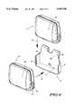
- FIG. 1is a front perspective view of a holster according to the invention
- FIG. 2is a rear perspective view of the holster shown in FIG. 1;
- FIG. 3is an enlarged view of a locking protrusion carried by the back wall of the holster
- FIG. 4is a side view of the holster's belt clip, showing the clip engaged with a belt;
- FIG. 5is another side view of the holster's belt clip, showing the clip engaged with clothing
- FIG. 6shows the holster and how a PCD can be inserted into the holster, either vertically or laterally;
- FIG. 7shows a PCP carried in the holster
- FIG. 8shows a PCD in the holster and with the PCD's cover opened.
- FIGS. 1 and 2show a holster 10 that is constructed in accordance with the invention to overcome the above-noted deficiencies of conventional holsters.
- the illustrated holsteris preferably a one-piece housing 12 that has a substantially planar back wall 14 that extends for substantially the full height of the holster.
- This back wallhas outer edges 16 that extend downwardly and outwardly to meet a pair of sidewalls 18 that are formed integrally with the back wall 14.
- the sidewalls 18extend substantially perpendicularly from the back wall 14 and are substantially parallel to each other.
- the vertical height of the sidewalls 18(as viewed in FIG. 1) is approximately one-half the overall height of the holster.
- the sidewalls 18are outwardly deflectable for receiving and holding a PCD.
- the depth D of the sidewalls 18can be less than the depth of a PCD that is to be held by the holster 10, thus permitting the held PCD to extend beyond the furthest lateral reach of the sidewalls 18. This is particularly advantageous for a PCD that has a cover and/or controls that are to be accessible to a user while the PCD is in the holster.
- the sidewalls 18 and the back wall 14merge at the bottom of the holster to form an integral bottom ledge 20 located between the sidewalls and extending substantially perpendicularly from the back wall 14.
- the bottom ledge 20preferably extends laterally from the back wall 14 by the distance D so that the bottom ledge 20 has the same depth as the sidewalls 18.
- the bottom ledge 20 and the sidewalls 18are sized to collectively define a U-shaped opening 22 in the housing 16 that constitutes a lateral entry into which a PCD fits snugly.
- a PCD 24is shown positioned for lateral entry into the holster 10. The user of the PCD 24 moves it in the direction of the arrow 26 so that the PCD 24 enters the opening 22 where it is held by the holster.
- Each of the sidewalls 18has an inner surface 28 that engages the PCD and forms a snap fit therewith.
- FIG. 7shows the PCD fully seated in the holster 10.
- each sidewall 18carries an inwardly facing protrusion 30 that is adapted to engage a mating depression in a PCD for effecting a snap fit with the PCD and for prohibiting lateral removal of a PCD which has been seated in the holster.
- the PCD 24(FIG. 6) has a slot or groove 32 formed in each of its sidewalls 34. To mate with these slots, the protrusions 30 in the holster's sidewalls 18 are in the form of rails.
- FIG. 6shows another PCD 27 (identical to PCD 24) positioned to be inserted into the holster 10 by moving it vertically in the direction of an arrow 36.
- This vertical insertion of the PCDresults in it being held as securely as provided by lateral insertion; but with vertical insertion the rails do not provide the user with such a definite snap fit sensation because the rails slide into the grooves 32 instead of snapping into them.
- a locking mechanism built into the holster 10that provides a somewhat similar snap fit sensation when the PCD is inserted vertically. This mechanism is shown in FIGS. 1 and 3.
- the back wall 14carries a locking protrusion 38 that extends toward the lateral entry formed by opening 22.
- the purpose of the locking protrusion 38is to engage a mating depression in an inserted PCD to releasably lock the PCD within the holster. See FIG. 6 which shows the location of a mating depression 46 formed in the rear wall of the PCD 24.
- the locking protrusion 38has an upper inclined surface 40 that meets a substantially vertical front surface 42.
- a bottom surface 43is substantially horizontal, and side surfaces 44 are substantially vertical.
- FIG. 7shows the PCD 24 locked into the holster 10.
- the userpushes against a top portion 50 of the PCD in the direction indicated by arrow 48 (FIG. 7), creating a small space between the top of the holster and the top of the PCD.
- the bottom portion of the PCDexerts force against the bottom of the holster's back wall 14.
- the back wall 14is sufficiently flexible so that the resultant force exerted by the PCD causes the back wall to flex and release the locking protrusion 38 from the depression 46.
- the PCDcan now by lifted from the holster.
- the holster 10provides an unobstructed lateral entry for a PCD, it can hold a covered PCD securely and permit the cover to be opened for use of the PCD.
- the PCD 24has a flip cover 52.
- the cover 52When the cover 52 is closed, the PCD rests in the holster as shown in FIG. 7. Because the holster does not require walls that enclose the PCD on all sides, the cover 52 can be opened as shown in FIG. 8. Even for PCD's that do not have a cover, the holster 10 is advantageous because it allows the user to access the PCD's controls 54 which could otherwise be covered by a wall of a conventional holster. It is the snap fit action and the locking mechanism of the holster 10 that ensure that the PCD is held securely in the holster without the need for walls that completely enclose the PCD.
- the holsterpreferably includes a supporting mechanism for supporting the holster on a user's clothing or other article.
- the illustrated supporting mechanism for the holster 10is in the form of a clip 56 coupled to the back wall 14 for supporting the holster on a user's clothing.
- the clip 56is preferably an integral part of the housing 16, and is formed by folding back the housing 16 over the back wall 14.
- the clip 56includes a pair of flexible arms 58, 60 that extend downwardly along a rear surface of the back wall 14. The lower ends of the arms are joined together as shown, with an opening 62 between them.
- the clip 56is nearly as wide as the back wall 14 and its arms 58, 60 begin at the top of the holster. This causes the holster and PCD to be held in a stable position against the user's body, even with a larger and more massive PCD. The bouncing that sometimes occurs with conventional holsters and clips is substantially eliminated.
- the belt clipattaches to a user's clothing as shown in FIGS. 4 and 5.
- the clip's arms 58, 60are flexed outwardly and slipped over the user's belt 64.
- the holsteris held securely on the belt by a rearwardly extending protrusion 66, carried on the back wall 14, that acts as a belt hook.
- the arms 58, 60 of the clippress against the belt, and the protrusion 66 locks the clip in place.
- the userpushes the arms 58, 60 away from the belt so that the belt is no longer captured by the protrusion 66, and then the holster can be lifted off the belt.
- the clip 56is shown as attached to the waist hem 67 of a pair of pants.
- Barbs 68 formed on an inner surface of arms 58, 60bear on the hem 67 and press it against the belt locking protrusion 66. In this manner, the holster is held securely on the hem 67 until the user removes it.
- the holsteris preferably constructed of a polycarbonate having a thickness of approximately two millimeters.
Landscapes
- Physics & Mathematics (AREA)
- Engineering & Computer Science (AREA)
- Computer Networks & Wireless Communication (AREA)
- Electromagnetism (AREA)
- General Physics & Mathematics (AREA)
- Casings For Electric Apparatus (AREA)
Abstract
Description
Claims (4)
Priority Applications (1)
| Application Number | Priority Date | Filing Date | Title |
|---|---|---|---|
| US08/740,937US5697538A (en) | 1996-11-05 | 1996-11-05 | Holster for a portable communication device |
Applications Claiming Priority (1)
| Application Number | Priority Date | Filing Date | Title |
|---|---|---|---|
| US08/740,937US5697538A (en) | 1996-11-05 | 1996-11-05 | Holster for a portable communication device |
Publications (1)
| Publication Number | Publication Date |
|---|---|
| US5697538Atrue US5697538A (en) | 1997-12-16 |
Family
ID=24978674
Family Applications (1)
| Application Number | Title | Priority Date | Filing Date |
|---|---|---|---|
| US08/740,937Expired - LifetimeUS5697538A (en) | 1996-11-05 | 1996-11-05 | Holster for a portable communication device |
Country Status (1)
| Country | Link |
|---|---|
| US (1) | US5697538A (en) |
Cited By (26)
| Publication number | Priority date | Publication date | Assignee | Title |
|---|---|---|---|---|
| USD451915S1 (en) | 2001-01-09 | 2001-12-11 | Jordi Dalmau | Cellular telephone holder |
| US6561702B1 (en)* | 2002-02-01 | 2003-05-13 | Concord Camera Corp. | Holder for a portable device |
| US20030141332A1 (en)* | 2002-01-30 | 2003-07-31 | Leatherman Tool Group, Inc. | Carrier for attaching a multipurpose tool to a belt |
| US20040069822A1 (en)* | 2002-10-15 | 2004-04-15 | Todd Condiff | Enveloped communication device holder with bottom strap cradle |
| US20040250382A1 (en)* | 2001-12-14 | 2004-12-16 | Medtronic Minimed, Inc. | Low-profile mounting clip for personal device |
| US20050250570A1 (en)* | 2004-05-05 | 2005-11-10 | Edwin Kuzniar | Lottery tracking and display device |
| US7099710B1 (en)* | 2003-01-06 | 2006-08-29 | Faillace Gabriel | Portable telephone case |
| US20070221818A1 (en)* | 2006-03-22 | 2007-09-27 | Marta Donayre | Pen Pouch |
| US20070278270A1 (en)* | 2006-05-30 | 2007-12-06 | Sergio Castaneda | Quick release locking belt clip mechanism for engaging portable electronic devices |
| US20080052879A1 (en)* | 2006-08-31 | 2008-03-06 | Johnson Eric M | Retention mechanism for a wearable terminal |
| US20080220834A1 (en)* | 2003-10-14 | 2008-09-11 | Sentinal Gardens Pty Ltd. | Protective Shroud |
| US20090045234A1 (en)* | 2007-08-16 | 2009-02-19 | Carnevali Jeffrey D | Portable device holder |
| US20090045087A1 (en)* | 2007-08-16 | 2009-02-19 | Carnevali Jeffrey D | Portable device holder |
| US20100206922A1 (en)* | 2007-09-27 | 2010-08-19 | Gross Travis A | Retractable carrying device for an optical device |
| US20100264185A1 (en)* | 2009-04-15 | 2010-10-21 | Kaczkowski Michael J | Motorcycle saddlebag |
| US20120152997A1 (en)* | 2010-12-17 | 2012-06-21 | Mcclain Douglas | Pry bar holder |
| CN102575921A (en)* | 2009-10-12 | 2012-07-11 | 枪套技术芬兰有限公司 | Gas spray holster |
| US20120187163A1 (en)* | 2009-09-16 | 2012-07-26 | Holster Tech Finland Oy | Gas spray holster |
| US20130206139A1 (en)* | 2012-02-15 | 2013-08-15 | 3M Innovative Properties Company | Interlock system for a respirator waist belt |
| US20140053385A1 (en)* | 2012-08-21 | 2014-02-27 | Cole Nielsen-Cole | Carrier for releasably securing an object |
| US10219610B1 (en)* | 2017-09-21 | 2019-03-05 | Kristian Henkel | Multi-tool holder |
| US10352673B1 (en)* | 2011-04-11 | 2019-07-16 | Justin C. Sitz | Holder for a firearm magazine |
| US20190289990A1 (en)* | 2018-03-23 | 2019-09-26 | Eddie Dutchover | Narholder device |
| US11653747B2 (en)* | 2019-08-01 | 2023-05-23 | Illinois Tool Works Inc. | Method and apparatus for multi-attachment accessory holder |
| US20230225485A1 (en)* | 2022-01-14 | 2023-07-20 | Filip Postolek | Portable light holder and related methods |
| US20240207746A1 (en)* | 2022-11-25 | 2024-06-27 | Mi Hiepa Scout Limited | Apparatus for mounting a controller to a user |
Citations (9)
| Publication number | Priority date | Publication date | Assignee | Title |
|---|---|---|---|---|
| US4299344A (en)* | 1979-06-28 | 1981-11-10 | Nippon Electric Co., Ltd. | Mount for portable radio communication unit |
| US4534063A (en)* | 1982-12-22 | 1985-08-06 | Motorola, Inc. | Paging receiver and supporting receptacle therefor |
| US4770328A (en)* | 1982-12-16 | 1988-09-13 | Medtronic, Inc. | Tissue stimulator casing |
| US5097997A (en)* | 1989-06-12 | 1992-03-24 | Empi, Inc. | Bi-directional belt clip for portable wearable devices |
| US5261583A (en)* | 1992-05-08 | 1993-11-16 | Motorola, Inc. | User adjustable retention latch for pager holster |
| USD345053S (en) | 1992-02-26 | 1994-03-15 | Motorola, Inc. | Pager holster |
| USD348981S (en) | 1992-10-19 | 1994-07-26 | Motorola, Inc. | Horizontal holster for a pager |
| USD351280S (en) | 1993-03-16 | 1994-10-11 | Motorola, Inc. | Holster for a portable communication receiver |
| US5452829A (en)* | 1993-11-18 | 1995-09-26 | Motorola, Inc. | Integrated lens and holster assembly |
- 1996
- 1996-11-05USUS08/740,937patent/US5697538A/ennot_activeExpired - Lifetime
Patent Citations (9)
| Publication number | Priority date | Publication date | Assignee | Title |
|---|---|---|---|---|
| US4299344A (en)* | 1979-06-28 | 1981-11-10 | Nippon Electric Co., Ltd. | Mount for portable radio communication unit |
| US4770328A (en)* | 1982-12-16 | 1988-09-13 | Medtronic, Inc. | Tissue stimulator casing |
| US4534063A (en)* | 1982-12-22 | 1985-08-06 | Motorola, Inc. | Paging receiver and supporting receptacle therefor |
| US5097997A (en)* | 1989-06-12 | 1992-03-24 | Empi, Inc. | Bi-directional belt clip for portable wearable devices |
| USD345053S (en) | 1992-02-26 | 1994-03-15 | Motorola, Inc. | Pager holster |
| US5261583A (en)* | 1992-05-08 | 1993-11-16 | Motorola, Inc. | User adjustable retention latch for pager holster |
| USD348981S (en) | 1992-10-19 | 1994-07-26 | Motorola, Inc. | Horizontal holster for a pager |
| USD351280S (en) | 1993-03-16 | 1994-10-11 | Motorola, Inc. | Holster for a portable communication receiver |
| US5452829A (en)* | 1993-11-18 | 1995-09-26 | Motorola, Inc. | Integrated lens and holster assembly |
Cited By (37)
| Publication number | Priority date | Publication date | Assignee | Title |
|---|---|---|---|---|
| USD451915S1 (en) | 2001-01-09 | 2001-12-11 | Jordi Dalmau | Cellular telephone holder |
| US6978517B2 (en)* | 2001-12-14 | 2005-12-27 | Medtronic Minimed, Inc. | Low-profile mounting clip for personal device |
| US20040250382A1 (en)* | 2001-12-14 | 2004-12-16 | Medtronic Minimed, Inc. | Low-profile mounting clip for personal device |
| US20030141332A1 (en)* | 2002-01-30 | 2003-07-31 | Leatherman Tool Group, Inc. | Carrier for attaching a multipurpose tool to a belt |
| US6889879B2 (en)* | 2002-01-30 | 2005-05-10 | Leatherman Tool Group, Inc. | Carrier for attaching a multipurpose tool to a belt |
| US6561702B1 (en)* | 2002-02-01 | 2003-05-13 | Concord Camera Corp. | Holder for a portable device |
| US20040069822A1 (en)* | 2002-10-15 | 2004-04-15 | Todd Condiff | Enveloped communication device holder with bottom strap cradle |
| US7099710B1 (en)* | 2003-01-06 | 2006-08-29 | Faillace Gabriel | Portable telephone case |
| US20080220834A1 (en)* | 2003-10-14 | 2008-09-11 | Sentinal Gardens Pty Ltd. | Protective Shroud |
| US20050250570A1 (en)* | 2004-05-05 | 2005-11-10 | Edwin Kuzniar | Lottery tracking and display device |
| US20070221818A1 (en)* | 2006-03-22 | 2007-09-27 | Marta Donayre | Pen Pouch |
| US20070278270A1 (en)* | 2006-05-30 | 2007-12-06 | Sergio Castaneda | Quick release locking belt clip mechanism for engaging portable electronic devices |
| US20080052879A1 (en)* | 2006-08-31 | 2008-03-06 | Johnson Eric M | Retention mechanism for a wearable terminal |
| US20090045234A1 (en)* | 2007-08-16 | 2009-02-19 | Carnevali Jeffrey D | Portable device holder |
| US20090045087A1 (en)* | 2007-08-16 | 2009-02-19 | Carnevali Jeffrey D | Portable device holder |
| US8061516B2 (en) | 2007-08-16 | 2011-11-22 | Carnevali Jeffrey D | Portable device holder |
| US8056714B2 (en) | 2007-08-16 | 2011-11-15 | Carnevali Jeffrey D | Portable device holder |
| US20100206922A1 (en)* | 2007-09-27 | 2010-08-19 | Gross Travis A | Retractable carrying device for an optical device |
| US20110192872A1 (en)* | 2009-04-15 | 2011-08-11 | Kaczkowski Michael J | Motorcycle saddlebag |
| US20100264185A1 (en)* | 2009-04-15 | 2010-10-21 | Kaczkowski Michael J | Motorcycle saddlebag |
| US8167181B2 (en) | 2009-04-15 | 2012-05-01 | Dowco, Inc. | Motorcycle saddlebag |
| US7926687B2 (en) | 2009-04-15 | 2011-04-19 | Dowco, Inc. | Motorcycle saddlebag |
| US8608039B2 (en) | 2009-04-15 | 2013-12-17 | Dowco, Inc. | Motorcycle saddlebag |
| US9211928B2 (en) | 2009-04-15 | 2015-12-15 | Dowco, Inc. | Motorcycle saddlebag |
| US20120187163A1 (en)* | 2009-09-16 | 2012-07-26 | Holster Tech Finland Oy | Gas spray holster |
| CN102575921A (en)* | 2009-10-12 | 2012-07-11 | 枪套技术芬兰有限公司 | Gas spray holster |
| US8777077B2 (en)* | 2010-12-17 | 2014-07-15 | Douglas McClain | Pry bar holder |
| US20120152997A1 (en)* | 2010-12-17 | 2012-06-21 | Mcclain Douglas | Pry bar holder |
| US10352673B1 (en)* | 2011-04-11 | 2019-07-16 | Justin C. Sitz | Holder for a firearm magazine |
| US20130206139A1 (en)* | 2012-02-15 | 2013-08-15 | 3M Innovative Properties Company | Interlock system for a respirator waist belt |
| US10406387B2 (en)* | 2012-02-15 | 2019-09-10 | 3M Innovative Properties Company | Interlock system for a respirator waist belt |
| US20140053385A1 (en)* | 2012-08-21 | 2014-02-27 | Cole Nielsen-Cole | Carrier for releasably securing an object |
| US10219610B1 (en)* | 2017-09-21 | 2019-03-05 | Kristian Henkel | Multi-tool holder |
| US20190289990A1 (en)* | 2018-03-23 | 2019-09-26 | Eddie Dutchover | Narholder device |
| US11653747B2 (en)* | 2019-08-01 | 2023-05-23 | Illinois Tool Works Inc. | Method and apparatus for multi-attachment accessory holder |
| US20230225485A1 (en)* | 2022-01-14 | 2023-07-20 | Filip Postolek | Portable light holder and related methods |
| US20240207746A1 (en)* | 2022-11-25 | 2024-06-27 | Mi Hiepa Scout Limited | Apparatus for mounting a controller to a user |
Similar Documents
| Publication | Publication Date | Title |
|---|---|---|
| US5697538A (en) | Holster for a portable communication device | |
| CA1313514C (en) | Housing and holder assembly for a portable communication apparatus | |
| US6563927B2 (en) | Back cover for a mobile phone | |
| US4821934A (en) | Plastic support clip having a retaining hook for releasably retaining an article within the clip | |
| US7757913B2 (en) | Detachable belt clip interface mechanism for phone holsters and wireless phone holster assembly | |
| US4956895A (en) | Removable clip for portable equipment | |
| US6154936A (en) | Two-piece quick release buckle and strap adjuster | |
| US20030000976A1 (en) | Holder for a cellular telephone in combination with a clip adapted to be secured to clothing articles and clothing accessories | |
| US6032337A (en) | Spring loaded belt clip assembly for a communication device | |
| US6206257B1 (en) | Swivel belt clip with bi-directional action | |
| CA2363237C (en) | Removable retaining clip assembly | |
| EP3738460A1 (en) | Buckle | |
| US5996184A (en) | Clip for portable electronic devices | |
| GB2246599A (en) | Belt clip for personal radio etc | |
| EP0751628A2 (en) | Fitting piece in a mobile station for its attachment device | |
| GB2276658A (en) | Wireless telephone holder with a belt suspender | |
| US6064577A (en) | Bottom insert belt clip mount on battery | |
| JP2001275717A (en) | Belt terminal implement for carrying device | |
| JP3004257U (en) | Cell phone holder | |
| USD421239S (en) | Convertible belt/strap buckle | |
| JP3048228B2 (en) | Mobile phone | |
| KR100619816B1 (en) | Battery-powered portable terminal | |
| JPH0211720Y2 (en) | ||
| CN215958689U (en) | Convenient to use's cell-phone card package | |
| JPH073716Y2 (en) | Hanger mounting structure |
Legal Events
| Date | Code | Title | Description |
|---|---|---|---|
| AS | Assignment | Owner name:MOTOROLA, INC., ILLINOIS Free format text:ASSIGNMENT OF ASSIGNORS INTEREST;ASSIGNORS:GOLDENBERG, MICHAEL P.;HARTIGAN, MICHAEL J.;REEL/FRAME:008280/0664 Effective date:19961217 | |
| STCF | Information on status: patent grant | Free format text:PATENTED CASE | |
| FPAY | Fee payment | Year of fee payment:4 | |
| FPAY | Fee payment | Year of fee payment:8 | |
| FPAY | Fee payment | Year of fee payment:12 | |
| AS | Assignment | Owner name:MOTOROLA MOBILITY, INC, ILLINOIS Free format text:ASSIGNMENT OF ASSIGNORS INTEREST;ASSIGNOR:MOTOROLA, INC;REEL/FRAME:025673/0558 Effective date:20100731 | |
| AS | Assignment | Owner name:MOTOROLA MOBILITY LLC, ILLINOIS Free format text:CHANGE OF NAME;ASSIGNOR:MOTOROLA MOBILITY, INC.;REEL/FRAME:029216/0282 Effective date:20120622 | |
| AS | Assignment | Owner name:GOOGLE TECHNOLOGY HOLDINGS LLC, CALIFORNIA Free format text:ASSIGNMENT OF ASSIGNORS INTEREST;ASSIGNOR:MOTOROLA MOBILITY LLC;REEL/FRAME:034487/0001 Effective date:20141028 |