US5697535A - Bulk material container with a sliding cam lock closure plate - Google Patents
Bulk material container with a sliding cam lock closure plateDownload PDFInfo
- Publication number
- US5697535A US5697535AUS08/554,455US55445595AUS5697535AUS 5697535 AUS5697535 AUS 5697535AUS 55445595 AUS55445595 AUS 55445595AUS 5697535 AUS5697535 AUS 5697535A
- Authority
- US
- United States
- Prior art keywords
- closure plate
- housing
- wiper
- bulk material
- withdrawn
- Prior art date
- Legal status (The legal status is an assumption and is not a legal conclusion. Google has not performed a legal analysis and makes no representation as to the accuracy of the status listed.)
- Expired - Lifetime
Links
Images


Classifications
- B—PERFORMING OPERATIONS; TRANSPORTING
- B65—CONVEYING; PACKING; STORING; HANDLING THIN OR FILAMENTARY MATERIAL
- B65D—CONTAINERS FOR STORAGE OR TRANSPORT OF ARTICLES OR MATERIALS, e.g. BAGS, BARRELS, BOTTLES, BOXES, CANS, CARTONS, CRATES, DRUMS, JARS, TANKS, HOPPERS, FORWARDING CONTAINERS; ACCESSORIES, CLOSURES, OR FITTINGS THEREFOR; PACKAGING ELEMENTS; PACKAGES
- B65D90/00—Component parts, details or accessories for large containers
- B65D90/54—Gates or closures
- B65D90/58—Gates or closures having closure members sliding in the plane of the opening
- B65D90/587—Gates or closures having closure members sliding in the plane of the opening having a linear motion
- B—PERFORMING OPERATIONS; TRANSPORTING
- B65—CONVEYING; PACKING; STORING; HANDLING THIN OR FILAMENTARY MATERIAL
- B65G—TRANSPORT OR STORAGE DEVICES, e.g. CONVEYORS FOR LOADING OR TIPPING, SHOP CONVEYOR SYSTEMS OR PNEUMATIC TUBE CONVEYORS
- B65G69/00—Auxiliary measures taken, or devices used, in connection with loading or unloading
- B65G69/18—Preventing escape of dust
- B65G69/181—Preventing escape of dust by means of sealed systems
- B65G69/183—Preventing escape of dust by means of sealed systems with co-operating closure members on each of the parts of a separable transfer channel
Definitions
- the present inventionrelates in general to bulk material containers and, more particularly, to a bulk material container having a sliding cam lock closure plate.
- bulk material containersincluded a discharge opening defined by a frame.
- the framewas constructed to receive a slidable closure plate that either overlaid the discharge opening or was removed from the discharge opening.
- An annular surface of the frame that defined the discharge openinghad an upper seal that faced downwardly toward the upper surface of the closure plate when the closure plate overlaid the discharge opening.
- a bracket on the framecarried a sealing gasket that faced downwardly toward the upper surface of the closure plate when the closure plate overlaid the discharge opening.
- Camswere mounted on opposite sides of the frame confronting the lower surface of the closure plate to support the closure plate while the closure plate overlaid the discharge opening. In one position, the cams urged the closure plate into sealing engagement with the upper seal.
- the camsenabled the closure plate to be lowered for withdrawing the closure plate from the frame.
- the sealing gasketengaged the upper surface of the closure plate to provide a wiping action.
- a bulk material containercomprising a discharge opening defined by a discharge assembly.
- a closure plateis adapted for slidable movement relative to the opening in the discharge assembly. The closure plate, at times, overlays the discharge opening to inhibit bulk material from being discharged through the opening of the discharge assembly and, at other times, the closure plate is withdrawn from the discharge assembly to enable bulk material to be discharged through the opening of the discharge assembly.
- a closure seal on the discharge assemblysurrounds the discharge opening.
- An object of the present inventionis to provide a bulk material container with a cam lock closure plate wherein wipers remove bulk material from the closure plate while the closure plate is withdrawn from the frame.
- Another object of the present inventionis to provide a bulk material container with a cam lock closure plate wherein wipers remove bulk material clinging to the surfaces of the closure plate and seal the discharge opening of the container when the closure plate is withdrawn from the frame.
- a feature of the present inventionis that a second set of the wipers provides a secondary wiping action to the wiping action performed by the closure seal.
- Another object of the present inventionis to provide a bulk material container with a cam lock closure plate in which a guide positions the closure plate during the end of the sliding movement of the closure plate as the closure plate assumes the position of overlaying fully the discharge opening.
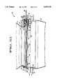
- FIG. 1is a fragmentary front elevational view of the bulk material container embodying the present invention illustrated with a hopper.
- FIG. 2is a horizontal sectional view of the bulk material container shown in FIG. 1 taken along line 2--2 of FIG. 1 with parts thereof broken away to illustrate a centrally located cam assembly and ends of outboard cam assemblies.
- FIG. 3is a horizontal sectional view of the bulk material container shown in FIGS. 1 and 2 taken along line 3--3 of FIG. 1.
- FIG. 4is a vertical sectional view of the bulk material container shown in FIGS. 1-3 taken along line 4--4 of FIG. 2 illustrating a closure plate overlaying the discharge opening of a discharge assembly of the bulk material container and a center cam assembly of the discharge assembly in the cam lock position.
- FIG. 5is a vertical sectional view of the bulk material container shown in FIGS. 1-3 taken along line 4--4 of FIG. 2 illustrating the closure plate partially withdrawn from the discharge assembly of the bulk material container and the center cam assembly of the discharge assembly in the cam unlock position.
- FIG. 6is a vertical sectional view of the bulk material container shown in FIGS. 1-3 taken along line 4--4 of FIG. 2 illustrating the closure plate withdrawn from the discharge assembly of the bulk material container and the center cam assembly of the discharge assembly in the cam unlock position.
- FIG. 7is a vertical sectional view of the bulk material container shown in FIGS. 1-3 taken along line 7--7 of FIG. 2 when the closure plate is fully overlaying the discharge opening of the discharge assembly of the bulk material container and the closure plate is lifted to the seal position.
- FIG. 8is a vertical sectional view of the bulk material container shown in FIGS. 1 and 2 taken along line 7--7 of FIG. 2 when the closure plate is partially withdrawn from the discharge assembly of the bulk material container.
- FIG. 9is a vertical sectional view of the bulk material container shown in FIGS. 1-3 taken along line 7--7 of FIG. 2 when the closure plate has been withdrawn from the discharge assembly of the bulk material container.
- FIG. 10is an end elevational view of the back end of the discharge assembly of the bulk material container shown in FIGS. 1-3.
- FIG. 11is an end elevational view of the discharge assembly of the bulk material container shown in FIGS. 1-3 opposite from the end of the discharge assembly shown in FIG. 10.
- FIG. 12is a vertical sectional view of the bulk material container shown in FIGS. 1-11 taken along line 12--12 of FIG. 2.
- FIG. 13is a vertical sectional view taken along line 4--4 of FIG. 2 to illustrate an integrally formed wiper to provide secondary wiping or scraping of bulk material that remains on or clings to the upper surface of the closure plate and a wiper to provide wiping or scraping of bulk material that remains on or clings to the lower surface of the closure plate.
- FIG. 1Illustrated in FIG. 1 is a fragmentary showing of a bulk material container 20 embodying the present invention.
- the bulk material containercomprises a well-known open bottom bin 21.
- a discharge assembly 25 of the bulk material container 20is disposed at the bottom of the bin 21.
- a suitable hopper 27Disposed below the discharge assembly 25 is a suitable hopper 27.
- the discharge assembly 25defines a rectangular discharge opening 26 (FIG. 3) that communicates with the hopper 27.
- a rectangular, slidable closure plate or door 30(FIG. 2) slides horizontally over a path between a position overlaying the discharge opening 26 to inhibit bulk material from advancing through the opening 26 of the discharge assembly 25 and a position withdrawn from the discharge opening 26 to enable bulk material discharged from the bin 21 to advance through the opening 26 of the discharge assembly 25 into the hopper 27.
- the closure plate 30is made of suitable material, such as steel, aluminum, stainless steel, plastic and the like.
- the discharge assembly 25comprises a generally rectangular housing 31 (FIG. 2) made of suitable material, such as steel.
- the housing 31includes upright walls 32. Joined to the upright walls 32 along the rear and sides thereof are upright walls 34 (FIG. 12). Each of the upright walls 34 at the bottom thereof terminates in a base or horizontal flange 35. At the front end thereof, the upright walls 32 are joined by a horizontal wall 33. Depending from the horizontal wall 33 above the closure plate 30 is an upright wall 36. Another upright wall 37 at the front of the housing 31 is disposed below the closure plate 30.
- a suitable closure seal 40Fixedly positioned against the rectangular shoulder formed by the walls 33 and 34 is a suitable closure seal 40 having a rectangular frame configuration (FIGS. 4-9).
- the closure seal 40is a gasket extrusion made of suitable material, such as ethylene, propylene, diene monomer and the like.
- a rectangular forward plate 41made of suitable material, such as steel, clamps the closure seal 40 to the shoulder formed by the walls 33 and 34 of the discharge assembly 25.
- the forward plate 41is secured to the wall 32 of the frame 25 by suitable means, such as welding or nuts and bolts.
- cam assemblies 45 and 46(FIGS. 1 and 3) of the discharge assembly 25 urge the closure plate 30 into compressive engagement with the closure seal 40.
- cam assemblies 45 and 46comprise, respectively, parallel, elongated eccentric cam rods 50 and 51. The spaced apart cam rods 50 and 51 extend in the direction that the slidable closure plate 30 moves relative to the discharge assembly 25.
- the cam rod 50is journalled for rotation by suitable bushings 52 and 53 located at opposite ends of the cam rod 50.
- the cam rod 51is journalled for rotation by suitable bushings 54 and 55 located at opposite ends of the cam rod 51.
- the bushings 52 and 54are secured to one end of the vertical wall 34 of the housing 31 by suitable means, such as welding, and the bushings 53 and 55 are secured to the opposite end of the vertical wall 34 by suitable means, such as welding.
- suitable meanssuch as welding
- a rear bearingmay be disposed inboard of the rectangular wall 34.
- the rectangular wall 34is suitably apertured to receive the rear end of the associated cam rod.
- the cam rod 50comprises eccentric camming surfaces 56 and 57 and the cam rod 51 comprises eccentric camming surfaces 58 and 59.
- the greater radially extending surfaces of the camming surfaces 56-59serve to urge the closure plate 30 into compressive engagement with the closure seal 40.
- the radially reduced surfaces of the camming surfaces of the camming surfaces 56-59enable the closure plate to be released from compressive engagement with the closure seal 40 when the closure plate 30 is to be moved for opening or closing the opening 26 of the discharge assembly 25. While the closure plate 30 is within the discharge assembly 25 and overlaying the discharge opening 26, it is supported by the cam assemblies 45 and 46.
- the cam rods 50 and 51When withdrawal of the closure plate 30 is desired for material in the bin 21 to be discharged through the opening 26 of the discharge assembly 25 into the hopper 27, the cam rods 50 and 51 are rotated. The rotation of the cam rods 50 and 51 enables the closure plate 30 to be released from compressive engagement with the closure seal 40 while the radially reduced surfaces of the cam rods 50 and 51 support the closure plate 30. Thus, the closure plate 30 is released from compressive engagement with the closure seal 40 to enable the closure plate 30 to be slidably withdrawn from the discharge assembly 25.
- the hopper 27(FIG. 1) is disposed below the discharge assembly 25 to receive bulk material advancing through the opening 26 of the discharge assembly 25 while the closure plate 30 is withdrawn from the discharge assembly 25.
- a suitable, frame-shaped seal 60Between the base 35 and a rectangular frame 59' of the hopper 27 is a suitable, frame-shaped seal 60.
- the seal 60is made of an abrasion resistant elastomer. The seal 60 seals the surface between the discharge assembly 25 and the hopper 27.
- a suitable rectangular, frame-shaped gasket seal 61(FIG. 12).
- the gasket seal 61is made of suitable material, such as neoprene or a spongy-type elastomer. There is a flat surface on all four ends of the discharge assembly 25 (FIG. 12). The back and two sides of the base 35 seat against the elastomer seal 60. The fourth side of the base 35 uses a rectangular bar for sealing between the elastomer seal 60 and the closure plate 30. To take up any irregularities that may develop in sealing the base 35 of the discharge assembly 25 and the flange 62 of the hopper 27, the elastomer seal 61 has been provided. The elastomer seal 60 is applied between the top of the frame 59' and the base 35. The spongy elastomer seal 61 is applied between the bottom of the frame 59' and the flange 62 of the hopper 27 to take up irregularities caused by the usage of the discharge assembly 25 and the hopper 27.
- suitable materialsuch as neoprene or a spongy-type e
- the closure plate 30is moved into the discharge assembly 25 to overlay entirely the discharge opening 26 and to be supported by the reduced radial surfaces of the cam rods 50 and 51. Thereupon, the cam rods 50 and 51 are rotated for the radially greater surfaces of the cam rods 50 and 51 to move the closure plate 30 into compressive engagement with the closure seal 40.
- the closure seal 40forms a bulbous extrusion underlaying a plate 41 (FIG. 7).
- the angular rotation and positioning of the cam rods 50 and 51, respectively,are achieved by means of extension sections 65 and 66, which are formed to provide respective ends for accommodating a square wrench or any suitable angled wrench (FIG. 3). With a suitable square wrench or the like, an operator may rotate the cam rods 50 and 51, respectively, to their desired position.
- Right angular rotational stops 74-77are provided to prevent over travel of the rotation of the cam rods 50 and 51 (FIGS. 3 and 10).
- the rotational stops 74 and 75are welded to the camming rod 50 and prevent over travel by engaging the base 35 of the discharge assembly 25 and the rotational stops 76 and 77 are welded to the cam rod 51 and prevent over travel by engaging the wall 37.
- Pins 74' and 75'are disposed at opposite ends of the cam rod 50 to limit the axial displacement of the cam rod 50.
- pins 76' and 77'are disposed at opposite ends of the cam rod 51 to limit the axial displacement of the cam rod 51.
- the opposite ends of the cam rods 50 and 51may be provided with rotational stops and displacement limiting pins.
- a center cam assembly 80(FIGS. 2-6).
- the center cam assembly 80is disposed in parallel relation to the cam assemblies 45 and 46 midway therebetween.
- the cam assembly 80comprises a cam rod 81 journalled for rotation by a suitable bushing 82.
- the bushing 82is secured to the vertical wall 37 of the discharge assembly 25 by suitable means, such as welding.
- the eccentric cam 85has a greater radially extending camming surface to urge the closure plate 30 into compressive engagement with the closure seal 40.
- the radially reduced camming surface of the cam 85releases the closure plate 30 from compressive engagement with the closure seal 40. While the closure plate 30 is within the discharge assembly 25, it is supported by the cam assembly 80.
- the cam rod 81When withdrawal of the closure plate 30 is desired for material in the bin 21 to be discharged through the opening 26 of the discharge assembly 25 into the hopper 27, the cam rod 81 is rotated in the manner the cam rods 50 and 51 are rotated. The rotation of the cam rod 81 enables the closure plate 30 to be released from compressive engagement with the closure seal 40 in the manner the cam rods 50 and 51 release the closure plate 30 from engagement with the closure seal 40. The closure plate 30 is released from compressive engagement with the closure seal 40 to enable the closure plate 30 to be slidably withdrawn from the discharge assembly 25.
- the closure plate 30is inserted into the discharge assembly 25 to overlay the discharge opening 26 and to be supported by the radially reduced surfaces of the cam rods 50 and 51, as well as by the radially reduced surface of the cam rod 81.
- the cam rods 50 and 51are rotated to move the closure plate 30 into compressive engagement with the closure seal 40.
- the cam rod 81is also rotated to move the closure plate 30 into compressive engagement with the closure seal 40.
- the angular rotation of the rod 81is achieved by means of an extension section, which is formed to accommodate a square wrench or the like (FIG. 11). By a conventional square wrench or the like, an operator may rotate the rod 81 to its desired position.
- a right angular rotational stopwelded to the bushing 82 is a right angular rotational stop, not shown, which is similar to the right angular rotational stops heretofore described for the cam rods 50 and 57.
- the right angular rotational stopengages the wall 37 to prevent over travel of the rotation of the rod 81.
- a pin, not shown, disposed at the end of the cam rod 80limits the axial displacement of the cam rod 81 in a manner heretofore described for the pins 74'-77'.
- the cam assembly 80improves the sealing engagement between the closure seal 40 and the closure plate 30 and reduces the need for a thicker closure plate when a wider closure plate is employed.
- a guide plate 95is secured to the upright wall 34 of the discharge assembly 25 by suitable means, such as welding (FIGS. 7-9 and 12).
- the guide plate 95is located midway between the camming rods 50 and 51 and is disposed to engage the closure plate 30 when the closure plate 30 is approaching the position fully overlaying the opening 26 and while it is supported by the reduced radial surfaces of the camming rods 50 and 51.
- the free end of the guide plate 95is directed downwardly with a gradual slope to serve as a ramp in the guiding of the movement of the closure plate 30.
- wipers 101-103are provided (FIGS. 4 and 5).
- the wipers 101-103remain in contact with the closure plate 30 as the closure plate 30 is withdrawn from the discharge assembly 25 to provide secondary wiping or scraping of the bulk material that remains on or clings to the closure plate 30.
- the hopper 27extends outwardly of the perimeter of the discharge assembly 25 (FIG. 1) to receive bulk material removed from the closure plate 30 as the closure plate 30 is withdrawn from the discharge assembly 25.
- the wipers 101-103not only provide a secondary wiping action, but, also provide a sealing action during the withdrawal of the closure plate 30 from the discharge assembly 25 against leakage of bulk material that would otherwise escape through the aforementioned space.
- the wipers 101-103are made of neoprene.
- the wiper 101has an angular cross-sectional area with a foot section engaging the upper surface of the closure plate 30 while the closure plate 30 overlays the discharge opening 26 in a compressive engagement with the seal 40.
- a leg section of the wiper 101is clamped to a bracket 105 by a screw 104.
- the bracket 105is secured to the horizontal wall 33 by suitable means, such as welding.
- the wiper 102has a right angular cross-sectional area with a foot section engaging the upper surface of the closure plate 30 while the closure plate 30 overlays the discharge opening 26 in compressive engagement with the seal 40.
- a leg section of the wiper 102is clamped by a screw 104 between the bracket 105 and the wall 36.
- the foot sections of the wipers 101 and 102move downwardly and remain in contact with the upper surface of the closure plate 30 maintaining a wiping action therewith.
- the foot sections of the wipers 101 and 102are fully extended in the downward direction.
- the wipers 101 and 102extend over the entire width of the closure plate 30 and are slightly larger in extension than the width of closure plate 30.
- the wiper 103has an angular cross-sectional area with an arm section extended in the upwardly direction and engages the lower surface of the closure plate 30 while the closure plate 30 overlays the discharge opening 26 in compressive engagement with the seal 40 (FIG. 4).
- the body section of the wiper 103is clamped to an upright wall 37 of the discharge assembly 25 by a bracket 107.
- the bracket 107 and the body section of the wiper 103are formed with an opening to receive the bushing 82 of the cam rod assembly 80.
- the bracket 107is secured to the upright wall 37 of the discharge assembly 25 by suitable means, such as nuts and bolts.
- the wiper 103serves to wipe the underside of the closure plate 30.
- the wiper 103springs up when the closure plate 30 is removed to make contact with the wiper 102, thereby closing the opening created by the removal of the closure plate 30 (FIG. 6).
- the arm section of the wiper 103moves downwardly at right angles to the body section of the wiper 103 and firmly engages the lower surface of the closure plate 30 to wipe the same while the closure plate 30 is withdrawn from the discharge assembly 25.
- the arm section of the wiper 103remains at right angles to the body section of the wiper 103 and engages the foot of the wiper 102.
- the wiper 103extends over the entire width of the closure plate 30 and is slightly larger in extension than the width of the closure plate 30.
- Bars 108 and 109are secured to the discharge assembly 25 for supporting the cam rods 50 and 51, respectively, midway between the ends thereof. Should it be desired to remove the discharge assembly 25 for maintenance, a frame-shaped flange, not shown, is welded to the wall 32 of the discharge assembly 25. The frame-shaped flange is bolted to a corresponding frame-shaped flange at the discharge end of the bin 21.
- FIG. 13Illustrated in FIG. 13 is a wiper 120 which is an integration of the wipers 101 and 102 shown in FIGS. 4-6.
- the wiper 120in the preferred embodiment, is a unitary structure. By virtue of the one-piece wiper 120, the installation of wipers for the closure plate has been facilitated.
- the wiper 120is made of neoprene, elastomer, or a suitable rubber material.
- FIG. 13illustrates the closure plate 30" partially withdrawn from the discharge assembly 25" and the center cam assembly 80" of the discharge assembly 25" in the cam unlock position.
- the wiper 120comprises an angular cross-sectional area with a rearward foot section 120a that engages the upper surface of the closure plate 30" while the closure plate 30" overlays the discharge opening 26" and the closure plate 30" is in compressive engagement with the seal 40".
- the wiper 120also comprises an angular cross-sectional area with a forward foot section 120b engaging the upper surface of the closure plate 30" while the closure plate 30" overlays the discharge opening 26" and the closure plate 30" is in compressive engagement with the seal 40".
- the wiper 120comprises a horizontal cross-sectional area with a clamping section 120c. Between the clamping section 120c and the foot 120b, the wiper 120 comprises a cross-sectional area with a vertical leg section 120d. Between the clamping section 120c and the foot section 120a, the wiper 120 comprises a cross-sectional area with an angular leg section 120e.
- a suitable fastenersuch as nut and bolt 121, secures the wiper 120 at the clamping section 120c thereof to a horizontal wall 122.
- the horizontal wall 122is similar in construction and function to the horizontal wall 33 heretofore described.
- the wall 122differs from the wall 33 in that it includes a depending section that engages the leg section 120d of the wiper 120.
- a clamping plate 123is disposed between the head of the fastener 121 and the clamping section 120c of the wiper 120 to secure the wiper 120 to the horizontal wall 122.
- An angular section of the clamp plate 123engages the angular leg section 120e of the wiper 120.
- the foot sections 120a and 120b of the wiper 120move downwardly and remain in contact with the upper surface of the closure plate 30" maintaining a wiper action therewith.
- the foot sections 120a and 120b of the wiper 120are fully extended in the downward direction.
- the wiper 120extends over the entire width of the closure plate 30" and is slightly larger in extension than the width of the closure plate 30".
Landscapes
- Engineering & Computer Science (AREA)
- Mechanical Engineering (AREA)
- Basic Packing Technique (AREA)
Abstract
Description
Claims (28)
Priority Applications (1)
| Application Number | Priority Date | Filing Date | Title |
|---|---|---|---|
| US08/554,455US5697535A (en) | 1995-11-07 | 1995-11-07 | Bulk material container with a sliding cam lock closure plate |
Applications Claiming Priority (1)
| Application Number | Priority Date | Filing Date | Title |
|---|---|---|---|
| US08/554,455US5697535A (en) | 1995-11-07 | 1995-11-07 | Bulk material container with a sliding cam lock closure plate |
Publications (1)
| Publication Number | Publication Date |
|---|---|
| US5697535Atrue US5697535A (en) | 1997-12-16 |
Family
ID=24213394
Family Applications (1)
| Application Number | Title | Priority Date | Filing Date |
|---|---|---|---|
| US08/554,455Expired - LifetimeUS5697535A (en) | 1995-11-07 | 1995-11-07 | Bulk material container with a sliding cam lock closure plate |
Country Status (1)
| Country | Link |
|---|---|
| US (1) | US5697535A (en) |
Cited By (37)
| Publication number | Priority date | Publication date | Assignee | Title |
|---|---|---|---|---|
| US6116228A (en)* | 1997-12-18 | 2000-09-12 | Sanshin Kogyo Kabushiki Kaisha | Control for engine |
| US6123030A (en)* | 1998-04-23 | 2000-09-26 | Miner Enterprises, Inc. | Gate assembly for a railroad hopper car |
| US6328183B1 (en) | 1999-05-11 | 2001-12-11 | Clarence B. Coleman | Mass flow bulk material bin |
| EP0963920A3 (en)* | 1998-06-12 | 2002-08-21 | Autostrade Concessioni E Costruzioni Autostrade S.P.A. | A silo for storing chlorides, including opposed sliding bar extraction devices |
| US6505760B1 (en) | 2001-08-28 | 2003-01-14 | Crustbuster/Speed King | Seed box tote |
| US20070005186A1 (en)* | 2005-07-02 | 2007-01-04 | Syngenta Participations Ag | Apparatus and method for coordinating automated package and bulk dispensing |
| US20080053353A1 (en)* | 2006-09-01 | 2008-03-06 | Norbert Werner | Four box seed box mount with rotary platform and unloading conveyor |
| US20100108711A1 (en)* | 2005-07-02 | 2010-05-06 | Syngenta Participations Ag | Apparatuses and methods for bulk dispensing |
| US20110011893A1 (en)* | 2009-07-17 | 2011-01-20 | James William Cerny | Transportable bulk container with slide gate dispenser |
| US20110101040A1 (en)* | 2009-11-02 | 2011-05-05 | Weissbrod Paul A | Bulk Bag With Gate Valve Assembly |
| CN103274235A (en)* | 2013-06-14 | 2013-09-04 | 鞍钢集团工程技术有限公司 | Mobile dust extraction method and device for screw unloader |
| US20140044507A1 (en)* | 2012-08-07 | 2014-02-13 | Baker Hughes Incorporated | Apparatus and Methods for Assisting in Controlling Material Delivered on a Conveyor |
| CN103803316A (en)* | 2014-02-28 | 2014-05-21 | 中国电力工程顾问集团西南电力设计院 | Sealing cover for pebble coal |
| US9148991B2 (en) | 2013-01-09 | 2015-10-06 | Cnh Industrial America Llc | Gate retention for an inductor box of an agricultural implement |
| US9511929B2 (en) | 2011-12-21 | 2016-12-06 | Oren Technologies, Llc | Proppant storage vessel and assembly thereof |
| USRE46334E1 (en) | 2012-07-23 | 2017-03-07 | Oren Technologies, Llc | Proppant discharge system and a container for use in such a proppant discharge system |
| US9617066B2 (en) | 2011-12-21 | 2017-04-11 | Oren Technologies, Llc | Method of delivering, transporting, and storing proppant for delivery and use at a well site |
| US9624030B2 (en) | 2014-06-13 | 2017-04-18 | Oren Technologies, Llc | Cradle for proppant container having tapered box guides |
| USRE46381E1 (en) | 2012-11-02 | 2017-05-02 | Oren Technologies, Llc | Proppant vessel base |
| US9670752B2 (en) | 2014-09-15 | 2017-06-06 | Oren Technologies, Llc | System and method for delivering proppant to a blender |
| US9676554B2 (en) | 2014-09-15 | 2017-06-13 | Oren Technologies, Llc | System and method for delivering proppant to a blender |
| US9718610B2 (en) | 2012-07-23 | 2017-08-01 | Oren Technologies, Llc | Proppant discharge system having a container and the process for providing proppant to a well site |
| US9758081B2 (en) | 2012-07-23 | 2017-09-12 | Oren Technologies, Llc | Trailer-mounted proppant delivery system |
| US9758082B2 (en) | 2013-04-12 | 2017-09-12 | Proppant Express Solutions, Llc | Intermodal storage and transportation container |
| US9796319B1 (en) | 2013-04-01 | 2017-10-24 | Oren Technologies, Llc | Trailer assembly for transport of containers of proppant material |
| USRE46576E1 (en) | 2013-05-17 | 2017-10-24 | Oren Technologies, Llc | Trailer for proppant containers |
| USRE46590E1 (en) | 2013-05-17 | 2017-10-31 | Oren Technologies, Llc | Train car for proppant containers |
| US9809381B2 (en) | 2012-07-23 | 2017-11-07 | Oren Technologies, Llc | Apparatus for the transport and storage of proppant |
| USRE46613E1 (en) | 2012-11-02 | 2017-11-28 | Oren Technologies, Llc | Proppant vessel |
| US9845210B2 (en) | 2016-01-06 | 2017-12-19 | Oren Technologies, Llc | Conveyor with integrated dust collector system |
| USRE46645E1 (en) | 2013-04-05 | 2017-12-26 | Oren Technologies, Llc | Trailer for proppant containers |
| US9862551B2 (en) | 2012-07-23 | 2018-01-09 | Oren Technologies, Llc | Methods and systems to transfer proppant for fracking with reduced risk of production and release of silica dust at a well site |
| USRE47162E1 (en) | 2012-11-02 | 2018-12-18 | Oren Technologies, Llc | Proppant vessel |
| USD847489S1 (en) | 2012-09-24 | 2019-05-07 | Sandbox Logistics, Llc | Proppant container |
| US10518828B2 (en) | 2016-06-03 | 2019-12-31 | Oren Technologies, Llc | Trailer assembly for transport of containers of proppant material |
| US10618744B2 (en) | 2016-09-07 | 2020-04-14 | Proppant Express Solutions, Llc | Box support frame for use with T-belt conveyor |
| US11873160B1 (en) | 2014-07-24 | 2024-01-16 | Sandbox Enterprises, Llc | Systems and methods for remotely controlling proppant discharge system |
Citations (4)
| Publication number | Priority date | Publication date | Assignee | Title |
|---|---|---|---|---|
| US2750074A (en)* | 1952-12-26 | 1956-06-12 | Entpr Railway Equipment Co | Guiding means for sliding closure of hopper discharge opening |
| US3354918A (en)* | 1966-02-21 | 1967-11-28 | Clarence B Coleman | Bin and unloading stand |
| US3704722A (en)* | 1971-07-12 | 1972-12-05 | Fabricated Metals | Cam and door assembly |
| US4785966A (en)* | 1987-11-05 | 1988-11-22 | Hoover Group, Inc. | Slide gate assembly |
- 1995
- 1995-11-07USUS08/554,455patent/US5697535A/ennot_activeExpired - Lifetime
Patent Citations (4)
| Publication number | Priority date | Publication date | Assignee | Title |
|---|---|---|---|---|
| US2750074A (en)* | 1952-12-26 | 1956-06-12 | Entpr Railway Equipment Co | Guiding means for sliding closure of hopper discharge opening |
| US3354918A (en)* | 1966-02-21 | 1967-11-28 | Clarence B Coleman | Bin and unloading stand |
| US3704722A (en)* | 1971-07-12 | 1972-12-05 | Fabricated Metals | Cam and door assembly |
| US4785966A (en)* | 1987-11-05 | 1988-11-22 | Hoover Group, Inc. | Slide gate assembly |
Cited By (91)
| Publication number | Priority date | Publication date | Assignee | Title |
|---|---|---|---|---|
| US6116228A (en)* | 1997-12-18 | 2000-09-12 | Sanshin Kogyo Kabushiki Kaisha | Control for engine |
| US6123030A (en)* | 1998-04-23 | 2000-09-26 | Miner Enterprises, Inc. | Gate assembly for a railroad hopper car |
| EP0963920A3 (en)* | 1998-06-12 | 2002-08-21 | Autostrade Concessioni E Costruzioni Autostrade S.P.A. | A silo for storing chlorides, including opposed sliding bar extraction devices |
| US6328183B1 (en) | 1999-05-11 | 2001-12-11 | Clarence B. Coleman | Mass flow bulk material bin |
| US6505760B1 (en) | 2001-08-28 | 2003-01-14 | Crustbuster/Speed King | Seed box tote |
| US20100108711A1 (en)* | 2005-07-02 | 2010-05-06 | Syngenta Participations Ag | Apparatuses and methods for bulk dispensing |
| US7640075B2 (en)* | 2005-07-02 | 2009-12-29 | Syngenta Participations Ag | Apparatus and method for coordinating automated package and bulk dispensing |
| US20100017021A1 (en)* | 2005-07-02 | 2010-01-21 | Syngenta Participations Ag | Apparatus and method for coordinating automated package and bulk dispensing |
| US8387824B2 (en) | 2005-07-02 | 2013-03-05 | Syngenta Participations Ag | Apparatuses and methods for bulk dispensing |
| US20070005186A1 (en)* | 2005-07-02 | 2007-01-04 | Syngenta Participations Ag | Apparatus and method for coordinating automated package and bulk dispensing |
| US8442675B2 (en) | 2005-07-02 | 2013-05-14 | Syngenta Participations Ag | Apparatus and method for coordinating automated package and bulk dispensing |
| US20080053353A1 (en)* | 2006-09-01 | 2008-03-06 | Norbert Werner | Four box seed box mount with rotary platform and unloading conveyor |
| US20110011893A1 (en)* | 2009-07-17 | 2011-01-20 | James William Cerny | Transportable bulk container with slide gate dispenser |
| US8371476B2 (en) | 2009-11-02 | 2013-02-12 | Lincoln Global, Inc. | Bulk bag with gate valve assembly |
| US20110101040A1 (en)* | 2009-11-02 | 2011-05-05 | Weissbrod Paul A | Bulk Bag With Gate Valve Assembly |
| US10538381B2 (en) | 2011-09-23 | 2020-01-21 | Sandbox Logistics, Llc | Systems and methods for bulk material storage and/or transport |
| US10562702B2 (en) | 2011-09-23 | 2020-02-18 | Sandbox Logistics, Llc | Systems and methods for bulk material storage and/or transport |
| US10703587B2 (en) | 2011-12-21 | 2020-07-07 | Oren Technologies, Llc | Method of delivering, transporting, and storing proppant for delivery and use at a well site |
| US9932181B2 (en) | 2011-12-21 | 2018-04-03 | Oren Technologies, Llc | Method of delivering, transporting, and storing proppant for delivery and use at a well site |
| US9914602B2 (en) | 2011-12-21 | 2018-03-13 | Oren Technologies, Llc | Methods of storing and moving proppant at location adjacent rail line |
| US9682815B2 (en) | 2011-12-21 | 2017-06-20 | Oren Technologies, Llc | Methods of storing and moving proppant at location adjacent rail line |
| US9511929B2 (en) | 2011-12-21 | 2016-12-06 | Oren Technologies, Llc | Proppant storage vessel and assembly thereof |
| US9527664B2 (en) | 2011-12-21 | 2016-12-27 | Oren Technologies, Llc | Proppant storage vessel and assembly thereof |
| US9643774B2 (en) | 2011-12-21 | 2017-05-09 | Oren Technologies, Llc | Proppant storage vessel and assembly thereof |
| US9617066B2 (en) | 2011-12-21 | 2017-04-11 | Oren Technologies, Llc | Method of delivering, transporting, and storing proppant for delivery and use at a well site |
| US10814767B2 (en) | 2012-07-23 | 2020-10-27 | Oren Technologies, Llc | Trailer-mounted proppant delivery system |
| US10661980B2 (en) | 2012-07-23 | 2020-05-26 | Oren Technologies, Llc | Method of delivering, storing, unloading, and using proppant at a well site |
| USRE46334E1 (en) | 2012-07-23 | 2017-03-07 | Oren Technologies, Llc | Proppant discharge system and a container for use in such a proppant discharge system |
| US9656799B2 (en) | 2012-07-23 | 2017-05-23 | Oren Technologies, Llc | Method of delivering, storing, unloading, and using proppant at a well site |
| US10662006B2 (en) | 2012-07-23 | 2020-05-26 | Oren Technologies, Llc | Proppant discharge system having a container and the process for providing proppant to a well site |
| US9669993B2 (en) | 2012-07-23 | 2017-06-06 | Oren Technologies, Llc | Proppant discharge system and a container for use in such a proppant discharge system |
| US10661981B2 (en) | 2012-07-23 | 2020-05-26 | Oren Technologies, Llc | Proppant discharge system and a container for use in such a proppant discharge system |
| US9969564B2 (en) | 2012-07-23 | 2018-05-15 | Oren Technologies, Llc | Methods and systems to transfer proppant for fracking with reduced risk of production and release of silica dust at a well site |
| US9694970B2 (en) | 2012-07-23 | 2017-07-04 | Oren Technologies, Llc | Proppant discharge system and a container for use in such a proppant discharge system |
| US9701463B2 (en) | 2012-07-23 | 2017-07-11 | Oren Technologies, Llc | Method of delivering, storing, unloading, and using proppant at a well site |
| US9718610B2 (en) | 2012-07-23 | 2017-08-01 | Oren Technologies, Llc | Proppant discharge system having a container and the process for providing proppant to a well site |
| US9718609B2 (en) | 2012-07-23 | 2017-08-01 | Oren Technologies, Llc | Proppant discharge system and a container for use in such a proppant discharge system |
| US9725233B2 (en) | 2012-07-23 | 2017-08-08 | Oren Technologies, Llc | Proppant discharge system and a container for use in such a proppant discharge system |
| US9725234B2 (en) | 2012-07-23 | 2017-08-08 | Oren Technologies, Llc | Proppant discharge system and a container for use in such a proppant discharge system |
| US9738439B2 (en) | 2012-07-23 | 2017-08-22 | Oren Technologies, Llc | Proppant discharge system and a container for use in such a proppant discharge system |
| US10239436B2 (en) | 2012-07-23 | 2019-03-26 | Oren Technologies, Llc | Trailer-mounted proppant delivery system |
| US9758081B2 (en) | 2012-07-23 | 2017-09-12 | Oren Technologies, Llc | Trailer-mounted proppant delivery system |
| US9862551B2 (en) | 2012-07-23 | 2018-01-09 | Oren Technologies, Llc | Methods and systems to transfer proppant for fracking with reduced risk of production and release of silica dust at a well site |
| US9771224B2 (en) | 2012-07-23 | 2017-09-26 | Oren Technologies, Llc | Support apparatus for moving proppant from a container in a proppant discharge system |
| US10464741B2 (en) | 2012-07-23 | 2019-11-05 | Oren Technologies, Llc | Proppant discharge system and a container for use in such a proppant discharge system |
| US10569953B2 (en) | 2012-07-23 | 2020-02-25 | Oren Technologies, Llc | Proppant discharge system and a container for use in such a proppant discharge system |
| US10745194B2 (en) | 2012-07-23 | 2020-08-18 | Oren Technologies, Llc | Cradle for proppant container having tapered box guides and associated methods |
| US9809381B2 (en) | 2012-07-23 | 2017-11-07 | Oren Technologies, Llc | Apparatus for the transport and storage of proppant |
| US9815620B2 (en) | 2012-07-23 | 2017-11-14 | Oren Technologies, Llc | Proppant discharge system and a container for use in such a proppant discharge system |
| US10787312B2 (en) | 2012-07-23 | 2020-09-29 | Oren Technologies, Llc | Apparatus for the transport and storage of proppant |
| US9834373B2 (en) | 2012-07-23 | 2017-12-05 | Oren Technologies, Llc | Proppant discharge system and a container for use in such a proppant discharge system |
| US20140044507A1 (en)* | 2012-08-07 | 2014-02-13 | Baker Hughes Incorporated | Apparatus and Methods for Assisting in Controlling Material Delivered on a Conveyor |
| US9260253B2 (en)* | 2012-08-07 | 2016-02-16 | Baker Hughes Incorporated | Apparatus and methods for assisting in controlling material discharged from a conveyor |
| USD847489S1 (en) | 2012-09-24 | 2019-05-07 | Sandbox Logistics, Llc | Proppant container |
| USRE46613E1 (en) | 2012-11-02 | 2017-11-28 | Oren Technologies, Llc | Proppant vessel |
| USRE46381E1 (en) | 2012-11-02 | 2017-05-02 | Oren Technologies, Llc | Proppant vessel base |
| USRE46531E1 (en) | 2012-11-02 | 2017-09-05 | Oren Technologies, Llc | Proppant vessel base |
| USRE47162E1 (en) | 2012-11-02 | 2018-12-18 | Oren Technologies, Llc | Proppant vessel |
| US9820428B2 (en) | 2013-01-09 | 2017-11-21 | Cnh Industrial America Llc | Gate retention for an inductor box of an agricultural implement |
| US9148991B2 (en) | 2013-01-09 | 2015-10-06 | Cnh Industrial America Llc | Gate retention for an inductor box of an agricultural implement |
| US9796319B1 (en) | 2013-04-01 | 2017-10-24 | Oren Technologies, Llc | Trailer assembly for transport of containers of proppant material |
| US10059246B1 (en) | 2013-04-01 | 2018-08-28 | Oren Technologies, Llc | Trailer assembly for transport of containers of proppant material |
| USRE46645E1 (en) | 2013-04-05 | 2017-12-26 | Oren Technologies, Llc | Trailer for proppant containers |
| US10118529B2 (en) | 2013-04-12 | 2018-11-06 | Proppant Express Solutions, Llc | Intermodal storage and transportation container |
| US9758082B2 (en) | 2013-04-12 | 2017-09-12 | Proppant Express Solutions, Llc | Intermodal storage and transportation container |
| USRE46576E1 (en) | 2013-05-17 | 2017-10-24 | Oren Technologies, Llc | Trailer for proppant containers |
| USRE46590E1 (en) | 2013-05-17 | 2017-10-31 | Oren Technologies, Llc | Train car for proppant containers |
| CN103274235A (en)* | 2013-06-14 | 2013-09-04 | 鞍钢集团工程技术有限公司 | Mobile dust extraction method and device for screw unloader |
| CN103274235B (en)* | 2013-06-14 | 2015-04-29 | 鞍钢集团工程技术有限公司 | Mobile dust extraction method and device for screw unloader |
| CN103803316A (en)* | 2014-02-28 | 2014-05-21 | 中国电力工程顾问集团西南电力设计院 | Sealing cover for pebble coal |
| US9840366B2 (en) | 2014-06-13 | 2017-12-12 | Oren Technologies, Llc | Cradle for proppant container having tapered box guides |
| US9624030B2 (en) | 2014-06-13 | 2017-04-18 | Oren Technologies, Llc | Cradle for proppant container having tapered box guides |
| US11873160B1 (en) | 2014-07-24 | 2024-01-16 | Sandbox Enterprises, Llc | Systems and methods for remotely controlling proppant discharge system |
| US9670752B2 (en) | 2014-09-15 | 2017-06-06 | Oren Technologies, Llc | System and method for delivering proppant to a blender |
| US9988215B2 (en) | 2014-09-15 | 2018-06-05 | Oren Technologies, Llc | System and method for delivering proppant to a blender |
| US9676554B2 (en) | 2014-09-15 | 2017-06-13 | Oren Technologies, Llc | System and method for delivering proppant to a blender |
| US10399789B2 (en) | 2014-09-15 | 2019-09-03 | Oren Technologies, Llc | System and method for delivering proppant to a blender |
| US10179703B2 (en) | 2014-09-15 | 2019-01-15 | Oren Technologies, Llc | System and method for delivering proppant to a blender |
| US9919882B2 (en) | 2016-01-06 | 2018-03-20 | Oren Technologies, Llc | Conveyor with integrated dust collector system |
| US9902576B1 (en)* | 2016-01-06 | 2018-02-27 | Oren Technologies, Llc | Conveyor with integrated dust collector system |
| US9932183B2 (en) | 2016-01-06 | 2018-04-03 | Oren Technologies, Llc | Conveyor with integrated dust collector system |
| US10676296B2 (en) | 2016-01-06 | 2020-06-09 | Oren Technologies, Llc | Conveyor with integrated dust collector system |
| US10065816B2 (en) | 2016-01-06 | 2018-09-04 | Oren Technologies, Llc | Conveyor with integrated dust collector system |
| US10035668B2 (en) | 2016-01-06 | 2018-07-31 | Oren Technologies, Llc | Conveyor with integrated dust collector system |
| US9845210B2 (en) | 2016-01-06 | 2017-12-19 | Oren Technologies, Llc | Conveyor with integrated dust collector system |
| US9868598B2 (en) | 2016-01-06 | 2018-01-16 | Oren Technologies, Llc | Conveyor with integrated dust collector system |
| US10926967B2 (en) | 2016-01-06 | 2021-02-23 | Sandbox Enterprises, Llc | Conveyor with integrated dust collector system |
| US11414282B2 (en) | 2016-01-06 | 2022-08-16 | Sandbox Enterprises, Llc | System for conveying proppant to a fracking site hopper |
| US9963308B2 (en) | 2016-01-06 | 2018-05-08 | Oren Technologies, Llc | Conveyor with integrated dust collector system |
| US10518828B2 (en) | 2016-06-03 | 2019-12-31 | Oren Technologies, Llc | Trailer assembly for transport of containers of proppant material |
| US10618744B2 (en) | 2016-09-07 | 2020-04-14 | Proppant Express Solutions, Llc | Box support frame for use with T-belt conveyor |
Similar Documents
| Publication | Publication Date | Title |
|---|---|---|
| US5697535A (en) | Bulk material container with a sliding cam lock closure plate | |
| US4475672A (en) | Hopper discharge device | |
| US5336027A (en) | Vehicle for carrying coiled rolls | |
| US6070736A (en) | Sealing mechanism and method for screening machines | |
| US4785966A (en) | Slide gate assembly | |
| US4570277A (en) | Leveler assembly | |
| US5195285A (en) | Deformable sealing device for a gap between a wall opening of a building wall and a back wall of a vehicle | |
| US3415204A (en) | Hopper gate sealing means | |
| EP2848580B1 (en) | Device for dosing a product into a container | |
| DE1431673A1 (en) | Device for emptying a tilting container that contains bulk goods | |
| US4940132A (en) | Seals for reciprocating conveyor floor members | |
| US4530483A (en) | Side guide for cargo loading system | |
| US5507235A (en) | Gravity outlet | |
| AU2009238310B2 (en) | An improved hopper discharge door system | |
| US4133576A (en) | Hatch for vehicle roofs | |
| KR102106132B1 (en) | the loading and unloading transpire system for arkshell carrier | |
| US20160286823A1 (en) | Canopy and associated seal arrangement for mixer | |
| DE69211321T2 (en) | Portable waste bin with improved inlet valve arrangement | |
| DE3242640C2 (en) | ||
| US6505727B2 (en) | Slide gate for a conveyor system | |
| US4528913A (en) | Gravity outlet sliding gate seal | |
| US4000703A (en) | Trough hatch locking device | |
| FR2516856A1 (en) | DEVICE FOR UNLOADING AN INJECTION MOLDING PRESS | |
| DE4215256A1 (en) | Seal for gap between frame and door or flap - is used on goods vehicle and has hollow hose strip inflatable from compressed air source | |
| WO1993001968A1 (en) | A bulkhead door arrangement |
Legal Events
| Date | Code | Title | Description |
|---|---|---|---|
| AS | Assignment | Owner name:FABRICATED METALS, INC., CALIFORNIA Free format text:ASSIGNMENT OF ASSIGNORS INTEREST;ASSIGNOR:COLEMAN, CLARENCE B.;REEL/FRAME:007742/0096 Effective date:19951102 | |
| STCF | Information on status: patent grant | Free format text:PATENTED CASE | |
| AS | Assignment | Owner name:CSI FABRICATED METALS, INC., PENNSYLVANIA Free format text:ASSIGNMENT OF ASSIGNORS INTEREST;ASSIGNOR:FABRICATED METALS, INC.;REEL/FRAME:011648/0689 Effective date:20010322 | |
| FPAY | Fee payment | Year of fee payment:4 | |
| AS | Assignment | Owner name:CSI FABRICATED METAL BINS, INC., PENNSYLVANIA Free format text:ASSIGNMENT OF ASSIGNORS INTEREST;ASSIGNOR:FABRICATED METALS, INC.;REEL/FRAME:016283/0341 Effective date:20040707 | |
| FPAY | Fee payment | Year of fee payment:8 | |
| AS | Assignment | Owner name:CSI INDUSTRIES INC., PENNSYLVANIA Free format text:ASSIGNMENT OF ASSIGNORS INTEREST;ASSIGNOR:CSI FABRICATED METAL BINS INC.;REEL/FRAME:018109/0868 Effective date:20060331 | |
| FPAY | Fee payment | Year of fee payment:12 |