US5697248A - Liquid level sensor - Google Patents
Liquid level sensorDownload PDFInfo
- Publication number
- US5697248A US5697248AUS08/185,836US18583694AUS5697248AUS 5697248 AUS5697248 AUS 5697248AUS 18583694 AUS18583694 AUS 18583694AUS 5697248 AUS5697248 AUS 5697248A
- Authority
- US
- United States
- Prior art keywords
- transmitter
- receiver
- liquid
- segments
- transmission path
- Prior art date
- Legal status (The legal status is an assumption and is not a legal conclusion. Google has not performed a legal analysis and makes no representation as to the accuracy of the status listed.)
- Expired - Fee Related
Links
Images


Classifications
- G—PHYSICS
- G01—MEASURING; TESTING
- G01F—MEASURING VOLUME, VOLUME FLOW, MASS FLOW OR LIQUID LEVEL; METERING BY VOLUME
- G01F23/00—Indicating or measuring liquid level or level of fluent solid material, e.g. indicating in terms of volume or indicating by means of an alarm
- G01F23/22—Indicating or measuring liquid level or level of fluent solid material, e.g. indicating in terms of volume or indicating by means of an alarm by measuring physical variables, other than linear dimensions, pressure or weight, dependent on the level to be measured, e.g. by difference of heat transfer of steam or water
- G01F23/28—Indicating or measuring liquid level or level of fluent solid material, e.g. indicating in terms of volume or indicating by means of an alarm by measuring physical variables, other than linear dimensions, pressure or weight, dependent on the level to be measured, e.g. by difference of heat transfer of steam or water by measuring the variations of parameters of electromagnetic or acoustic waves applied directly to the liquid or fluent solid material
- G01F23/296—Acoustic waves
- G01F23/2961—Acoustic waves for discrete levels
- G—PHYSICS
- G01—MEASURING; TESTING
- G01F—MEASURING VOLUME, VOLUME FLOW, MASS FLOW OR LIQUID LEVEL; METERING BY VOLUME
- G01F23/00—Indicating or measuring liquid level or level of fluent solid material, e.g. indicating in terms of volume or indicating by means of an alarm
- G01F23/22—Indicating or measuring liquid level or level of fluent solid material, e.g. indicating in terms of volume or indicating by means of an alarm by measuring physical variables, other than linear dimensions, pressure or weight, dependent on the level to be measured, e.g. by difference of heat transfer of steam or water
- G01F23/28—Indicating or measuring liquid level or level of fluent solid material, e.g. indicating in terms of volume or indicating by means of an alarm by measuring physical variables, other than linear dimensions, pressure or weight, dependent on the level to be measured, e.g. by difference of heat transfer of steam or water by measuring the variations of parameters of electromagnetic or acoustic waves applied directly to the liquid or fluent solid material
- G01F23/296—Acoustic waves
- G01F23/2962—Measuring transit time of reflected waves
- G—PHYSICS
- G01—MEASURING; TESTING
- G01F—MEASURING VOLUME, VOLUME FLOW, MASS FLOW OR LIQUID LEVEL; METERING BY VOLUME
- G01F23/00—Indicating or measuring liquid level or level of fluent solid material, e.g. indicating in terms of volume or indicating by means of an alarm
- G01F23/22—Indicating or measuring liquid level or level of fluent solid material, e.g. indicating in terms of volume or indicating by means of an alarm by measuring physical variables, other than linear dimensions, pressure or weight, dependent on the level to be measured, e.g. by difference of heat transfer of steam or water
- G01F23/28—Indicating or measuring liquid level or level of fluent solid material, e.g. indicating in terms of volume or indicating by means of an alarm by measuring physical variables, other than linear dimensions, pressure or weight, dependent on the level to be measured, e.g. by difference of heat transfer of steam or water by measuring the variations of parameters of electromagnetic or acoustic waves applied directly to the liquid or fluent solid material
- G01F23/296—Acoustic waves
- G01F23/2968—Transducers specially adapted for acoustic level indicators
Definitions
- This inventionis relates to a device for sensing the level of liquid within a container and, particularly, to a device in the form of a solid state arrangement having no moving parts and readily adaptable to deal with containers of non-uniform shape.
- Certain forms of the present inventionprovide a device which fulfils this function by providing a plurality of independent ultrasonic transducers disposed in such a way that the presence or absence of liquid between a given transmitter element and a given receiver element can readily be detected.
- FIG. 1is a schematic cross-sectional view of a liquid level sensor forming a first embodiment of the invention
- FIG. 2ais a cross-sectional side view of a second embodiment of sensor
- FIG. 2bis a sectional plan view of the sensor of FIG. 2a;
- FIG. 3is a graph illustrating the operation of one aspect of the sensor of FIG.2;
- FIG. 4ashows a pcb track layout used in a third embodiment
- FIG. 4bis an enlarged view of part of FIG. 4a;
- FIG. 4cis a cross-sectional side view of an embodiment using the pcb of FIG. 4a;
- FIG. 5illustrates a two-segment receiver of a second embodiment, the receiver having equal but opposite receiver segments
- FIG. 6shows the ratiometric output of the receiver of FIG. 5
- FIGS. 7a and 7billustrate a two-segment receiver similar to that of FIG. 5 but having segments defined by a non-uniform curve
- FIG. 8shows signal strengths from the segments of the receiver of FIG. 7a
- FIG. 9shows the ratiometric output of the receiver of FIG. 7a and
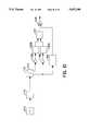
- FIG. 10illustrates one form of electronics suitable for use with the receiver of FIG. 7a.
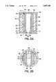
- a sensorcomprises a pair of ultrasonic transducers 10, 12 mounted at a fixed separation S on either side of a container holding liquid 14, or directly immersed in liquid.
- One transducer 10forms a transmitter and comprises a plurality of independent conductive (i.e., transmitter) segments 16 each of which may be individually addressed by associated drive electronics (not shown).
- the other transducer 12forms a receiver and comprises a single conductive element 18 having a sufficient geometric extent to receive ultrasonic acoustic signals generated by activation of any of the transmitter segments 16.
- the device of this embodimentis used in the following manner.
- An electrical stimulusis applied to each transmitter segment 16 in turn.
- the time delay between application of the stimulus and reception of the resulting acoustic signalmay be calculated or measured for the specific liquid involved, and is governed by the speed of sound in the medium and by the physical separations of the transmitter 10 and receiver 12. If a signal has not been detected by the receiver 12 within the appropriate time window, then it can be concluded that the liquid has not reached the height of the given transmitter segment.
- One suitable piezoelectric materialis suitably processed poly(vinylidene fluoride) (PVDF or PVF 2 ); another is vinylidene fluoride-trifluoroethylene (VF 2 VF 3 ) copolymer.
- Suitable patterning of the signal electrodesmay be accomplished by the normal means, i.e. by vacuum depositing or sputtering the metallic electrode material through a mask, or by etching a continuous metallic layer to obtain the required pattern.
- a continuous piezoelectric matrixmay be laid down upon a patterned substrate.
- the patterned substratemay consist of printed circuit board (p.c.b.) 24 whereby etched lands of copper may form the segments 16.
- p.c.b. materialas the backing layer
- double-sided beardmay be used. Plated-through holes 26 then allow interconnection and wiring of all segments to be accomplished on the rear surface connection pads 28, leaving the front surface unhindered for application of the piezoelectric layer 20.
- a further benefit of using double-sided circuit boardis that the rear side copper may be left substantially intact as shown at 30, and connected to ground potential, where the receiver design is considered. This affords good electrical shielding of the receiver element, so reducing the extent of the electromagnetically-coupled signal from the transmitter. It is of great importance that this "cross-talk" is minimised, to avoid saturation of the receiver circuitry, or false triggering, prior to the arrival of the true acoustic signal.
- the piezoelectric polymer matrix 20may be applied in two ways.
- One methodis to use a sheet of said polymer, with metallization applied to the outer surface only.
- the inner surfacemay be bonded to the patterned p.c.b. material 24 by a number of adhesive methods, for instance, using epoxy resin.
- the adhesive layer so introducedis normally thin in relation to the thickness of the piezoelectric polymer employed.
- the electrical signal applied to or generated by such an assemblywill be capacitively coupled through the additional dielectric layer formed by the adhesive.
- the piezoelectric material usedis the VF 2 VF 3 copolymer mentioned above.
- This materialmay initially consist of a solution which can be applied by casting or spin-casting directly on the p.c.b. material. After evaporation of the solvent, the resulting layer must then be polarized as part of the process whereby it is rendered piezoelectric: this polarization may be preferably applied only at the regions of the signal electrodes.
- this polarizationmay be preferably applied only at the regions of the signal electrodes.
- the polymer material lying above each patterned electrodemay be considered to be piezolectric, while the material between each electrode may be considered inert. Suitable polarization procedures are well known to those in the art.
- the systemis capable of a self-check function. It is possible to drive the piezoelectric transducers at such a frequency that the acoustic signal may be transmitted successfully through air as well as liquid, although with different transmission delay. In this case, the operation of all segments may be verified periodically.
- the electrical signal applied to the transmitterhas substantial energy content in the frequency range 200 kHz to 5 MHz.
- the time duration of the applied signalmay vary widely, between a very fast spike and a step function of indeterminate length.
- a rectangular pulse of 0.1 to 10 ⁇ sis preferred, especially about 0.2 ⁇ s.
- the spacing S between the transmitter 10 and the receiver 12may suitably be between 1 mm and 25 mm.
- the piezoelectric films 20may suitably have a thickness of 0.1 ⁇ m to 500 ⁇ m; it his been found however that the electrical behaviour is substantially independent of film thickness and any available film thickness will produce a usable result.
- a possible modification of the foregoing embodiment of the present inventionwould use a receiver transducer of the same construction as the transmitter; in other words, the system would comprise two identical linear arrays, with the electrical stimulus being applied to each transmitter segment in turn, while the corresponding receiver segment is monitored for the arrival or non-arrival of the acoustic signal.
- This embodimentoffers greater electrical signal strength of the detected receiver signal since, in effect, the entire area of each receiver segment may be excited by the incidence of the acoustic wave, but this method increases the complexity of the associated electronic circuitry.
- each transmitter segment 16be small, to allow a large number of segments within the range of the sensor, and that the spacing between each segment be either regular or varied, according to the geometry of the container.
- a further optional feature of the inventionis that the propagation delay of the acoustic signal from transmitter to receiver may be measured, and so knowledge obtained regarding the composition of the liquid.
- An example of this applicationwould be when a possibility exists of contamination of gasoline with water, where the water forms a layer at the bottom of the container.
- appropriate control signalscan be generated to detect abnormal early reception of the acoustic signal.
- the speed informationcan be examined for each segment in turn, and thus a profile of the characteristics of the liquid column can be developed.
- each levelmay have a corresponding weighting factor applied from a look-up table held in a ROM or the like, to provide a user output in terms of liquid volume rather than liquid depth. This is particularly useful in monitoring the contents of tanks having irregular stapes.
- FIG. 2illustrates a modified version of the embodiment of FIG. 1.
- the transducers 10, 12comprise pcb's 24 carrying piezo films 20. These are mounted within a housing in the form of an extruded polymer tube 32 which is placed within the tank (not shown).
- the electronic components 34which may suitably be surface mount devices, are mounted directly on the conductor patterns on the rear side of the transmitter pcb 24.
- the cavities formed between the tube 32 and the pcb's 24are filled with an encapsulation material 36 such as epoxy resin.
- the piezo films 20are less prone to attack, but the metallized surfaces may be chemically attacked or corroded.
- Protective coatings 38are therefore provided.
- the coatings 38may be conformal coatings of suitable protective material, for example epoxy resin, applied in any suitable way such as dipping, brushing or spraying.
- the coatings 38may be provided by bonding a thin sheet of inert, stable polymer onto the front face of the transducer in such a way that, as shown in FIG. 2, the polymer sheet itself acts to locate the assembly within the tube 32.
- Said suitable inert polymersmay be, for example only, polyethylene (UHMW or HDPE) or polyvinylidene fluoride (PVDF, Kynar), or others.
- extruded tube 32(which may be circular or rectangular in section) allows the possibility of forming it with mounting grooves or ribs for the pcb's and other assembly aids.
- the housingis substantially closed by end caps 40, 42 on the tube 32.
- the lower end cap 40is provided with a restricted aperture 44 for entry and exit of the liquid, and an air bleed aperture 46 is provided in the upper end cap 42.
- Thisprovides a damping effect on the rate of liquid level change and, especially in conjunction with a narrow spacing between the transducers, greatly limits the effects of liquid surging or "slosh".
- the internal cavitycan be further provided with baffles (not shown).
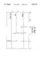
- a further optional feature illustrated in FIG. 2is a self-test capability.
- a block 50 of solid materialis disposed between the transducers 10, 12 in such a manner that it links part of each transmitter segment directly to the receiver. With this arrangement, the transmission of a pulse from a transmitter segment causes a pulse to be received via the block 50 before any transmission through the liquid.
- FIG. 3in which (a) represents a short, unipolar transmitted pulse, (b) represents the receiver signal in air, with a distinct pulse being received only via the solid block, and (c) represents the receiver signal in water, the second distinct pulse being the transmission via the water.
- Suitable materials for the block 50are polymers such as high-density polyethylene and polymethylmethacrylate. The example of FIG. 3 was measured with a PMMA spacer of 14.6 mm thickness covering 50% of each transmitter segment.
- This featurecan be used to give warning of a system failure, since in normal operation a pulse will be received a given time after every transmitted pulse.
- the spaced transmitter and receiver transducersare replaced by a single transmitter/receiver assembly operating in pulse-echo mode in conjunction with a passive reflector. It is known in other applications of ultrasonics to use pulse-echo techniques. Conventionally, this requires a receiver to be switched at appropriate times to avoid it detecting the transmitted pulse. In the present application with a short transmission path and a number of transmitters, such switching would be possible but would be complex and expensive to implement.
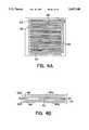
- FIG. 4aillustrates a prototype transmitter/receiver assembly incorporating six transmitter segments and a common receiver. As in the above embodiments, the assembly makes use of piezo film secured to a pcb.
- FIG. 4ashows the track layout of the pcb, while FIG. 4b shows part of the track layout in greater detail.
- Each transmitter segment 60is formed by a pair of spaced strips 60a, 60b interleaved by a receiver strip 62.
- the receiver stripsare connected together at 64, while each transmitter segment 60 is connected independently to the associated circuitry by a via 66.
- the overall effectis therefore a series of transmitter segments, and a common receiver segment of large area, but comprising an array of interdigital parts.
- the transmitter segments 60are fired individually in the same manner as in the embodiments of FIGS. 1 and 2, and the same receiver processing is used. Instead of a separate pcb, all that is required is a passive reflector (which could be a separate item, or simply the wall of the tank) at a suitable spacing to give sufficient time delay for any directly coupled crosstalk to subside.
- a continuous ground conductor 68is preferably interleaved between them. It is also preferable to interlay a plane of cooper which is substantially unbroken (except for the vias such as 66 carrying signals through this layer to the component side) which serves as a ground plane.
- the receiver strips 62will see a ground plane to the rear (the mid-board copper), to each side (the conductor 68), and also to the front (the piezo film metallization).
- FIG. 4cshows an embodiment of the invention, in which the sensor of FIG. 2 is modified to make use of the pcb of FIGS. 4a and 4b.
- the pcb 24operates in conjunction with a passive reflective surface 47.
- the sensoris otherwise similar to that of FIG. 2 with like references.
- FIGS. 5 to 10consider first a simple ultrasonic transmitter/receiver system where both transducers are plain, rectangular elements, formed by bonding piezoelectric polymer film onto a suitable substrate e.g. printed circuit board material. As the liquid level between the two plates rises, the acoustic coupling of signal will increase in a linear fashion from zero to a maximum value.
- xrepresents the varying immersion depth describes a curve which splits the rectangular receiver area into two portions, each of equal area, such that the ratio of their areas immersed will change from zero to unity in a linear function of depth.
- the signal output from each receiveris found to be directly proportional to the "area function" g(x).
- FIG. 7a and 7b(referred to collectively as FIG. 7) illustrate suitable electrode patterns, the transmitter electrode being shown at 110 and the split receiver electrodes at 112 and 114.
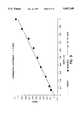
- FIGS. 8 and 9show graphically the absolute signal strength and signal strength ratio produced experimentally by the transmitter and receiver of FIG. 7. The ratiometric output shows good approximation to a linear response.
- a small additional receiver segment extending from zero to critical depthmay be patterned, such that the division is only performed if this segment is "fully on”.
- FIG. 10One example of the electronics required for a basic measurement system using the sensor of FIG. 7 is shown in FIG. 10.
- the transmitter 10is driven by an oscillator 46 which may supply a constant or burst signal at suitable frequency, typically 0.5-1.5 MHz, and moderate amplitude, typically 1-20 volts peak-to-peak.
- the outputs of the receiver segments 112, 114are fed via dual, matched gain stages 118A and 118B to dual peek detectors 120A, 120B to give absolute signal strength inputs to analog divider circuit 122.
- the peak detectors 120may have short hold times, or alternatively RMS-to-DC converters may be used.
- the analog divider 122may suitably be AD532, AD534 or AD538.
- a threshold detector 124operates gate 126 to blank the output when the received signal is close to zero.
- the curve defining each receiver segmentmay be adjusted to compensate for non-uniformity of the container cross-section, such that the relationship between ratiometric signal output and liquid volume remains constant.
Landscapes
- Physics & Mathematics (AREA)
- Electromagnetism (AREA)
- Thermal Sciences (AREA)
- Fluid Mechanics (AREA)
- General Physics & Mathematics (AREA)
- Acoustics & Sound (AREA)
- Measurement Of Levels Of Liquids Or Fluent Solid Materials (AREA)
Abstract
Description
f(x)=(2x/(1+x))-(x.sup.2 /(1+x).sup.2)
g(x)=f(x)dx=x.sup.2 /(1+x)
Claims (25)
Applications Claiming Priority (5)
| Application Number | Priority Date | Filing Date | Title |
|---|---|---|---|
| GB9116092 | 1991-07-25 | ||
| GB919116092AGB9116092D0 (en) | 1991-07-25 | 1991-07-25 | Liquid level sensor |
| GB9201740 | 1992-01-28 | ||
| GB929201740AGB9201740D0 (en) | 1992-01-28 | 1992-01-28 | Liquid level sensor |
| PCT/GB1992/001393WO1993002340A1 (en) | 1991-07-25 | 1992-07-27 | Liquid level sensor |
Publications (1)
| Publication Number | Publication Date |
|---|---|
| US5697248Atrue US5697248A (en) | 1997-12-16 |
Family
ID=26299287
Family Applications (1)
| Application Number | Title | Priority Date | Filing Date |
|---|---|---|---|
| US08/185,836Expired - Fee RelatedUS5697248A (en) | 1991-07-25 | 1992-07-27 | Liquid level sensor |
Country Status (6)
| Country | Link |
|---|---|
| US (1) | US5697248A (en) |
| EP (2) | EP0621944B1 (en) |
| JP (1) | JPH07502339A (en) |
| AU (1) | AU2369192A (en) |
| DE (1) | DE69217994T2 (en) |
| WO (1) | WO1993002340A1 (en) |
Cited By (73)
| Publication number | Priority date | Publication date | Assignee | Title |
|---|---|---|---|---|
| US5969621A (en)* | 1997-04-30 | 1999-10-19 | Endress + Hauser Gmbh + Co. | Apparatus for establishing and/or monitoring a predetermined filling level in a container |
| WO1999057527A1 (en)* | 1998-05-07 | 1999-11-11 | Omnitech As | Method and instrument for level measurements |
| US6127124A (en) | 1999-01-20 | 2000-10-03 | Isis Pharmaceuticals, Inc. | Fluorescence based nuclease assay |
| US6225293B1 (en) | 1998-09-02 | 2001-05-01 | Isis Pharmaceuticals, Inc. | Methods and compounds for tracking the biodistribution of macromolecule-carrier combinations |
| US6263731B1 (en)* | 1997-05-05 | 2001-07-24 | Endress + Hauser Gmbh + Co. | Method and assembly for monitoring a predetermined level in a container |
| US6273342B1 (en)* | 1997-10-06 | 2001-08-14 | Omron Corporation | Atomizer |
| US6335434B1 (en) | 1998-06-16 | 2002-01-01 | Isis Pharmaceuticals, Inc., | Nucleosidic and non-nucleosidic folate conjugates |
| US20020012015A1 (en)* | 2000-05-18 | 2002-01-31 | Seiko Epson Corporation | Mounting structure, module, and liquid container |
| US20020015084A1 (en)* | 2000-06-15 | 2002-02-07 | Seiko Epson Corporation | Liquid charging method, liquid container, and method for manufacturing the same |
| US6412344B1 (en) | 1999-11-15 | 2002-07-02 | Rosemount Aerospace Inc. | Fluid level sensor with dry couplant |
| US6420549B1 (en) | 1995-06-06 | 2002-07-16 | Isis Pharmaceuticals, Inc. | Oligonucleotide analogs having modified dimers |
| WO2002055966A3 (en)* | 2001-01-09 | 2002-09-19 | Siemens Ag | Flow meter |
| US6470744B1 (en)* | 1999-05-20 | 2002-10-29 | Seiko Epson Corporation | Liquid detecting piezoelectric device, liquid container and mounting module member |
| US6528631B1 (en) | 1993-09-03 | 2003-03-04 | Isis Pharmaceuticals, Inc. | Oligonucleotide-folate conjugates |
| US6656730B1 (en) | 1999-06-15 | 2003-12-02 | Isis Pharmaceuticals, Inc. | Oligonucleotides conjugated to protein-binding drugs |
| US20040050953A1 (en)* | 2000-10-05 | 2004-03-18 | Takao Terada | Liquid spray device |
| US6729184B2 (en) | 2000-07-28 | 2004-05-04 | Seiko Epson Corporation | Detector of liquid consumption condition |
| US6747014B2 (en) | 1997-07-01 | 2004-06-08 | Isis Pharmaceuticals, Inc. | Compositions and methods for non-parenteral delivery of oligonucleotides |
| US20040173021A1 (en)* | 2003-02-14 | 2004-09-09 | Lizon David C. | Ultrasonic liquid level monitor |
| US6793305B2 (en) | 2000-05-18 | 2004-09-21 | Seiko Epson Corporation | Method and apparatus for detecting consumption of ink |
| US6826952B1 (en)* | 2003-08-11 | 2004-12-07 | Ingersoll-Rand Company | Multiple tank level indication system and method |
| US6841539B1 (en) | 1998-05-21 | 2005-01-11 | Isis Pharmaceuticals, Inc. | Compositions and methods for topical delivery of oligonucleotides |
| WO2005014782A2 (en) | 2003-06-13 | 2005-02-17 | Alnylam Europe Ag., | Double-stranded ribonucleic acid with increased effectiveness in an organism |
| US20050072226A1 (en)* | 2003-09-23 | 2005-04-07 | Pappas Richard A. | Ultrasonic fill level device and method |
| US20050275308A1 (en)* | 2004-05-17 | 2005-12-15 | Lagergren Peter J | Novel method of exciting a piezoelectric crystal |
| US20060023009A1 (en)* | 2000-07-07 | 2006-02-02 | Seiko Epson Corporation | Liquid container, ink jet recording apparatus, apparatus and method for controlling the same, apparatus and method for detecting liquid consumption state |
| US20060169056A1 (en)* | 2005-01-10 | 2006-08-03 | Dockendorff James B | Fluid level detector |
| US20060250426A1 (en)* | 2005-03-31 | 2006-11-09 | Akihisa Wanibe | Liquid container and circuit board for liquid container |
| US7137679B2 (en) | 2000-05-18 | 2006-11-21 | Seiko Epson Corporation | Ink consumption detecting method, and ink jet recording apparatus |
| US20060274128A1 (en)* | 2000-05-18 | 2006-12-07 | Seiko Epson Corporation | Ink consumption detecting method, and ink jet recording apparatus |
| US20070007721A1 (en)* | 2005-06-07 | 2007-01-11 | Dierk Schoen | Method and device for the detection of recording media |
| US20070209440A1 (en)* | 2006-03-07 | 2007-09-13 | Dockendorff James B | Fluid level detector |
| US20070249551A1 (en)* | 1998-05-21 | 2007-10-25 | Isis Pharmaceuticals, Inc. | Compositions and methods for non-parenteral delivery of oligonucleotides |
| US7321828B2 (en) | 1998-04-13 | 2008-01-22 | Isis Pharmaceuticals, Inc. | System of components for preparing oligonucleotides |
| WO2008036933A2 (en) | 2006-09-21 | 2008-03-27 | Alnylam Pharmaceuticals, Inc. | Compositions and methods for inhibiting expression of the hamp gene |
| WO2008042973A2 (en) | 2006-10-03 | 2008-04-10 | Alnylam Pharmaceuticals, Inc. | Lipid containing formulations |
| WO2008089209A3 (en)* | 2007-01-17 | 2008-09-12 | Illinois Tool Works | Discrete fluid level sensor and mount |
| US20090025474A1 (en)* | 2007-07-23 | 2009-01-29 | Peter Lagergren | Ultrasonic fuel level monitoring system incorporating an acoustic lens |
| WO2009090473A1 (en)* | 2007-12-20 | 2009-07-23 | Gambro Lundia Ab | A medical apparatus for extracorporeal treatment |
| EP2194128A1 (en) | 2006-05-11 | 2010-06-09 | Alnylam Pharmaceuticals Inc. | Compositions and methods for inhibiting expression of the PCSK9 gene |
| US7745609B2 (en) | 1998-04-13 | 2010-06-29 | Isis Pharmaceuticals, Inc. | Antisense modulation of CD40 expression |
| WO2010080554A1 (en) | 2008-12-17 | 2010-07-15 | Avi Biopharma, Inc. | Antisense compositions and methods for modulating contact hypersensitivity or contact dermatitis |
| WO2010090762A1 (en) | 2009-02-04 | 2010-08-12 | Rxi Pharmaceuticals Corporation | Rna duplexes with single stranded phosphorothioate nucleotide regions for additional functionality |
| US20100242593A1 (en)* | 2009-03-25 | 2010-09-30 | Lagergren Peter J | Ultrasonic liquid level monitoring system |
| WO2010117536A3 (en)* | 2009-04-08 | 2010-12-09 | Illinois Tool Works Inc. | Ultrasonic sensor for detecting the presence or absence of liquid in a tube |
| EP2316943A1 (en) | 2007-07-05 | 2011-05-04 | Novartis AG | DSRNA for treating viral infection |
| WO2011060320A1 (en) | 2009-11-13 | 2011-05-19 | Avi Biopharma, Inc. | Antisense antiviral compound and method for treating influenza viral infection |
| EP2325315A1 (en) | 2005-10-28 | 2011-05-25 | Alnylam Pharmaceuticals, Inc. | Compositions and methods for inhibiting expression of huntingtin gene |
| EP2363134A1 (en) | 2005-11-09 | 2011-09-07 | Alnylam Pharmaceuticals, Inc. | Compositions and methods for inhibiting expression of factor V Leiden mutant gene |
| WO2011113015A2 (en) | 2010-03-12 | 2011-09-15 | Avi Biopharma, Inc. | Antisense modulation of nuclear hormone receptors |
| EP2382997A1 (en) | 2004-09-15 | 2011-11-02 | Alnylam Pharmaceuticals | Compositions and methods for inhibiting expression of anti-apoptotic genes |
| US8153602B1 (en) | 1991-11-19 | 2012-04-10 | Isis Pharmaceuticals, Inc. | Composition and methods for the pulmonary delivery of nucleic acids |
| EP2441837A1 (en) | 2007-03-26 | 2012-04-18 | Alnylam Pharmaceuticals Inc. | dsRNA compositions and methods for treating HPV infections |
| EP2540734A2 (en) | 2004-04-05 | 2013-01-02 | Alnylam Pharmaceuticals, Inc. | Process and reagents for oligonucleotide synthesis and purification |
| US8412473B2 (en) | 2011-04-11 | 2013-04-02 | Schmitt Industries, Inc. | Event monitoring and detection in liquid level monitoring system |
| US20140352426A1 (en)* | 2012-01-05 | 2014-12-04 | Frank Kuehnel | Ultrasound level transmitter |
| EP2810643A2 (en) | 2009-08-14 | 2014-12-10 | Alnylam Pharmaceuticals Inc. | Lipid formulated compositions and mehods for inhibiting expression of a gene from the ebola virus |
| CN104215300A (en)* | 2013-05-15 | 2014-12-17 | 气体产品与化学公司 | Ultrasonic Liquid Level Sensing System |
| US8916531B2 (en) | 2007-11-20 | 2014-12-23 | Isis Pharmaceuticals, Inc. | Modulation of CD40 expression |
| US20150013452A1 (en)* | 2013-07-11 | 2015-01-15 | Axsensor Ab | Device for Providing a Gas Composition and Temperature Compensated Acoustic Measurement of a Liquid Level |
| EP3023496A2 (en) | 2010-05-13 | 2016-05-25 | Sarepta Therapeutics, Inc. | Compounds which modulate interleukins 17 and 23 signaling activity |
| WO2016094845A2 (en) | 2014-12-12 | 2016-06-16 | Woolf Tod M | Compositions and methods for editing nucleic acids in cells utilizing oligonucleotides |
| EP3034510A1 (en) | 2004-04-30 | 2016-06-22 | Alnylam Pharmaceuticals Inc. | Oligonucleotides comprising a c5-modified pyrimidine |
| EP2990770A3 (en)* | 2014-08-29 | 2016-07-20 | Air Products And Chemicals, Inc. | Ultrasonic liquid level sensing system |
| CN106941778A (en)* | 2014-11-18 | 2017-07-11 | 弗萨姆材料美国有限责任公司 | Ultrasonic Liquid Level Sensing System |
| WO2018195338A1 (en) | 2017-04-20 | 2018-10-25 | Atyr Pharma, Inc. | Compositions and methods for treating lung inflammation |
| TWI651517B (en)* | 2018-03-02 | 2019-02-21 | 國立臺灣大學 | Serial ultrasonic water level detection module and water level gauge |
| US10254148B2 (en) | 2017-06-16 | 2019-04-09 | GM Global Technology Operations LLC | Liquid level sensor and method |
| US10347818B2 (en) | 2016-03-31 | 2019-07-09 | General Electric Company | Method for manufacturing ultrasound transducers |
| WO2020033791A1 (en) | 2018-08-09 | 2020-02-13 | Verseau Therapeutics, Inc. | Oligonucleotide compositions for targeting ccr2 and csf1r and uses thereof |
| EP4083583A1 (en)* | 2021-04-30 | 2022-11-02 | Tekelek Group Holdings Limited | An ultrasonic distance sensor and a method for protecting an ultrasonic transducer in an ultrasonic distance sensor |
| EP4224123A4 (en)* | 2020-09-29 | 2024-11-06 | Korea Hydro & Nuclear Power Co., Ltd | WATER LEVEL MEASURING SYSTEM |
| EP4224124A4 (en)* | 2020-09-29 | 2024-11-20 | Korea Hydro & Nuclear Power Co., Ltd | Water level measurement system |
Families Citing this family (18)
| Publication number | Priority date | Publication date | Assignee | Title |
|---|---|---|---|---|
| US5842374A (en)* | 1994-06-02 | 1998-12-01 | Changmin Co., Ltd. | Measuring method of a wide range level and an apparatus thereof |
| GB9513267D0 (en)* | 1995-06-29 | 1995-09-06 | Whitaker Corp | Ultrasonic liquid level detector |
| GB9518151D0 (en) | 1995-09-06 | 1995-11-08 | Amp Great Britain | Interchangeable vessel Having a Level Sensor Therewith |
| GB9524329D0 (en) | 1995-11-28 | 1996-01-31 | Amp Great Britain | Liquid level measuring device |
| RU2156962C2 (en)* | 1998-11-24 | 2000-09-27 | Калинов Генадий Алексеевич | Technique of ultrasonic measurement of level of liquid |
| DE10245341B4 (en)* | 2002-09-27 | 2016-09-01 | Robert Bosch Gmbh | Method and device for determining an amount of bulk material |
| DE102004059964A1 (en) | 2004-12-13 | 2006-06-14 | Truma Gerätetechnik GmbH & Co. KG | Ultrasonic measuring device for a container |
| DE102005057094B4 (en)* | 2005-11-30 | 2013-02-14 | Vega Grieshaber Kg | Level radar with variable transmission power |
| RU2312311C1 (en)* | 2006-06-16 | 2007-12-10 | Общество с ограниченной ответственностью "ДальТехЭлектроника" | Method of ultrasonic measuring liquid level |
| GB0722256D0 (en)* | 2007-11-13 | 2007-12-27 | Johnson Matthey Plc | Level measurement system |
| DE102008050326A1 (en)* | 2008-10-07 | 2010-04-08 | Endress + Hauser Gmbh + Co. Kg | Device for determining and / or monitoring a process variable of a medium |
| CN104394900A (en)* | 2012-12-31 | 2015-03-04 | 甘布罗伦迪亚肾脏产品公司 | Pressure-Based Leak Detection in Extracorporeal Blood Processing Devices |
| WO2014117213A1 (en)* | 2013-01-29 | 2014-08-07 | Binmartine Pty Ltd | A sensor, a sensor system, and a method of sensing |
| EP2803955B8 (en)* | 2013-05-15 | 2017-10-18 | Versum Materials US, LLC | Ultrasonic liquid level sensing systems |
| EP2816630A1 (en)* | 2013-06-17 | 2014-12-24 | Siemens Aktiengesellschaft | Electrochemical storage device with status detector |
| ES2897911T3 (en) | 2015-12-09 | 2022-03-03 | Flolevel Tech Pty Ltd | System and method for determining the concentration |
| DK3760795T3 (en) | 2018-03-02 | 2023-06-06 | Unito Smart Tech Limited | Fluid supply system |
| DE102019216047A1 (en)* | 2019-10-17 | 2020-10-08 | Vitesco Technologies Germany Gmbh | Arrangement and method for determining a minimum fill level of a fluid in a fluid container |
Citations (10)
| Publication number | Priority date | Publication date | Assignee | Title |
|---|---|---|---|---|
| US3019650A (en)* | 1957-04-01 | 1962-02-06 | Bailey Meters Controls Ltd | Apparatus for detecting the presence or absence at a location of a body of liquid |
| US3520186A (en)* | 1968-03-11 | 1970-07-14 | Nat Sonics Corp | Ultrasonic fluid interface sensing |
| US4063457A (en)* | 1976-09-27 | 1977-12-20 | Envirotech Corporation | Ultrasonic level sensing device |
| WO1982004122A1 (en)* | 1981-05-22 | 1982-11-25 | Hope Bjorn Reinhardt | An apparatus for level measurements |
| GB2119090A (en)* | 1982-04-23 | 1983-11-09 | Murata Manufacturing Co | Level detecting device for fluent material |
| DE9010566U1 (en)* | 1990-07-13 | 1990-09-20 | Siemens AG, 80333 München | Piezoceramic ultrasonic transducer |
| DE3912783A1 (en)* | 1989-04-19 | 1990-10-25 | Bayerische Motoren Werke Ag | Motor vehicle level measurement arrangement - has immersed transmitter of constant ultrasonic signal in tank parallel to receiver at constant distance |
| JPH04106427A (en)* | 1990-08-28 | 1992-04-08 | Ulvac Japan Ltd | Liquid level detector |
| US5153859A (en)* | 1989-03-29 | 1992-10-06 | Atochem North America, Inc. | Laminated piezoelectric structure and process of forming the same |
| EP0515254A1 (en)* | 1991-05-22 | 1992-11-25 | Automobiles Peugeot | Device for measuring liquid level in a tank |
Family Cites Families (1)
| Publication number | Priority date | Publication date | Assignee | Title |
|---|---|---|---|---|
| SU1592731A1 (en)* | 1985-08-05 | 1990-09-15 | Gnii Teploene | Discrete acoustic level indicator |
- 1992
- 1992-07-27AUAU23691/92Apatent/AU2369192A/ennot_activeAbandoned
- 1992-07-27JPJP5502719Apatent/JPH07502339A/ennot_activeWithdrawn
- 1992-07-27EPEP92916277Apatent/EP0621944B1/ennot_activeExpired - Lifetime
- 1992-07-27DEDE69217994Tpatent/DE69217994T2/ennot_activeExpired - Fee Related
- 1992-07-27WOPCT/GB1992/001393patent/WO1993002340A1/enactiveIP Right Grant
- 1992-07-27EPEP96111997Apatent/EP0745833A3/ennot_activeWithdrawn
- 1992-07-27USUS08/185,836patent/US5697248A/ennot_activeExpired - Fee Related
Patent Citations (10)
| Publication number | Priority date | Publication date | Assignee | Title |
|---|---|---|---|---|
| US3019650A (en)* | 1957-04-01 | 1962-02-06 | Bailey Meters Controls Ltd | Apparatus for detecting the presence or absence at a location of a body of liquid |
| US3520186A (en)* | 1968-03-11 | 1970-07-14 | Nat Sonics Corp | Ultrasonic fluid interface sensing |
| US4063457A (en)* | 1976-09-27 | 1977-12-20 | Envirotech Corporation | Ultrasonic level sensing device |
| WO1982004122A1 (en)* | 1981-05-22 | 1982-11-25 | Hope Bjorn Reinhardt | An apparatus for level measurements |
| GB2119090A (en)* | 1982-04-23 | 1983-11-09 | Murata Manufacturing Co | Level detecting device for fluent material |
| US5153859A (en)* | 1989-03-29 | 1992-10-06 | Atochem North America, Inc. | Laminated piezoelectric structure and process of forming the same |
| DE3912783A1 (en)* | 1989-04-19 | 1990-10-25 | Bayerische Motoren Werke Ag | Motor vehicle level measurement arrangement - has immersed transmitter of constant ultrasonic signal in tank parallel to receiver at constant distance |
| DE9010566U1 (en)* | 1990-07-13 | 1990-09-20 | Siemens AG, 80333 München | Piezoceramic ultrasonic transducer |
| JPH04106427A (en)* | 1990-08-28 | 1992-04-08 | Ulvac Japan Ltd | Liquid level detector |
| EP0515254A1 (en)* | 1991-05-22 | 1992-11-25 | Automobiles Peugeot | Device for measuring liquid level in a tank |
Non-Patent Citations (3)
| Title |
|---|
| Derwent Publications Ltd., Section EI, Week 9132 25 Sep. 1991.* |
| K. Owada et al, A Two Wire Ultrasonic Level Meter with Piezoelectric Polymer Film Sensor, 1988.* |
| K. Owada et al, A Two-Wire Ultrasonic Level Meter with Piezoelectric Polymer-Film Sensor, 1988. |
Cited By (160)
| Publication number | Priority date | Publication date | Assignee | Title |
|---|---|---|---|---|
| US6861514B2 (en) | 1991-10-24 | 2005-03-01 | Isis Pharmaceuticals, Inc. | Nucleosidic and non-nucleosidic folate conjugates |
| US8153602B1 (en) | 1991-11-19 | 2012-04-10 | Isis Pharmaceuticals, Inc. | Composition and methods for the pulmonary delivery of nucleic acids |
| US6528631B1 (en) | 1993-09-03 | 2003-03-04 | Isis Pharmaceuticals, Inc. | Oligonucleotide-folate conjugates |
| US6849723B2 (en) | 1995-06-06 | 2005-02-01 | Isis Pharmaceuticals, Inc. | Oligonucleotide analogs having modified dimers |
| US6420549B1 (en) | 1995-06-06 | 2002-07-16 | Isis Pharmaceuticals, Inc. | Oligonucleotide analogs having modified dimers |
| US5969621A (en)* | 1997-04-30 | 1999-10-19 | Endress + Hauser Gmbh + Co. | Apparatus for establishing and/or monitoring a predetermined filling level in a container |
| US6263731B1 (en)* | 1997-05-05 | 2001-07-24 | Endress + Hauser Gmbh + Co. | Method and assembly for monitoring a predetermined level in a container |
| US6747014B2 (en) | 1997-07-01 | 2004-06-08 | Isis Pharmaceuticals, Inc. | Compositions and methods for non-parenteral delivery of oligonucleotides |
| US8691785B2 (en) | 1997-07-01 | 2014-04-08 | Isis Pharmaceuticals, Inc. | Compositions and methods for non-parenteral delivery of oligonucleotides |
| US6273342B1 (en)* | 1997-10-06 | 2001-08-14 | Omron Corporation | Atomizer |
| US7745609B2 (en) | 1998-04-13 | 2010-06-29 | Isis Pharmaceuticals, Inc. | Antisense modulation of CD40 expression |
| US7321828B2 (en) | 1998-04-13 | 2008-01-22 | Isis Pharmaceuticals, Inc. | System of components for preparing oligonucleotides |
| WO1999057527A1 (en)* | 1998-05-07 | 1999-11-11 | Omnitech As | Method and instrument for level measurements |
| US20070249551A1 (en)* | 1998-05-21 | 2007-10-25 | Isis Pharmaceuticals, Inc. | Compositions and methods for non-parenteral delivery of oligonucleotides |
| US7964579B2 (en) | 1998-05-21 | 2011-06-21 | Isis Pharmaceuticals, Inc. | Compositions and methods for topical delivery of oligonucleotides |
| US6841539B1 (en) | 1998-05-21 | 2005-01-11 | Isis Pharmaceuticals, Inc. | Compositions and methods for topical delivery of oligonucleotides |
| US8377897B2 (en) | 1998-05-21 | 2013-02-19 | Isis Pharmaceuticals, Inc. | Compositions and methods for non-parenteral delivery of oligonucleotides |
| US6335434B1 (en) | 1998-06-16 | 2002-01-01 | Isis Pharmaceuticals, Inc., | Nucleosidic and non-nucleosidic folate conjugates |
| US6225293B1 (en) | 1998-09-02 | 2001-05-01 | Isis Pharmaceuticals, Inc. | Methods and compounds for tracking the biodistribution of macromolecule-carrier combinations |
| US6127124A (en) | 1999-01-20 | 2000-10-03 | Isis Pharmaceuticals, Inc. | Fluorescence based nuclease assay |
| US20060272404A1 (en)* | 1999-05-20 | 2006-12-07 | Seiko Epson Corporation | Liquid consumption status detecting method, liquid container, and ink cartridge |
| US20040056910A1 (en)* | 1999-05-20 | 2004-03-25 | Seiko Epson Corporation | Liquid consumption status detecting method, liquid container, and ink cartridge |
| US7175244B2 (en) | 1999-05-20 | 2007-02-13 | Seiko Epson Corporation | Liquid container having liquid consumption detecting device |
| US7188520B2 (en) | 1999-05-20 | 2007-03-13 | Seiko Epson Corporation | Liquid consumption status detecting method, liquid container, and ink cartridge |
| US7434462B2 (en) | 1999-05-20 | 2008-10-14 | Seiko Epson Corporation | Liquid consumption status detecting method, liquid container, and ink cartridge |
| US7383727B2 (en) | 1999-05-20 | 2008-06-10 | Seiko Epson Corporation | Liquid cotainer having a liquid consumption detecting device therein |
| US6799820B1 (en)* | 1999-05-20 | 2004-10-05 | Seiko Epson Corporation | Liquid container having a liquid detecting device |
| US20040226361A1 (en)* | 1999-05-20 | 2004-11-18 | Seiko Epson Corporation | Liquid detecting piezoelectric device, liquid container and mounting module member |
| US20030117451A1 (en)* | 1999-05-20 | 2003-06-26 | Seiko Epson Corporation | Liquid container having liquid consumption detecting device |
| US7325450B2 (en) | 1999-05-20 | 2008-02-05 | Seiko Epson Corporation | Liquid consumption status detecting method, liquid container, and ink cartridge |
| US6470744B1 (en)* | 1999-05-20 | 2002-10-29 | Seiko Epson Corporation | Liquid detecting piezoelectric device, liquid container and mounting module member |
| US20030043216A1 (en)* | 1999-05-20 | 2003-03-06 | Seiko Epson Corporation | Liquid container having liquid consumption detecting device |
| US6745626B2 (en) | 1999-05-20 | 2004-06-08 | Seiko Epson Corporation | Liquid detecting piezoelectric device, liquid container and mounting module member |
| US20060001714A1 (en)* | 1999-05-20 | 2006-01-05 | Seiko Epson Corporation | Liquid container having liquid consumption detecting device |
| US7281776B2 (en) | 1999-05-20 | 2007-10-16 | Seiko Epson Corporation | Liquid container having liquid consumption detecing device |
| US7267000B1 (en) | 1999-05-20 | 2007-09-11 | Seiko Epson Corporation | Liquid consumption status detecting method, liquid container, and ink cartridge |
| US7251996B2 (en) | 1999-05-20 | 2007-08-07 | Seiko Epson Corporation | Liquid detecting piezoelectric device, liquid container and mounting module member |
| US6656730B1 (en) | 1999-06-15 | 2003-12-02 | Isis Pharmaceuticals, Inc. | Oligonucleotides conjugated to protein-binding drugs |
| US6762169B1 (en) | 1999-06-15 | 2004-07-13 | Isis Pharmaceuticals, Inc. | Ligand-conjugated oligomeric compounds |
| US6412344B1 (en) | 1999-11-15 | 2002-07-02 | Rosemount Aerospace Inc. | Fluid level sensor with dry couplant |
| US6793305B2 (en) | 2000-05-18 | 2004-09-21 | Seiko Epson Corporation | Method and apparatus for detecting consumption of ink |
| US7225670B2 (en) | 2000-05-18 | 2007-06-05 | Seiko Epson Corporation | Mounting structure, module, and liquid container |
| US7971945B2 (en) | 2000-05-18 | 2011-07-05 | Seiko Epson Corporation | Ink consumption detecting method, and ink jet recording apparatus |
| US7878609B2 (en) | 2000-05-18 | 2011-02-01 | Seiko Epson Corporation | Mounting structure, module, and liquid container |
| US7137679B2 (en) | 2000-05-18 | 2006-11-21 | Seiko Epson Corporation | Ink consumption detecting method, and ink jet recording apparatus |
| US20060274128A1 (en)* | 2000-05-18 | 2006-12-07 | Seiko Epson Corporation | Ink consumption detecting method, and ink jet recording apparatus |
| US20020012015A1 (en)* | 2000-05-18 | 2002-01-31 | Seiko Epson Corporation | Mounting structure, module, and liquid container |
| US7156506B2 (en) | 2000-06-15 | 2007-01-02 | Seiko Epson Corporation | Liquid charging method, liquid container, and method for manufacturing the same |
| US20020015084A1 (en)* | 2000-06-15 | 2002-02-07 | Seiko Epson Corporation | Liquid charging method, liquid container, and method for manufacturing the same |
| US20070103493A1 (en)* | 2000-06-15 | 2007-05-10 | Seiko Epson Corporation | Liquid charging method, liquid container, and method for manufacturing the same |
| US7798620B2 (en) | 2000-06-15 | 2010-09-21 | Seiko Epson Corporation | Method of manufacturing a liquid container |
| US7008034B2 (en) | 2000-07-07 | 2006-03-07 | Seiko Epson Corporation | Liquid container, ink-jet recording apparatus, device and method for controlling the apparatus, liquid consumption sensing device and method |
| US20060023009A1 (en)* | 2000-07-07 | 2006-02-02 | Seiko Epson Corporation | Liquid container, ink jet recording apparatus, apparatus and method for controlling the same, apparatus and method for detecting liquid consumption state |
| US7306308B2 (en) | 2000-07-07 | 2007-12-11 | Seiko Epson Corporation | Liquid container, ink jet recording apparatus, apparatus and method for controlling the same, apparatus and method for detecting liquid consumption state |
| US6729184B2 (en) | 2000-07-28 | 2004-05-04 | Seiko Epson Corporation | Detector of liquid consumption condition |
| US7086281B2 (en) | 2000-07-28 | 2006-08-08 | Seiko Epson Corporation | Detector of liquid consumption condition |
| US20040168514A1 (en)* | 2000-07-28 | 2004-09-02 | Seiko Epson Corporation | Detector of liquid consumption condition |
| US6863224B2 (en)* | 2000-10-05 | 2005-03-08 | Omron Corporation | Liquid spray device |
| US20040050953A1 (en)* | 2000-10-05 | 2004-03-18 | Takao Terada | Liquid spray device |
| WO2002055966A3 (en)* | 2001-01-09 | 2002-09-19 | Siemens Ag | Flow meter |
| CN1293370C (en)* | 2001-01-09 | 2007-01-03 | 兰迪斯+Gyr有限公司 | Flow meter |
| US7114390B2 (en) | 2003-02-14 | 2006-10-03 | Adept Science & Technologies, Llc | Ultrasonic liquid level monitor |
| US20040173021A1 (en)* | 2003-02-14 | 2004-09-09 | Lizon David C. | Ultrasonic liquid level monitor |
| WO2005014782A2 (en) | 2003-06-13 | 2005-02-17 | Alnylam Europe Ag., | Double-stranded ribonucleic acid with increased effectiveness in an organism |
| EP2336317A1 (en) | 2003-06-13 | 2011-06-22 | Alnylam Europe AG | Double-stranded ribonucleic acid with increased effectiveness in an organism |
| EP3604537A1 (en) | 2003-06-13 | 2020-02-05 | Alnylam Europe AG | Double-stranded ribonucleic acid with increased effectiveness in an organism |
| US6826952B1 (en)* | 2003-08-11 | 2004-12-07 | Ingersoll-Rand Company | Multiple tank level indication system and method |
| US6925870B2 (en) | 2003-09-23 | 2005-08-09 | Battelle Memorial Institute | Ultrasonic fill level device and method |
| US20050072226A1 (en)* | 2003-09-23 | 2005-04-07 | Pappas Richard A. | Ultrasonic fill level device and method |
| EP2540734A2 (en) | 2004-04-05 | 2013-01-02 | Alnylam Pharmaceuticals, Inc. | Process and reagents for oligonucleotide synthesis and purification |
| EP3034510A1 (en) | 2004-04-30 | 2016-06-22 | Alnylam Pharmaceuticals Inc. | Oligonucleotides comprising a c5-modified pyrimidine |
| US20050275308A1 (en)* | 2004-05-17 | 2005-12-15 | Lagergren Peter J | Novel method of exciting a piezoelectric crystal |
| US7245059B2 (en)* | 2004-05-17 | 2007-07-17 | Xtero Datacom Inc. | Method of exciting a piezoelectric crystal |
| EP2382997A1 (en) | 2004-09-15 | 2011-11-02 | Alnylam Pharmaceuticals | Compositions and methods for inhibiting expression of anti-apoptotic genes |
| US8850883B2 (en) | 2005-01-10 | 2014-10-07 | Gems Sensors, Inc. | Fluid level detector |
| US20060169056A1 (en)* | 2005-01-10 | 2006-08-03 | Dockendorff James B | Fluid level detector |
| US7770447B2 (en) | 2005-01-10 | 2010-08-10 | Gem Sensors, Inc. | Fluid level detector |
| US20100294034A1 (en)* | 2005-01-10 | 2010-11-25 | Gems Sensors, Inc. | Fluid level detector |
| US7360417B2 (en) | 2005-01-10 | 2008-04-22 | Gems Sensors, Inc. | Fluid level detector |
| US20060250426A1 (en)* | 2005-03-31 | 2006-11-09 | Akihisa Wanibe | Liquid container and circuit board for liquid container |
| US7510251B2 (en)* | 2005-03-31 | 2009-03-31 | Seiko Epson Corporation | Liquid container and circuit board for liquid container |
| US8266965B2 (en)* | 2005-06-07 | 2012-09-18 | Pepperl + Fuchs Gmbh | Method and device for the detection of recording media |
| US20070007721A1 (en)* | 2005-06-07 | 2007-01-11 | Dierk Schoen | Method and device for the detection of recording media |
| US8966983B2 (en) | 2005-06-07 | 2015-03-03 | Pepperl + Fuchs Gmbh | Method and device for the detection of recording media |
| EP2325315A1 (en) | 2005-10-28 | 2011-05-25 | Alnylam Pharmaceuticals, Inc. | Compositions and methods for inhibiting expression of huntingtin gene |
| EP2363134A1 (en) | 2005-11-09 | 2011-09-07 | Alnylam Pharmaceuticals, Inc. | Compositions and methods for inhibiting expression of factor V Leiden mutant gene |
| US8813558B2 (en) | 2006-03-07 | 2014-08-26 | Gems Sensors, Inc. | Fluid level detector |
| US20110219871A1 (en)* | 2006-03-07 | 2011-09-15 | Gems Sensors, Inc. | Fluid level detector |
| US9631968B2 (en) | 2006-03-07 | 2017-04-25 | Gems Sensors, Inc. | Fluid level detector |
| US20100005878A1 (en)* | 2006-03-07 | 2010-01-14 | Gems Sensors, Inc. | Fluid level detector |
| US7946169B2 (en) | 2006-03-07 | 2011-05-24 | Gems Sensors, Inc. | Fluid level detector |
| US20070209440A1 (en)* | 2006-03-07 | 2007-09-13 | Dockendorff James B | Fluid level detector |
| US7607347B2 (en) | 2006-03-07 | 2009-10-27 | Gems Sensors, Inc. | Fluid level detector |
| EP2835429A1 (en) | 2006-05-11 | 2015-02-11 | Alnylam Pharmaceuticals Inc. | Compositions and methods for inhibiting expression of the PCSK9 gene |
| EP2194128A1 (en) | 2006-05-11 | 2010-06-09 | Alnylam Pharmaceuticals Inc. | Compositions and methods for inhibiting expression of the PCSK9 gene |
| EP2584048A1 (en) | 2006-05-11 | 2013-04-24 | Alnylam Pharmaceuticals Inc. | Compositions and methods for inhibiting expression of the PCSK9 gene |
| EP3578656A1 (en) | 2006-05-11 | 2019-12-11 | Alnylam Pharmaceuticals, Inc. | Compositions and methods for inhibiting expression of the pcsk9 gene |
| EP2584047A1 (en) | 2006-05-11 | 2013-04-24 | Alnylam Pharmaceuticals Inc. | Compositions and methods for inhibiting expression of the PCSK9 gene |
| EP3872179A1 (en) | 2006-05-11 | 2021-09-01 | Alnylam Pharmaceuticals, Inc. | Compositions and methods for inhibiting expression of the pcsk9 gene |
| EP3249052A1 (en) | 2006-05-11 | 2017-11-29 | Alnylam Pharmaceuticals, Inc. | Compositions and methods for inhibiting expression of the pcsk9 gene |
| WO2008036933A2 (en) | 2006-09-21 | 2008-03-27 | Alnylam Pharmaceuticals, Inc. | Compositions and methods for inhibiting expression of the hamp gene |
| WO2008042973A2 (en) | 2006-10-03 | 2008-04-10 | Alnylam Pharmaceuticals, Inc. | Lipid containing formulations |
| CN101568809B (en)* | 2007-01-17 | 2015-02-04 | 伊利诺斯工具制品有限公司 | Separate liquid level sensor and base |
| CN104596618A (en)* | 2007-01-17 | 2015-05-06 | 伊利诺斯工具制品有限公司 | Discrete fluid level sensor and mount |
| US20100024543A1 (en)* | 2007-01-17 | 2010-02-04 | Illinois Tool Works Inc. | Discrete fluid level sensor and mount |
| CN104596618B (en)* | 2007-01-17 | 2018-04-13 | 伊利诺斯工具制品有限公司 | Separated liquid level sensor and base |
| WO2008089209A3 (en)* | 2007-01-17 | 2008-09-12 | Illinois Tool Works | Discrete fluid level sensor and mount |
| US8646328B2 (en) | 2007-01-17 | 2014-02-11 | Illinois Tool Works Inc. | Discrete fluid level sensor and mount |
| EP2441837A1 (en) | 2007-03-26 | 2012-04-18 | Alnylam Pharmaceuticals Inc. | dsRNA compositions and methods for treating HPV infections |
| EP2319926A1 (en) | 2007-07-05 | 2011-05-11 | Novartis AG | DSRNA for treating viral infection |
| EP2316943A1 (en) | 2007-07-05 | 2011-05-04 | Novartis AG | DSRNA for treating viral infection |
| US10273482B2 (en) | 2007-07-05 | 2019-04-30 | Arrowhead Pharmaceuticals, Inc. | dsRNA for treating viral infection |
| US20090025474A1 (en)* | 2007-07-23 | 2009-01-29 | Peter Lagergren | Ultrasonic fuel level monitoring system incorporating an acoustic lens |
| US7905143B2 (en) | 2007-07-23 | 2011-03-15 | Schmitt Measurement Systems, Inc. | Ultrasonic fuel level monitoring system incorporating an acoustic lens |
| USRE47320E1 (en) | 2007-11-20 | 2019-03-26 | Ionis Pharmaceuticals, Inc. | Modulation of CD40 expression |
| US8916531B2 (en) | 2007-11-20 | 2014-12-23 | Isis Pharmaceuticals, Inc. | Modulation of CD40 expression |
| US20100300945A1 (en)* | 2007-12-20 | 2010-12-02 | Gambro Lundia Ab | medical apparatus for extracorporeal treatment |
| WO2009090473A1 (en)* | 2007-12-20 | 2009-07-23 | Gambro Lundia Ab | A medical apparatus for extracorporeal treatment |
| US8679326B2 (en) | 2007-12-20 | 2014-03-25 | Gambro Lundia Ab | Medical apparatus for extracorporeal treatment |
| WO2010080554A1 (en) | 2008-12-17 | 2010-07-15 | Avi Biopharma, Inc. | Antisense compositions and methods for modulating contact hypersensitivity or contact dermatitis |
| US10479992B2 (en) | 2009-02-04 | 2019-11-19 | Phio Pharmaceuticals Corp. | RNA duplexes with single stranded phosphorothioate nucleotide regions for additional functionality |
| US11667915B2 (en) | 2009-02-04 | 2023-06-06 | Phio Pharmaceuticals Corp. | RNA duplexes with single stranded phosphorothioate nucleotide regions for additional functionality |
| US9745574B2 (en) | 2009-02-04 | 2017-08-29 | Rxi Pharmaceuticals Corporation | RNA duplexes with single stranded phosphorothioate nucleotide regions for additional functionality |
| WO2010090762A1 (en) | 2009-02-04 | 2010-08-12 | Rxi Pharmaceuticals Corporation | Rna duplexes with single stranded phosphorothioate nucleotide regions for additional functionality |
| US20100242593A1 (en)* | 2009-03-25 | 2010-09-30 | Lagergren Peter J | Ultrasonic liquid level monitoring system |
| US8104341B2 (en) | 2009-03-25 | 2012-01-31 | Schmitt Measurement Systems, Inc. | Ultrasonic liquid level monitoring system |
| US8833157B2 (en) | 2009-04-08 | 2014-09-16 | Illinois Tool Works Inc. | Ultrasonic flow sensor for detecting liquid in a tube including intermediate plates mounted to the tube for mounting ultrasonic transducers |
| WO2010117536A3 (en)* | 2009-04-08 | 2010-12-09 | Illinois Tool Works Inc. | Ultrasonic sensor for detecting the presence or absence of liquid in a tube |
| EP2810643A2 (en) | 2009-08-14 | 2014-12-10 | Alnylam Pharmaceuticals Inc. | Lipid formulated compositions and mehods for inhibiting expression of a gene from the ebola virus |
| US9394323B2 (en) | 2009-11-13 | 2016-07-19 | Sarepta Therapeutics, Inc. | Antisense antiviral compound and method for treating influenza viral infection |
| EP3199634A1 (en) | 2009-11-13 | 2017-08-02 | Sarepta Therapeutics, Inc. | Antisense antiviral compound and method for treating influenza viral infection |
| WO2011060320A1 (en) | 2009-11-13 | 2011-05-19 | Avi Biopharma, Inc. | Antisense antiviral compound and method for treating influenza viral infection |
| US8697858B2 (en) | 2009-11-13 | 2014-04-15 | Sarepta Therapeutics, Inc. | Antisense antiviral compound and method for treating influenza viral infection |
| WO2011113015A2 (en) | 2010-03-12 | 2011-09-15 | Avi Biopharma, Inc. | Antisense modulation of nuclear hormone receptors |
| EP3023496A2 (en) | 2010-05-13 | 2016-05-25 | Sarepta Therapeutics, Inc. | Compounds which modulate interleukins 17 and 23 signaling activity |
| US8412473B2 (en) | 2011-04-11 | 2013-04-02 | Schmitt Industries, Inc. | Event monitoring and detection in liquid level monitoring system |
| US9829369B2 (en)* | 2012-01-05 | 2017-11-28 | Continental Automotive Gmbh | Ultrasound level transmitter |
| US20140352426A1 (en)* | 2012-01-05 | 2014-12-04 | Frank Kuehnel | Ultrasound level transmitter |
| CN104215300A (en)* | 2013-05-15 | 2014-12-17 | 气体产品与化学公司 | Ultrasonic Liquid Level Sensing System |
| CN104215300B (en)* | 2013-05-15 | 2019-12-13 | 弗萨姆材料美国有限责任公司 | Ultrasonic Liquid Level Sensing System |
| US9354101B2 (en)* | 2013-07-11 | 2016-05-31 | Axsensor Ab | Device for providing a gas composition and temperature compensated acoustic measurement of a liquid level |
| US20150013452A1 (en)* | 2013-07-11 | 2015-01-15 | Axsensor Ab | Device for Providing a Gas Composition and Temperature Compensated Acoustic Measurement of a Liquid Level |
| US10151618B2 (en) | 2014-01-24 | 2018-12-11 | Versum Materials Us, Llc | Ultrasonic liquid level sensing systems |
| EP4151959A1 (en)* | 2014-08-29 | 2023-03-22 | Versum Materials US, LLC | Ultrasonic liquid level sensing systems |
| EP2990770A3 (en)* | 2014-08-29 | 2016-07-20 | Air Products And Chemicals, Inc. | Ultrasonic liquid level sensing system |
| TWI582395B (en)* | 2014-08-29 | 2017-05-11 | 氣體產品及化學品股份公司 | Ultrasonic liquid level sensing systems |
| CN106941778B (en)* | 2014-11-18 | 2021-03-26 | 弗萨姆材料美国有限责任公司 | Ultrasonic Level Sensing System |
| CN106941778A (en)* | 2014-11-18 | 2017-07-11 | 弗萨姆材料美国有限责任公司 | Ultrasonic Liquid Level Sensing System |
| EP4372091A2 (en) | 2014-12-12 | 2024-05-22 | Tod M. Woolf | Compositions and methods for editing nucleic acids in cells utilizing oligonucleotides |
| WO2016094845A2 (en) | 2014-12-12 | 2016-06-16 | Woolf Tod M | Compositions and methods for editing nucleic acids in cells utilizing oligonucleotides |
| US10347818B2 (en) | 2016-03-31 | 2019-07-09 | General Electric Company | Method for manufacturing ultrasound transducers |
| WO2018195338A1 (en) | 2017-04-20 | 2018-10-25 | Atyr Pharma, Inc. | Compositions and methods for treating lung inflammation |
| US10254148B2 (en) | 2017-06-16 | 2019-04-09 | GM Global Technology Operations LLC | Liquid level sensor and method |
| TWI651517B (en)* | 2018-03-02 | 2019-02-21 | 國立臺灣大學 | Serial ultrasonic water level detection module and water level gauge |
| WO2020033791A1 (en) | 2018-08-09 | 2020-02-13 | Verseau Therapeutics, Inc. | Oligonucleotide compositions for targeting ccr2 and csf1r and uses thereof |
| EP4224123A4 (en)* | 2020-09-29 | 2024-11-06 | Korea Hydro & Nuclear Power Co., Ltd | WATER LEVEL MEASURING SYSTEM |
| EP4224124A4 (en)* | 2020-09-29 | 2024-11-20 | Korea Hydro & Nuclear Power Co., Ltd | Water level measurement system |
| US12385772B2 (en)* | 2020-09-29 | 2025-08-12 | Korea Hydro & Nuclear Power Co., Ltd. | Water level measurement system |
| EP4083583A1 (en)* | 2021-04-30 | 2022-11-02 | Tekelek Group Holdings Limited | An ultrasonic distance sensor and a method for protecting an ultrasonic transducer in an ultrasonic distance sensor |
| US12215997B2 (en) | 2021-04-30 | 2025-02-04 | Rochester Sensors, Llc | Ultrasonic distance sensor and a method for protecting an ultrasonic transducer in an ultrasonic distance sensor |
Also Published As
| Publication number | Publication date |
|---|---|
| JPH07502339A (en) | 1995-03-09 |
| DE69217994D1 (en) | 1997-04-10 |
| EP0621944A1 (en) | 1994-11-02 |
| EP0621944B1 (en) | 1997-03-05 |
| DE69217994T2 (en) | 1997-09-04 |
| EP0745833A2 (en) | 1996-12-04 |
| AU2369192A (en) | 1993-02-23 |
| WO1993002340A1 (en) | 1993-02-04 |
| EP0745833A3 (en) | 1998-09-23 |
Similar Documents
| Publication | Publication Date | Title |
|---|---|---|
| US5697248A (en) | Liquid level sensor | |
| US8164982B2 (en) | Ultrasonic sensor with piezoelectric elements and acoustic matching members | |
| US4733379A (en) | Line array transducer assembly | |
| EP0182466B1 (en) | Sensor | |
| US5834877A (en) | Ultrasonic transducer units for web detection and the like | |
| EP0262248B1 (en) | Means for electrically connecting electrodes on different surfaces of piezoelectric polymeric films | |
| KR100414141B1 (en) | Acoustic probe and production process | |
| US20090020001A1 (en) | Digital capacitive membrane transducer | |
| JP2000517061A (en) | Liquid level indicator | |
| US20110026367A1 (en) | Acoustic Transducer | |
| GB2302946A (en) | Ultrasonic liquid level detector | |
| US7781938B2 (en) | Ultrasonic sensor including a piezoelectric element | |
| JP3449345B2 (en) | Sensor array and transmitting / receiving device | |
| KR20190104896A (en) | Mems assembly | |
| EP2650055B1 (en) | Sensor assembly and method for detecting the surroundings of a vehicle | |
| EP0825585B1 (en) | Apparatus for determination of distances to objects | |
| KR100762087B1 (en) | Supersonic transducer drive method | |
| US6561034B2 (en) | Ultrasonic sparse imaging array | |
| EP0777112A1 (en) | Liquid level measuring device | |
| GB2231235A (en) | Electroacoustic transducer | |
| EP0427649A1 (en) | Apparatus for the detection of objects using ultrasonic detectors | |
| GB2331584A (en) | Method and apparatus for ice detection | |
| Howarth et al. | Coating for an underwater active acoustic attenuation control system | |
| WO2024122021A1 (en) | Ultrasonic transducer array and ultrasonic phased array sensor | |
| JPH06273150A (en) | Measurement device for film thickness of wall of through hole |
Legal Events
| Date | Code | Title | Description |
|---|---|---|---|
| AS | Assignment | Owner name:WHITAKER CORPORATION, THE, DELAWARE Free format text:ASSIGNMENT OF ASSIGNORS INTEREST;ASSIGNOR:BROWN, RICHARD H.;REEL/FRAME:007442/0001 Effective date:19940201 | |
| CC | Certificate of correction | ||
| AS | Assignment | Owner name:PNC BANK, NATIONAL ASSOCIATION, NEW JERSEY Free format text:SECURITY INTEREST;ASSIGNOR:MEASUREMENT SPECIALTIES, INC.;REEL/FRAME:009580/0587 Effective date:19980812 | |
| AS | Assignment | Owner name:PNC BANK, NATIONAL ASSOCIATION, NEW JERSEY Free format text:SECURITY INTEREST;ASSIGNOR:MEASUREMENT SPECIALTIES, INC.;REEL/FRAME:010756/0832 Effective date:20000215 | |
| AS | Assignment | Owner name:MEASURMENT SPECIALTIES, INC., NEW JERSEY Free format text:ASSIGNMENT OF ASSIGNORS INTEREST;ASSIGNOR:WHITAKER CORPORATION, THE;REEL/FRAME:011019/0557 Effective date:19980813 | |
| AS | Assignment | Owner name:MEASUREMENT SPECIALTIES, INC., NEW JERSEY Free format text:RELEASE BY SECURED PARTY;ASSIGNOR:PNC BANK, N.A. ( FORMERLY MIDLANTIC NATIONAL BANK, N.A.);REEL/FRAME:011245/0763 Effective date:20000804 | |
| AS | Assignment | Owner name:FIRST UNION NATIONAL BANK, AS AGENT, NEW JERSEY Free format text:SECURITY AGREEMENT;ASSIGNOR:MEASUREMENT SPECIALITIES, INC.;REEL/FRAME:011231/0619 Effective date:20000807 | |
| FPAY | Fee payment | Year of fee payment:4 | |
| AS | Assignment | Owner name:IC SENSORS, INC., NEW JERSEY Free format text:RELEASE OF SECURITY INTEREST IN PATENTS AND TRADEM;ASSIGNOR:WACHOVIA BANK, NATIONAL ASSOCIATION;REEL/FRAME:013879/0721 Effective date:20030130 Owner name:MEASUREMENTSPECIALTIES, INC., NEW JERSEY Free format text:RELEASE OF SECURITY INTEREST IN PATENTS AND TRADEM;ASSIGNOR:WACHOVIA BANK, NATIONAL ASSOCIATION;REEL/FRAME:013879/0721 Effective date:20030130 | |
| AS | Assignment | Owner name:GENERAL ELECTRIC CAPITAL CORPORATION, CONNECTICUT Free format text:SECURITY AGREEMENT;ASSIGNOR:MEASUREMENT SPECIALTIES, INC.;REEL/FRAME:016153/0714 Effective date:20041217 | |
| REMI | Maintenance fee reminder mailed | ||
| LAPS | Lapse for failure to pay maintenance fees | ||
| STCH | Information on status: patent discontinuation | Free format text:PATENT EXPIRED DUE TO NONPAYMENT OF MAINTENANCE FEES UNDER 37 CFR 1.362 | |
| FP | Lapsed due to failure to pay maintenance fee | Effective date:20051216 | |
| AS | Assignment | Owner name:MEASUREMENT SPECIALTIES, INC.,VIRGINIA Free format text:RELEASE BY SECURED PARTY;ASSIGNOR:GENERAL ELECTRIC CAPITAL CORPORATION;REEL/FRAME:024474/0377 Effective date:20100601 Owner name:IC SENSORS, INC.,VIRGINIA Free format text:RELEASE BY SECURED PARTY;ASSIGNOR:GENERAL ELECTRIC CAPITAL CORPORATION;REEL/FRAME:024474/0377 Effective date:20100601 Owner name:ELEKON INDUSTRIES USA, INC.,VIRGINIA Free format text:RELEASE BY SECURED PARTY;ASSIGNOR:GENERAL ELECTRIC CAPITAL CORPORATION;REEL/FRAME:024474/0377 Effective date:20100601 Owner name:ENTRAN DEVICES LLC,VIRGINIA Free format text:RELEASE BY SECURED PARTY;ASSIGNOR:GENERAL ELECTRIC CAPITAL CORPORATION;REEL/FRAME:024474/0377 Effective date:20100601 Owner name:MEASUREMENT SPECIALTIES FOREIGN HOLDINGS CORPORATI Free format text:RELEASE BY SECURED PARTY;ASSIGNOR:GENERAL ELECTRIC CAPITAL CORPORATION;REEL/FRAME:024474/0377 Effective date:20100601 Owner name:YSIS INCORPORATED,VIRGINIA Free format text:RELEASE BY SECURED PARTY;ASSIGNOR:GENERAL ELECTRIC CAPITAL CORPORATION;REEL/FRAME:024474/0377 Effective date:20100601 Owner name:MREHTATEB, LLC LIMITED LIABILITY COMPANY - MASSACH Free format text:RELEASE BY SECURED PARTY;ASSIGNOR:GENERAL ELECTRIC CAPITAL CORPORATION;REEL/FRAME:024474/0377 Effective date:20100601 | |
| AS | Assignment | Owner name:MEASUREMENT SPECIALITIES, NEW JERSEY Free format text:PATENTS RELEASE;ASSIGNOR:PNC BANK, NATIONAL ASSOCIATION;REEL/FRAME:026583/0289 Effective date:20110329 |