US5696546A - Ink supply cartridge with ink jet printhead having improved fluid seal therebetween - Google Patents
Ink supply cartridge with ink jet printhead having improved fluid seal therebetweenDownload PDFInfo
- Publication number
- US5696546A US5696546AUS08/425,270US42527095AUS5696546AUS 5696546 AUS5696546 AUS 5696546AUS 42527095 AUS42527095 AUS 42527095AUS 5696546 AUS5696546 AUS 5696546A
- Authority
- US
- United States
- Prior art keywords
- ink
- adhesive
- film member
- printhead
- curing agent
- Prior art date
- Legal status (The legal status is an assumption and is not a legal conclusion. Google has not performed a legal analysis and makes no representation as to the accuracy of the status listed.)
- Expired - Lifetime
Links
Images


Classifications
- B—PERFORMING OPERATIONS; TRANSPORTING
- B41—PRINTING; LINING MACHINES; TYPEWRITERS; STAMPS
- B41J—TYPEWRITERS; SELECTIVE PRINTING MECHANISMS, i.e. MECHANISMS PRINTING OTHERWISE THAN FROM A FORME; CORRECTION OF TYPOGRAPHICAL ERRORS
- B41J2/00—Typewriters or selective printing mechanisms characterised by the printing or marking process for which they are designed
- B41J2/005—Typewriters or selective printing mechanisms characterised by the printing or marking process for which they are designed characterised by bringing liquid or particles selectively into contact with a printing material
- B41J2/01—Ink jet
- B41J2/17—Ink jet characterised by ink handling
- B41J2/175—Ink supply systems ; Circuit parts therefor
- B41J2/17503—Ink cartridges
- B41J2/17513—Inner structure
Definitions
- This present inventionrelates to a cartridge for supplying liquid ink to a printhead in a thermal ink jet printing apparatus, and, more particularly, to an ink supply cartridge having a housing containing ink, a printhead fixedly attached to the housing, and a fluid seal between the printhead inlet and housing outlet.
- the printheadcomprises one or more ink filled channels, such as disclosed in U.S. Pat. No. 4,774,530, communicating with a relatively small ink supply chamber or manifold, at one end and having an opening at the opposite end, referred to as a nozzle.
- a thermal energy generatorusually a resistor, is located in each of the channels, a predetermined distance from the nozzles.
- the resistorsare individually addressed with a current pulse to momentarily vaporize the ink and form a bubble which expels an ink droplet. As the bubble grows, the ink bulges from the nozzle and is contained by the surface tension of the ink as a meniscus.
- the ink still in the channel between the nozzle and resistorstarts to move towards the collapsing bubble, causing a volumetric contraction of the ink at the nozzle and resulting in the separation of the bulging ink as a droplet.
- the acceleration of the ink out of the nozzle while the bubble is growingprovides the momentum and velocity of the droplet in a substantially straight line direction towards a recording medium, such as paper. Because the droplet of ink is emitted only when the resistor is actuated, this general type of thermal ink jet printing is known as "drop-on-demand" printing.
- the printhead of U.S. Pat. No. 4,463,359has one or more ink-filled channels which are replenished by capillary action.
- a meniscusis formed at each nozzle to prevent ink from weeping therefrom.
- a resistor or heateris located in each channel upstream from the nozzles.
- Current pulses representative of data signalsare applied to the resistors to momentarily vaporize the ink in contact therewith and form a bubble for each current pulse.
- Ink dropletsare expelled from each nozzle by the growth and collapse of the bubbles.
- the current pulses to the heaterare shaped to prevent the meniscus from breaking up and receding too far into the channels after each droplet is expelled.
- Various embodiments of linear arrays of thermal ink jet devicesare known, such as those having staggered linear arrays attached to the top and bottom of a heat sinking substrate and those having different colored inks for multiple colored printing.
- a typical end-user product in this artis a cartridge in the form of a prepackaged, usually disposable item comprising a sealed container holding a supply of ink and, operatively attached thereto, a printhead having a linear or matrix array of channels.
- the cartridgemay include terminals to interface with the electronic control of the printer; electronic parts in the cartridge itself are associated with the ink channels in the printhead, such as the resistors and any electronic temperature sensors, as well as digital means for converting incoming signals for imagewise operation of the heaters.
- the cartridgeis held with the printhead in close proximity to the sheet on which an image is to be rendered, and is then moved across the sheet periodically, in swaths, to form the image, much like a typewriter.
- Full-width linear arraysin which the sheet is moved past a linear array of channels which extends across the full width of the sheet, are also known.
- cartridgesare purchased as needed by the consumer and used either until the supply of ink is exhausted, or, equally if not more importantly, until the amount of ink in the cartridge becomes insufficient to maintain the back pressure of ink to the printhead within the useful range.
- the back pressurefor instance, must be maintained at a usable level for as long as possible while there is still a supply of ink in an ink cartridge. Therefore, a cartridge must be so designed as to maintain the back pressure within the usable range for as large a proportion of the total range of ink levels in the cartridge as possible. Failure to maintain back pressure causes the ink remaining in the cartridge to leak out through the printhead or otherwise be wasted.
- U.S. Pat. No. 4,095,237discloses an ink supply to a movable printing head in which a flow path is located in the flow path of a liquid reservoir of ink in communication with the printhead.
- the disclosed material for the filteris foam rubber or foam plastic.
- the printheadis raised higher than the outlet port of the reservoir.
- U.S. Pat. No. 4,419,678discloses a modular ink supply system for an ink jet printer wherein a liquid ink supply container is inserted into the printing apparatus, and communicating tubes puncture the container to form a tight seal against the outlet port and ventilation port of the container.
- U.S. Pat. No. 5,233,369discloses an ink-supply cartridge wherein two chambers are provided, the upper chamber having a capillary foam and the lower chamber substantially filled with ink.
- the printheadis disposed at a vertical height greater than the top level of the lower chamber.
- a second capillary foam, disposed along the supply line to the printhead,has a capillarity greater than that of the foam in the upper chamber.
- only one chamber, corresponding to the lower chamber in the first embodiment and having no capillary foam therein,is provided.
- U.S. Pat. No. 4,771,295discloses an ink-supply cartridge construction having multiple ink storage compartments. Ink is stored in a medium of reticulated polyurethane foam of controlled porosity and capillarity. The medium empties into ink pipes, which are provided with wire mesh filters for filtering of air bubbles and solid particles from the ink. The foam is also compressed to reduce the pore size therein, thereby reducing the foam thickness while increasing its density; in this way, the capillary force of the foam may be increased.
- U.S. Pat. No. 4,791,438discloses an ink jet pen (ink supply) including a primary ink reservoir and a secondary ink reservoir, with a capillary member forming an ink flow path between them.
- This capillary memberdraws ink from the primary reservoir toward the secondary ink reservoir by capillary action as temperature and pressure within the primary reservoir increases. Conversely, when temperature and pressure in the housing decreases, the ink is drawn back toward the primary reservoir.
- a cartridge for supplying liquid ink to a thermal ink jet printing apparatuscomprises a housing defining a single chamber having a floor with a ventilation port and an outlet port covered by a filter.
- An absorbent mediumoccupies at least a portion of the chamber, the absorbent medium being adapted to retain a quantity of liquid ink.
- a scavenger member of absorbent materialis disposed across the outlet port, providing a capillary force greater than that of the absorbent medium.
- An ink passagewayis formed when an elongated recess in the external surface of the housing floor is covered by a shaped thin polyester film having a predetermined geometry and an adhesive on both sides.
- the film adhesive contacting the housing floor and covering the floor recessis a pressure sensitive tape and the adhesive on the opposite side is a thermosetting type.
- a small slot in the shaped filmserves as an outlet from the passageway and is aligned with and seals the printhead inlet.
- the printheadis bonded to a heat sink which is, in turn, fixed to the cartridge floor by ultrasonically staking posts which extend through locator holes in the heat sink. The posts are also used to align the printhead inlet with the shaped film slot. After the posts are staked to fix the heat sink and printhead to the cartridge floor, the thermosetting adhesive sandwiched between the polyester film and the printhead is cured to form a permanent fluid seal around the slot in the shaped film and the printhead inlet.
- the thermosetting adhesiveis a combination of bisphenol A epoxy, V40® curing agent, and polymeric dialkoxyalkyl-aminosilanes, such as PSO76.5, as adhesion promoter.
- FIG. 1is an isometric view of a thermal ink jet printer having the ink supply cartridge of the present invention.
- FIG. 2is an exploded view of the ink supply cartridge of FIG. 1, showing the shaped film that concurrently completes the ink flow passage from the outlet in the cartridge floor to the printhead inlet and the adhesive on the shaped film provides fluidic seal between the shaped film and printhead.
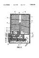
- FIG. 3is a schematic, cross-sectional elevation view of the cartridge in FIG. 2.
- FIG. 4is a cross-sectional plan view of the cartridge in FIG. 3 as viewed along line 4--4 therein.
- FIG. 5is a plan view of the shaped film shown in FIGS. 2 and 3.
- FIG. 6is a cross-sectional view of the shaped film as viewed along section line 6--6 of FIG. 5.
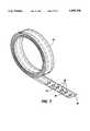
- FIG. 7is a schematic, isometric view of a roll of carrier strip containing a plurality of shaped film members releasably held thereon.
- FIG. 1is a schematic isometric view of a type of thermal ink jet printer 13 in which the printhead 14 and the ink supply therefor are combined in a single package, referred to hereinafter as cartridge 10.
- the main portion of cartridge 10is the ink supply contained in housing 12, with another portion forming the actual printhead 14.
- cartridge 10is installed in a thermal ink jet printer 13 on a carriage 15 which is translated back and forth across a recording medium 17, such as, for example, a sheet of paper, on guide rails 51.
- a recording medium 17such as, for example, a sheet of paper
- printhead 14is of such a dimension that each translation of cartridge 10 along sheet 17 enables printhead to print with a swath defined by the height of the array of nozzles in printhead and the width of the sheet. After each swath is printed, sheet 17 is indexed (by means not shown) in the direction of the arrow 19, so that any number of passes of printhead 14 may be employed to generate text or images onto the sheet 17.
- Cartridge 10also includes means, generally shown as cable 21, by which digital image data may be entered into the various heating elements (not shown) of printhead 14 to print out the desired image.
- This means 21may include, for example, plug means which are incorporated in the cartridge 10 and which accept a bus or cable from the data-processing portion (not shown) of the apparatus, and permit an operative connection therefrom to the heating elements in the printhead 14.
- FIG. 3is a schematic sectional, elevational view of cartridge 10.
- the cartridge 10has a main portion in the form of a housing 12.
- Housing 12is typically made of a lightweight but durable plastic.
- Housing 12defines an internal chamber 11 for the storage of liquid ink having a floor 25 with a ventilation port or vent 23, open to the atmosphere, and an output port or outlet 16.
- An elongated recess or trench 30is formed in the outer floor surface 26 of the thicker portion 52 of the floor 25, and may be integrally molded in the chamber surface concurrently with the fabrication of the housing 12.
- One end of the elongated recess 30is connected to the outlet 16 and the other end terminates at a location which will align with the inlet 34 of the printhead when it is attached to the chamber floor 25.
- the distance from the center of the outlet 16 to the center of the printhead inlet 34is about 10 mm.
- a relatively thin film member 36having a predetermined shape and a slot 35 therethrough, is bonded to the floor surface 26, covering the elongated recess 30.
- the slot 35is substantially the same size as the printhead inlet.
- the film memberhas opposing surfaces 31, 33, shown in FIG. 6, with the surface 31 of the film member 36 coated with a pressure sensitive adhesive 38.
- the other film member surface 33is coated with a thermosetting adhesive 50, such as, for example, a bisphenol A epoxy with V40® curing agent and adhesion promoter formulated as follows:
- this adhesivecan be cured either at room temperature in two hours or in as little as 10 minutes by raising the temperature to only 65° C. and first coating the surface of the parts to be bonded with the adhesion promoter PSO76.5®, which is a polymeric dimethoxymethylpropylsilane from Petrarch Chemicals.
- the film member 36is bonded against the bottom or outer surface 26 of the housing chamber floor 25 with any suitable pressure sensitive adhesive 38 on surface 31 of the film member or, optionally, bonded to the housing floor with same thermosetting adhesive 50 which is on the film member surface 33.
- the film memberis shaped to fit the irregular floor surface 26 and to avoid the locating and fastening pins 40 integrally formed or molded with the housing and used to fixedly attach the printhead 14 and heat sink 24, as discussed later.
- the elongated recess 30is hermetically sealed by the film member to form a closed ink passageway from the cartridge chamber 11 to the printhead nozzles 37.
- the film memberis fabricated by coating the desired adhesive on both sides of a long strip of polyester film, such as Mylar®, having a thickness of about 7 mils.
- the adhesive on the surface 31 of the film stripis then laminated to a 4 mils thick polyester release carrier strip 50 (FIG. 7) on the side which will bond to the chamber floor and with a thinner polyester release cover (not shown) on the other side, which has a thickness of about 1.5 mils.
- a progressive punching operationis used to first punch through the critical features of ink slot 35 and front edge 39 which is coplanar with the printhead nozzle face 42 and then the remaining profile or periphery of the film member is just scored to a depth of only 1 mil into the 4 mil polyester release carrier.
- the scrap materialis then removed leaving a complete film member with thinner release cover thereover spaced every 1.5 inches down a 4,000 inch long polyester carrier strip.
- the reel of scored film membersare fed into a pick and place zone of a robotic device (not shown) and the film members are vacuum picked off the carrier strip, positioned to the housing floor surface 26 using a vision system (not shown), and placed onto the housing floor surface with a specified pressure by the robotic device.
- the top thinner release coveris then removed with a higher tack tape or mechanical picker (neither shown) and the printhead and heat sink assembly is aligned and placed onto the awaiting film member.
- the printhead 14is bonded to the heat sink 24, so that the printhead inlet 34 is facing in a direction perpendicular to the heat sink.
- a printed circuit board 44is also bonded to the heat sink adjacent the printhead.
- the terminals or contact pads (not shown) of the printhead 14 and circuit board 44are interconnected by wire bonds 45.
- Locating holes 43 in the heat sinkare used when mounting the heat sink 24 with printhead 14 and circuit board 44 bonded thereto to align the printhead inlet and nozzle face relative to the housing by inserting the housing stake pins 40 therein. Stake pins 40 are then ultrasonically staked to form pin heads 41 and the attachment of the printhead and heat sink assembly is complete.
- the stake pinsmay be bonded to locating holes 43 in addition to being staked.
- the wire bonds 45are encapsulated with a thermally curable passivation material (not shown) by, for example, an injection syringe, which fills the cavity behind the printhead and covers the wire bonds.
- a thermally curable passivation material(not shown) by, for example, an injection syringe, which fills the cavity behind the printhead and covers the wire bonds.
- the housing and attached heat sink with printhead and circuit boardis cured in an oven, thus simultaneously curing the thermosetting adhesive 50 and the wire bond encapsulating passivation material.
- Cosmetic bottom cover 28 with ventilation openings 29is positioned on the housing over the printhead and heat sink assembly and ultrasonically welded to the housing.
- the nozzle face 42 of the printhead 14is coplanar with the heat sink 24 and a portion of the upper edge of the housing chamber floor 25.
- This region of the cartridge 10is covered by a rectangular shaped frame 48 having a lip 57 around the outer edge thereof and extending in a direction towards the housing.
- the void area between the frame and the housingis filled with another passivation material (not shown) to form a hermetic seal completely around the printhead.
- the ink holding medium 18is shown as three separate portions, occupying most of the chamber 11.
- the ink holding mediumis saturated with ink and the top housing cover 27 of the same durable plastic material as the housing is placed on the housing and ultrasonically welded thereto.
- FIG. 2an exploded isometric view of the cartridge 10, the various elements of the cartridge may be viewed which forms a compact customer replaceable unit.
- a tube 47extends from the vent 23 to center of the interior of chamber 11 in the housing and through openings in each of the ink holding mediums.
- the printheadswill have on-board circuitry for selectively activating the heating elements (not shown) of the thermal ink jet printhead 14 as addressed by electrical signals for the printer controller (not shown) which connects to the cartridge printed circuit board 44 by the cable 21 (FIG. 1) when the cartridge is installed on the carriage 15.
- medium 18(shown as three portions of material) is in the form of a needled felt of polyester fibers. Needled felt is made of fibers physically interlocked by the action of, for example, a needle loom, although in addition the fibers may be matted together by soaking or steam heating. According to the preferred embodiment of the present invention, the needled felt should be of a density of between 0.06 and 0.13 grams per cubic centimeter. It has been found that the optimum density of this polyester needled felt forming medium 18 is 0.095 grams per cubic centimeter. This optimum density reflects the most advantageous volume efficiency, as described above, for holding liquid ink. A type of felt suitable for this purpose is manufactured by BMP of America, Medina, N.Y.
- an advantageous composition of needled feltcomprises approximately equal proportions of 6 denier and 16 denier polyester fibers.
- Medium 18is packed inside the chamber 11 of housing 12 in such a manner that the felt exerts reasonable contact and compression against the inner walls.
- the medium 18is created by stacking three layers of needled felt, each one-half inch in thickness, and packing them inside the housing 12.
- scavenger 20is a member made of a material providing a high capillary pressure, indicated as scavenger 20.
- Scavenger 20is a relatively small member which serves as a porous capillary barrier between the medium 18 and the output port 16, which leads to the passageway formed by the elongated recess 30 in the chamber floor 25 and the film member 36.
- scavenger 20is made of an acoustic melamine foam, which is felted (compressed with heat and pressure) by 50% in the direction of intended ink flow.
- the scavenger 20preferably further includes a filter cloth, indicated as 22, which is attached to the reelamine using a porous hot-melt laminating adhesive.
- the preferred material for the filter cloth 22is monofilament polyester screening fabric. This filtered cloth provides a number of practical advantages. Typically, no specific structure (such as a wire mesh) for holding the scavenger 20 against the opening into outlet port 16 is necessary. Further, there need not be any adhesive between the filter cloth 22 and the outlet port 16.
- the high capillary force provided by filter cloth 22creates a film of ink between the filter cloth 22 and the outlet port 16, by virtue of the planarity (no wrinkles or bumps) of the filter cloth 22 against the scavenger 20, the compression of the scavenger 20 against the outlet port 16, and the saturation of the scavenger 20.
- This filmserves to block out air from the outlet port 16.
- FIG. 3it can be seen that one portion of the outer surface of scavenger 20 abuts the ink holding medium 18, while other portions of the surface are exposed to open space 49 between the medium 18 and the inner walls of chamber 11.
- the single chamber 11is so designed that a given quantity of ink may conceivably flow from the medium 18 to and through the scavenger 20, which has a higher capillarity than the medium 18, and through the filter 22, which has a higher capillarity than the scavenger, to the outlet 16 and through the passageway formed by the elongated recess and film member to the printhead inlet 34.
- FIG. 4is a bottom view of the housing 12 as viewed along view-line 4--4, and shows the geometric shape of the film member 36 required to fit the shape of the housing floor surface 26 in this region of the housing floor 25 and to avoid stake pins 40.
- the film memberis bonded to the surface 26 of housing floor 25 and covers the elongated recess 30 and outlet 16 connected thereto, shown in dashed line.
- the passageway formed by the elongated recess 30 and film member 36terminates at the through slot 35, which is similar in size and shape as the printhead inlet 34.
- thermosetting adhesive 50preferably the above mentioned bisphenol A epoxy formulation
- FIG. 5shows the film member 36 with through slot 35
- FIG. 6is a cross-sectional view of the film member in FIG. 5 as viewed along section line 6--6, and shows the film member slot 35, holes 58 which are used by the robotic device for alignment, surface 31 with the pressure sensitive adhesive 38 thereon, and film member surface 33 with the thermosetting adhesive 50 thereon, preferably the bisphenol A epoxy formulation delineated above.
- the thermosetting adhesive 50may be used on both surfaces of the film member 36.
- the selection of the adhesive used on the surfaces of the film member 36is critical. As is evident in FIG. 3, the ink must flow against the exposed adhesive 38 on surface 31 of the film member 36. This adhesive must be resistant to chemical and erosion attack by the ink; otherwise, the ink would be contaminated by the adhesive and the ink may leak between the housing floor 25 and the film member.
- the adhesive 38must be liquid enough to wet the housing floor surface 26 and the film member surface 31, but cannot be too liquid, so as to flow into the slot 35 in the film member or onto the nozzle face 42 of the printhead 14, either during or after assembly of the cartridge 10.
- the adhesive on film member surface 31must also be sufficiently adhesive in nature that it does not move during or after assembly and will assist in the mechanical integrity of the cartridge.
- the adhesive 38must also be tolerant of the temperatures in excess of 150° C. that are experienced as part of the encapsulation cure process.
- One pressure sensitive adhesive that is satisfactorilyis AS-105,® a high temperature, pressure-sensitive, acrylic adhesive sold by the Adhesive Research Co.
- the thermosetting adhesive 50must have substantially the same characteristics of resistance to chemical and erosion attack by the ink and controlled flowability to prevent flow into film member slot 35 and printhead inlet 34 and onto the nozzle face 42.
- the working life of the bisphenol A epoxy formulationis about 48 hours if maintained at a temperature of 10° C. This temperature may be maintained by, for example, providing a cooling jacket around a dispensing syringe (not shown).
- the overall pot life of the epoxy formulation 50is in excess of 30 days, if the epoxy formulation is frozen.
- the bonding strength in the presence of high PH thermal ink jet inksis very high and is believed to be due to a reaction between the adhesive promoter and water in the inks.
- the bisphenol A epoxy formulationprovides the needed qualities of dispensability with time by a syringe, curing at temperature suitable for other materials used in the fabrication process for the cartridge, high strength bonding to assume a fluidic seal around the printhead inlet, and ink compatibility.
Landscapes
- Particle Formation And Scattering Control In Inkjet Printers (AREA)
Abstract
Description
______________________________________ Solvent: 30:70 mixture (by wt) of methyl-iso-butyl ketone and xylene Resin: 1001F Curing Agent: V40 ® Ratio of curing agent to resin: 1:3 Ratio to solvent mixture to resin 1:3 + curing agent mixture ______________________________________
Claims (8)
Priority Applications (1)
| Application Number | Priority Date | Filing Date | Title |
|---|---|---|---|
| US08/425,270US5696546A (en) | 1993-11-15 | 1995-04-17 | Ink supply cartridge with ink jet printhead having improved fluid seal therebetween |
Applications Claiming Priority (2)
| Application Number | Priority Date | Filing Date | Title |
|---|---|---|---|
| US15162293A | 1993-11-15 | 1993-11-15 | |
| US08/425,270US5696546A (en) | 1993-11-15 | 1995-04-17 | Ink supply cartridge with ink jet printhead having improved fluid seal therebetween |
Related Parent Applications (1)
| Application Number | Title | Priority Date | Filing Date |
|---|---|---|---|
| US15162293AContinuation | 1993-11-15 | 1993-11-15 |
Publications (1)
| Publication Number | Publication Date |
|---|---|
| US5696546Atrue US5696546A (en) | 1997-12-09 |
Family
ID=22539550
Family Applications (1)
| Application Number | Title | Priority Date | Filing Date |
|---|---|---|---|
| US08/425,270Expired - LifetimeUS5696546A (en) | 1993-11-15 | 1995-04-17 | Ink supply cartridge with ink jet printhead having improved fluid seal therebetween |
Country Status (1)
| Country | Link |
|---|---|
| US (1) | US5696546A (en) |
Cited By (20)
| Publication number | Priority date | Publication date | Assignee | Title |
|---|---|---|---|---|
| US6210522B1 (en) | 1999-06-15 | 2001-04-03 | Lexmark International, Inc. | Adhesive bonding laminates |
| US6229114B1 (en) | 1999-09-30 | 2001-05-08 | Xerox Corporation | Precision laser cutting of adhesive members |
| US6270211B1 (en) | 1999-07-07 | 2001-08-07 | Lexmark International, Inc. | Bubble elimination and filter tower structure |
| US6372018B1 (en)* | 2000-03-14 | 2002-04-16 | Harold R. Cowles | VOC removal or destruction system |
| US6388231B1 (en) | 2000-06-15 | 2002-05-14 | Xerox Corporation | Systems and methods for controlling depths of a laser cut |
| US6398354B1 (en) | 1999-06-30 | 2002-06-04 | Lexmark International, Inc. | Printhead apparatus and printer having separate filtration device and method for attaching said device |
| US6406129B1 (en)* | 2000-10-20 | 2002-06-18 | Silverbrook Research Pty Ltd | Fluidic seal for moving nozzle ink jet |
| US6428147B2 (en) | 1997-07-15 | 2002-08-06 | Silverbrook Research Pty Ltd | Ink jet nozzle assembly including a fluidic seal |
| US20030131930A1 (en)* | 2000-07-17 | 2003-07-17 | Singh Jeanne Marie Saldanha | Method and apparatus for adhesively securing ink jet pen components using thin film adhesives |
| US6663235B2 (en) | 2001-10-31 | 2003-12-16 | Hewlett-Packard Development Company, L.P. | Coverlayer based on functional polymers |
| US20040135855A1 (en)* | 2003-01-15 | 2004-07-15 | Xerox Corporation | Ink tank with capillary member |
| US20050156985A1 (en)* | 2004-01-21 | 2005-07-21 | Silverbrook Research Pty Ltd. | Inkjet printhead with integrated circuit mounted on polymer sealing film |
| US20050168542A1 (en)* | 2004-01-21 | 2005-08-04 | Akira Nakazawa | Printhead chip having longitudinal ink supply channels interrupted by transverse bridges |
| US20050168541A1 (en)* | 2004-01-21 | 2005-08-04 | Akira Nakazawa | Printhead chip having low aspect ratio ink supply channels |
| US20050168543A1 (en)* | 2004-01-21 | 2005-08-04 | Silverbrook Research Pty Ltd | Printhead chip having longitudinal ink supply channels |
| US20060125892A1 (en)* | 2004-12-10 | 2006-06-15 | Lexmark International, Inc. | Inkjet printhead with bubble handling properties |
| US20070126809A1 (en)* | 2005-12-02 | 2007-06-07 | Xerox Corporation | Ink delivery system |
| US20090231384A1 (en)* | 2008-03-17 | 2009-09-17 | Silverbrook Research Pty Ltd | Printhead integrated circuit attachment film having differentiated adhesive layers |
| US20110085010A1 (en)* | 2008-03-17 | 2011-04-14 | Silverbrook Research Pty Ltd | Printhead assembly with minimal leakage |
| US10046570B2 (en) | 2016-01-13 | 2018-08-14 | Océ Holding B.V. | Filter device for filtering ink and ink supply system for printing apparatus |
Citations (12)
| Publication number | Priority date | Publication date | Assignee | Title |
|---|---|---|---|---|
| US3903048A (en)* | 1973-04-02 | 1975-09-02 | United States Steel Corp | Catalyst systems for lowering epoxy resin cure temperatures |
| US4095237A (en)* | 1974-12-26 | 1978-06-13 | Aktiebolaget Electrolux | Ink jet printing head |
| US4419678A (en)* | 1979-10-17 | 1983-12-06 | Canon Kabushiki Kaisha | Ink jet recording apparatus |
| US4463359A (en)* | 1979-04-02 | 1984-07-31 | Canon Kabushiki Kaisha | Droplet generating method and apparatus thereof |
| US4771295A (en)* | 1986-07-01 | 1988-09-13 | Hewlett-Packard Company | Thermal ink jet pen body construction having improved ink storage and feed capability |
| US4774530A (en)* | 1987-11-02 | 1988-09-27 | Xerox Corporation | Ink jet printhead |
| US4791438A (en)* | 1987-10-28 | 1988-12-13 | Hewlett-Packard Company | Balanced capillary ink jet pen for ink jet printing systems |
| US5086307A (en)* | 1990-03-21 | 1992-02-04 | Canon Kabushiki Kaisha | Liquid jet recording head |
| US5221397A (en)* | 1992-11-02 | 1993-06-22 | Xerox Corporation | Fabrication of reading or writing bar arrays assembled from subunits |
| US5233369A (en)* | 1990-12-27 | 1993-08-03 | Xerox Corporation | Method and apparatus for supplying ink to an ink jet printer |
| US5252694A (en)* | 1992-01-22 | 1993-10-12 | Minnesota Mining And Manufacturing Company | Energy-polymerization adhesive, coating, film and process for making the same |
| US5289212A (en)* | 1992-05-19 | 1994-02-22 | Xerox Corporation | Air vent for an ink supply cartridge in a thermal ink-jet printer |
- 1995
- 1995-04-17USUS08/425,270patent/US5696546A/ennot_activeExpired - Lifetime
Patent Citations (13)
| Publication number | Priority date | Publication date | Assignee | Title |
|---|---|---|---|---|
| US3903048A (en)* | 1973-04-02 | 1975-09-02 | United States Steel Corp | Catalyst systems for lowering epoxy resin cure temperatures |
| US4095237A (en)* | 1974-12-26 | 1978-06-13 | Aktiebolaget Electrolux | Ink jet printing head |
| US4463359A (en)* | 1979-04-02 | 1984-07-31 | Canon Kabushiki Kaisha | Droplet generating method and apparatus thereof |
| US4419678A (en)* | 1979-10-17 | 1983-12-06 | Canon Kabushiki Kaisha | Ink jet recording apparatus |
| US4771295A (en)* | 1986-07-01 | 1988-09-13 | Hewlett-Packard Company | Thermal ink jet pen body construction having improved ink storage and feed capability |
| US4771295B1 (en)* | 1986-07-01 | 1995-08-01 | Hewlett Packard Co | Thermal ink jet pen body construction having improved ink storage and feed capability |
| US4791438A (en)* | 1987-10-28 | 1988-12-13 | Hewlett-Packard Company | Balanced capillary ink jet pen for ink jet printing systems |
| US4774530A (en)* | 1987-11-02 | 1988-09-27 | Xerox Corporation | Ink jet printhead |
| US5086307A (en)* | 1990-03-21 | 1992-02-04 | Canon Kabushiki Kaisha | Liquid jet recording head |
| US5233369A (en)* | 1990-12-27 | 1993-08-03 | Xerox Corporation | Method and apparatus for supplying ink to an ink jet printer |
| US5252694A (en)* | 1992-01-22 | 1993-10-12 | Minnesota Mining And Manufacturing Company | Energy-polymerization adhesive, coating, film and process for making the same |
| US5289212A (en)* | 1992-05-19 | 1994-02-22 | Xerox Corporation | Air vent for an ink supply cartridge in a thermal ink-jet printer |
| US5221397A (en)* | 1992-11-02 | 1993-06-22 | Xerox Corporation | Fabrication of reading or writing bar arrays assembled from subunits |
Non-Patent Citations (1)
| Title |
|---|
| Xerox Disclosure Journal, vol. 16, No. 4, Jul./Aug. 1991, p. 233.* |
Cited By (46)
| Publication number | Priority date | Publication date | Assignee | Title |
|---|---|---|---|---|
| US6428147B2 (en) | 1997-07-15 | 2002-08-06 | Silverbrook Research Pty Ltd | Ink jet nozzle assembly including a fluidic seal |
| US6210522B1 (en) | 1999-06-15 | 2001-04-03 | Lexmark International, Inc. | Adhesive bonding laminates |
| US6398354B1 (en) | 1999-06-30 | 2002-06-04 | Lexmark International, Inc. | Printhead apparatus and printer having separate filtration device and method for attaching said device |
| US6270211B1 (en) | 1999-07-07 | 2001-08-07 | Lexmark International, Inc. | Bubble elimination and filter tower structure |
| US6229114B1 (en) | 1999-09-30 | 2001-05-08 | Xerox Corporation | Precision laser cutting of adhesive members |
| US6372018B1 (en)* | 2000-03-14 | 2002-04-16 | Harold R. Cowles | VOC removal or destruction system |
| US6388231B1 (en) | 2000-06-15 | 2002-05-14 | Xerox Corporation | Systems and methods for controlling depths of a laser cut |
| US6758934B2 (en) | 2000-07-17 | 2004-07-06 | Lexmark International, Inc. | Method and apparatus for adhesively securing ink jet pen components using thin film adhesives |
| US20030131930A1 (en)* | 2000-07-17 | 2003-07-17 | Singh Jeanne Marie Saldanha | Method and apparatus for adhesively securing ink jet pen components using thin film adhesives |
| US6406129B1 (en)* | 2000-10-20 | 2002-06-18 | Silverbrook Research Pty Ltd | Fluidic seal for moving nozzle ink jet |
| US6663235B2 (en) | 2001-10-31 | 2003-12-16 | Hewlett-Packard Development Company, L.P. | Coverlayer based on functional polymers |
| US20040135855A1 (en)* | 2003-01-15 | 2004-07-15 | Xerox Corporation | Ink tank with capillary member |
| US6951387B2 (en) | 2003-01-15 | 2005-10-04 | Xerox Corporation | Ink tank with capillary member |
| US7441865B2 (en)* | 2004-01-21 | 2008-10-28 | Silverbrook Research Pty Ltd | Printhead chip having longitudinal ink supply channels |
| US7686440B2 (en) | 2004-01-21 | 2010-03-30 | Silverbrook Research Pty Ltd | Ink storage module with a valve insert to facilitate refilling thereof |
| US20050168543A1 (en)* | 2004-01-21 | 2005-08-04 | Silverbrook Research Pty Ltd | Printhead chip having longitudinal ink supply channels |
| US20050168542A1 (en)* | 2004-01-21 | 2005-08-04 | Akira Nakazawa | Printhead chip having longitudinal ink supply channels interrupted by transverse bridges |
| US9346276B2 (en) | 2004-01-21 | 2016-05-24 | Memjet Technology Limited | Removable printhead cartridge having plurality of printhead chips |
| US9102152B2 (en) | 2004-01-21 | 2015-08-11 | Memjet Technology Ltd. | Removable printhead assembly for single-pass inkjet printer |
| US9056478B2 (en) | 2004-01-21 | 2015-06-16 | Memjet Technology Ltd. | Ink distribution member for mounting printhead integrated circuit |
| US7367650B2 (en)* | 2004-01-21 | 2008-05-06 | Silverbrook Research Pty Ltd | Printhead chip having low aspect ratio ink supply channels |
| US20080186368A1 (en)* | 2004-01-21 | 2008-08-07 | Silverbrook Research Pty Ltd | Ink Storage Module With A Valve Insert To Facilitate Refilling Thereof |
| US20050156985A1 (en)* | 2004-01-21 | 2005-07-21 | Silverbrook Research Pty Ltd. | Inkjet printhead with integrated circuit mounted on polymer sealing film |
| US7469989B2 (en)* | 2004-01-21 | 2008-12-30 | Silverbrook Research Pty Ltd | Printhead chip having longitudinal ink supply channels interrupted by transverse bridges |
| US20090002466A1 (en)* | 2004-01-21 | 2009-01-01 | Silverbrook Research Pty Ltd | Ink Storage Module |
| US8678549B2 (en) | 2004-01-21 | 2014-03-25 | Zamtec Ltd | Printhead integrated circuit having frontside inlet channels and backside ink supply channels |
| US20090058957A1 (en)* | 2004-01-21 | 2009-03-05 | Silverbrook Research Pty Ltd | Printhead integrated circuit having longitudinal ink supply channels reinforced by transverse walls |
| US7585054B2 (en)* | 2004-01-21 | 2009-09-08 | Silverbrook Research Pty Ltd | Inkjet printhead with integrated circuit mounted on polymer sealing film |
| US8434858B2 (en) | 2004-01-21 | 2013-05-07 | Zamtec Ltd | Cartridge unit for printer |
| US20090295864A1 (en)* | 2004-01-21 | 2009-12-03 | Silverbrook Research Pty Ltd | Printhead Assembly With Ink Supply To Nozzles Through Polymer Sealing Film |
| US20050168541A1 (en)* | 2004-01-21 | 2005-08-04 | Akira Nakazawa | Printhead chip having low aspect ratio ink supply channels |
| US7735986B2 (en) | 2004-01-21 | 2010-06-15 | Silverbrook Research Pty Ltd | Ink storage module |
| US20100171800A1 (en)* | 2004-01-21 | 2010-07-08 | Silverbrook Research Pty Ltd | Ink storage module with displaceable upper and lower plates and displaceable upper and lower collars |
| US8382266B2 (en) | 2004-01-21 | 2013-02-26 | Zamtec Ltd | Ink storage module with displaceable upper and lower plates and displaceable upper and lower collars |
| US8079664B2 (en) | 2004-01-21 | 2011-12-20 | Silverbrook Research Pty Ltd | Printer with printhead chip having ink channels reinforced by transverse walls |
| US7971960B2 (en) | 2004-01-21 | 2011-07-05 | Silverbrook Research Pty Ltd | Printhead integrated circuit having longitudinal ink supply channels reinforced by transverse walls |
| US8070266B2 (en) | 2004-01-21 | 2011-12-06 | Silverbrook Research Pty Ltd | Printhead assembly with ink supply to nozzles through polymer sealing film |
| US7201476B2 (en) | 2004-12-10 | 2007-04-10 | Lexmark International, Inc. | Inkjet printhead with bubble handling properties |
| US20060125892A1 (en)* | 2004-12-10 | 2006-06-15 | Lexmark International, Inc. | Inkjet printhead with bubble handling properties |
| US7475971B2 (en) | 2005-12-02 | 2009-01-13 | Xerox Corporation | Ink delivery system |
| US20070126809A1 (en)* | 2005-12-02 | 2007-06-07 | Xerox Corporation | Ink delivery system |
| US20110085010A1 (en)* | 2008-03-17 | 2011-04-14 | Silverbrook Research Pty Ltd | Printhead assembly with minimal leakage |
| US7845755B2 (en)* | 2008-03-17 | 2010-12-07 | Silverbrook Research Pty Ltd | Printhead integrated circuit attachment film having differentiated adhesive layers |
| US20090231384A1 (en)* | 2008-03-17 | 2009-09-17 | Silverbrook Research Pty Ltd | Printhead integrated circuit attachment film having differentiated adhesive layers |
| US8444252B2 (en) | 2008-03-17 | 2013-05-21 | Zamtec Ltd | Printhead assembly with minimal leakage |
| US10046570B2 (en) | 2016-01-13 | 2018-08-14 | Océ Holding B.V. | Filter device for filtering ink and ink supply system for printing apparatus |
Similar Documents
| Publication | Publication Date | Title |
|---|---|---|
| US5696546A (en) | Ink supply cartridge with ink jet printhead having improved fluid seal therebetween | |
| US5519425A (en) | Ink supply cartridge for an ink jet printer | |
| US5563643A (en) | Ink jet printhead and ink supply manifold assembly having ink passageway sealed therebetween | |
| JP3833123B2 (en) | Inkjet head stored and method for storing inkjet head | |
| US5289212A (en) | Air vent for an ink supply cartridge in a thermal ink-jet printer | |
| EP0571151B1 (en) | Ink supply system for a thermal ink-jet printer | |
| JP3252392B2 (en) | Ink-jet recording apparatus and recording head cleaning method | |
| EP0538842B1 (en) | Process for producing an ink jet recording head | |
| KR100254763B1 (en) | Ink refill techniques for an inkjet print cartridge which leave correct back pressure | |
| JPH071743A (en) | Negative pressure ink supply system | |
| JPH02522A (en) | Ink jet-pen | |
| JPH04278360A (en) | Ink cartridge for ink jet printer | |
| US5969739A (en) | Ink-jet pen with rectangular ink pipe | |
| JP2005161635A (en) | Ink tank and ink supply device | |
| JPH11170559A (en) | Ink jet coartridge | |
| JP2670464B2 (en) | Recording head cartridge, ink tank, and inkjet device | |
| US5898449A (en) | Interface seal between printhead and ink supply cartridge | |
| EP0709211B1 (en) | Ink-tank pen with near, net size porous member | |
| CA2631365A1 (en) | Filter/wicking structure for micro-fluid ejection head | |
| US6533405B1 (en) | Preserving inkjet print cartridge reliability while packaged | |
| EP0709209B1 (en) | Ink-container with porous member cover slip | |
| JPH0789088A (en) | Ink supplying device | |
| GB2301064A (en) | Ink-jet pen with rectangular ink pipe | |
| JP2931511B2 (en) | Head cartridge and printing device | |
| JP2840408B2 (en) | INK JET PRINT HEAD AND INK JET PRINTING APPARATUS HAVING THE SAME |
Legal Events
| Date | Code | Title | Description |
|---|---|---|---|
| STCF | Information on status: patent grant | Free format text:PATENTED CASE | |
| FPAY | Fee payment | Year of fee payment:4 | |
| AS | Assignment | Owner name:BANK ONE, NA, AS ADMINISTRATIVE AGENT, ILLINOIS Free format text:SECURITY INTEREST;ASSIGNOR:XEROX CORPORATION;REEL/FRAME:013153/0001 Effective date:20020621 | |
| AS | Assignment | Owner name:JPMORGAN CHASE BANK, AS COLLATERAL AGENT, TEXAS Free format text:SECURITY AGREEMENT;ASSIGNOR:XEROX CORPORATION;REEL/FRAME:015134/0476 Effective date:20030625 Owner name:JPMORGAN CHASE BANK, AS COLLATERAL AGENT,TEXAS Free format text:SECURITY AGREEMENT;ASSIGNOR:XEROX CORPORATION;REEL/FRAME:015134/0476 Effective date:20030625 | |
| FPAY | Fee payment | Year of fee payment:8 | |
| FPAY | Fee payment | Year of fee payment:12 | |
| AS | Assignment | Owner name:XEROX CORPORATION, CONNECTICUT Free format text:RELEASE BY SECURED PARTY;ASSIGNOR:JPMORGAN CHASE BANK, N.A. AS SUCCESSOR-IN-INTEREST ADMINISTRATIVE AGENT AND COLLATERAL AGENT TO JPMORGAN CHASE BANK;REEL/FRAME:066728/0193 Effective date:20220822 |