US5696352A - Stranded electrical wire for use with IDC - Google Patents
Stranded electrical wire for use with IDCDownload PDFInfo
- Publication number
- US5696352A US5696352AUS08/503,465US50346595AUS5696352AUS 5696352 AUS5696352 AUS 5696352AUS 50346595 AUS50346595 AUS 50346595AUS 5696352 AUS5696352 AUS 5696352A
- Authority
- US
- United States
- Prior art keywords
- strands
- wire
- idc
- serrations
- strand
- Prior art date
- Legal status (The legal status is an assumption and is not a legal conclusion. Google has not performed a legal analysis and makes no representation as to the accuracy of the status listed.)
- Expired - Fee Related
Links
- 238000009413insulationMethods0.000claimsdescription6
- 230000008602contractionEffects0.000abstractdescription5
- RYGMFSIKBFXOCR-UHFFFAOYSA-NCopperChemical compound[Cu]RYGMFSIKBFXOCR-UHFFFAOYSA-N0.000description2
- 239000004020conductorSubstances0.000description2
- 238000002788crimpingMethods0.000description2
- 229910052802copperInorganic materials0.000description1
- 239000010949copperSubstances0.000description1
- 230000007423decreaseEffects0.000description1
- 238000000034methodMethods0.000description1
- 230000002093peripheral effectEffects0.000description1
Images
Classifications
- H—ELECTRICITY
- H01—ELECTRIC ELEMENTS
- H01B—CABLES; CONDUCTORS; INSULATORS; SELECTION OF MATERIALS FOR THEIR CONDUCTIVE, INSULATING OR DIELECTRIC PROPERTIES
- H01B7/00—Insulated conductors or cables characterised by their form
- H01B7/0009—Details relating to the conductive cores
- H—ELECTRICITY
- H01—ELECTRIC ELEMENTS
- H01R—ELECTRICALLY-CONDUCTIVE CONNECTIONS; STRUCTURAL ASSOCIATIONS OF A PLURALITY OF MUTUALLY-INSULATED ELECTRICAL CONNECTING ELEMENTS; COUPLING DEVICES; CURRENT COLLECTORS
- H01R4/00—Electrically-conductive connections between two or more conductive members in direct contact, i.e. touching one another; Means for effecting or maintaining such contact; Electrically-conductive connections having two or more spaced connecting locations for conductors and using contact members penetrating insulation
- H01R4/58—Electrically-conductive connections between two or more conductive members in direct contact, i.e. touching one another; Means for effecting or maintaining such contact; Electrically-conductive connections having two or more spaced connecting locations for conductors and using contact members penetrating insulation characterised by the form or material of the contacting members
- D—TEXTILES; PAPER
- D07—ROPES; CABLES OTHER THAN ELECTRIC
- D07B—ROPES OR CABLES IN GENERAL
- D07B2201/00—Ropes or cables
- D07B2201/20—Rope or cable components
- D07B2201/2015—Strands
- D07B2201/2016—Strands characterised by their cross-sectional shape
- D—TEXTILES; PAPER
- D07—ROPES; CABLES OTHER THAN ELECTRIC
- D07B—ROPES OR CABLES IN GENERAL
- D07B5/00—Making ropes or cables from special materials or of particular form
- D07B5/005—Making ropes or cables from special materials or of particular form characterised by their outer shape or surface properties
- H—ELECTRICITY
- H01—ELECTRIC ELEMENTS
- H01R—ELECTRICALLY-CONDUCTIVE CONNECTIONS; STRUCTURAL ASSOCIATIONS OF A PLURALITY OF MUTUALLY-INSULATED ELECTRICAL CONNECTING ELEMENTS; COUPLING DEVICES; CURRENT COLLECTORS
- H01R4/00—Electrically-conductive connections between two or more conductive members in direct contact, i.e. touching one another; Means for effecting or maintaining such contact; Electrically-conductive connections having two or more spaced connecting locations for conductors and using contact members penetrating insulation
- H01R4/24—Connections using contact members penetrating or cutting insulation or cable strands
Definitions
- This inventionrelates to stranded electrical wire for use with insulation displacing contacts (IDC) whereby the strands of the wire have peripheral serrations to reduce relative slipping movement between the strands thereby reducing the relaxation of the contact pressure between the wire and contact blades of an IDC when connected thereto.
- IDCinsulation displacing contacts
- Multi-stranded electrical wireis widespreadly used in the electrical industry, the wire commonly consisting of a plurality of cylindrical copper wire strands bundled and held together with an outer insulative jacket usually of some sort of plastic.
- the strandsare not necessarily cylindrical depending on the requirements to have a more or less compact arrangement of the strands, an example of which is shown in U.S. Pat. No. 5,133,121.
- IDC technologyThere are a number of commonly used techniques to connect electrical wire to a conductor, some of the most common being by crimping or by IDC technology. The use of IDC technology is ever-increasing as it is well adapted for cost-effective automated connection of conducting wires to electrical connectors.
- IDC connectionsare typically made by forcing an insulated conducting wire between a pair of spaced apart and opposed metallic blades that cut through the insulation and enter into contact with some of the strands of the electrical wire.
- the IDC bladesonly apply pressure to the wire on opposing sides thereof, the pressure will tend to deform the wire into an oval shape by pushing the strands of the wire towards the area of low pressure i.e. the slot openings.
- Deformation of the wireis however limited by the insulation jacket which nevertheless holds the strands bundled together. Further slipping of the strands between each other, during the lifetime of the connection, decreases the contact pressure between the strands and the IDC, and also between the strands themselves, this movement being generated by various factors such as vibration and thermal expansion and contraction.
- a stranded electrical wirecomprising a plurality of longitudinal filiform conducting strands substantially held together, each strand comprising an outer surface in contact with adjacent strands, characterized in that the outer surface comprises radial serrations extending longitudinally along the strand to reduce slipping movement between adjacent strands in a direction substantially perpendicular to the longitudinal direction of the strands.
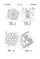
- FIG. 1is a cross-sectional view of a prior art multi-stranded electrical wire
- FIG. 2is a cross-sectional view through the wire of FIG. 1 inserted into an IDC slot;
- FIG. 3is a cross-sectional view through a multi-stranded electrical wire according to the preferred embodiment of this invention.
- FIG. 4is a partial isometric view of the wire shown in FIG. 3.
- a conventional multi-stranded conducting wire 2'comprises a plurality of filiform cylindrical conducting strands 4' bundled together and surrounded by an insulative outer jacket 6'.
- the strands 4'are typically made of a good conducting material such as copper.
- Each strand 4'has a smooth outer surface 8' which is in contact, at contact points 10', to adjacent strands.
- an insulation displacing contact (IDC) 20comprising a pair of opposed blades 22 having blade contact edges 24 forming a wire receiving slot 23.
- the conducting wire 2'is shown stuffed between the blades 22, the blade edges 24 having cut through part of the insulating jacket 6' and making electrical contact with a few outer strands 26' of the wire 2'.
- the pressure of the blade edges 24 against the strands 26'causes the other strands 4' not in contact with the blade edges 24, to be pushed towards open ends 28 of the wire receiving slot 23 such that the cross-section of the wire 2', in the plane of the IDC blades 22, takes on a substantially oval shape 30'.
- the original circular profile of the wire 2'is shown by the phantom line 32'.
- the strands 4'are nevertheless held together by the outer insulation jacket 6'.
- the movement of the strands 4' towards the slot openings 28reduces the contact pressure between adjacent strands, and also the contact pressure between the strands 26' and blade contact edges 24. Further slipping movement between strands due to vibration, or thermal expansion and contraction cycles, will tend to move the strands such that pressure therebetween is reduced, thereby reducing the electrical conductivity therebetween. The electrical current carrying capability of the connection between the IDC 20 and wire 2' is thus reduced by mechanical and thermal solicitation, and therefore unreliable.
- the preferred embodiment of this inventionis a multi-stranded electrical wire 2 comprising a plurality of conducting strands 4 bundled and held together by an outer insulative jacket 6.
- Each strand 4has an outer surface 8 comprising serrations 12 having pointed tips 14 directed radially outwards, the serrations 12 disposed around the circumference of the strands 4 and extending longitudinally therealong.
- the pointed tips 14 of adjacent strands 4interlock, and also provide electrical contact between strands at interlocking zones 10.
- Interlocking of the serrations 12inhibits slipping movement between adjacent strands 4 such that when the wire 2 is forced into an IDC slot 23, slipping of the strands relative to each other will be reduced thereby maintaining a higher contact pressure and thus a higher conductivity between the strands 4.
- the reliability and quality of the connectionwill also be increased during the lifetime thereof, especially when subjected to mechanical solicitation such as vibration or thermal movements due to expansion and contraction, by preventing slipping movement between the strands, which as already mentioned, could reduce the contact pressure and therefore the electrical conductivity between the wire and IDC.
- the serrated strandsinhibit slipping therebetween, which is particularly important when the conducting wire is subject to vibration or thermal expansion and contraction, the contact pressure thereby maintained and increasing not only the electrical conductivity of the connection but also it's reliability.
Landscapes
- Connections Effected By Soldering, Adhesion, Or Permanent Deformation (AREA)
- Non-Insulated Conductors (AREA)
- Insulated Conductors (AREA)
Abstract
Description
1. Field of the Invention
This invention relates to stranded electrical wire for use with insulation displacing contacts (IDC) whereby the strands of the wire have peripheral serrations to reduce relative slipping movement between the strands thereby reducing the relaxation of the contact pressure between the wire and contact blades of an IDC when connected thereto.
2. Description of the Prior Art
Multi-stranded electrical wire is widespreadly used in the electrical industry, the wire commonly consisting of a plurality of cylindrical copper wire strands bundled and held together with an outer insulative jacket usually of some sort of plastic. The strands are not necessarily cylindrical depending on the requirements to have a more or less compact arrangement of the strands, an example of which is shown in U.S. Pat. No. 5,133,121. There are a number of commonly used techniques to connect electrical wire to a conductor, some of the most common being by crimping or by IDC technology. The use of IDC technology is ever-increasing as it is well adapted for cost-effective automated connection of conducting wires to electrical connectors. There are however a number of disadvantages of IDC technology with respect to crimping technology, one of the major factors being the reduced current carrying capability thereof. The latter is mainly due to the reduced contact area between the end area, in comparison to a crimped connection. IDC connections are typically made by forcing an insulated conducting wire between a pair of spaced apart and opposed metallic blades that cut through the insulation and enter into contact with some of the strands of the electrical wire. As the IDC blades only apply pressure to the wire on opposing sides thereof, the pressure will tend to deform the wire into an oval shape by pushing the strands of the wire towards the area of low pressure i.e. the slot openings. Deformation of the wire is however limited by the insulation jacket which nevertheless holds the strands bundled together. Further slipping of the strands between each other, during the lifetime of the connection, decreases the contact pressure between the strands and the IDC, and also between the strands themselves, this movement being generated by various factors such as vibration and thermal expansion and contraction.
In order to increase the contact pressure, and additionally to increase the reliable lifetime of the connector, it would be desirable to reduce slipping movement between adjacent strands of the wire.
It is therefore an object of this invention to provide a multi-stranded conducting wire for use with IDC technology, that has improved electrical connection characteristics with increased reliability.
It is a further object of this invention to provide a multi-stranded electrical wire that has reduced slipping between adjacent strands thereof.
It is a further object of this invention to provide a multi-stranded electrical wire that increases the lifetime and reliability of an electrical connection with an IDC, especially when subjected to mechanical and thermal solicitation.
The objects of this invention have been achieved by providing a stranded electrical wire comprising a plurality of longitudinal filiform conducting strands substantially held together, each strand comprising an outer surface in contact with adjacent strands, characterized in that the outer surface comprises radial serrations extending longitudinally along the strand to reduce slipping movement between adjacent strands in a direction substantially perpendicular to the longitudinal direction of the strands.
FIG. 1 is a cross-sectional view of a prior art multi-stranded electrical wire;
FIG. 2 is a cross-sectional view through the wire of FIG. 1 inserted into an IDC slot;
FIG. 3 is a cross-sectional view through a multi-stranded electrical wire according to the preferred embodiment of this invention; and
FIG. 4 is a partial isometric view of the wire shown in FIG. 3.
Referring first to FIG. 1, a conventional multi-stranded conducting wire 2' comprises a plurality of filiform cylindrical conducting strands 4' bundled together and surrounded by an insulativeouter jacket 6'. The strands 4' are typically made of a good conducting material such as copper. Each strand 4' has a smooth outer surface 8' which is in contact, at contact points 10', to adjacent strands.
Referring now to FIG. 2, an insulation displacing contact (IDC) 20 is shown comprising a pair ofopposed blades 22 havingblade contact edges 24 forming awire receiving slot 23. The conducting wire 2' is shown stuffed between theblades 22, theblade edges 24 having cut through part of the insulatingjacket 6' and making electrical contact with a few outer strands 26' of the wire 2'. The pressure of theblade edges 24 against the strands 26' causes the other strands 4' not in contact with theblade edges 24, to be pushed towardsopen ends 28 of thewire receiving slot 23 such that the cross-section of the wire 2', in the plane of theIDC blades 22, takes on a substantially oval shape 30'. The original circular profile of the wire 2' is shown by the phantom line 32'. The strands 4' are nevertheless held together by theouter insulation jacket 6'.
The movement of the strands 4' towards theslot openings 28 reduces the contact pressure between adjacent strands, and also the contact pressure between the strands 26' andblade contact edges 24. Further slipping movement between strands due to vibration, or thermal expansion and contraction cycles, will tend to move the strands such that pressure therebetween is reduced, thereby reducing the electrical conductivity therebetween. The electrical current carrying capability of the connection between theIDC 20 and wire 2' is thus reduced by mechanical and thermal solicitation, and therefore unreliable.
Referring now to FIGS. 3 and 4, the preferred embodiment of this invention is a multi-strandedelectrical wire 2 comprising a plurality of conductingstrands 4 bundled and held together by an outerinsulative jacket 6. Eachstrand 4 has anouter surface 8 comprisingserrations 12 havingpointed tips 14 directed radially outwards, theserrations 12 disposed around the circumference of thestrands 4 and extending longitudinally therealong. Thepointed tips 14 ofadjacent strands 4 interlock, and also provide electrical contact between strands atinterlocking zones 10.
Interlocking of theserrations 12 inhibits slipping movement betweenadjacent strands 4 such that when thewire 2 is forced into anIDC slot 23, slipping of the strands relative to each other will be reduced thereby maintaining a higher contact pressure and thus a higher conductivity between thestrands 4. The reliability and quality of the connection will also be increased during the lifetime thereof, especially when subjected to mechanical solicitation such as vibration or thermal movements due to expansion and contraction, by preventing slipping movement between the strands, which as already mentioned, could reduce the contact pressure and therefore the electrical conductivity between the wire and IDC.
Advantageously therefore, the serrated strands inhibit slipping therebetween, which is particularly important when the conducting wire is subject to vibration or thermal expansion and contraction, the contact pressure thereby maintained and increasing not only the electrical conductivity of the connection but also it's reliability.
Claims (5)
1. Stranded electrical wire for use with insulation displacing contacts, comprising a plurality of longitudinal filiform conducting strands substantially held together, each strand comprising an outer surface in contact with adjacent strands, characterized in that the outer surface comprises serrations extending longitudinally therealong to reduce slipping movement between the adjacent strands in a direction substantially perpendicular to the longitudinal direction of the strands.
2. The wire of claim 1 characterized in that the strands are substantially held together by an outer insulative jacket surrounding the plurality of strands.
3. The wire of claim 2 characterized in that the serrations have pointed tips directed substantially radially outwards, some of the pointed tips of adjacent strands interlocking with each other.
4. The wire of claim 3 characterized in that each strand comprises a large plurality of the serrations disposed around the whole circumference of the strand.
5. The wire of any preceding claim characterized in that the plurality of serrations are substantially identical in cross-sectional profile.
Applications Claiming Priority (2)
| Application Number | Priority Date | Filing Date | Title |
|---|---|---|---|
| GB9416331 | 1994-08-12 | ||
| GB9416331AGB9416331D0 (en) | 1994-08-12 | 1994-08-12 | Stranded electrical wire for use with IDC |
Publications (1)
| Publication Number | Publication Date |
|---|---|
| US5696352Atrue US5696352A (en) | 1997-12-09 |
Family
ID=10759796
Family Applications (1)
| Application Number | Title | Priority Date | Filing Date |
|---|---|---|---|
| US08/503,465Expired - Fee RelatedUS5696352A (en) | 1994-08-12 | 1995-07-18 | Stranded electrical wire for use with IDC |
Country Status (4)
| Country | Link |
|---|---|
| US (1) | US5696352A (en) |
| JP (1) | JPH0864033A (en) |
| DE (1) | DE19529478A1 (en) |
| GB (1) | GB9416331D0 (en) |
Cited By (30)
| Publication number | Priority date | Publication date | Assignee | Title |
|---|---|---|---|---|
| US6448502B2 (en)* | 2000-02-29 | 2002-09-10 | Kim A. Reynolds | Lead wire for oxygen sensor |
| US6617516B1 (en) | 2002-08-12 | 2003-09-09 | Markel Corporation | Lead wire for oxygen sensor |
| US20030178224A1 (en)* | 2002-03-19 | 2003-09-25 | Yoshihide Goto | Electric wire |
| US6753479B2 (en)* | 2000-03-17 | 2004-06-22 | Nippon Steel Corporation | Plated metal wire and method and apparatus for producing the same |
| US20060180329A1 (en)* | 2005-02-14 | 2006-08-17 | Caveney Jack E | Enhanced communication cable systems and methods |
| US20060272844A1 (en)* | 2005-06-01 | 2006-12-07 | Outokumpu Copper Neumayer Gmbh | Electric connection element |
| US20070277996A1 (en)* | 2006-06-01 | 2007-12-06 | Panduit Corp. | Conductor with non-circular cross-section |
| US7479597B1 (en)* | 2007-11-28 | 2009-01-20 | International Business Machines Corporation | Conductor cable having a high surface area |
| US20100126755A1 (en)* | 2008-11-21 | 2010-05-27 | Chang Chiu-Fang | Electric conductor with good current capability and a method for improving the current capability of an electric conductor |
| US20100282494A1 (en)* | 2008-01-17 | 2010-11-11 | Tsuneyuki Horiike | Electric wire |
| US20120227481A1 (en)* | 2009-08-18 | 2012-09-13 | Dorffer Daniel F | Smooth Wireline |
| WO2014135615A1 (en) | 2013-03-07 | 2014-09-12 | Huber+Suhner Ag | Sealed conductor cable |
| US20180090243A1 (en)* | 2016-09-23 | 2018-03-29 | Dell Products, Lp | Lossy Drain Wire on a High Speed Cable |
| US10535449B2 (en)* | 2018-01-29 | 2020-01-14 | Sterlite Technologies Limited | Notched conductor for telecommunication |
| US10643766B1 (en)* | 2018-10-22 | 2020-05-05 | Dell Products L.P. | Drain-aligned cable and method for forming same |
| US10916415B2 (en) | 2015-03-06 | 2021-02-09 | Micromass Uk Limited | Liquid trap or separator for electrosurgical applications |
| US10978284B2 (en) | 2015-03-06 | 2021-04-13 | Micromass Uk Limited | Imaging guided ambient ionisation mass spectrometry |
| US11031223B2 (en) | 2015-09-29 | 2021-06-08 | Micromass Uk Limited | Capacitively coupled REIMS technique and optically transparent counter electrode |
| US11031222B2 (en) | 2015-03-06 | 2021-06-08 | Micromass Uk Limited | Chemically guided ambient ionisation mass spectrometry |
| US11037774B2 (en) | 2015-03-06 | 2021-06-15 | Micromass Uk Limited | Physically guided rapid evaporative ionisation mass spectrometry (“REIMS”) |
| US11094519B2 (en) | 2015-03-06 | 2021-08-17 | Micromass Uk Limited | Collision surface for improved ionisation |
| US11139156B2 (en) | 2015-03-06 | 2021-10-05 | Micromass Uk Limited | In vivo endoscopic tissue identification tool |
| US11239066B2 (en) | 2015-03-06 | 2022-02-01 | Micromass Uk Limited | Cell population analysis |
| US11264223B2 (en) | 2015-03-06 | 2022-03-01 | Micromass Uk Limited | Rapid evaporative ionisation mass spectrometry (“REIMS”) and desorption electrospray ionisation mass spectrometry (“DESI-MS”) analysis of swabs and biopsy samples |
| US11270876B2 (en) | 2015-03-06 | 2022-03-08 | Micromass Uk Limited | Ionisation of gaseous samples |
| US11282688B2 (en) | 2015-03-06 | 2022-03-22 | Micromass Uk Limited | Spectrometric analysis of microbes |
| US11289320B2 (en) | 2015-03-06 | 2022-03-29 | Micromass Uk Limited | Tissue analysis by mass spectrometry or ion mobility spectrometry |
| US11367605B2 (en) | 2015-03-06 | 2022-06-21 | Micromass Uk Limited | Ambient ionization mass spectrometry imaging platform for direct mapping from bulk tissue |
| US11454611B2 (en) | 2016-04-14 | 2022-09-27 | Micromass Uk Limited | Spectrometric analysis of plants |
| US11515136B2 (en) | 2015-03-06 | 2022-11-29 | Micromass Uk Limited | Spectrometric analysis |
Families Citing this family (3)
| Publication number | Priority date | Publication date | Assignee | Title |
|---|---|---|---|---|
| DE19621007A1 (en)* | 1996-05-24 | 1997-11-27 | Baude Kabeltechnik Gmbh | Electric cable cores, processes for their manufacture and flexible electrical cables |
| JP2007027040A (en)* | 2005-07-21 | 2007-02-01 | Fujikura Ltd | Electric cable |
| DE102007059010B4 (en)* | 2007-12-06 | 2021-02-11 | Volkswagen Ag | Crimp connections, in particular for electrical lines for motor vehicles |
Citations (15)
| Publication number | Priority date | Publication date | Assignee | Title |
|---|---|---|---|---|
| US2050298A (en)* | 1934-04-25 | 1936-08-11 | Thos Firth & John Brown Ltd | Metal reducing method |
| US2804494A (en)* | 1953-04-08 | 1957-08-27 | Charles F Fenton | High frequency transmission cable |
| US3131469A (en)* | 1960-03-21 | 1964-05-05 | Tyler Wayne Res Corp | Process of producing a unitary multiple wire strand |
| US3234722A (en)* | 1963-04-12 | 1966-02-15 | American Chain & Cable Co | Compacted stranded cable |
| US3691751A (en)* | 1971-04-23 | 1972-09-19 | Bethlehem Steel Corp | Interlocked type wire strand |
| US3760093A (en)* | 1972-04-14 | 1973-09-18 | Anaconda Co | Compact conductor |
| US3999003A (en)* | 1972-08-18 | 1976-12-21 | SA des Cableries et Trefileries de Cossonay | Telecommunication cable resistant to water penetration |
| US4538023A (en)* | 1982-04-28 | 1985-08-27 | Brisson Bruce A | Audio signal cable |
| US4550559A (en)* | 1982-09-01 | 1985-11-05 | Cable Belt Limited | Cables and process for forming cables |
| US4936647A (en)* | 1985-05-15 | 1990-06-26 | Babcock Industries, Inc. | High tensile strength compacted towing cable with signal transmission element |
| US5022867A (en)* | 1988-05-25 | 1991-06-11 | Amp Incorporated | Electrical terminal |
| US5095175A (en)* | 1990-04-24 | 1992-03-10 | Hitachi Cable, Ltd. | Water-tight rubber or plastic insulated cable |
| US5133121A (en)* | 1989-07-06 | 1992-07-28 | Phillips Cables Limited | Stranded electric conductor manufacture |
| US5216205A (en)* | 1990-09-28 | 1993-06-01 | Sumitomo Electric Industries, Ltd. | Wire conductor for harness |
| US5260516A (en)* | 1992-04-24 | 1993-11-09 | Ceeco Machinery Manufacturing Limited | Concentric compressed unilay stranded conductors |
- 1994
- 1994-08-12GBGB9416331Apatent/GB9416331D0/enactivePending
- 1995
- 1995-07-18USUS08/503,465patent/US5696352A/ennot_activeExpired - Fee Related
- 1995-08-10DEDE19529478Apatent/DE19529478A1/ennot_activeWithdrawn
- 1995-08-10JPJP7225711Apatent/JPH0864033A/enactivePending
Patent Citations (15)
| Publication number | Priority date | Publication date | Assignee | Title |
|---|---|---|---|---|
| US2050298A (en)* | 1934-04-25 | 1936-08-11 | Thos Firth & John Brown Ltd | Metal reducing method |
| US2804494A (en)* | 1953-04-08 | 1957-08-27 | Charles F Fenton | High frequency transmission cable |
| US3131469A (en)* | 1960-03-21 | 1964-05-05 | Tyler Wayne Res Corp | Process of producing a unitary multiple wire strand |
| US3234722A (en)* | 1963-04-12 | 1966-02-15 | American Chain & Cable Co | Compacted stranded cable |
| US3691751A (en)* | 1971-04-23 | 1972-09-19 | Bethlehem Steel Corp | Interlocked type wire strand |
| US3760093A (en)* | 1972-04-14 | 1973-09-18 | Anaconda Co | Compact conductor |
| US3999003A (en)* | 1972-08-18 | 1976-12-21 | SA des Cableries et Trefileries de Cossonay | Telecommunication cable resistant to water penetration |
| US4538023A (en)* | 1982-04-28 | 1985-08-27 | Brisson Bruce A | Audio signal cable |
| US4550559A (en)* | 1982-09-01 | 1985-11-05 | Cable Belt Limited | Cables and process for forming cables |
| US4936647A (en)* | 1985-05-15 | 1990-06-26 | Babcock Industries, Inc. | High tensile strength compacted towing cable with signal transmission element |
| US5022867A (en)* | 1988-05-25 | 1991-06-11 | Amp Incorporated | Electrical terminal |
| US5133121A (en)* | 1989-07-06 | 1992-07-28 | Phillips Cables Limited | Stranded electric conductor manufacture |
| US5095175A (en)* | 1990-04-24 | 1992-03-10 | Hitachi Cable, Ltd. | Water-tight rubber or plastic insulated cable |
| US5216205A (en)* | 1990-09-28 | 1993-06-01 | Sumitomo Electric Industries, Ltd. | Wire conductor for harness |
| US5260516A (en)* | 1992-04-24 | 1993-11-09 | Ceeco Machinery Manufacturing Limited | Concentric compressed unilay stranded conductors |
Cited By (51)
| Publication number | Priority date | Publication date | Assignee | Title |
|---|---|---|---|---|
| US6448502B2 (en)* | 2000-02-29 | 2002-09-10 | Kim A. Reynolds | Lead wire for oxygen sensor |
| US6753479B2 (en)* | 2000-03-17 | 2004-06-22 | Nippon Steel Corporation | Plated metal wire and method and apparatus for producing the same |
| CN1303620C (en)* | 2002-03-19 | 2007-03-07 | 后藤电子株式会社 | Electric wire |
| EP1347466A3 (en)* | 2002-03-19 | 2004-01-02 | Goto Electronic Co., Ltd. | Electric wire |
| US20030178224A1 (en)* | 2002-03-19 | 2003-09-25 | Yoshihide Goto | Electric wire |
| US20040168822A1 (en)* | 2002-03-19 | 2004-09-02 | Yoshihide Goto | Electric wire |
| US20040168821A1 (en)* | 2002-03-19 | 2004-09-02 | Yoshihide Goto | Electric wire |
| US6967289B2 (en) | 2002-03-19 | 2005-11-22 | Goto Electronic, Co. | Electric wire |
| US6617516B1 (en) | 2002-08-12 | 2003-09-09 | Markel Corporation | Lead wire for oxygen sensor |
| US7205479B2 (en) | 2005-02-14 | 2007-04-17 | Panduit Corp. | Enhanced communication cable systems and methods |
| US20110192022A1 (en)* | 2005-02-14 | 2011-08-11 | Panduit Corp. | Method for Forming an Enhanced Communication Cable |
| US20070181335A1 (en)* | 2005-02-14 | 2007-08-09 | Panduit Corp. | Enhanced Communication Cable Systems and Methods |
| US9082531B2 (en) | 2005-02-14 | 2015-07-14 | Panduit Corp. | Method for forming an enhanced communication cable |
| US20060180329A1 (en)* | 2005-02-14 | 2006-08-17 | Caveney Jack E | Enhanced communication cable systems and methods |
| US7946031B2 (en) | 2005-02-14 | 2011-05-24 | Panduit Corp. | Method for forming an enhanced communication cable |
| US20060272844A1 (en)* | 2005-06-01 | 2006-12-07 | Outokumpu Copper Neumayer Gmbh | Electric connection element |
| US7476800B2 (en)* | 2005-06-01 | 2009-01-13 | Outokumpu Copper Neumayer Gmbh | Electric connection element |
| US20090077797A1 (en)* | 2005-06-01 | 2009-03-26 | Outokumpu Copper Neumayer Gmbh | Electric connection element, and method of contacting electric components |
| US20070277996A1 (en)* | 2006-06-01 | 2007-12-06 | Panduit Corp. | Conductor with non-circular cross-section |
| US7601916B2 (en)* | 2006-06-01 | 2009-10-13 | Panduit Corp. | Conductor with non-circular cross-section |
| US7479597B1 (en)* | 2007-11-28 | 2009-01-20 | International Business Machines Corporation | Conductor cable having a high surface area |
| US8399763B2 (en) | 2008-01-17 | 2013-03-19 | Yazaki Corporation | Electric wire |
| CN101911215B (en)* | 2008-01-17 | 2012-11-21 | 矢崎总业株式会社 | Electric wire |
| US20100282494A1 (en)* | 2008-01-17 | 2010-11-11 | Tsuneyuki Horiike | Electric wire |
| US20100126755A1 (en)* | 2008-11-21 | 2010-05-27 | Chang Chiu-Fang | Electric conductor with good current capability and a method for improving the current capability of an electric conductor |
| US20120227481A1 (en)* | 2009-08-18 | 2012-09-13 | Dorffer Daniel F | Smooth Wireline |
| US8969728B2 (en)* | 2009-08-18 | 2015-03-03 | Halliburton Energy Services, Inc. | Smooth wireline |
| WO2014135615A1 (en) | 2013-03-07 | 2014-09-12 | Huber+Suhner Ag | Sealed conductor cable |
| US9761352B2 (en) | 2013-03-07 | 2017-09-12 | Huber+Suhner Ag | Sealed conductor cable |
| US11289320B2 (en) | 2015-03-06 | 2022-03-29 | Micromass Uk Limited | Tissue analysis by mass spectrometry or ion mobility spectrometry |
| US11515136B2 (en) | 2015-03-06 | 2022-11-29 | Micromass Uk Limited | Spectrometric analysis |
| US11342170B2 (en) | 2015-03-06 | 2022-05-24 | Micromass Uk Limited | Collision surface for improved ionisation |
| US11270876B2 (en) | 2015-03-06 | 2022-03-08 | Micromass Uk Limited | Ionisation of gaseous samples |
| US10916415B2 (en) | 2015-03-06 | 2021-02-09 | Micromass Uk Limited | Liquid trap or separator for electrosurgical applications |
| US10971346B2 (en)* | 2015-03-06 | 2021-04-06 | Micromass Uk Limited | Liquid trap or separator for electrosurgical applications |
| US10978284B2 (en) | 2015-03-06 | 2021-04-13 | Micromass Uk Limited | Imaging guided ambient ionisation mass spectrometry |
| US11367605B2 (en) | 2015-03-06 | 2022-06-21 | Micromass Uk Limited | Ambient ionization mass spectrometry imaging platform for direct mapping from bulk tissue |
| US11031222B2 (en) | 2015-03-06 | 2021-06-08 | Micromass Uk Limited | Chemically guided ambient ionisation mass spectrometry |
| US11037774B2 (en) | 2015-03-06 | 2021-06-15 | Micromass Uk Limited | Physically guided rapid evaporative ionisation mass spectrometry (“REIMS”) |
| US11282688B2 (en) | 2015-03-06 | 2022-03-22 | Micromass Uk Limited | Spectrometric analysis of microbes |
| US11094519B2 (en) | 2015-03-06 | 2021-08-17 | Micromass Uk Limited | Collision surface for improved ionisation |
| US11139156B2 (en) | 2015-03-06 | 2021-10-05 | Micromass Uk Limited | In vivo endoscopic tissue identification tool |
| US11239066B2 (en) | 2015-03-06 | 2022-02-01 | Micromass Uk Limited | Cell population analysis |
| US11264223B2 (en) | 2015-03-06 | 2022-03-01 | Micromass Uk Limited | Rapid evaporative ionisation mass spectrometry (“REIMS”) and desorption electrospray ionisation mass spectrometry (“DESI-MS”) analysis of swabs and biopsy samples |
| US11031223B2 (en) | 2015-09-29 | 2021-06-08 | Micromass Uk Limited | Capacitively coupled REIMS technique and optically transparent counter electrode |
| US11454611B2 (en) | 2016-04-14 | 2022-09-27 | Micromass Uk Limited | Spectrometric analysis of plants |
| US20180090243A1 (en)* | 2016-09-23 | 2018-03-29 | Dell Products, Lp | Lossy Drain Wire on a High Speed Cable |
| US11081257B2 (en)* | 2018-01-29 | 2021-08-03 | Sterlite Technologies Limited | Notched conductor for telecommunication cable |
| US20200105442A1 (en)* | 2018-01-29 | 2020-04-02 | Sterlite Technologies Limited | Notched conductor for telecommunication cable |
| US10535449B2 (en)* | 2018-01-29 | 2020-01-14 | Sterlite Technologies Limited | Notched conductor for telecommunication |
| US10643766B1 (en)* | 2018-10-22 | 2020-05-05 | Dell Products L.P. | Drain-aligned cable and method for forming same |
Also Published As
| Publication number | Publication date |
|---|---|
| GB9416331D0 (en) | 1994-10-05 |
| DE19529478A1 (en) | 1996-02-15 |
| JPH0864033A (en) | 1996-03-08 |
Similar Documents
| Publication | Publication Date | Title |
|---|---|---|
| US5696352A (en) | Stranded electrical wire for use with IDC | |
| KR950004365B1 (en) | Electrical contact member | |
| US6056605A (en) | Contact element with crimp section | |
| US3395381A (en) | Crimpable connecting device for flat conductor cable | |
| US5338233A (en) | Structure for electrically connecting a terminal and a wire | |
| US5085594A (en) | Solder-free plug-cable connection system | |
| US5445535A (en) | Insulation displacement terminal | |
| US3243757A (en) | Electrical connections | |
| CA1078481A (en) | Insulation-piercing contact | |
| US4718865A (en) | Insulated electrical plug | |
| US4264118A (en) | Insulation-pierce and crimp termination and method for effecting same | |
| US5091610A (en) | High impedance electrical cable | |
| CA2051505C (en) | High impedance electrical cable and method of forming same | |
| EP0323340B1 (en) | Insulation-piercing connector | |
| KR970000120B1 (en) | Insulated replacement terminals for double wires subjected to high contact pressures | |
| US4715825A (en) | Connector with pierce contact element having reduced wear crown | |
| EP0147218A2 (en) | Insulation piercing compression connector | |
| US3405385A (en) | Quick connect solderless wire connector | |
| JP3523074B2 (en) | ID terminal | |
| EP0131705B1 (en) | A terminal and method of electrical connection to the center conductor of an insulated wire | |
| US4414740A (en) | Insulation-pierce and crimp termination tool | |
| US5811735A (en) | Fine pitch flat cable having improved connector alignment profile | |
| US20050090139A1 (en) | Contact | |
| US5022867A (en) | Electrical terminal | |
| US3234321A (en) | Tubular tapered connectors |
Legal Events
| Date | Code | Title | Description |
|---|---|---|---|
| AS | Assignment | Owner name:WHITAKER CORPORATION, THE, DELAWARE Free format text:ASSIGNMENT OF ASSIGNORS INTEREST;ASSIGNOR:AMP DEUTSCHLAND GMBH;REEL/FRAME:007636/0294 Effective date:19940812 Owner name:AMP DEUTSCHLAND GMBH, GERMANY Free format text:ASSIGNMENT OF ASSIGNORS INTEREST;ASSIGNOR:KOURIMSKY, FRIEDRICH JOSEF ALOIS;REEL/FRAME:007636/0291 Effective date:19940812 | |
| FPAY | Fee payment | Year of fee payment:4 | |
| REMI | Maintenance fee reminder mailed | ||
| LAPS | Lapse for failure to pay maintenance fees | ||
| LAPS | Lapse for failure to pay maintenance fees | Free format text:PATENT EXPIRED FOR FAILURE TO PAY MAINTENANCE FEES (ORIGINAL EVENT CODE: EXP.); ENTITY STATUS OF PATENT OWNER: LARGE ENTITY | |
| STCH | Information on status: patent discontinuation | Free format text:PATENT EXPIRED DUE TO NONPAYMENT OF MAINTENANCE FEES UNDER 37 CFR 1.362 | |
| FP | Lapsed due to failure to pay maintenance fee | Effective date:20051209 |