US5695497A - Screw made of biodegradable material for bone surgery purposes, and screwdriver suitable therefor - Google Patents
Screw made of biodegradable material for bone surgery purposes, and screwdriver suitable thereforDownload PDFInfo
- Publication number
- US5695497A US5695497AUS08/412,307US41230795AUS5695497AUS 5695497 AUS5695497 AUS 5695497AUS 41230795 AUS41230795 AUS 41230795AUS 5695497 AUS5695497 AUS 5695497A
- Authority
- US
- United States
- Prior art keywords
- longitudinal axis
- screw
- channel
- area
- lobe
- Prior art date
- Legal status (The legal status is an assumption and is not a legal conclusion. Google has not performed a legal analysis and makes no representation as to the accuracy of the status listed.)
- Expired - Lifetime
Links
- 239000000463materialSubstances0.000titleclaimsabstractdescription33
- 210000000988bone and boneAnatomy0.000titleclaimsabstractdescription30
- 238000001356surgical procedureMethods0.000titleclaimsabstractdescription12
- 230000009466transformationEffects0.000claimsdescription6
- 230000000295complement effectEffects0.000claimsdescription4
- 238000011161developmentMethods0.000description3
- 230000018109developmental processEffects0.000description3
- 230000005540biological transmissionEffects0.000description2
- 238000000034methodMethods0.000description2
- AEMRFAOFKBGASW-UHFFFAOYSA-NGlycolic acidPolymersOCC(O)=OAEMRFAOFKBGASW-UHFFFAOYSA-N0.000description1
- 229920000954PolyglycolidePolymers0.000description1
- 239000003795chemical substances by applicationSubstances0.000description1
- 229920001577copolymerPolymers0.000description1
- 230000012447hatchingEffects0.000description1
- 238000001746injection mouldingMethods0.000description1
- 238000003780insertionMethods0.000description1
- 230000037431insertionEffects0.000description1
- 229920000747poly(lactic acid)Polymers0.000description1
- 238000009747press mouldingMethods0.000description1
- 239000007787solidSubstances0.000description1
Images


Classifications
- F—MECHANICAL ENGINEERING; LIGHTING; HEATING; WEAPONS; BLASTING
- F16—ENGINEERING ELEMENTS AND UNITS; GENERAL MEASURES FOR PRODUCING AND MAINTAINING EFFECTIVE FUNCTIONING OF MACHINES OR INSTALLATIONS; THERMAL INSULATION IN GENERAL
- F16B—DEVICES FOR FASTENING OR SECURING CONSTRUCTIONAL ELEMENTS OR MACHINE PARTS TOGETHER, e.g. NAILS, BOLTS, CIRCLIPS, CLAMPS, CLIPS OR WEDGES; JOINTS OR JOINTING
- F16B23/00—Specially shaped nuts or heads of bolts or screws for rotations by a tool
- F16B23/0007—Specially shaped nuts or heads of bolts or screws for rotations by a tool characterised by the shape of the recess or the protrusion engaging the tool
- A—HUMAN NECESSITIES
- A61—MEDICAL OR VETERINARY SCIENCE; HYGIENE
- A61B—DIAGNOSIS; SURGERY; IDENTIFICATION
- A61B17/00—Surgical instruments, devices or methods
- A61B17/56—Surgical instruments or methods for treatment of bones or joints; Devices specially adapted therefor
- A61B17/58—Surgical instruments or methods for treatment of bones or joints; Devices specially adapted therefor for osteosynthesis, e.g. bone plates, screws or setting implements
- A61B17/68—Internal fixation devices, including fasteners and spinal fixators, even if a part thereof projects from the skin
- A61B17/84—Fasteners therefor or fasteners being internal fixation devices
- A61B17/86—Pins or screws or threaded wires; nuts therefor
- A61B17/8605—Heads, i.e. proximal ends projecting from bone
- A61B17/861—Heads, i.e. proximal ends projecting from bone specially shaped for gripping driver
- A61B17/8615—Heads, i.e. proximal ends projecting from bone specially shaped for gripping driver at the central region of the screw head
- A—HUMAN NECESSITIES
- A61—MEDICAL OR VETERINARY SCIENCE; HYGIENE
- A61B—DIAGNOSIS; SURGERY; IDENTIFICATION
- A61B17/00—Surgical instruments, devices or methods
- A61B17/56—Surgical instruments or methods for treatment of bones or joints; Devices specially adapted therefor
- A61B17/58—Surgical instruments or methods for treatment of bones or joints; Devices specially adapted therefor for osteosynthesis, e.g. bone plates, screws or setting implements
- A61B17/68—Internal fixation devices, including fasteners and spinal fixators, even if a part thereof projects from the skin
- A61B17/84—Fasteners therefor or fasteners being internal fixation devices
- A61B17/86—Pins or screws or threaded wires; nuts therefor
- A61B17/864—Pins or screws or threaded wires; nuts therefor hollow, e.g. with socket or cannulated
- A—HUMAN NECESSITIES
- A61—MEDICAL OR VETERINARY SCIENCE; HYGIENE
- A61B—DIAGNOSIS; SURGERY; IDENTIFICATION
- A61B17/00—Surgical instruments, devices or methods
- A61B17/56—Surgical instruments or methods for treatment of bones or joints; Devices specially adapted therefor
- A61B17/58—Surgical instruments or methods for treatment of bones or joints; Devices specially adapted therefor for osteosynthesis, e.g. bone plates, screws or setting implements
- A61B17/68—Internal fixation devices, including fasteners and spinal fixators, even if a part thereof projects from the skin
- A61B17/84—Fasteners therefor or fasteners being internal fixation devices
- A61B17/86—Pins or screws or threaded wires; nuts therefor
- A61B17/8645—Headless screws, e.g. ligament interference screws
- A—HUMAN NECESSITIES
- A61—MEDICAL OR VETERINARY SCIENCE; HYGIENE
- A61B—DIAGNOSIS; SURGERY; IDENTIFICATION
- A61B17/00—Surgical instruments, devices or methods
- A61B17/56—Surgical instruments or methods for treatment of bones or joints; Devices specially adapted therefor
- A61B17/58—Surgical instruments or methods for treatment of bones or joints; Devices specially adapted therefor for osteosynthesis, e.g. bone plates, screws or setting implements
- A61B17/88—Osteosynthesis instruments; Methods or means for implanting or extracting internal or external fixation devices
- A61B17/8875—Screwdrivers, spanners or wrenches
- A61B17/8877—Screwdrivers, spanners or wrenches characterised by the cross-section of the driver bit
- A61B17/888—Screwdrivers, spanners or wrenches characterised by the cross-section of the driver bit the driver bit acting on the central region of the screw head
- A—HUMAN NECESSITIES
- A61—MEDICAL OR VETERINARY SCIENCE; HYGIENE
- A61B—DIAGNOSIS; SURGERY; IDENTIFICATION
- A61B17/00—Surgical instruments, devices or methods
- A61B2017/00004—(bio)absorbable, (bio)resorbable or resorptive
Definitions
- the inventionrelates to a screw made of biodegradable material for bone surgery purposes, having an elongate screw body which extends, in the direction of a longitudinal axis thereof, between a proximal and a distal end thereof, and in which:
- an outer surface of the screw bodyis provided with an external thread coaxial with respect to the longitudinal axis, which external thread is intended for guiding and holding the screw on bone material of a patient and defines a direction of rotation about the longitudinal axis for the screwing-in of the screw body and advancing of the distal end into the bone material,
- an elongate channel coaxial with respect to the longitudinal axisis provided in the screw body, which channel is open at the proximal end for receiving a shaft of a screwdriver intended for turning the screw,
- the channelhas a channel wall, the shape of which is rotationally symmetrical about the longitudinal axis in discrete, regular rotary steps and provides, in a cross-section of the screw body at right angles to the longitudinal axis, a trace line which is a closed contour line radially symmetrical about a trace line of the longitudinal axis in discrete, regular rotary steps,
- the channel walldefines an axial channel area and a plurality of lobe areas arranged uniformly about the channel area, so that the channel consists essentially of the combination of the axial channel area and the lobe areas, and
- the channel wallhas a pair of flanks which extend essentially from the channel area to the vicinity of an end of the lobe area remote from the channel area, and which, with reference to the direction of rotation, define in each case a leading flank and a trailing flank.
- the inventionalso relates to a screwdriver for driving this screw into bone material of a patient during bone surgery, the screwdriver being provided with a grip and with an elongate shaft secured thereon, and it being possible for the shaft to be introduced into the channel of the screw and removed therefrom.
- a screw made of biodegradable material, for bone surgery purposes,is known from, for example, EP-A-0,502,698.
- the material of the screwwhich is, as has been mentioned in the introduction, biodegradable, i.e. capable of being absorbed in the body of a patient, is known from EP-A-0,502,698 as well as from DE-A-2,742,128 and EP-A-0,011,528.
- This screw materialis essentially a polylactide, a polyglycolide or a copolymer thereof, which is exceptionally formable, sterilizable and absorbable.
- this screw materialis also brittle, which leads to problems when using the screw.
- the screwdrivertransmits, to the screw, forces which can load the brittle screw material to an excessive extent, with the result that the screw is damaged.
- the object of the inventionis to provide a screw of the type mentioned in the introduction and a screwdriver suitable therefor, with which the cited disadvantages of the known screws and of the screwdrivers suitable therefor are overcome.
- the inventionis based on the understanding that forces are to be exerted on the screw only in the direction of driving-in.
- a screw of the type mentioned in the introductionwhich has a good fit scarcely ever needs to be removed. If such a screw does have to be removed, then it is generally because it does not have a good fit, in which case it by definition has a loose fit and, as a result, no appreciable forces have to be exerted thereon, in the direction counter to driving-in, in order to unscrew it. Therefore, there is absolutely no need for the screw to be symmetrical in respect of a diametrical plane passing through its longitudinal axis as was the case up to now in the prior art.
- each lobe areais formed asymmetrical in respect of a diametrical plane passing through the longitudinal axis, a section of the contour line which corresponds to the leading flank being shorter than a section of the contour line which corresponds to the trailing flank, so that the lobe area has a sawtooth-like profile of a radial distance of the contour line from the longitudinal axis when considered along the contour line with, on the average, a steeper raise of the leading flank and a flatter fall of the trailing flank.
- a screwdriver according to the invention and of the type mentioned in the introductionis characterized in that the shaft has a form matching the channel in a complementary manner.
- the transmission of the force from the screwdriver according to the invention to the screwis optimal to the extent that the screwdriver does not slip in the screw, even in the event of large torques.
- the body of the screw made of brittle materialis acted upon by smaller expansive forces than up to now in the prior art with radially symmetrical screws, which is optimally adapted to the material of the screw.
- a screw according to the inventiontolerates greater torques than was admissible with the previous screws.
- the body of the screwdoes not need to be solid in order to tolerate the torques, and for this reason the channel can extend right into the vicinity of and, if appropriate, right up to the distal end, which in turn allows the torques to be transmitted to the screw and distributed uniformly, essentially over the entire length thereof.
- each lobe areain each lobe area, at least one of the flanks exhibits, at least in the vicinity of the end of the lobe area, a form which leads to an increasing extent in the direction of rotation as the radial distance from the longitudinal axis increases.
- the two flanks in each lobe areaare at a distance from one another which tapers towards the end of the lobe area as the radial distance from the longitudinal axis increases.
- the two flankscan preferably run together at the end of the lobe area to form an edge.
- leading flank in each lobe areais curved convexly with respect to the direction of rotation, or the leading flank is essentially located in a plane passing through the longitudinal axis.
- leading flank in each lobe areais curved concavely with respect to the said direction of rotation, at least in the vicinity of the end of the lobe area.
- the trailing flankis curved convexly counter to the direction of rotation, at least in the vicinity of the end of the lobe area.
- the contour linein a cross-section of the screw body at right angles to the longitudinal axis, for the contour line to correspond essentially to a star-shaped continuous line radially symmetrical about the trace line of the longitudinal axis, with 3 to 8, and preferably 6, optionally sickle-shaped teeth salient with respect to the direction of rotation.
- the two flanks in each lobe areaare at an approximately constant distance from one another.
- the contour linein a cross-section of the screw body at right angles to the longitudinal axis, can preferably correspond essentially to a bucketwheel-shaped continuous line rotationally symmetrical about the trace line of the longitudinal axis, with 3 to 8, and preferably 6, lobes which are salient with respect to the direction of rotation, are approximately in the form of a ring segment, and are of approximately constant width.
- a trace line of the leading flankis inclined essentially in a straight line and with respect to the direction of rotation in each lobe area, in a cross-section of the screw body at right angles to the longitudinal axis.
- the inclination of the leading flankcan in this case preferably be up to 10° and preferably about 5°.
- the flanksare twisted helically about the longitudinal axis with respect to the direction of rotation, in such a way that, in two cross-sections of the screw body which are different from one another and at right angles to the longitudinal axis, the contour lines represent congruent images of one another which can be made congruent by simple turning about the trace line of the longitudinal axis.
- a twisted contact surfaceis formed between the screw body and the shaft of the screwdriver, which contact surface deflects the rotational forces exerted by the screwdriver on the screw in such a way that, when it is screwed in, the screw according to the invention tolerates even greater torques than in the case of a straight axial design of the contact surface.
- flanksare tapered in the direction from the proximal to the distal end in such a way that, in two cross-sections of the screw body which are different from one another and at right angles to the longitudinal axis, the contour lines represent of one another which can be made congruent by homothetic transformation about the trace line of the longitudinal axis.
- the shaft of the screwdrivercan thereby be dimensioned in such a way that it fits without play into the channel of the screw and yet can be easily withdrawn from the screw body, which is of great benefit, particularly in the case of an embodiment having the twisted contact surface mentioned above.
- the shaft of the screwdriver inserted into the screwfills the channel of the screw body exactly, not only in the cross-section at right angles to the longitudinal axis, but also in the direction of the longitudinal axis, until the free end of the screwdriver bears on the distal end-point of the channel, as a result of which it is possible to reliably prevent the shaft of the screwdriver from spreading the screw body like a dowel and thereby breaking the brittle screw material.
- flanksare both twisted and tapered in such a way that, in two cross-sections of the screw body which are different from one another and at right angles to the longitudinal axis, the contour lines represent images of one another which can be made congruent by a combination of simple turning and homothetic transformation about the trace line of the longitudinal axis.
- the tapering in the direction from the proximal to the distal endpreferably corresponds to a semi-aperture angle of up to 10° and preferably of approximately 2°.
- a breaking of the screw body by the shaft of the screwdriveris also prevented even when the channel extends continuously up to the distal end of the screw body and is open there, or even if the distal end-point of the channel yields under the pressure of the shaft of the screwdriver.
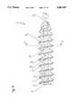
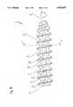
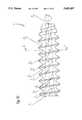
- FIGS. 1A to 1Hrespectively show first through eighth embodiments of a screw according to the invention, in side view;
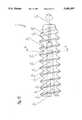
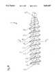
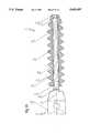
- FIGS. 2A to 2Hshow the embodiments of the screw according to the invention, in accordance with the corresponding FIGS. 1A to 1H, in longitudinal section and with a screwdriver according to the invention inserted therein and shown in a broken view;
- FIGS. 3 to 10show in each case a cross-section of the screw according to the invention, along the line A--A in FIGS. 1A to 1H, in order to illustrate respective design embodiments of a channel wall of the screw according to the invention;
- FIGS. 11 and 12show the same representation as in FIGS. 9 and 10, respectively, with the insertion of only a few reference symbols and the addition of an angle dimension;
- FIGS. 13 to 16show in each case a cross-section of the screw according to the invention, along the line A--A in FIGS. 1A to 1H, in order to illustrate further respective design embodiments of a channel wall of the screw according to the invention.
- the screws according to the invention which are shown in the figuresare made, for example, of a biodegradable material for bone surgery purposes.
- a biodegradable materialfor bone surgery purposes.
- An example of such a material which may be mentioned hereis the commercially available material marketed under the trademark PHUSILINE by the company ArgoMedical AG, CH-6330 Cham, although this does not rule out the use of other biodegradable materials.
- This biodegradable materialis worked to the desired shape in a known manner, for example by injection moulding, hot forming, hot press moulding and similar processes at a temperature suitable for this, which temperature is, in most cases, to be chosen in the range between room temperature and 100° C.
- a screw 1is shown in side view.
- a screw body 2 of the screw 1extends in the direction of a longitudinal axis L of the screw 1 between a proximal end 3 and a distal end 4 of the screw 1 and of the screw body 2.
- An outer surface 5 of the screw body 2is provided with an external thread 6 which is coaxial with respect to the longitudinal axis and is intended for guiding and holding the screw 1 on bone material of a patient.
- the pitch of the external thread 6defines a direction of rotation D about the longitudinal axis L, in which direction the screw or the screw body 2 is screwed in, the distal end 4 of the screw body 2 advancing into the bone material.
- a screw 1 of the type described aboveis shown in longitudinal section in each of FIGS. 2A to 2H.
- a channel 7 which is coaxial with respect to the longitudinal axis Lis provided in the screw body 2.
- This channel 7extends into the area of the distal end 4: in the embodiments according to FIGS. 1A, 1C, 1E and 1G and also 2A, 2C, 2E and 2G right up to the distal end 4, and in the embodiments according to FIGS. 1B, 1D, 1F and 1H and also 2B, 2D, 2F and 2H only as far as the vicinity of the distal end 4.
- a circular cylindrical auxiliary channel 12which is coaxial with respect to the longitudinal axis L and whose role is explained further below.
- the channel 7is open to the outside in order to be able to receive a shaft 8 of a screwdriver 9.
- the shaft 8is shown, in side view, fitted coaxially in the channel 7 of the screw body 2, while the screwdriver 9 is provided with a coaxial grip 10 which is shown in a broken view.
- the shaft 8has a form matching the channel 7 in a complementary manner, which form is explained in greater detail below. With the aid of the grip 10, the shaft 8 of the screwdriver 9 can be introduced into the channel 7 and removed therefrom, and the screwdriver 9 (with the shaft 8 introduced into the channel 7) can be operated in order to turn the screw 1.
- the auxiliary channel 12prevents the shaft 8, when introduced into the channel 7, from acting as a piston and compressing air in the channel 7.
- the auxiliary channel 12can serve, in a manner known, for example from U.S. Pat. No. 4,950,270, as a passage for a guide pin or a guide wire, if the shaft 8 of the screwdriver 9 is correspondingly channelled.
- the channel 7 and the shaft 8have rectilinear generating lines (i.e., generatrice) 18, which are parallel with respect to the longitudinal axis L.
- the channel 7 and the shaft 8can therefore be inscribed in a cylindrical enveloping volume.
- the channel 7 and the shaft 8have rectilinear generating lines 19 which lie obliquely, i.e. at an angle with respect to the longitudinal axis L, with a semi-aperture angle of 2°.
- the channel 7 and the shaft 8can therefore be inscribed in a frustoconical enveloping volume with a semi-aperture angle of 2°.
- the channel 7 and the shaft 8have helical generating lines 20 which in each case lie skew with respect to the longitudinal axis L on a cylinder coaxial to the longitudinal axis L.
- the channel 7 and the shaft 8can therefore be inscribed in a cylindrical enveloping volume.
- the channel 7 and the shaft 8have helical generating lines 21 which in each case lie skew with respect to the longitudinal axis L on a truncated cone coaxial to the longitudinal axis L, with a semi-aperture angle of 2°.
- the channel 7 and the shaft 8can therefore be inscribed in a frustoconical enveloping volume with a semi-aperture angle of 2°.
- FIGS. 3 to 10show embodiments of the channel wall 13, as trace line thereof, in the plane of a respective cross-section of the screw body 2 at right angles to the longitudinal axis L.
- a trace line 14corresponds to the longitudinal axis L
- a trace line 15 to the outer surface 5 of the screw body 2corresponds to the longitudinal axis L
- a trace line 16 to the external thread 6corresponds to the channel wall 13.
- This trace line 17 of the channel wall 13is a closed contour line which is radially symmetrical, in discrete, regular rotary steps, about a center of symmetry formed by the trace line 14 of the longitudinal axis L, namely, in the embodiment according to FIG. 3, in three rotary steps of 120°, in the embodiment according to FIG. 4 in four rotary steps of 90°, in the embodiments according to FIGS. 5 and 10 in eight rotary steps of 45°, and in the embodiments according to FIGS. 6 to 9 in each case in six rotary steps of 60°.
- the form of the trace line 17 of the channel wall 13shows that the channel wall 13 defines, in the channel 7, an axial channel area 22 and a plurality of lobe areas 23 arranged uniformly about the channel area 22, these lobe areas in the embodiment according to FIG. 3 numbering three, in the embodiment according to FIG. 4 numbering four, in the embodiments according to FIGS. 5 and 10 numbering eight, and in the embodiments according to FIGS. 6 to 9 in each case numbering six.
- the channel 7consists essentially of the combination of the axial channel area 22 and the respective lobe areas 23.
- the channel wall 13has a pair of flanks which extend essentially radially outwards starting from the channel area 22.
- a leading flank and a trailing flank 25are defined with reference to the direction of rotation D.
- a trace line 24corresponds to the leading flank and a trace line 25 to the trailing flank.
- the trace lines 24 and 25 of the two flanks in each caseextend as far as a trace line 26 of an end of the lobe area 23 remote from the channel area 22, so that, viewed spatially, the two flanks run together at the end of the lobe area 23 to form an edge.
- the trace lines 24 and 25 of the two flanks in each caseextend into the vicinity of the trace line of that end 26 of the lobe area 23 remote from the channel area 22, but only one of these flanks, namely the leading flank with the trace line 24 in FIGS. 7 and 8, and the trailing flank with the trace line 25 in FIG.
- the lobe area 23ends in a truncated manner and has, in the area of its end, a closure wall with a trace line 27.
- each lobe area 23at least the leading flank with the trace line 24 exhibits, at least in some areas, a form which leads to an increasing extent in the direction of rotation D as the radial distance from the trace line 14 of the longitudinal axis L increases.
- both flanks with the trace lines 24 and 25have a form which leads to an increasing extent in the direction of rotation D over the entire radial length thereof as the radial distance increases.
- the leading flank with the trace line 24has a form which leads, approximately over a radial outer half of its radial length (in other words in the vicinity of the trace line 26 of the end of the lobe area 23), to an increasing extent in the direction of rotation D as the radial distance increases.
- the trailing flank with the trace line 25has, at all times, a form which leads to an increasing extent in the direction of rotation D over its entire radial length as the radial distance increases, but the closure wall with the trace line 27 is also to be taken into consideration, which wall, in the stated direction, leads in the embodiment according to FIG. 8 and does not lead in the embodiments according to FIGS. 7 and 10.
- a surface leading in a predetermined direction of rotation with increasing radial distance from an axisIn a cross-section of the surface at right angles to the axis, two points of a trace line of the surface are considered. Starting from the axis, a first radius is directed to the point nearer the axis and a second radius is directed to the point more remote from the axis. In order to make the first radius congruent with the second radius, a turning is required.
- each lobe area 23tapers towards its end with the trace line 26.
- the two flanks with the trace lines 24 and 25are at a distance from one another which tapers towards the trace line 26 of the end of the lobe area 23 as the radial distance from the longitudinal axis L increases.
- This form of the lobe area 23is obtained by virtue of the fact that, at least in the vicinity of the end of the lobe area 23 with the trace line 26, the leading flank with the trace line 24 is curved concavely with respect to the direction of rotation D, and the trailing flank with the trace line 25 is curved convexly counter to the direction of rotation D.
- each lobe area 23retains an approximately uniform width since the two flanks with the trace lines 24 and 25 are at an approximately constant distance from one another therein.
- the trace line 24 of the leading flankis inclined essentially in a straight line and with respect to the said direction of rotation. This inclination of the leading flank 24 is up to 10° and is preferably about 5°.
- the embodiment according to FIG. 9is represented identically in FIG. 11, and the embodiment according to FIG. 10 is represented identically in FIG. 12, albeit, for reasons of improved clarity, without hatching, and with only a few of the reference symbols, but with an added angle dimension between the trace line 24 of the leading flank and the trace line 28 of a diametral plane passing through the end or through its trace line 26.
- the value of this angleis, for example in the embodiment according to FIGS. 9 and 11, equal to approximately 5°, and, in the embodiment according to FIGS. 10 and 12, equal to approximately 6°.
- FIGS. 13 to 16show embodiments of the channel wall 13, as trace line thereof, in the plane of a respective cross-section of the screw body 2 at right angles to the longitudinal axis L.
- a trace line 14corresponds to the longitudinal axis L
- a trace line 15 to the outer surface 5 of the screw body 2corresponds to the longitudinal axis L
- a trace line 16 to the external thread 6corresponds to the channel wall 13.
- This trace line 17 of the channel wall 13is a closed contour line which is radially symmetrical, in discrete, regular rotary steps, about a center of symmetry formed by the trace line 14 of the longitudinal axis L, namely, in the embodiments shown according to FIGS. 13 to 16 each time in six rotary steps of 60°, which does not exclude other embodiments not shown, for instance in three rotary steps of 120°, in four rotary steps of 90°, in eight rotary steps of 45° etc.
- the form of the trace line 17 of the channel wall 13shows that the channel wall 13 defines, in the channel 7, an axial channel area 22 and a plurality of lobe areas 23 arranged uniformly about the channel area 22, these lobe areas in the embodiment according to FIGS. 13 to 16 in each case numbering six, but in other embodiments not shown possibly numbering three, four, eight etc.
- the channel 7consists essentially of the combination of the axial channel area 22 and the respective lobe areas 23.
- the channel wall 13has a pair of flanks which extend essentially radially outwards starting from the channel area 22.
- a leading flank and a trailing flank 25are defined with reference to the direction of rotation D.
- a trace line 24corresponds to the leading flank and a trace line 25 to the trailing flank.
- the trace lines 24 and 25 of the two flanksin each case extend as far as a trace line 26 of an end of the lobe area 23 remote from the channel area 22, so that, viewed spatially, the two flanks run together at the end of the lobe area 23 to form an edge.
- the trace lines 24 and 25 of the two flanksin each case extend as far as a trace line 26 of an end of the lobe area 23 remote from the channel area 22, so that, viewed spatially, the two flanks run together at the end of the lobe area 23 to form an edge.
- the trace lines 24 and 25 of the two flanksin each case extend into the vicinity of the trace line of that end 26 of the lobe area 23 remote from the channel area 22, but only one of these flanks, namely the trailing flank with the trace line 25, extends right up to the trace line 26 of the end of the lobe area 23, so that, viewed spatially, the lobe area 23 ends in a truncated manner and has, in the area of its end, a closure wall with a trace line 27.
- each lobe area 23is formed asymmetrical in respect of a diametrical plane passing through the longitudinal axis L.
- a sawtooth-like profile(of a radial distance of the contour line 17 from the longitudinal axis L when considered along the contour line 17) with, on the average, a steeper raise of the leading flank 24 and a flatter fall of the trailing flank 25, as shown a section of the contour line 17 which corresponds to the leading flank 24 is formed shorter than a section of the contour line 17 which corresponds to the trailing flank 25.
- each lobe area 23tapers towards its end with the trace line 26.
- the two flanks with the trace lines 24 and 25are at a distance from one another which tapers towards the trace line 26 of the end of the lobe area 23 as the radial distance from the longitudinal axis L increases.
- This form of the lobe area 23is obtained by virtue of the fact that, at least in the vicinity of the end of the lobe area 23 with the trace line 26, the leading flank with the trace line 24 is curved with respect to the direction of rotation D less convexly i.e.
- a planar embodiment of the leading flank with the trace line 24has to be understood as a limiting case in which the convex trace line has an infinitely large radius of curvature. If the two flanks with the trace lines 24 and 25 run together at the end of the lobe area 23 with the trace line 26 to form an edge, this results in a contour line of the trace line 17 of the channel wall 13 having a pointed star-shaped continuous line which is radially symmetrical about the trace line 14 of the longitudinal axis L and has teeth of corresponding number, salient with respect to the direction of rotation D.
- the channel 7has, as in the embodiments according to FIGS. 1A and 2A and also 1B and 2B, generating lines 18 which are rectilinear and parallel with respect to the longitudinal axis L, then the leading flank lies essentially in one plane, and the contour lines or trace lines 17 of the channel wall 13, in two cross-sections of the screw body 2 which are different from one another and at right angles to the longitudinal axis L, are congruent with one another.
- the channel 7has, as in the embodiments according to FIGS. 1C and 2C and also 1D and 2D, generating lines 19 which are rectilinear and lie obliquely with respect to the longitudinal axis L, then the leading flank is tapered in the direction from the proximal end 3 to the distal end 4, and the contour lines or trace lines 17 of the channel wall 13, in two cross-sections of the screw body 2 which are different from one another and at right angles to the longitudinal axis L, are images of one another which can be made congruent by homothetic transformation about the trace line 14 of the longitudinal axis L.
- the channel 7has, as in the embodiments according to FIGS. 1E and 2E and also 1F and 2F, generating lines 20 which are twisted helically about the longitudinal axis L with respect to the direction of rotation D, then the leading flank is also twisted helically about the longitudinal axis L with respect to the direction of rotation D, and the contour lines or trace lines 17 of the channel wall 13, in two cross-sections of the screw body 2 which are different from one another and at right angles to the longitudinal axis L, are congruence images of one another which can be made congruent by simple turning about the trace line 14 of the longitudinal axis L.
- the channel 7has, as in the embodiments according to FIGS. 1G and 2G and also 1H and 2H, generating lines 21 which are twisted helically about the longitudinal axis L with respect to the direction of rotation D and at the same time lie skew with respect to the longitudinal axis L, then the leading flank is also both helically twisted about the longitudinal axis L with respect to the direction of rotation D and tapered in the direction from the proximal end 3 to the distal end 4, and the contour lines or trace lines 17 of the channel wall 13, in two cross-sections of the screw body 2 which are different from one another and at right angles to the longitudinal axis L, are images of one another which can be made congruent by a combination of simple turning and homothetic transformation about the trace line 14 of the longitudinal axis L.
- the pitchis, for example, one turn in 10 cm.
- the semi-aperture angleis up to 10° and preferably about 2°.
- the shaft 8 of the screwdriver 9 for driving a screw 1 into bone material of a patient during bone surgerymust be capable of being introduced into the channel 7 and removed therefrom, the shaft 8 has a form which matches the channel 7 in a complementary manner and which corresponds to the embodiments of the screw described above and, having a contour of corresponding cross-section, can be cylindrical or frustoconical and rectilinear or twisted.
Landscapes
- Health & Medical Sciences (AREA)
- Orthopedic Medicine & Surgery (AREA)
- Surgery (AREA)
- Life Sciences & Earth Sciences (AREA)
- Engineering & Computer Science (AREA)
- Animal Behavior & Ethology (AREA)
- Public Health (AREA)
- Heart & Thoracic Surgery (AREA)
- Medical Informatics (AREA)
- Molecular Biology (AREA)
- Nuclear Medicine, Radiotherapy & Molecular Imaging (AREA)
- General Health & Medical Sciences (AREA)
- Biomedical Technology (AREA)
- Veterinary Medicine (AREA)
- Neurology (AREA)
- General Engineering & Computer Science (AREA)
- Mechanical Engineering (AREA)
- Surgical Instruments (AREA)
- Materials For Medical Uses (AREA)
- Biological Depolymerization Polymers (AREA)
- Compositions Of Macromolecular Compounds (AREA)
Abstract
Description
Claims (20)
Priority Applications (1)
| Application Number | Priority Date | Filing Date | Title |
|---|---|---|---|
| US08/412,307US5695497A (en) | 1994-03-29 | 1995-03-29 | Screw made of biodegradable material for bone surgery purposes, and screwdriver suitable therefor |
Applications Claiming Priority (6)
| Application Number | Priority Date | Filing Date | Title |
|---|---|---|---|
| CH00938/94 | 1994-03-29 | ||
| CH93894 | 1994-03-29 | ||
| US30931194A | 1994-09-20 | 1994-09-20 | |
| CH375794 | 1994-12-12 | ||
| CH03757/94 | 1994-12-12 | ||
| US08/412,307US5695497A (en) | 1994-03-29 | 1995-03-29 | Screw made of biodegradable material for bone surgery purposes, and screwdriver suitable therefor |
Related Parent Applications (1)
| Application Number | Title | Priority Date | Filing Date |
|---|---|---|---|
| US30931194AContinuation-In-Part | 1994-03-29 | 1994-09-20 |
Publications (1)
| Publication Number | Publication Date |
|---|---|
| US5695497Atrue US5695497A (en) | 1997-12-09 |
Family
ID=25686171
Family Applications (1)
| Application Number | Title | Priority Date | Filing Date |
|---|---|---|---|
| US08/412,307Expired - LifetimeUS5695497A (en) | 1994-03-29 | 1995-03-29 | Screw made of biodegradable material for bone surgery purposes, and screwdriver suitable therefor |
Country Status (7)
| Country | Link |
|---|---|
| US (1) | US5695497A (en) |
| EP (1) | EP0674880B1 (en) |
| AT (1) | ATE146063T1 (en) |
| AU (1) | AU689846B2 (en) |
| CA (1) | CA2145449C (en) |
| DE (1) | DE59500060D1 (en) |
| ES (1) | ES2097665T3 (en) |
Cited By (109)
| Publication number | Priority date | Publication date | Assignee | Title |
|---|---|---|---|---|
| US5971987A (en)* | 1998-09-18 | 1999-10-26 | Ethicon, Inc. | Biocompatible absorbable polymer fastener and driver for use in surgical procedures |
| US6096060A (en)* | 1999-05-20 | 2000-08-01 | Linvatec Corporation | Bioabsorbable threaded soft tissue anchor system |
| US6187008B1 (en) | 1999-07-07 | 2001-02-13 | Bristol-Myers Squibb | Device for temporarily fixing bones |
| US6471707B1 (en) | 2001-05-11 | 2002-10-29 | Biomet | Bone screw having bioresorbable proximal shaft portion |
| US6503252B2 (en)* | 2001-02-21 | 2003-01-07 | Henrik Hansson | Bone screw, method for producing the threads thereof and drill for drilling holes therefor |
| US20030065332A1 (en)* | 2001-09-28 | 2003-04-03 | Ethicon, Inc. | Self-tapping resorbable two-piece bone screw |
| US20040102780A1 (en)* | 2002-11-26 | 2004-05-27 | West Hugh S. | Protective devices for use with angled interference screws |
| US20040106950A1 (en)* | 2002-09-12 | 2004-06-03 | Grafton R. Donald | Fully threaded suture anchor with insert-molded suture |
| US20040230195A1 (en)* | 2003-05-14 | 2004-11-18 | Inion Ltd. | Soft-tissue screw |
| US20040243139A1 (en)* | 2003-04-28 | 2004-12-02 | Lewis Derek S. | Multiple screw delivery apparatus |
| US20050087187A1 (en)* | 1999-05-06 | 2005-04-28 | Michael Berthon-Jones | Control of supplied pressure in assisted ventilation |
| US6921402B2 (en)* | 2001-12-27 | 2005-07-26 | Ethicon, Inc. | Polymer-based orthopedic screw and driver system with increased insertion torque tolerance and associated method for making and using same |
| US20060217727A1 (en)* | 2002-06-21 | 2006-09-28 | Chad Munro | Bone screw |
| US20080154314A1 (en)* | 2006-08-16 | 2008-06-26 | Mcdevitt Dennis M | Composite interference screw for attaching a graft ligament to a bone, and other apparatus for making attachments to bone |
| US7455674B2 (en) | 2002-01-31 | 2008-11-25 | Smith & Nephew Plc | High strength bioresorbables containing poly-glycolic acid |
| JP2009534100A (en)* | 2006-04-21 | 2009-09-24 | デボル,インコーポレイテッド | Surgical fixation method and apparatus |
| US7601165B2 (en) | 2006-09-29 | 2009-10-13 | Biomet Sports Medicine, Llc | Method and apparatus for forming a self-locking adjustable suture loop |
| US7604643B2 (en) | 2004-04-06 | 2009-10-20 | Synthes Usa, Llc | Adjustable tool for cannulated fasteners |
| US7608092B1 (en) | 2004-02-20 | 2009-10-27 | Biomet Sports Medicince, LLC | Method and apparatus for performing meniscus repair |
| US7608098B1 (en) | 2004-11-09 | 2009-10-27 | Biomet Sports Medicine, Llc | Bone fixation device |
| US20090319043A1 (en)* | 2007-08-16 | 2009-12-24 | Mcdevitt Dennis | Helicoil interference fixation system for attaching a graft ligament to a bone |
| US20100136648A1 (en)* | 2007-04-18 | 2010-06-03 | Smith & Nephew, Plc | Expansion Moulding of Shape Memory Polymers |
| US20100145448A1 (en)* | 2007-04-19 | 2010-06-10 | Smith & Nephew, Inc. | Graft Fixation |
| US7749250B2 (en) | 2006-02-03 | 2010-07-06 | Biomet Sports Medicine, Llc | Soft tissue repair assembly and associated method |
| US7766920B2 (en) | 2003-11-26 | 2010-08-03 | Synthes Usa, Llc | Cannulated fastener system |
| US20100274266A1 (en)* | 2009-04-22 | 2010-10-28 | Ofir Rimer | Rotary tack |
| US7857830B2 (en) | 2006-02-03 | 2010-12-28 | Biomet Sports Medicine, Llc | Soft tissue repair and conduit device |
| US7905904B2 (en) | 2006-02-03 | 2011-03-15 | Biomet Sports Medicine, Llc | Soft tissue repair device and associated methods |
| US7905903B2 (en) | 2006-02-03 | 2011-03-15 | Biomet Sports Medicine, Llc | Method for tissue fixation |
| US7909851B2 (en) | 2006-02-03 | 2011-03-22 | Biomet Sports Medicine, Llc | Soft tissue repair device and associated methods |
| US7914539B2 (en) | 2004-11-09 | 2011-03-29 | Biomet Sports Medicine, Llc | Tissue fixation device |
| US7959650B2 (en) | 2006-09-29 | 2011-06-14 | Biomet Sports Medicine, Llc | Adjustable knotless loops |
| US20110144751A1 (en)* | 2007-04-19 | 2011-06-16 | Smith & Nephew, Inc | Multi-Modal Shape Memory Polymers |
| WO2011112776A1 (en)* | 2010-03-10 | 2011-09-15 | Smith & Nephew, Inc. | Composite interference screws and drivers |
| US8034090B2 (en) | 2004-11-09 | 2011-10-11 | Biomet Sports Medicine, Llc | Tissue fixation device |
| US8088130B2 (en) | 2006-02-03 | 2012-01-03 | Biomet Sports Medicine, Llc | Method and apparatus for coupling soft tissue to a bone |
| US8118836B2 (en) | 2004-11-05 | 2012-02-21 | Biomet Sports Medicine, Llc | Method and apparatus for coupling soft tissue to a bone |
| US8128658B2 (en) | 2004-11-05 | 2012-03-06 | Biomet Sports Medicine, Llc | Method and apparatus for coupling soft tissue to bone |
| US8137382B2 (en) | 2004-11-05 | 2012-03-20 | Biomet Sports Medicine, Llc | Method and apparatus for coupling anatomical features |
| US8251998B2 (en) | 2006-08-16 | 2012-08-28 | Biomet Sports Medicine, Llc | Chondral defect repair |
| US8298262B2 (en) | 2006-02-03 | 2012-10-30 | Biomet Sports Medicine, Llc | Method for tissue fixation |
| US8303604B2 (en) | 2004-11-05 | 2012-11-06 | Biomet Sports Medicine, Llc | Soft tissue repair device and method |
| US8317825B2 (en) | 2004-11-09 | 2012-11-27 | Biomet Sports Medicine, Llc | Soft tissue conduit device and method |
| US8343227B2 (en) | 2009-05-28 | 2013-01-01 | Biomet Manufacturing Corp. | Knee prosthesis assembly with ligament link |
| US8361113B2 (en) | 2006-02-03 | 2013-01-29 | Biomet Sports Medicine, Llc | Method and apparatus for coupling soft tissue to a bone |
| US8500818B2 (en) | 2006-09-29 | 2013-08-06 | Biomet Manufacturing, Llc | Knee prosthesis assembly with ligament link |
| US8506597B2 (en) | 2011-10-25 | 2013-08-13 | Biomet Sports Medicine, Llc | Method and apparatus for interosseous membrane reconstruction |
| US8562647B2 (en) | 2006-09-29 | 2013-10-22 | Biomet Sports Medicine, Llc | Method and apparatus for securing soft tissue to bone |
| US8562645B2 (en) | 2006-09-29 | 2013-10-22 | Biomet Sports Medicine, Llc | Method and apparatus for forming a self-locking adjustable loop |
| US8574235B2 (en) | 2006-02-03 | 2013-11-05 | Biomet Sports Medicine, Llc | Method for trochanteric reattachment |
| US8579948B2 (en) | 2009-07-01 | 2013-11-12 | Biedermann Technologies Gmbh & Co. Kg | Instruments for use with a bone anchor with plug member |
| US8597327B2 (en) | 2006-02-03 | 2013-12-03 | Biomet Manufacturing, Llc | Method and apparatus for sternal closure |
| US8652172B2 (en) | 2006-02-03 | 2014-02-18 | Biomet Sports Medicine, Llc | Flexible anchors for tissue fixation |
| US8652171B2 (en) | 2006-02-03 | 2014-02-18 | Biomet Sports Medicine, Llc | Method and apparatus for soft tissue fixation |
| US8672969B2 (en) | 2006-09-29 | 2014-03-18 | Biomet Sports Medicine, Llc | Fracture fixation device |
| US8722783B2 (en) | 2006-11-30 | 2014-05-13 | Smith & Nephew, Inc. | Fiber reinforced composite material |
| US8771352B2 (en) | 2011-05-17 | 2014-07-08 | Biomet Sports Medicine, Llc | Method and apparatus for tibial fixation of an ACL graft |
| US8801783B2 (en) | 2006-09-29 | 2014-08-12 | Biomet Sports Medicine, Llc | Prosthetic ligament system for knee joint |
| US8840645B2 (en) | 2004-11-05 | 2014-09-23 | Biomet Sports Medicine, Llc | Method and apparatus for coupling soft tissue to a bone |
| US20140316409A1 (en)* | 2011-07-15 | 2014-10-23 | Smith & Nephew, Inc. | Reducing implant stress zones |
| EP2801331A1 (en)* | 2013-05-10 | 2014-11-12 | Bossard AG | Screw, in particular bone screw for use in surgery |
| US8926637B2 (en) | 2003-06-13 | 2015-01-06 | Covidien Lp | Multiple member interconnect for surgical instrument and absorbable screw fastener |
| US8936621B2 (en) | 2006-02-03 | 2015-01-20 | Biomet Sports Medicine, Llc | Method and apparatus for forming a self-locking adjustable loop |
| US8968364B2 (en) | 2006-02-03 | 2015-03-03 | Biomet Sports Medicine, Llc | Method and apparatus for fixation of an ACL graft |
| US8998949B2 (en) | 2004-11-09 | 2015-04-07 | Biomet Sports Medicine, Llc | Soft tissue conduit device |
| US9017381B2 (en) | 2007-04-10 | 2015-04-28 | Biomet Sports Medicine, Llc | Adjustable knotless loops |
| WO2015077327A1 (en)* | 2013-11-20 | 2015-05-28 | Smith & Nephew, Inc. | Anchor having a controlled driver orientation |
| US9078644B2 (en) | 2006-09-29 | 2015-07-14 | Biomet Sports Medicine, Llc | Fracture fixation device |
| US9120919B2 (en) | 2003-12-23 | 2015-09-01 | Smith & Nephew, Inc. | Tunable segmented polyacetal |
| US9149267B2 (en) | 2006-02-03 | 2015-10-06 | Biomet Sports Medicine, Llc | Method and apparatus for coupling soft tissue to a bone |
| US9155580B2 (en) | 2011-08-25 | 2015-10-13 | Medos International Sarl | Multi-threaded cannulated bone anchors |
| US9155531B2 (en) | 2013-03-15 | 2015-10-13 | Smith & Nephew, Inc. | Miniaturized dual drive open architecture suture anchor |
| US9259217B2 (en) | 2012-01-03 | 2016-02-16 | Biomet Manufacturing, Llc | Suture Button |
| US9265548B2 (en) | 2008-10-30 | 2016-02-23 | DePuy Synthes Products, Inc. | Systems and methods for delivering bone cement to a bone anchor |
| US9271713B2 (en) | 2006-02-03 | 2016-03-01 | Biomet Sports Medicine, Llc | Method and apparatus for tensioning a suture |
| US9271725B2 (en) | 2006-07-18 | 2016-03-01 | Davol, Inc. | Method and apparatus for surgical fastening |
| US9308080B2 (en) | 2010-03-10 | 2016-04-12 | Smith & Nephew Inc. | Composite interference screws and drivers |
| US9314241B2 (en) | 2011-11-10 | 2016-04-19 | Biomet Sports Medicine, Llc | Apparatus for coupling soft tissue to a bone |
| US9357991B2 (en) | 2011-11-03 | 2016-06-07 | Biomet Sports Medicine, Llc | Method and apparatus for stitching tendons |
| US9370350B2 (en) | 2011-11-10 | 2016-06-21 | Biomet Sports Medicine, Llc | Apparatus for coupling soft tissue to a bone |
| US9381013B2 (en) | 2011-11-10 | 2016-07-05 | Biomet Sports Medicine, Llc | Method for coupling soft tissue to a bone |
| US9538998B2 (en) | 2006-02-03 | 2017-01-10 | Biomet Sports Medicine, Llc | Method and apparatus for fracture fixation |
| US9579188B2 (en) | 2010-03-10 | 2017-02-28 | Smith & Nephew, Inc. | Anchor having a controlled driver orientation |
| US9615822B2 (en) | 2014-05-30 | 2017-04-11 | Biomet Sports Medicine, Llc | Insertion tools and method for soft anchor |
| US9700291B2 (en) | 2014-06-03 | 2017-07-11 | Biomet Sports Medicine, Llc | Capsule retractor |
| US9757119B2 (en) | 2013-03-08 | 2017-09-12 | Biomet Sports Medicine, Llc | Visual aid for identifying suture limbs arthroscopically |
| US9775702B2 (en) | 2010-03-10 | 2017-10-03 | Smith & Nephew, Inc. | Composite interference screws and drivers |
| US9801708B2 (en) | 2004-11-05 | 2017-10-31 | Biomet Sports Medicine, Llc | Method and apparatus for coupling soft tissue to a bone |
| US9808298B2 (en) | 2013-04-09 | 2017-11-07 | Smith & Nephew, Inc. | Open-architecture interference screw |
| US9901355B2 (en) | 2011-03-11 | 2018-02-27 | Smith & Nephew, Inc. | Trephine |
| US9918826B2 (en) | 2006-09-29 | 2018-03-20 | Biomet Sports Medicine, Llc | Scaffold for spring ligament repair |
| US9918827B2 (en) | 2013-03-14 | 2018-03-20 | Biomet Sports Medicine, Llc | Scaffold for spring ligament repair |
| US9924934B2 (en) | 2011-06-07 | 2018-03-27 | Smith & Nephew, Inc. | Surgical anchor delivery system |
| US9955980B2 (en) | 2015-02-24 | 2018-05-01 | Biomet Sports Medicine, Llc | Anatomic soft tissue repair |
| US10039543B2 (en) | 2014-08-22 | 2018-08-07 | Biomet Sports Medicine, Llc | Non-sliding soft anchor |
| US10136886B2 (en) | 2013-12-20 | 2018-11-27 | Biomet Sports Medicine, Llc | Knotless soft tissue devices and techniques |
| US10517587B2 (en) | 2006-02-03 | 2019-12-31 | Biomet Sports Medicine, Llc | Method and apparatus for forming a self-locking adjustable loop |
| WO2020169734A1 (en)* | 2019-02-22 | 2020-08-27 | botiss biomaterials GmbH | Implant consisting of bioresorbable material, and method for producing same |
| WO2020169735A1 (en)* | 2019-02-22 | 2020-08-27 | botiss biomaterials GmbH | Corticalis screw consisting of bioresorbable material |
| US10912551B2 (en) | 2015-03-31 | 2021-02-09 | Biomet Sports Medicine, Llc | Suture anchor with soft anchor of electrospun fibers |
| US20210353337A1 (en)* | 2018-02-01 | 2021-11-18 | Genesys Spine | Material directing orthopedic anchor |
| US11259794B2 (en) | 2006-09-29 | 2022-03-01 | Biomet Sports Medicine, Llc | Method for implanting soft tissue |
| US11259792B2 (en) | 2006-02-03 | 2022-03-01 | Biomet Sports Medicine, Llc | Method and apparatus for coupling anatomical features |
| US11311287B2 (en) | 2006-02-03 | 2022-04-26 | Biomet Sports Medicine, Llc | Method for tissue fixation |
| US20230363754A1 (en)* | 2020-10-26 | 2023-11-16 | Smith & Nephew, Inc. | Tissue repair systems and methods of assembly |
| US12096928B2 (en) | 2009-05-29 | 2024-09-24 | Biomet Sports Medicine, Llc | Method and apparatus for coupling soft tissue to a bone |
| US12245759B2 (en) | 2008-08-22 | 2025-03-11 | Biomet Sports Medicine, Llc | Method and apparatus for coupling soft tissue to bone |
| US12329373B2 (en) | 2011-05-02 | 2025-06-17 | Biomet Sports Medicine, Llc | Method and apparatus for soft tissue fixation |
| US12419632B2 (en) | 2008-08-22 | 2025-09-23 | Biomet Sports Medicine, Llc | Method and apparatus for coupling anatomical features |
Families Citing this family (26)
| Publication number | Priority date | Publication date | Assignee | Title |
|---|---|---|---|---|
| US5688285A (en)* | 1995-08-29 | 1997-11-18 | Yamada; Ikufumi | Graft bone fixation tool |
| JPH10165412A (en)* | 1996-12-12 | 1998-06-23 | Asahi Optical Co Ltd | Atlas for fixation |
| DE19751284A1 (en) | 1997-11-19 | 1999-05-27 | Leo Prof Dr Gotzen | Fixation element |
| US6482210B1 (en) | 1998-11-12 | 2002-11-19 | Orthopaedic Biosystems, Ltd., Inc. | Soft tissue/ligament to bone fixation device with inserter |
| US6080161A (en)* | 1999-03-19 | 2000-06-27 | Eaves, Iii; Felmont F. | Fastener and method for bone fixation |
| US6689153B1 (en) | 1999-04-16 | 2004-02-10 | Orthopaedic Biosystems Ltd, Inc. | Methods and apparatus for a coated anchoring device and/or suture |
| FR2803739B1 (en)* | 2000-01-13 | 2002-02-15 | Denis Bertin | THREADED IMPLANT FOR MEDICAL USE |
| US6743233B1 (en) | 2000-08-02 | 2004-06-01 | Orthopaedic Biosystems, Ltd., Inc. | Medical screw and method of installation |
| US20030125749A1 (en)* | 2001-12-27 | 2003-07-03 | Ethicon, Inc. | Cannulated screw and associated driver system |
| GB0208667D0 (en) | 2002-04-16 | 2002-05-29 | Atlantech Medical Devices Ltd | A transverse suspension device |
| US7901404B2 (en) | 2004-01-16 | 2011-03-08 | Arthrocare Corporation | Bone harvesting device and method |
| US7591850B2 (en) | 2005-04-01 | 2009-09-22 | Arthrocare Corporation | Surgical methods for anchoring and implanting tissues |
| US7842042B2 (en) | 2005-05-16 | 2010-11-30 | Arthrocare Corporation | Convergent tunnel guide apparatus and method |
| US8100946B2 (en) | 2005-11-21 | 2012-01-24 | Synthes Usa, Llc | Polyaxial bone anchors with increased angulation |
| US7686838B2 (en) | 2006-11-09 | 2010-03-30 | Arthrocare Corporation | External bullet anchor apparatus and method for use in surgical repair of ligament or tendon |
| PL2170192T3 (en) | 2007-07-20 | 2011-07-29 | Synthes Gmbh | Polyaxial bone fixation element |
| US9439681B2 (en) | 2007-07-20 | 2016-09-13 | DePuy Synthes Products, Inc. | Polyaxial bone fixation element |
| EP2355725B1 (en) | 2008-09-05 | 2017-03-08 | Synthes GmbH | Bone fixation assembly |
| JP5815407B2 (en) | 2008-09-12 | 2015-11-17 | ジンテス ゲゼルシャフト ミット ベシュレンクテル ハフツング | Spinal stabilization and guided fixation system |
| KR20110081208A (en) | 2008-09-29 | 2011-07-13 | 신세스 게엠바하 | Multi-Axis Bottom-Loading Screw and Rod Assemblies |
| CA2742399A1 (en) | 2008-11-03 | 2010-06-03 | Dustin M. Harvey | Uni-planar bone fixation assembly |
| KR20120013312A (en) | 2009-04-15 | 2012-02-14 | 신세스 게엠바하 | Orthodontic Connectors for Spinal Structures |
| CA2764841A1 (en) | 2009-06-17 | 2010-12-23 | Synthes Usa, Llc | Revision connector for spinal constructs |
| US8449612B2 (en) | 2009-11-16 | 2013-05-28 | Arthrocare Corporation | Graft pulley and methods of use |
| EP2596758A1 (en) | 2011-11-24 | 2013-05-29 | Sysorb GmbH | Bone screw |
| CN104972425A (en)* | 2015-06-24 | 2015-10-14 | 李洁梅 | Screwdriver bit |
Citations (7)
| Publication number | Priority date | Publication date | Assignee | Title |
|---|---|---|---|---|
| GB2022482A (en)* | 1978-06-07 | 1979-12-19 | Fenton J W | Torque drive coupling |
| DE8804456U1 (en)* | 1988-04-02 | 1988-06-01 | Aesculap-Werke Ag Vormals Jetter & Scheerer, 7200 Tuttlingen | Bone screw |
| US5139499A (en)* | 1989-02-06 | 1992-08-18 | American Cyanamid Company | Screw and driver |
| EP0502698A1 (en)* | 1991-03-05 | 1992-09-09 | Linvatec Corporation | Bioabsorbable interference bone fixation screw |
| US5169400A (en)* | 1988-04-02 | 1992-12-08 | Aesculap Ag | Bone screw |
| US5269209A (en)* | 1992-10-20 | 1993-12-14 | Baker David R | Curvilinear drive screwdriver and screw |
| US5364400A (en)* | 1992-02-14 | 1994-11-15 | American Cyanamid Co. | Interference implant |
Family Cites Families (1)
| Publication number | Priority date | Publication date | Assignee | Title |
|---|---|---|---|---|
| US4037514A (en)* | 1976-02-23 | 1977-07-26 | Juan Andres Lliteras | High torque fastener head |
- 1995
- 1995-03-17AUAU14923/95Apatent/AU689846B2/ennot_activeCeased
- 1995-03-22EPEP95200700Apatent/EP0674880B1/ennot_activeExpired - Lifetime
- 1995-03-22ATAT95200700Tpatent/ATE146063T1/ennot_activeIP Right Cessation
- 1995-03-22ESES95200700Tpatent/ES2097665T3/ennot_activeExpired - Lifetime
- 1995-03-22DEDE59500060Tpatent/DE59500060D1/ennot_activeExpired - Lifetime
- 1995-03-24CACA002145449Apatent/CA2145449C/ennot_activeExpired - Fee Related
- 1995-03-29USUS08/412,307patent/US5695497A/ennot_activeExpired - Lifetime
Patent Citations (7)
| Publication number | Priority date | Publication date | Assignee | Title |
|---|---|---|---|---|
| GB2022482A (en)* | 1978-06-07 | 1979-12-19 | Fenton J W | Torque drive coupling |
| DE8804456U1 (en)* | 1988-04-02 | 1988-06-01 | Aesculap-Werke Ag Vormals Jetter & Scheerer, 7200 Tuttlingen | Bone screw |
| US5169400A (en)* | 1988-04-02 | 1992-12-08 | Aesculap Ag | Bone screw |
| US5139499A (en)* | 1989-02-06 | 1992-08-18 | American Cyanamid Company | Screw and driver |
| EP0502698A1 (en)* | 1991-03-05 | 1992-09-09 | Linvatec Corporation | Bioabsorbable interference bone fixation screw |
| US5364400A (en)* | 1992-02-14 | 1994-11-15 | American Cyanamid Co. | Interference implant |
| US5269209A (en)* | 1992-10-20 | 1993-12-14 | Baker David R | Curvilinear drive screwdriver and screw |
Cited By (273)
| Publication number | Priority date | Publication date | Assignee | Title |
|---|---|---|---|---|
| US5971987A (en)* | 1998-09-18 | 1999-10-26 | Ethicon, Inc. | Biocompatible absorbable polymer fastener and driver for use in surgical procedures |
| US20050087187A1 (en)* | 1999-05-06 | 2005-04-28 | Michael Berthon-Jones | Control of supplied pressure in assisted ventilation |
| US6096060A (en)* | 1999-05-20 | 2000-08-01 | Linvatec Corporation | Bioabsorbable threaded soft tissue anchor system |
| US6187008B1 (en) | 1999-07-07 | 2001-02-13 | Bristol-Myers Squibb | Device for temporarily fixing bones |
| US6503252B2 (en)* | 2001-02-21 | 2003-01-07 | Henrik Hansson | Bone screw, method for producing the threads thereof and drill for drilling holes therefor |
| US6471707B1 (en) | 2001-05-11 | 2002-10-29 | Biomet | Bone screw having bioresorbable proximal shaft portion |
| US20030065332A1 (en)* | 2001-09-28 | 2003-04-03 | Ethicon, Inc. | Self-tapping resorbable two-piece bone screw |
| US6916321B2 (en) | 2001-09-28 | 2005-07-12 | Ethicon, Inc. | Self-tapping resorbable two-piece bone screw |
| US7708767B2 (en) | 2001-12-27 | 2010-05-04 | Ethicon, Inc. | Polymer-based orthopedic screw and driver system with increased insertion torque tolerance and associated method for making and using same |
| US20050216016A1 (en)* | 2001-12-27 | 2005-09-29 | Contiliano Joseph H | Polymer-based orthopedic screw and driver system with increased insertion torque tolerance and associated method for making and using same |
| US6921402B2 (en)* | 2001-12-27 | 2005-07-26 | Ethicon, Inc. | Polymer-based orthopedic screw and driver system with increased insertion torque tolerance and associated method for making and using same |
| US7455674B2 (en) | 2002-01-31 | 2008-11-25 | Smith & Nephew Plc | High strength bioresorbables containing poly-glycolic acid |
| US20060217727A1 (en)* | 2002-06-21 | 2006-09-28 | Chad Munro | Bone screw |
| US7883528B2 (en)* | 2002-09-12 | 2011-02-08 | Arthrex, Inc. | Fully threaded suture anchor with insert-molded suture |
| US20040106950A1 (en)* | 2002-09-12 | 2004-06-03 | Grafton R. Donald | Fully threaded suture anchor with insert-molded suture |
| US7235078B2 (en)* | 2002-11-26 | 2007-06-26 | Hs West Investments Llc | Protective devices for use with angled interference screws |
| US20040102780A1 (en)* | 2002-11-26 | 2004-05-27 | West Hugh S. | Protective devices for use with angled interference screws |
| US20040243139A1 (en)* | 2003-04-28 | 2004-12-02 | Lewis Derek S. | Multiple screw delivery apparatus |
| US7461574B2 (en) | 2003-04-28 | 2008-12-09 | Biomet Microfixation, Llc | Multiple screw delivery apparatus |
| US20040230195A1 (en)* | 2003-05-14 | 2004-11-18 | Inion Ltd. | Soft-tissue screw |
| US8926637B2 (en) | 2003-06-13 | 2015-01-06 | Covidien Lp | Multiple member interconnect for surgical instrument and absorbable screw fastener |
| US9987010B2 (en) | 2003-06-13 | 2018-06-05 | Covidien Lp | Multiple member interconnect for surgical instrument and absorbable screw fastener |
| US8282651B2 (en) | 2003-11-26 | 2012-10-09 | Synthes Usa, Llc | Cannulated fastener system |
| US7766920B2 (en) | 2003-11-26 | 2010-08-03 | Synthes Usa, Llc | Cannulated fastener system |
| US9120919B2 (en) | 2003-12-23 | 2015-09-01 | Smith & Nephew, Inc. | Tunable segmented polyacetal |
| US7608092B1 (en) | 2004-02-20 | 2009-10-27 | Biomet Sports Medicince, LLC | Method and apparatus for performing meniscus repair |
| US8221454B2 (en) | 2004-02-20 | 2012-07-17 | Biomet Sports Medicine, Llc | Apparatus for performing meniscus repair |
| US8628537B2 (en) | 2004-04-06 | 2014-01-14 | DePuy Synthes Products, LLC | Adjustable tool for cannulated fasteners |
| US7604643B2 (en) | 2004-04-06 | 2009-10-20 | Synthes Usa, Llc | Adjustable tool for cannulated fasteners |
| US10265064B2 (en) | 2004-11-05 | 2019-04-23 | Biomet Sports Medicine, Llc | Soft tissue repair device and method |
| US8303604B2 (en) | 2004-11-05 | 2012-11-06 | Biomet Sports Medicine, Llc | Soft tissue repair device and method |
| US8128658B2 (en) | 2004-11-05 | 2012-03-06 | Biomet Sports Medicine, Llc | Method and apparatus for coupling soft tissue to bone |
| US8118836B2 (en) | 2004-11-05 | 2012-02-21 | Biomet Sports Medicine, Llc | Method and apparatus for coupling soft tissue to a bone |
| US8137382B2 (en) | 2004-11-05 | 2012-03-20 | Biomet Sports Medicine, Llc | Method and apparatus for coupling anatomical features |
| US8840645B2 (en) | 2004-11-05 | 2014-09-23 | Biomet Sports Medicine, Llc | Method and apparatus for coupling soft tissue to a bone |
| US9801708B2 (en) | 2004-11-05 | 2017-10-31 | Biomet Sports Medicine, Llc | Method and apparatus for coupling soft tissue to a bone |
| US11109857B2 (en) | 2004-11-05 | 2021-09-07 | Biomet Sports Medicine, Llc | Soft tissue repair device and method |
| US9504460B2 (en) | 2004-11-05 | 2016-11-29 | Biomet Sports Medicine, LLC. | Soft tissue repair device and method |
| US8551140B2 (en) | 2004-11-05 | 2013-10-08 | Biomet Sports Medicine, Llc | Method and apparatus for coupling soft tissue to bone |
| US9572655B2 (en) | 2004-11-05 | 2017-02-21 | Biomet Sports Medicine, Llc | Method and apparatus for coupling soft tissue to a bone |
| US7914539B2 (en) | 2004-11-09 | 2011-03-29 | Biomet Sports Medicine, Llc | Tissue fixation device |
| US8034090B2 (en) | 2004-11-09 | 2011-10-11 | Biomet Sports Medicine, Llc | Tissue fixation device |
| US8317825B2 (en) | 2004-11-09 | 2012-11-27 | Biomet Sports Medicine, Llc | Soft tissue conduit device and method |
| US7608098B1 (en) | 2004-11-09 | 2009-10-27 | Biomet Sports Medicine, Llc | Bone fixation device |
| US8998949B2 (en) | 2004-11-09 | 2015-04-07 | Biomet Sports Medicine, Llc | Soft tissue conduit device |
| US10675073B2 (en) | 2006-02-03 | 2020-06-09 | Biomet Sports Medicine, Llc | Method and apparatus for sternal closure |
| US10603029B2 (en) | 2006-02-03 | 2020-03-31 | Biomet Sports Medicine, Llc | Method and apparatus for coupling soft tissue to bone |
| US8088130B2 (en) | 2006-02-03 | 2012-01-03 | Biomet Sports Medicine, Llc | Method and apparatus for coupling soft tissue to a bone |
| US12096931B2 (en) | 2006-02-03 | 2024-09-24 | Biomet Sports Medicine, Llc | Method and apparatus for coupling soft tissue to a bone |
| US8273106B2 (en) | 2006-02-03 | 2012-09-25 | Biomet Sports Medicine, Llc | Soft tissue repair and conduit device |
| US12064101B2 (en) | 2006-02-03 | 2024-08-20 | Biomet Sports Medicine, Llc | Method and apparatus for forming a self-locking adjustable loop |
| US8292921B2 (en) | 2006-02-03 | 2012-10-23 | Biomet Sports Medicine, Llc | Soft tissue repair device and associated methods |
| US8298262B2 (en) | 2006-02-03 | 2012-10-30 | Biomet Sports Medicine, Llc | Method for tissue fixation |
| US11998185B2 (en) | 2006-02-03 | 2024-06-04 | Biomet Sports Medicine, Llc | Method and apparatus for coupling soft tissue to a bone |
| US8932331B2 (en) | 2006-02-03 | 2015-01-13 | Biomet Sports Medicine, Llc | Method and apparatus for coupling soft tissue to bone |
| US11819205B2 (en) | 2006-02-03 | 2023-11-21 | Biomet Sports Medicine, Llc | Soft tissue repair device and associated methods |
| US8337525B2 (en) | 2006-02-03 | 2012-12-25 | Biomet Sports Medicine, Llc | Soft tissue repair device and associated methods |
| US11786236B2 (en) | 2006-02-03 | 2023-10-17 | Biomet Sports Medicine, Llc | Method and apparatus for coupling anatomical features |
| US8361113B2 (en) | 2006-02-03 | 2013-01-29 | Biomet Sports Medicine, Llc | Method and apparatus for coupling soft tissue to a bone |
| US8409253B2 (en) | 2006-02-03 | 2013-04-02 | Biomet Sports Medicine, Llc | Soft tissue repair assembly and associated method |
| US11730464B2 (en) | 2006-02-03 | 2023-08-22 | Biomet Sports Medicine, Llc | Soft tissue repair assembly and associated method |
| US11723648B2 (en) | 2006-02-03 | 2023-08-15 | Biomet Sports Medicine, Llc | Method and apparatus for soft tissue fixation |
| US11617572B2 (en) | 2006-02-03 | 2023-04-04 | Biomet Sports Medicine, Llc | Soft tissue repair device and associated methods |
| US7909851B2 (en) | 2006-02-03 | 2011-03-22 | Biomet Sports Medicine, Llc | Soft tissue repair device and associated methods |
| US11589859B2 (en) | 2006-02-03 | 2023-02-28 | Biomet Sports Medicine, Llc | Method and apparatus for coupling soft tissue to bone |
| US11471147B2 (en) | 2006-02-03 | 2022-10-18 | Biomet Sports Medicine, Llc | Method and apparatus for coupling soft tissue to a bone |
| US8574235B2 (en) | 2006-02-03 | 2013-11-05 | Biomet Sports Medicine, Llc | Method for trochanteric reattachment |
| US10987099B2 (en) | 2006-02-03 | 2021-04-27 | Biomet Sports Medicine, Llc | Method for tissue fixation |
| US8597327B2 (en) | 2006-02-03 | 2013-12-03 | Biomet Manufacturing, Llc | Method and apparatus for sternal closure |
| US8608777B2 (en) | 2006-02-03 | 2013-12-17 | Biomet Sports Medicine | Method and apparatus for coupling soft tissue to a bone |
| US7905903B2 (en) | 2006-02-03 | 2011-03-15 | Biomet Sports Medicine, Llc | Method for tissue fixation |
| US8632569B2 (en) | 2006-02-03 | 2014-01-21 | Biomet Sports Medicine, Llc | Soft tissue repair device and associated methods |
| US8652172B2 (en) | 2006-02-03 | 2014-02-18 | Biomet Sports Medicine, Llc | Flexible anchors for tissue fixation |
| US8652171B2 (en) | 2006-02-03 | 2014-02-18 | Biomet Sports Medicine, Llc | Method and apparatus for soft tissue fixation |
| US11317907B2 (en) | 2006-02-03 | 2022-05-03 | Biomet Sports Medicine, Llc | Method and apparatus for forming a self-locking adjustable loop |
| US11311287B2 (en) | 2006-02-03 | 2022-04-26 | Biomet Sports Medicine, Llc | Method for tissue fixation |
| US8721684B2 (en) | 2006-02-03 | 2014-05-13 | Biomet Sports Medicine, Llc | Method and apparatus for coupling anatomical features |
| US11284884B2 (en) | 2006-02-03 | 2022-03-29 | Biomet Sports Medicine, Llc | Method and apparatus for coupling soft tissue to a bone |
| US8771316B2 (en) | 2006-02-03 | 2014-07-08 | Biomet Sports Medicine, Llc | Method and apparatus for coupling anatomical features |
| US11259792B2 (en) | 2006-02-03 | 2022-03-01 | Biomet Sports Medicine, Llc | Method and apparatus for coupling anatomical features |
| US11116495B2 (en) | 2006-02-03 | 2021-09-14 | Biomet Sports Medicine, Llc | Soft tissue repair assembly and associated method |
| US7905904B2 (en) | 2006-02-03 | 2011-03-15 | Biomet Sports Medicine, Llc | Soft tissue repair device and associated methods |
| US11065103B2 (en) | 2006-02-03 | 2021-07-20 | Biomet Sports Medicine, Llc | Method and apparatus for fixation of an ACL graft |
| US9561025B2 (en) | 2006-02-03 | 2017-02-07 | Biomet Sports Medicine, Llc | Soft tissue repair device and associated methods |
| US9538998B2 (en) | 2006-02-03 | 2017-01-10 | Biomet Sports Medicine, Llc | Method and apparatus for fracture fixation |
| US9622736B2 (en) | 2006-02-03 | 2017-04-18 | Biomet Sports Medicine, Llc | Soft tissue repair device and associated methods |
| US11039826B2 (en) | 2006-02-03 | 2021-06-22 | Biomet Sports Medicine, Llc | Method and apparatus for forming a self-locking adjustable loop |
| US11446019B2 (en) | 2006-02-03 | 2022-09-20 | Biomet Sports Medicine, Llc | Method and apparatus for coupling soft tissue to a bone |
| US9763656B2 (en) | 2006-02-03 | 2017-09-19 | Biomet Sports Medicine, Llc | Method and apparatus for soft tissue fixation |
| US11896210B2 (en) | 2006-02-03 | 2024-02-13 | Biomet Sports Medicine, Llc | Method and apparatus for coupling soft tissue to a bone |
| US8936621B2 (en) | 2006-02-03 | 2015-01-20 | Biomet Sports Medicine, Llc | Method and apparatus for forming a self-locking adjustable loop |
| US10973507B2 (en) | 2006-02-03 | 2021-04-13 | Biomet Sports Medicine, Llc | Method and apparatus for coupling soft tissue to a bone |
| US8968364B2 (en) | 2006-02-03 | 2015-03-03 | Biomet Sports Medicine, Llc | Method and apparatus for fixation of an ACL graft |
| US10932770B2 (en) | 2006-02-03 | 2021-03-02 | Biomet Sports Medicine, Llc | Soft tissue repair device and associated methods |
| US9603591B2 (en) | 2006-02-03 | 2017-03-28 | Biomet Sports Medicine, Llc | Flexible anchors for tissue fixation |
| US9532777B2 (en) | 2006-02-03 | 2017-01-03 | Biomet Sports Medicine, Llc | Method and apparatus for coupling soft tissue to a bone |
| US9510821B2 (en) | 2006-02-03 | 2016-12-06 | Biomet Sports Medicine, Llc | Method and apparatus for coupling anatomical features |
| US9510819B2 (en) | 2006-02-03 | 2016-12-06 | Biomet Sports Medicine, Llc | Soft tissue repair device and associated methods |
| US10729430B2 (en) | 2006-02-03 | 2020-08-04 | Biomet Sports Medicine, Llc | Method and apparatus for coupling soft tissue to a bone |
| US9005287B2 (en) | 2006-02-03 | 2015-04-14 | Biomet Sports Medicine, Llc | Method for bone reattachment |
| US10729421B2 (en) | 2006-02-03 | 2020-08-04 | Biomet Sports Medicine, Llc | Method and apparatus for soft tissue fixation |
| US10716557B2 (en) | 2006-02-03 | 2020-07-21 | Biomet Sports Medicine, Llc | Method and apparatus for coupling anatomical features |
| US10702259B2 (en) | 2006-02-03 | 2020-07-07 | Biomet Sports Medicine, Llc | Soft tissue repair assembly and associated method |
| US7749250B2 (en) | 2006-02-03 | 2010-07-06 | Biomet Sports Medicine, Llc | Soft tissue repair assembly and associated method |
| US9149267B2 (en) | 2006-02-03 | 2015-10-06 | Biomet Sports Medicine, Llc | Method and apparatus for coupling soft tissue to a bone |
| US10695052B2 (en) | 2006-02-03 | 2020-06-30 | Biomet Sports Medicine, Llc | Method and apparatus for coupling soft tissue to a bone |
| US10687803B2 (en) | 2006-02-03 | 2020-06-23 | Biomet Sports Medicine, Llc | Method and apparatus for coupling soft tissue to a bone |
| US9173651B2 (en) | 2006-02-03 | 2015-11-03 | Biomet Sports Medicine, Llc | Soft tissue repair device and associated methods |
| US9642661B2 (en) | 2006-02-03 | 2017-05-09 | Biomet Sports Medicine, Llc | Method and Apparatus for Sternal Closure |
| US7857830B2 (en) | 2006-02-03 | 2010-12-28 | Biomet Sports Medicine, Llc | Soft tissue repair and conduit device |
| US10595851B2 (en) | 2006-02-03 | 2020-03-24 | Biomet Sports Medicine, Llc | Method and apparatus for coupling soft tissue to a bone |
| US10542967B2 (en) | 2006-02-03 | 2020-01-28 | Biomet Sports Medicine, Llc | Method and apparatus for coupling soft tissue to a bone |
| US9271713B2 (en) | 2006-02-03 | 2016-03-01 | Biomet Sports Medicine, Llc | Method and apparatus for tensioning a suture |
| US9498204B2 (en) | 2006-02-03 | 2016-11-22 | Biomet Sports Medicine, Llc | Method and apparatus for coupling anatomical features |
| US10517587B2 (en) | 2006-02-03 | 2019-12-31 | Biomet Sports Medicine, Llc | Method and apparatus for forming a self-locking adjustable loop |
| US10441264B2 (en) | 2006-02-03 | 2019-10-15 | Biomet Sports Medicine, Llc | Soft tissue repair assembly and associated method |
| US10398428B2 (en) | 2006-02-03 | 2019-09-03 | Biomet Sports Medicine, Llc | Method and apparatus for coupling anatomical features |
| US10321906B2 (en) | 2006-02-03 | 2019-06-18 | Biomet Sports Medicine, Llc | Method for tissue fixation |
| US10251637B2 (en) | 2006-02-03 | 2019-04-09 | Biomet Sports Medicine, Llc | Soft tissue repair device and associated methods |
| US9492158B2 (en) | 2006-02-03 | 2016-11-15 | Biomet Sports Medicine, Llc | Method and apparatus for coupling soft tissue to a bone |
| US10154837B2 (en) | 2006-02-03 | 2018-12-18 | Biomet Sports Medicine, Llc | Method and apparatus for coupling soft tissue to a bone |
| US10098629B2 (en) | 2006-02-03 | 2018-10-16 | Biomet Sports Medicine, Llc | Method and apparatus for coupling soft tissue to a bone |
| US10092288B2 (en) | 2006-02-03 | 2018-10-09 | Biomet Sports Medicine, Llc | Method and apparatus for coupling soft tissue to a bone |
| US9402621B2 (en) | 2006-02-03 | 2016-08-02 | Biomet Sports Medicine, LLC. | Method for tissue fixation |
| US10022118B2 (en) | 2006-02-03 | 2018-07-17 | Biomet Sports Medicine, Llc | Method and apparatus for coupling soft tissue to a bone |
| US9414833B2 (en) | 2006-02-03 | 2016-08-16 | Biomet Sports Medicine, Llc | Soft tissue repair assembly and associated method |
| US10004588B2 (en) | 2006-02-03 | 2018-06-26 | Biomet Sports Medicine, Llc | Method and apparatus for fixation of an ACL graft |
| US10004489B2 (en) | 2006-02-03 | 2018-06-26 | Biomet Sports Medicine, Llc | Method and apparatus for coupling soft tissue to a bone |
| US9993241B2 (en) | 2006-02-03 | 2018-06-12 | Biomet Sports Medicine, Llc | Method and apparatus for forming a self-locking adjustable loop |
| US9468433B2 (en) | 2006-02-03 | 2016-10-18 | Biomet Sports Medicine, Llc | Method and apparatus for forming a self-locking adjustable loop |
| US9801620B2 (en) | 2006-02-03 | 2017-10-31 | Biomet Sports Medicine, Llc | Method and apparatus for coupling soft tissue to bone |
| US8979874B2 (en) | 2006-04-21 | 2015-03-17 | Davol, Inc. | Method and apparatus for surgical fastening |
| JP2009534100A (en)* | 2006-04-21 | 2009-09-24 | デボル,インコーポレイテッド | Surgical fixation method and apparatus |
| JP2013056164A (en)* | 2006-04-21 | 2013-03-28 | Davol Inc | Method and apparatus for surgical fastening |
| US9271725B2 (en) | 2006-07-18 | 2016-03-01 | Davol, Inc. | Method and apparatus for surgical fastening |
| US20190099255A1 (en)* | 2006-08-16 | 2019-04-04 | Smith & Nephew, Inc. | Helicoil interference fixation system for attaching a graft ligament to a bone |
| US10820983B2 (en)* | 2006-08-16 | 2020-11-03 | Healicoil, Inc. | Helicoil interference fixation system for attaching a graft ligament to a bone |
| US8992612B2 (en) | 2006-08-16 | 2015-03-31 | Smith & Nephew, Inc. | Helicoil interference fixation system for attaching a graft ligament to a bone |
| US20160374794A1 (en)* | 2006-08-16 | 2016-12-29 | Smith & Nephew, Inc. | Helicoil Interference Fixation System For Attaching a Graft Ligament to a Bone |
| US20080154314A1 (en)* | 2006-08-16 | 2008-06-26 | Mcdevitt Dennis M | Composite interference screw for attaching a graft ligament to a bone, and other apparatus for making attachments to bone |
| US8777956B2 (en) | 2006-08-16 | 2014-07-15 | Biomet Sports Medicine, Llc | Chondral defect repair |
| US8251998B2 (en) | 2006-08-16 | 2012-08-28 | Biomet Sports Medicine, Llc | Chondral defect repair |
| US7658751B2 (en) | 2006-09-29 | 2010-02-09 | Biomet Sports Medicine, Llc | Method for implanting soft tissue |
| US8562647B2 (en) | 2006-09-29 | 2013-10-22 | Biomet Sports Medicine, Llc | Method and apparatus for securing soft tissue to bone |
| US10349931B2 (en) | 2006-09-29 | 2019-07-16 | Biomet Sports Medicine, Llc | Fracture fixation device |
| US10398430B2 (en) | 2006-09-29 | 2019-09-03 | Biomet Sports Medicine, Llc | Method for implanting soft tissue |
| US9539003B2 (en) | 2006-09-29 | 2017-01-10 | Biomet Sports Medicine, LLC. | Method and apparatus for forming a self-locking adjustable loop |
| US10517714B2 (en) | 2006-09-29 | 2019-12-31 | Biomet Sports Medicine, Llc | Ligament system for knee joint |
| US9681940B2 (en) | 2006-09-29 | 2017-06-20 | Biomet Sports Medicine, Llc | Ligament system for knee joint |
| US8231654B2 (en) | 2006-09-29 | 2012-07-31 | Biomet Sports Medicine, Llc | Adjustable knotless loops |
| US10610217B2 (en) | 2006-09-29 | 2020-04-07 | Biomet Sports Medicine, Llc | Method and apparatus for forming a self-locking adjustable loop |
| US9724090B2 (en) | 2006-09-29 | 2017-08-08 | Biomet Manufacturing, Llc | Method and apparatus for attaching soft tissue to bone |
| US7959650B2 (en) | 2006-09-29 | 2011-06-14 | Biomet Sports Medicine, Llc | Adjustable knotless loops |
| US9486211B2 (en) | 2006-09-29 | 2016-11-08 | Biomet Sports Medicine, Llc | Method for implanting soft tissue |
| US10695045B2 (en) | 2006-09-29 | 2020-06-30 | Biomet Sports Medicine, Llc | Method and apparatus for attaching soft tissue to bone |
| US8500818B2 (en) | 2006-09-29 | 2013-08-06 | Biomet Manufacturing, Llc | Knee prosthesis assembly with ligament link |
| US11672527B2 (en) | 2006-09-29 | 2023-06-13 | Biomet Sports Medicine, Llc | Method for implanting soft tissue |
| US9788876B2 (en) | 2006-09-29 | 2017-10-17 | Biomet Sports Medicine, Llc | Fracture fixation device |
| US10743925B2 (en) | 2006-09-29 | 2020-08-18 | Biomet Sports Medicine, Llc | Fracture fixation device |
| US10004493B2 (en) | 2006-09-29 | 2018-06-26 | Biomet Sports Medicine, Llc | Method for implanting soft tissue |
| US8562645B2 (en) | 2006-09-29 | 2013-10-22 | Biomet Sports Medicine, Llc | Method and apparatus for forming a self-locking adjustable loop |
| US11376115B2 (en) | 2006-09-29 | 2022-07-05 | Biomet Sports Medicine, Llc | Prosthetic ligament system for knee joint |
| US8672968B2 (en) | 2006-09-29 | 2014-03-18 | Biomet Sports Medicine, Llc | Method for implanting soft tissue |
| US9078644B2 (en) | 2006-09-29 | 2015-07-14 | Biomet Sports Medicine, Llc | Fracture fixation device |
| US9833230B2 (en) | 2006-09-29 | 2017-12-05 | Biomet Sports Medicine, Llc | Fracture fixation device |
| US7601165B2 (en) | 2006-09-29 | 2009-10-13 | Biomet Sports Medicine, Llc | Method and apparatus for forming a self-locking adjustable suture loop |
| US8672969B2 (en) | 2006-09-29 | 2014-03-18 | Biomet Sports Medicine, Llc | Fracture fixation device |
| US9918826B2 (en) | 2006-09-29 | 2018-03-20 | Biomet Sports Medicine, Llc | Scaffold for spring ligament repair |
| US10835232B2 (en) | 2006-09-29 | 2020-11-17 | Biomet Sports Medicine, Llc | Fracture fixation device |
| US11259794B2 (en) | 2006-09-29 | 2022-03-01 | Biomet Sports Medicine, Llc | Method for implanting soft tissue |
| US9414925B2 (en) | 2006-09-29 | 2016-08-16 | Biomet Manufacturing, Llc | Method of implanting a knee prosthesis assembly with a ligament link |
| US8801783B2 (en) | 2006-09-29 | 2014-08-12 | Biomet Sports Medicine, Llc | Prosthetic ligament system for knee joint |
| US11096684B2 (en) | 2006-09-29 | 2021-08-24 | Biomet Sports Medicine, Llc | Method and apparatus for forming a self-locking adjustable loop |
| US8722783B2 (en) | 2006-11-30 | 2014-05-13 | Smith & Nephew, Inc. | Fiber reinforced composite material |
| US11612391B2 (en) | 2007-01-16 | 2023-03-28 | Biomet Sports Medicine, Llc | Soft tissue repair device and associated methods |
| US9861351B2 (en) | 2007-04-10 | 2018-01-09 | Biomet Sports Medicine, Llc | Adjustable knotless loops |
| US10729423B2 (en) | 2007-04-10 | 2020-08-04 | Biomet Sports Medicine, Llc | Adjustable knotless loops |
| US9017381B2 (en) | 2007-04-10 | 2015-04-28 | Biomet Sports Medicine, Llc | Adjustable knotless loops |
| US11185320B2 (en) | 2007-04-10 | 2021-11-30 | Biomet Sports Medicine, Llc | Adjustable knotless loops |
| US12303122B2 (en) | 2007-04-10 | 2025-05-20 | Biomet Sports Medicine, Llc | Adjustable knotless loops |
| US9815240B2 (en) | 2007-04-18 | 2017-11-14 | Smith & Nephew, Inc. | Expansion moulding of shape memory polymers |
| US20100136648A1 (en)* | 2007-04-18 | 2010-06-03 | Smith & Nephew, Plc | Expansion Moulding of Shape Memory Polymers |
| US9000066B2 (en) | 2007-04-19 | 2015-04-07 | Smith & Nephew, Inc. | Multi-modal shape memory polymers |
| US9770534B2 (en) | 2007-04-19 | 2017-09-26 | Smith & Nephew, Inc. | Graft fixation |
| US20110144751A1 (en)* | 2007-04-19 | 2011-06-16 | Smith & Nephew, Inc | Multi-Modal Shape Memory Polymers |
| US20100145448A1 (en)* | 2007-04-19 | 2010-06-10 | Smith & Nephew, Inc. | Graft Fixation |
| US9308293B2 (en) | 2007-04-19 | 2016-04-12 | Smith & Nephew, Inc. | Multi-modal shape memory polymers |
| US20090319043A1 (en)* | 2007-08-16 | 2009-12-24 | Mcdevitt Dennis | Helicoil interference fixation system for attaching a graft ligament to a bone |
| US8894661B2 (en)* | 2007-08-16 | 2014-11-25 | Smith & Nephew, Inc. | Helicoil interference fixation system for attaching a graft ligament to a bone |
| US12245759B2 (en) | 2008-08-22 | 2025-03-11 | Biomet Sports Medicine, Llc | Method and apparatus for coupling soft tissue to bone |
| US12419632B2 (en) | 2008-08-22 | 2025-09-23 | Biomet Sports Medicine, Llc | Method and apparatus for coupling anatomical features |
| US11534159B2 (en) | 2008-08-22 | 2022-12-27 | Biomet Sports Medicine, Llc | Method and apparatus for coupling soft tissue to a bone |
| US9265548B2 (en) | 2008-10-30 | 2016-02-23 | DePuy Synthes Products, Inc. | Systems and methods for delivering bone cement to a bone anchor |
| USRE48870E1 (en) | 2008-10-30 | 2022-01-04 | DePuy Synthes Products, Inc. | Systems and methods for delivering bone cement to a bone anchor |
| USRE50403E1 (en) | 2008-10-30 | 2025-04-29 | DePuy Synthes Products, Inc. | Systems and methods for delivering bone cement to a bone anchor |
| USRE47871E1 (en) | 2008-10-30 | 2020-02-25 | DePuy Synthes Products, Inc. | Systems and methods for delivering bone cement to a bone anchor |
| CN102458265B (en)* | 2009-04-22 | 2015-11-25 | 伊兹拉普有限公司 | Rotary tack |
| US20100274266A1 (en)* | 2009-04-22 | 2010-10-28 | Ofir Rimer | Rotary tack |
| KR101758850B1 (en) | 2009-04-22 | 2017-07-17 | 이지랩 리미티드 | Rotary tack |
| CN102458265A (en)* | 2009-04-22 | 2012-05-16 | 伊兹拉普有限公司 | Rotary tack |
| AU2010239496B2 (en)* | 2009-04-22 | 2015-02-19 | Easylap Ltd. | Rotary tack |
| US8900314B2 (en) | 2009-05-28 | 2014-12-02 | Biomet Manufacturing, Llc | Method of implanting a prosthetic knee joint assembly |
| US8343227B2 (en) | 2009-05-28 | 2013-01-01 | Biomet Manufacturing Corp. | Knee prosthesis assembly with ligament link |
| US10149767B2 (en) | 2009-05-28 | 2018-12-11 | Biomet Manufacturing, Llc | Method of implanting knee prosthesis assembly with ligament link |
| US12096928B2 (en) | 2009-05-29 | 2024-09-24 | Biomet Sports Medicine, Llc | Method and apparatus for coupling soft tissue to a bone |
| US12251093B2 (en) | 2009-05-29 | 2025-03-18 | Biomet Sports Medicine, Llc | Method and apparatus for coupling soft tissue to a bone |
| US8579948B2 (en) | 2009-07-01 | 2013-11-12 | Biedermann Technologies Gmbh & Co. Kg | Instruments for use with a bone anchor with plug member |
| US9480518B2 (en) | 2009-07-01 | 2016-11-01 | Biedermann Technologies Gmbh & Co. Kg | Instruments for use with a bone anchor with plug member |
| US9949820B2 (en) | 2010-03-10 | 2018-04-24 | Smith & Nephew, Inc. | Composite interference screws and drivers |
| WO2011112776A1 (en)* | 2010-03-10 | 2011-09-15 | Smith & Nephew, Inc. | Composite interference screws and drivers |
| US9788935B2 (en) | 2010-03-10 | 2017-10-17 | Smith & Nephew, Inc. | Composite interference screws and drivers |
| US8979865B2 (en) | 2010-03-10 | 2015-03-17 | Smith & Nephew, Inc. | Composite interference screws and drivers |
| JP2013521888A (en)* | 2010-03-10 | 2013-06-13 | スミス アンド ネフュー インコーポレーテッド | Compound tightening screw and device |
| US9931195B2 (en) | 2010-03-10 | 2018-04-03 | Smith & Nephew, Inc. | Composite interference screws and drivers |
| US9579188B2 (en) | 2010-03-10 | 2017-02-28 | Smith & Nephew, Inc. | Anchor having a controlled driver orientation |
| US9808337B2 (en) | 2010-03-10 | 2017-11-07 | Smith & Nephew, Inc. | Composite interference screws and drivers |
| CN102781370A (en)* | 2010-03-10 | 2012-11-14 | 史密夫和内修有限公司 | Composite interference screws and drivers |
| US9775702B2 (en) | 2010-03-10 | 2017-10-03 | Smith & Nephew, Inc. | Composite interference screws and drivers |
| CN102781370B (en)* | 2010-03-10 | 2016-03-02 | 史密夫和内修有限公司 | Compound interface screw and driver |
| US9308080B2 (en) | 2010-03-10 | 2016-04-12 | Smith & Nephew Inc. | Composite interference screws and drivers |
| US9901355B2 (en) | 2011-03-11 | 2018-02-27 | Smith & Nephew, Inc. | Trephine |
| US12336701B2 (en) | 2011-05-02 | 2025-06-24 | Biomet Sports Medicine, Llc | Method and apparatus for soft tissue fixation |
| US12329373B2 (en) | 2011-05-02 | 2025-06-17 | Biomet Sports Medicine, Llc | Method and apparatus for soft tissue fixation |
| US9216078B2 (en) | 2011-05-17 | 2015-12-22 | Biomet Sports Medicine, Llc | Method and apparatus for tibial fixation of an ACL graft |
| US8771352B2 (en) | 2011-05-17 | 2014-07-08 | Biomet Sports Medicine, Llc | Method and apparatus for tibial fixation of an ACL graft |
| US9924934B2 (en) | 2011-06-07 | 2018-03-27 | Smith & Nephew, Inc. | Surgical anchor delivery system |
| US9918756B2 (en)* | 2011-07-15 | 2018-03-20 | Smith & Nephew, Inc. | Reducing implant stress zones |
| US20140316409A1 (en)* | 2011-07-15 | 2014-10-23 | Smith & Nephew, Inc. | Reducing implant stress zones |
| US10321937B2 (en) | 2011-08-25 | 2019-06-18 | Medos International Sarl | Bone anchors |
| US12185999B2 (en) | 2011-08-25 | 2025-01-07 | Medos International Sàrl | Bone anchors |
| US11202659B2 (en) | 2011-08-25 | 2021-12-21 | Medos International Sarl | Bone anchors |
| US9155580B2 (en) | 2011-08-25 | 2015-10-13 | Medos International Sarl | Multi-threaded cannulated bone anchors |
| US9445827B2 (en) | 2011-10-25 | 2016-09-20 | Biomet Sports Medicine, Llc | Method and apparatus for intraosseous membrane reconstruction |
| US8506597B2 (en) | 2011-10-25 | 2013-08-13 | Biomet Sports Medicine, Llc | Method and apparatus for interosseous membrane reconstruction |
| US9357991B2 (en) | 2011-11-03 | 2016-06-07 | Biomet Sports Medicine, Llc | Method and apparatus for stitching tendons |
| US10265159B2 (en) | 2011-11-03 | 2019-04-23 | Biomet Sports Medicine, Llc | Method and apparatus for stitching tendons |
| US11241305B2 (en) | 2011-11-03 | 2022-02-08 | Biomet Sports Medicine, Llc | Method and apparatus for stitching tendons |
| US9357992B2 (en) | 2011-11-10 | 2016-06-07 | Biomet Sports Medicine, Llc | Method for coupling soft tissue to a bone |
| US9370350B2 (en) | 2011-11-10 | 2016-06-21 | Biomet Sports Medicine, Llc | Apparatus for coupling soft tissue to a bone |
| US9381013B2 (en) | 2011-11-10 | 2016-07-05 | Biomet Sports Medicine, Llc | Method for coupling soft tissue to a bone |
| US10368856B2 (en) | 2011-11-10 | 2019-08-06 | Biomet Sports Medicine, Llc | Apparatus for coupling soft tissue to a bone |
| US10363028B2 (en) | 2011-11-10 | 2019-07-30 | Biomet Sports Medicine, Llc | Method for coupling soft tissue to a bone |
| US11534157B2 (en) | 2011-11-10 | 2022-12-27 | Biomet Sports Medicine, Llc | Method for coupling soft tissue to a bone |
| US9314241B2 (en) | 2011-11-10 | 2016-04-19 | Biomet Sports Medicine, Llc | Apparatus for coupling soft tissue to a bone |
| US9259217B2 (en) | 2012-01-03 | 2016-02-16 | Biomet Manufacturing, Llc | Suture Button |
| US9433407B2 (en) | 2012-01-03 | 2016-09-06 | Biomet Manufacturing, Llc | Method of implanting a bone fixation assembly |
| US9757119B2 (en) | 2013-03-08 | 2017-09-12 | Biomet Sports Medicine, Llc | Visual aid for identifying suture limbs arthroscopically |
| US9918827B2 (en) | 2013-03-14 | 2018-03-20 | Biomet Sports Medicine, Llc | Scaffold for spring ligament repair |
| US10758221B2 (en) | 2013-03-14 | 2020-09-01 | Biomet Sports Medicine, Llc | Scaffold for spring ligament repair |
| US9788828B2 (en)* | 2013-03-15 | 2017-10-17 | Smith & Nephew, Inc. | Miniaturized dual drive open architecture suture anchor |
| US9155531B2 (en) | 2013-03-15 | 2015-10-13 | Smith & Nephew, Inc. | Miniaturized dual drive open architecture suture anchor |
| US20160120534A1 (en)* | 2013-03-15 | 2016-05-05 | Smith & Nephew, Inc. | Miniaturized dual drive open architecture suture anchor |
| US9808298B2 (en) | 2013-04-09 | 2017-11-07 | Smith & Nephew, Inc. | Open-architecture interference screw |
| EP2801331A1 (en)* | 2013-05-10 | 2014-11-12 | Bossard AG | Screw, in particular bone screw for use in surgery |
| CN105916469A (en)* | 2013-11-20 | 2016-08-31 | 史密夫和内修有限公司 | Anchor having a controlled driver orientation |
| WO2015077327A1 (en)* | 2013-11-20 | 2015-05-28 | Smith & Nephew, Inc. | Anchor having a controlled driver orientation |
| US10136886B2 (en) | 2013-12-20 | 2018-11-27 | Biomet Sports Medicine, Llc | Knotless soft tissue devices and techniques |
| US12251100B2 (en) | 2013-12-20 | 2025-03-18 | Biomet Sports Medicine, Llc | Knotless soft tissue devices and techniques |
| US10806443B2 (en) | 2013-12-20 | 2020-10-20 | Biomet Sports Medicine, Llc | Knotless soft tissue devices and techniques |
| US11648004B2 (en) | 2013-12-20 | 2023-05-16 | Biomet Sports Medicine, Llc | Knotless soft tissue devices and techniques |
| US9615822B2 (en) | 2014-05-30 | 2017-04-11 | Biomet Sports Medicine, Llc | Insertion tools and method for soft anchor |
| US9700291B2 (en) | 2014-06-03 | 2017-07-11 | Biomet Sports Medicine, Llc | Capsule retractor |
| US12193656B2 (en) | 2014-08-22 | 2025-01-14 | Biomet Sports Medicine, Llc | Non-sliding soft anchor |
| US10743856B2 (en) | 2014-08-22 | 2020-08-18 | Biomet Sports Medicine, Llc | Non-sliding soft anchor |
| US11219443B2 (en) | 2014-08-22 | 2022-01-11 | Biomet Sports Medicine, Llc | Non-sliding soft anchor |
| US10039543B2 (en) | 2014-08-22 | 2018-08-07 | Biomet Sports Medicine, Llc | Non-sliding soft anchor |
| US9955980B2 (en) | 2015-02-24 | 2018-05-01 | Biomet Sports Medicine, Llc | Anatomic soft tissue repair |
| US10912551B2 (en) | 2015-03-31 | 2021-02-09 | Biomet Sports Medicine, Llc | Suture anchor with soft anchor of electrospun fibers |
| US20210353337A1 (en)* | 2018-02-01 | 2021-11-18 | Genesys Spine | Material directing orthopedic anchor |
| US11883077B2 (en)* | 2018-02-01 | 2024-01-30 | Genesys Spine | Material directing orthopedic anchor |
| WO2020169735A1 (en)* | 2019-02-22 | 2020-08-27 | botiss biomaterials GmbH | Corticalis screw consisting of bioresorbable material |
| WO2020169734A1 (en)* | 2019-02-22 | 2020-08-27 | botiss biomaterials GmbH | Implant consisting of bioresorbable material, and method for producing same |
| US20230363754A1 (en)* | 2020-10-26 | 2023-11-16 | Smith & Nephew, Inc. | Tissue repair systems and methods of assembly |
Also Published As
| Publication number | Publication date |
|---|---|
| CA2145449C (en) | 2005-09-13 |
| CA2145449A1 (en) | 1995-09-30 |
| ES2097665T3 (en) | 1997-04-01 |
| DE59500060D1 (en) | 1997-01-23 |
| AU1492395A (en) | 1995-10-05 |
| EP0674880A1 (en) | 1995-10-04 |
| ATE146063T1 (en) | 1996-12-15 |
| EP0674880B1 (en) | 1996-12-11 |
| AU689846B2 (en) | 1998-04-09 |
Similar Documents
| Publication | Publication Date | Title |
|---|---|---|
| US5695497A (en) | Screw made of biodegradable material for bone surgery purposes, and screwdriver suitable therefor | |
| US6030162A (en) | Axial tension screw | |
| US9161793B2 (en) | Axial tension screw | |
| US20220323129A1 (en) | Self-Holding Screw Head | |
| US20120130433A1 (en) | Axial tension screw | |
| US7037309B2 (en) | Self-tapping screw for small-bone surgery | |
| US6273722B1 (en) | Hybrid press fit-threaded dental implant | |
| US5788699A (en) | Drill section, as well as kirschner wires, bone routers and the like equipped with such a drill section | |
| US6048343A (en) | Bone screw system | |
| US6431869B1 (en) | Reduced friction screw-type dental implant | |
| US4506662A (en) | Nail for fixing a fracture of the femur | |
| US4871313A (en) | Dental pin | |
| JP2005506126A5 (en) | ||
| PL325684A1 (en) | Self-drilling and self-tapping jointing element | |
| CA2273355A1 (en) | Flat intramedullary nail | |
| JPH05228162A (en) | Fixing member | |
| EP0528573A1 (en) | Fastener for securing an orthopaedic device to a bone | |
| EP0260446B1 (en) | Contoured dental posts | |
| US6261292B1 (en) | Threaded pin | |
| CA2336930C (en) | Osteosynthesis screw | |
| GB2355505A (en) | Axial tension screw having an unthreaded intermediate section | |
| CA2511839A1 (en) | Bone screw | |
| JPH10508783A (en) | Self-tapping screw type dental implant | |
| CN115605151A (en) | Compression nuts, systems and methods for treating bone | |
| CN209847354U (en) | Medical implanted lag screw, intramedullary nail and fixing system |
Legal Events
| Date | Code | Title | Description |
|---|---|---|---|
| STCF | Information on status: patent grant | Free format text:PATENTED CASE | |
| AS | Assignment | Owner name:SULZER ORTHOPEDICS LTD., SWITZERLAND Free format text:ASSIGNMENT OF ASSIGNORS INTEREST;ASSIGNOR:STAHELIN, ANDREAS C.;REEL/FRAME:009748/0866 Effective date:19990107 | |
| FEPP | Fee payment procedure | Free format text:PAYOR NUMBER ASSIGNED (ORIGINAL EVENT CODE: ASPN); ENTITY STATUS OF PATENT OWNER: LARGE ENTITY | |
| FEPP | Fee payment procedure | Free format text:PAT HLDR NO LONGER CLAIMS SMALL ENT STAT AS INDIV INVENTOR (ORIGINAL EVENT CODE: LSM1); ENTITY STATUS OF PATENT OWNER: LARGE ENTITY | |
| REFU | Refund | Free format text:REFUND - PAYMENT OF MAINTENANCE FEE, 4TH YR, SMALL ENTITY (ORIGINAL EVENT CODE: R283); ENTITY STATUS OF PATENT OWNER: LARGE ENTITY | |
| FPAY | Fee payment | Year of fee payment:4 | |
| AS | Assignment | Owner name:UBS AG, STAMFORD BRANCH AS SECURITY AGENT FOR THE Free format text:SECURITY INTEREST;ASSIGNORS:CENTERPULSE ORTHOPEDICS INC.;CENTERPULSE USA HOLDING CO., CORPORATION, DELAWARE;CENTERPULSE USA INC., CORPORATION, DELAWARE;AND OTHERS;REEL/FRAME:013467/0328 Effective date:20021029 | |
| AS | Assignment | Owner name:CENTERPULSE USA INC., TEXAS Free format text:PATENT RELEASE AGREEMENT;ASSIGNOR:UBS AG, STAMFORD BRANCH;REEL/FRAME:014699/0404 Effective date:20031002 | |
| FPAY | Fee payment | Year of fee payment:8 | |
| AS | Assignment | Owner name:ZIMMER GMBH, SWITZERLAND Free format text:TRANSFORMATION WITHOUT LIQUIDATION;ASSIGNOR:SULZER ORTHOPEDICS LTD;REEL/FRAME:018515/0289 Effective date:20040630 | |
| FPAY | Fee payment | Year of fee payment:12 | |
| AS | Assignment | Owner name:STAEHELIN, ANDREAS C., DR., SWITZERLAND Free format text:LICENSE;ASSIGNOR:ZIMMER GMBH;REEL/FRAME:030195/0786 Effective date:20110222 |