US5695492A - Lamellar illumination apparatus for eye surgery - Google Patents
Lamellar illumination apparatus for eye surgeryDownload PDFInfo
- Publication number
- US5695492A US5695492AUS08/748,056US74805696AUS5695492AUS 5695492 AUS5695492 AUS 5695492AUS 74805696 AUS74805696 AUS 74805696AUS 5695492 AUS5695492 AUS 5695492A
- Authority
- US
- United States
- Prior art keywords
- light
- eye
- light emitting
- visible light
- ring
- Prior art date
- Legal status (The legal status is an assumption and is not a legal conclusion. Google has not performed a legal analysis and makes no representation as to the accuracy of the status listed.)
- Expired - Lifetime
Links
- 238000001356surgical procedureMethods0.000titleclaimsabstractdescription16
- 238000005286illuminationMethods0.000titleabstractdescription22
- 210000000744eyelidAnatomy0.000claimsabstractdescription21
- 239000000835fiberSubstances0.000claimsdescription22
- 239000000463materialSubstances0.000claimsdescription14
- 230000001179pupillary effectEffects0.000claimsdescription10
- 238000000034methodMethods0.000claimsdescription6
- 230000003287optical effectEffects0.000claimsdescription4
- 239000013307optical fiberSubstances0.000claimsdescription2
- 210000004087corneaAnatomy0.000abstractdescription32
- 230000004313glareEffects0.000abstractdescription9
- 230000000694effectsEffects0.000description7
- 238000001035dryingMethods0.000description6
- 230000001154acute effectEffects0.000description5
- 210000001747pupilAnatomy0.000description5
- 206010034972Photosensitivity reactionDiseases0.000description4
- 238000013459approachMethods0.000description4
- 229910003460diamondInorganic materials0.000description4
- 239000010432diamondSubstances0.000description4
- 208000007578phototoxic dermatitisDiseases0.000description4
- 231100000018phototoxicityToxicity0.000description4
- 230000000007visual effectEffects0.000description4
- 230000008901benefitEffects0.000description3
- 238000012800visualizationMethods0.000description3
- 201000004569BlindnessDiseases0.000description1
- 208000002177CataractDiseases0.000description1
- 241000276420Lophius piscatoriusSpecies0.000description1
- 206010069652Retinal phototoxicityDiseases0.000description1
- NIXOWILDQLNWCW-UHFFFAOYSA-Nacrylic acid groupChemical groupC(C=C)(=O)ONIXOWILDQLNWCW-UHFFFAOYSA-N0.000description1
- 238000004026adhesive bondingMethods0.000description1
- 230000002238attenuated effectEffects0.000description1
- 230000007423decreaseEffects0.000description1
- 210000003560epithelium cornealAnatomy0.000description1
- 230000004438eyesightEffects0.000description1
- 231100000760phototoxicToxicity0.000description1
- 230000000452restraining effectEffects0.000description1
- 210000001525retinaAnatomy0.000description1
- 210000003786scleraAnatomy0.000description1
- 230000002784sclerotic effectEffects0.000description1
- 230000035807sensationEffects0.000description1
- 229920002379silicone rubberPolymers0.000description1
- 239000004945silicone rubberSubstances0.000description1
- 230000000087stabilizing effectEffects0.000description1
- 210000001519tissueAnatomy0.000description1
- 230000004393visual impairmentEffects0.000description1
Images


Classifications
- A—HUMAN NECESSITIES
- A61—MEDICAL OR VETERINARY SCIENCE; HYGIENE
- A61B—DIAGNOSIS; SURGERY; IDENTIFICATION
- A61B17/00—Surgical instruments, devices or methods
- A61B17/02—Surgical instruments, devices or methods for holding wounds open, e.g. retractors; Tractors
- A61B17/0231—Surgical instruments, devices or methods for holding wounds open, e.g. retractors; Tractors for eye surgery
- A—HUMAN NECESSITIES
- A61—MEDICAL OR VETERINARY SCIENCE; HYGIENE
- A61B—DIAGNOSIS; SURGERY; IDENTIFICATION
- A61B3/00—Apparatus for testing the eyes; Instruments for examining the eyes
- A61B3/0008—Apparatus for testing the eyes; Instruments for examining the eyes provided with illuminating means
- A—HUMAN NECESSITIES
- A61—MEDICAL OR VETERINARY SCIENCE; HYGIENE
- A61B—DIAGNOSIS; SURGERY; IDENTIFICATION
- A61B90/00—Instruments, implements or accessories specially adapted for surgery or diagnosis and not covered by any of the groups A61B1/00 - A61B50/00, e.g. for luxation treatment or for protecting wound edges
- A61B90/20—Surgical microscopes characterised by non-optical aspects
- A—HUMAN NECESSITIES
- A61—MEDICAL OR VETERINARY SCIENCE; HYGIENE
- A61B—DIAGNOSIS; SURGERY; IDENTIFICATION
- A61B90/00—Instruments, implements or accessories specially adapted for surgery or diagnosis and not covered by any of the groups A61B1/00 - A61B50/00, e.g. for luxation treatment or for protecting wound edges
- A61B90/30—Devices for illuminating a surgical field, the devices having an interrelation with other surgical devices or with a surgical procedure
- A61B90/35—Supports therefor
- A—HUMAN NECESSITIES
- A61—MEDICAL OR VETERINARY SCIENCE; HYGIENE
- A61F—FILTERS IMPLANTABLE INTO BLOOD VESSELS; PROSTHESES; DEVICES PROVIDING PATENCY TO, OR PREVENTING COLLAPSING OF, TUBULAR STRUCTURES OF THE BODY, e.g. STENTS; ORTHOPAEDIC, NURSING OR CONTRACEPTIVE DEVICES; FOMENTATION; TREATMENT OR PROTECTION OF EYES OR EARS; BANDAGES, DRESSINGS OR ABSORBENT PADS; FIRST-AID KITS
- A61F9/00—Methods or devices for treatment of the eyes; Devices for putting in contact-lenses; Devices to correct squinting; Apparatus to guide the blind; Protective devices for the eyes, carried on the body or in the hand
- A61F9/007—Methods or devices for eye surgery
- A61F9/013—Instruments for compensation of ocular refraction ; Instruments for use in cornea removal, for reshaping or performing incisions in the cornea
- A—HUMAN NECESSITIES
- A61—MEDICAL OR VETERINARY SCIENCE; HYGIENE
- A61B—DIAGNOSIS; SURGERY; IDENTIFICATION
- A61B90/00—Instruments, implements or accessories specially adapted for surgery or diagnosis and not covered by any of the groups A61B1/00 - A61B50/00, e.g. for luxation treatment or for protecting wound edges
- A61B90/30—Devices for illuminating a surgical field, the devices having an interrelation with other surgical devices or with a surgical procedure
- A61B2090/306—Devices for illuminating a surgical field, the devices having an interrelation with other surgical devices or with a surgical procedure using optical fibres
Definitions
- This inventionrelates in general to apparatus for illuminating an eye undergoing eye surgery and, more specifically, to an apparatus for illuminating an eye by generally lamellar illumination, combining scleral scatter and retroillumination, during surgery such as radial keratotomy, astigmatic keratotomy, cataract removal and the like.
- coaxially operating room microscope illuminationis used to view the surgical field during eye surgery. Because of observed phototoxic effects of coaxial illumination, various filters or light-dimming techniques have been developed to reduce those effects. Still, the operating room microscope places significant light coaxial into the patient's visual axis, which can result in retinal phototoxicity, patient discomfort and corneal drying.
- Illumination approaching perpendicular directly over the pupilenters the eye directly through the pupil and stimulates the most sensitive back surface of the eye. This results in a patient sensation of extreme brightness, associated discomfort and tearing.
- Axial lightingrequires high levels of illumination and the reflected light image must compete with the glare from the projected light.
- the surgeoncan experience difficulties during a procedure with glare that emanates from the axial light source reflecting from the anterior surface of the eye or associated structures and instrumentation.
- the high intensity of axial lightis often associated with a drying effect on the anterior structures of the eye secondary to a drying effect on the tear film.
- This dryingcan alter the thickness of the cornea and health of the surface tissue of the cornea (corneal epithelium), which in the setting of refractive surgery can result in serious surgical errors and complications.
- phototoxicity of the posterior structures of the eyecan occur with the use of strong axial microscope lighting and can cause permanent vision loss.
- an apparatus for illuminating the eyethat includes a support means in contact with the eye surface adjacent to, or surrounding, the surgical field and light emitting means on the support for directing light toward the surgical field at an angle of from about 0° to 90° to the plane of the eye iris and in which light is directed against only portions of the cornea where light will not be reflected from the cornea surface back along the eye axis and will not directly pass to the back of the eye.
- Light rayswill be directed at the eye along paths in a ring-like or generally tubular volume, varying from a conical ring when the angle to the iris plane approaches 0° to a cylindrical ring as the angle approaches 90° to the iris plane.
- the internal diameter of this ring, within which light is not directed against the eyewill vary at the eye surface from just greater than the diameter of the pupil within the eye as the light angle approaches 90° to a greater diameter as the light direction approaches 0° to the iris plane.
- the corneaWhen light is presented to the anterior surface of the eye (cornea) or at a very acute angle the cornea acts in the manner of a "light pipe", so that light entering at one edge of the cornea is bent within the cornea, passing parallel to the cornea surface to exit 180° away. Some light may be diffused through the lamellae of the cornea for a distance from the light entrance. Light that projects onto the corneal scleral junction at an acute angel will thus be directed within the corneal lamellae which act as the light diffuser or light pipe.
- Retro illuminationprovides a quality of light that enhances visibility of certain fine details and thus facilitates surgery.
- Light directed perpendicular to the plane of the irisis by definition parallel to the pupillary/visual axis. However, light so directed will not enter the pupillary axis if the parallel illumination is offset from the pupillary axis.
- the offsetallows for the advantage of retro illumination of the cornea without the disadvantages of focussed light coaxial to the pupillary axis.
- the offsetis sufficient to prevent refraction of the offset light by the cornea into the pupillary axis.
- light emitting meansmay be secured to one or both arms of a conventional eyelid speculum assembly.
- an eyelid speculum assemblyincludes both a integral two-arm speculum or two cooperating single arm speculums.
- the light emittersare oriented to direct the light into the eye at the 0° to 90° angle to the iris plane in a manner preventing light from directly passing to the back of the eye or from being directly reflected back along the eye axis.
- the light emitting meansmay include fiber optics or light pipes which conduct light from a remote source to emitting ends at the speculum arms.
- the fiber optics or other optical systemmay be supported in any desired manner, such as by running through an opening in a handle or along the exterior of a handle.
- Incandescent bulbs, light emitting diodes, light reflected from a microscope lamp, etc.may be used to direct light into fiber optics or light pipes.
- bulbs or LED'smay be included in housings attached to speculum arms to more directly provide the required light.
- the housingsmay also contain batteries to power the light emitter. In general, for optimum results the light should be directed along a narrow beam or through a narrow linear slit. Focussing optics at the light emitting member can provide the desired beam profile.
- the light emitting meansmay be a part of, or attached to, a conventional fixation ring.
- Fiber optics or light pipesare preferred for conveying light from a source to a ring (or partial ring) shaped support which is placed against the eye surface surrounding the surgical field.
- one or more spaced emitters, such as the ends of fiber optic bundlesmay be positioned at selected locations near or along a fixation ring to direct light at the specified angle toward the surgical field.
- Fixation ringsoften have small pointed projections along the side engaging the eye to maintain the ring in place.
- a ring carrying the light emittertypically a ring of fiber optic light exit ends or a continuous light pipe type emitter may be secured to a ring of soft rubbery material having a channel shaped cross section. The open channel is pressed against the eye and is held in place by the resulting slight vacuum, in the manner of a suction cup.
- the light emitting meansmay be placed on a support comprising a partial circle fixation member pivotally mounted on a handle.
- the fixation memberincludes radial guides for guiding a knife along a selected line for radial keratotomy and a stop for preventing cutting beyond a selected point when cutting toward the center of the eye, using the so-called "Russian" method.
- the light emitting meanspreferably constitutes ends of fiber optic bundles, or light focused from a high intensity source, positioned to provide light at the desired acute angle.
- Another embodimenthas a narrowly focussed light source support independent of a lid speculum or fixation ring, typically a simple handle with optics for focussing the light into a defined beam.
- the handlemay be hand-held or may engage the nasal bridge or descend from a microscope.
- FIG. 1is a schematic axial section view though an eye illuminated in accordance with the prior art
- FIG. 2is a schematic axial section view though an eye illuminated by generally lamellar lighting resulting in scleral scatter;
- FIG. 3is a schematic axial section view though an eye illuminated by low angle generally lamellar lighting resulting in retro illumination;
- FIG. 3ais a schematic axial section view though an eye illuminated by light entering at approximately 90° to the eye plane along a ring-like path having a diameter such that light does not pas to the back of the eye;
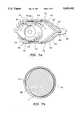
- FIG. 4is a perspective view of a laminar light emitting means mounted on an eyelid speculum
- FIG. 5is a plan view, partially cut away, of the apparatus of FIG. 4;
- FIG. 6is a plan view, partially cut away, of a second embodiment of a laminar light emitting means mounted on an eyelid speculum;
- FIG. 7is a plan view, partially cut away, of a third embodiment of a laminar light emitting means mounted on an eyelid speculum;
- FIG. 7ais a plan view of a variation of the embodiment shown in FIG. 7;
- FIG. 7bis a section view taken on line 7b--7b in FIG. 7a.
- FIG. 8is a left elevation view of the embodiment shown in FIG. 8;
- FIG. 9is a front elevation view of a fixation ring assembly having a laminar light emitting means
- FIG. 10is a side elevation view of the fixation ring assembly of FIG. 9;
- FIG. 11is a perspective view of a second embodiment of a fixation ring assembly having a laminar light emitting means
- FIG. 12is a section view taken on line 12--12 in FIG. 11;
- FIG. 13is a front elevation view of a third embodiment of a fixation ring assembly having a laminar light emitting means
- FIG. 14is a detail side elevation view of the ring portion of the assembly of FIG. 13;
- FIG. 15is a perspective view of a fourth embodiment of a ring assembly using a light pipe light emitter and a suction mounting ring;
- FIG. 16is a section view taken on line 16--16 in FIG. 15.
- FIG. 1is an axial section through an eye 10, schematically illustrating the light path of axial lighting 12 from a conventional microscope lighting system (not shown). As shown, a portion 14 of the light passes directly through cornea 15 to the back of the eye, causing discomfort to the patient. Another portion 16 of the incident light reflects from the front surface of the eye, causing glare. Only a small part 18 of the light is reflected from incisions and the like within the iris. Thus, a surgeon must use rather intense light to receive sufficient feedback light from the areas of surgical interest.
- FIG. 2shows the path of light 20 which enters eye 10 at an low angler nearly parallel with the plane of the iris and cornea 15.
- This lightingtermed “generally lamellar lighting", which is primarily scleral scatter, directs the light into the lamellae of cornea 15 where it follows the path shown until a disruption such as incision 22 is encountered to scatter light 23, making the incision particularly visible to the surgeon viewing the incision through a surgical microscope.
- a bright dotgenerally appears at the knife tip, making the precise location of the knife readily apparent.
- some light 24 entering as retro illumination at a higher anglemay pass through the cornea and be reflected at the eye interior.
- Lightreflects off the surface of the eye at an angle that prevents direct entrance into the axis of the operating microscope and thus prevents glare.
- Light 26 reflected from internal structures such as iris 21is attenuated and provides a back lit (retro illumination) of the cornea.
- Such illuminationsignificantly enhances visualization of fine corneal detail.
- Light scattered by any object, such as an embedded foreign body, or incision in the eye or any corneal discontinuities (not shown)will scatter light in the manner shown in FIG. 2 and become visible through the microscope. Because of the acute entrance angle, only a very small portion of the entering light will reach the back of the eye, avoiding patient discomfort.
- Offset lamellar lightingis illustrated in FIG. 3a, with the lighted directed parallel to the eye axis (90° to the eye plane). This provides both retro illumination and sclerotic scatter with the benefits described above. The offset nature of the narrowly focussed beam prevents direct or refracted light from entering the pupillary axis.
- lamellar lightingwhich is a combination of scleral scatter and retro illumination, avoids significant light impact on the back of the eye and associated patient discomfort and phototoxicity. Generally lamellar lighting also avoids glare which makes viewing a surgical field through a microscope difficult.
- Lightshould enter the eye at an angle of from about 0° to 90° to the plane of the iris 21, as done by the apparatus hereinafter described. In particular circumstances, a particular angle within that range may be preferred.
- the irisis the contractile circular diaphragm forming the colored portion of the eye.
- the plane of eye iris 21 for the purposes of this applicationis considered to be the plane in which the outer edge of the iris substantially lies.
- a housing 28 containing a light source 30is mounted on, or formed as part of, a conventional eyelid speculum 32.
- Speculum 32includes two arcuate members 34 mounted on arms 36 and shaped to engage and spread apart a patient's eyelids 34 to keep a central surgical field clear. Arms 36 are mounted on a handle 40.
- Each housing 28includes an elongated opening 42 oriented to direct light into the eye as shown in FIG. 2. Opening 42 may have any suitable dimensions. In general, a relatively thin slit is preferred, oriented at a predetermined angle to the eye plane within a range of from about 0° to 90°.
- the interior of housing 28is preferably highly reflective. Any suitable light source 30 may be used. While a light emitting diode as shown is preferred in this embodiment, any other light source, such as incandescent bulbs, fiber optics, lasers, light pipes, electroluminescent means etc. may be used if desired.
- FIG. 6shows an alternate arrangement in which an eyelid speculum 44 includes two hollow arms 46, each of which has a pair of "U” or “J” shaped hooks 48 sized to retract eyelids from the surgical field.
- Fiber optic bundles 50extend down handle 52 and along each arm 46, terminating in emitting ends 54 spaced along arms 46.
- the fiber optic bundlesmay extend within handle 52 as shown or may be supported along the handle exterior.
- Ends 54are preferably in a plane radially oriented toward the center of the pupil, parallel to the iris plane when the speculum is in place.
- the light from light emitting ends 54enters the eye at a predetermined angle or range of angles to the plane of the iris of from about 0° to 90°.
- Any suitable source of lightmay be used to introduce light into the receiving ends of fiber bundles 50 in handle 52 or beyond.
- Typical light sourcesinclude incandescent bulbs, light emitting diodes, light reflected from the normal microscope illumination system, laser, electro luminescent panels, etc.
- FIGS. 7 and 8A further embodiment of a speculum-mounted generally lamellar light source is shown in FIGS. 7 and 8.
- speculum 58includes arms 60, handle 62 and hook members 64 for restraining the eyelids.
- a light pipe 65formed from conventional light pipe materials includes rods 66 extending from handle portion 68 and generally trapezoidal light emitting ends 70. As is usual, the light pipe 65 is internally reflecting except for a line 74 along the surface facing cornea 72.
- the partial ring of light produced by light pipecan enter the eye at any predetermined angle between about 0° to 90° to the eye plane by selecting the distance between line 74 on opposite sides of the eye and the orientation of the line toward the eye.
- the facing surfacemay be planar or curved, generally conforming to the cornea edge, and may include focussing optics to accomplish a desired beam profile, as desired. Any suitable source of light may be used to introduce light into the light receiving end (not shown) of light pipe 65 in handle 68 or beyond.
- the entire speculumcould be fabricated from light pipe material having sufficient flexibility so that the arms can be compressed together and released to retract the eyelids.
- a line of electro luminescent materialcould be employed along line 74, with ends 70 being simple supports and power wires running along rods 66 in place of the light pipe materials. While in many cases the light pipes are preferred for higher possible illumination levels, the electro luminescent panels may provide sufficient light for certain forms of eye surgery.
- FIGS. 7a and 7bA further variation of the embodiment of FIGS. 7-8 is shown in FIGS. 7a and 7b.
- the speculumis mounted on arms 60 extending from handle portion 68, with ends 70 being hollow tubes on which hook members 64 are mounted. Ends 70 house and frictionally engage ends of a light pipe 65.
- An elongated slot 71is formed along a portion of each end 70, extending radially around a portion of the end 70.
- a focussing lens 73may be an integral part of the light pipe or may be secured to the light pipe end within slot 71 by adhesive bonding or the like. Typically, lens 73 will condense light emitted by light pipe 65 on the surface of the eye or at some other desired distance from the light pipe. By moving tab 75, the focussed beam's angle of incidence could be changed to any desired angle between 0° and 90°.
- lens 75may be omitted and the surface of light pipe 65 could be coated with an opaque material, leaving an uncoated, light transmitting line corresponding to the base of lens 75. That light emitting line could be moved transverse to the length of slot 71 by manually moving tab 75.
- slot 71could be replaced with a plurality of spaced, parallel slots, so that the light pipe could be rotated to align the light emitting line with any individual slot, so that light would be emitted at a precise selected angle.
- a tab 75is fastened to light pipe 65 adjacent to end 70 so that the light pipe can be rotated to move focussing lens 75 along slot 71 so that the light can be concentrated at an angle to the iris plane of from about 0° to 90°.
- any of the other illumination means described herein, such as LED's and the likecould be used in this embodiment in a manner similar to the other speculum embodiments.
- FIGS. 9 and 10An embodiment of the apparatus for illuminating the eye by generally lamellar lighting which uses a fixation ring is shown in FIGS. 9 and 10.
- a ring 76sized to fit around and near a cornea, is mounted on a handle 78.
- Fiber optic bundles (or single thicker optical fibers) 80extend along handle 78 and terminate in light emitting ends 82 positioned to introduce generally lamellar light into the eye, at the angles described above.
- the fiber opticsmay be supported either along the exterior of handle 78 or in a longitudinal opening in handle 78, as desired. While any suitable number of fiber optic bundles 80 may be used, two as shown are effective. If desired, the fiber optic bundles 80 may run alongside handle 78 as shown or may extend up through a hollow handle to a light source.
- a light source within the handlecould be optically reflected down a hollow channel within the handle and reflected to exit at the desired angle of illumination.
- a fixation ringmay be hingedly fixed to the handle or other support means to provide an adjustable angle of light emanating from the support means toward the cornea. Any of the light sources mentioned above may be used.
- the ends 82 of the fiber opticsmay be spaced apart and bent to form a partial ring of light projected toward the eye at any desired angle between 0° and 90°.
- FIGS. 11 and 12show a light pipe version of the fixation ring assembly shown in FIGS. 9 and 10, where handle 84 and ring 86 are formed from conventional light pipe material, such as coated acrylic or other suitable materials.
- Light from an appropriate sourceenters the distal end of handle 84 (not shown) as described above, and passes around ring 86.
- a bevel 88is shaped to emit light at the desired angle, preferably 0° to 90° to the iris plane as described above.
- ring 86acts both as a fixation ring around a cornea during surgery and the light source.
- FIGS. 13 and 14show a particularly preferred version of a fixation ring type instrument.
- a ring 90preferably a 270° segment of a circle, includes two guides 92 which form a 90° included angle.
- Two projecting stops 94are provided at the desired location along guides 92.
- a diamond surgical blade mounted in a holderis moved along guides 94 toward the center of the cornea.
- the ring 90may then be rotated and two additional radial incisions made. With ring 90 centered on the eye, the blade holder will be stopped at the precise desired location by stops 94, to prevent cutting into the visual axis of the eye.
- Ring 90is pivotally mounted on two arms 96 which are in turn mounted on handle 98.
- Two fiber optic bundles 100extend down through opening in handle 98 (or, if desired along the exterior of the handle) to light emitting ends 104.
- handle 104can be tilted and the ends 104 and angled and spaced to provide any desired angle to the iris plane, within the 0° to 90° range, to produce optimum illumination.
- any suitable light sourcemay be used, as detailed above. If desired, batteries and a light source such as an incandescent bulb, light emitting diode or the like may be enclosed within handle 98.
- the terminal end 100may be replaced with an optical means to create a generally linear beam of light directed at the desired angle.
- FIGS. 15 and 16An embodiment of a fixation ring including light emitting and position stabilizing means is shown in FIGS. 15 and 16.
- Ring 106is a light pipe ring generally similar to that shown in FIGS. 11 and 12, but with flat, parallel, upper and lower surfaces and a light emitting surface on the inner surface.
- a light pipe 107is optically connected to ring 106 and extends to a light source (not shown) of the sort detailed above.
- Handle 107may be formed from a flexible material which can be secured to any nearby support means, so that the ring assembly is pressed against the eye without any requirement that the handle be physically held by a person. Further, handle 107 may be adjustable or flexible so that the end of the handle can be fastened to other structures, such as an eyelid speculum, with a ball and socket or other movable mount.
- a coextensive channel ring 108is secured to ring 106 with the channel open side adapted to be placed on the surface of an eye.
- Ring 108is formed from a soft rubbery material, such as a silicone rubber. When pressed against the eye surface around a cornea, ring 108 will deform slightly and provide a "suction cup" effect.
- the inner leg of the ring channelis slightly shorter than the outer ring to generally conform to the eye curvature.
- Ring 106can be simply rested upon the eye or could be affixed in a hinged manner to another support means, such as an eyelid speculum.
- the inside surface of ring 106can be configured to provide any desired impingement angle to the eye plane in the 0° to 90° range.
Landscapes
- Health & Medical Sciences (AREA)
- Life Sciences & Earth Sciences (AREA)
- Surgery (AREA)
- Animal Behavior & Ethology (AREA)
- Public Health (AREA)
- Engineering & Computer Science (AREA)
- Biomedical Technology (AREA)
- Heart & Thoracic Surgery (AREA)
- Veterinary Medicine (AREA)
- General Health & Medical Sciences (AREA)
- Nuclear Medicine, Radiotherapy & Molecular Imaging (AREA)
- Ophthalmology & Optometry (AREA)
- Medical Informatics (AREA)
- Molecular Biology (AREA)
- Oral & Maxillofacial Surgery (AREA)
- Pathology (AREA)
- Vascular Medicine (AREA)
- Physics & Mathematics (AREA)
- Biophysics (AREA)
- Eye Examination Apparatus (AREA)
Abstract
Description
Claims (25)
Priority Applications (1)
| Application Number | Priority Date | Filing Date | Title |
|---|---|---|---|
| US08/748,056US5695492A (en) | 1995-04-11 | 1996-11-13 | Lamellar illumination apparatus for eye surgery |
Applications Claiming Priority (2)
| Application Number | Priority Date | Filing Date | Title |
|---|---|---|---|
| US08/420,129US5582608A (en) | 1995-04-11 | 1995-04-11 | Lamellar illumination apparatus for eye surgery |
| US08/748,056US5695492A (en) | 1995-04-11 | 1996-11-13 | Lamellar illumination apparatus for eye surgery |
Related Parent Applications (1)
| Application Number | Title | Priority Date | Filing Date |
|---|---|---|---|
| US08/420,129Continuation-In-PartUS5582608A (en) | 1995-04-11 | 1995-04-11 | Lamellar illumination apparatus for eye surgery |
Publications (1)
| Publication Number | Publication Date |
|---|---|
| US5695492Atrue US5695492A (en) | 1997-12-09 |
Family
ID=46251137
Family Applications (1)
| Application Number | Title | Priority Date | Filing Date |
|---|---|---|---|
| US08/748,056Expired - LifetimeUS5695492A (en) | 1995-04-11 | 1996-11-13 | Lamellar illumination apparatus for eye surgery |
Country Status (1)
| Country | Link |
|---|---|
| US (1) | US5695492A (en) |
Cited By (51)
| Publication number | Priority date | Publication date | Assignee | Title |
|---|---|---|---|---|
| WO1999062442A1 (en)* | 1998-05-29 | 1999-12-09 | Wavelight Laser Technologie Gmbh | Device for medical treatment with a light source |
| US6161931A (en)* | 1999-06-14 | 2000-12-19 | University Of New Mexico | Fiberoptic fundoscope coupler |
| USD439976S1 (en) | 1999-11-10 | 2001-04-03 | Becton, Dickinson And Company | Surgical swivel fixation ring device |
| US6213997B1 (en)* | 1993-08-23 | 2001-04-10 | Refractec, Inc. | Apparatus for modifications of visual acuity by thermal means |
| US6267752B1 (en)* | 1999-08-05 | 2001-07-31 | Medibell Medical Vision Technologies, Ltd. | Multi-functional eyelid speculum |
| US6299617B1 (en)* | 1998-03-30 | 2001-10-09 | John Stamler | Instrument for fixating the eye during cataract surgery |
| US20020002369A1 (en)* | 1993-08-23 | 2002-01-03 | Hood Larry L. | Method and apparatus for modifying visual acuity by moving a focal point of energy within a cornea |
| EP1113754A4 (en)* | 1998-06-25 | 2002-01-23 | Michael S Korenfeld | SMOKE EXTRACTOR FOR A SURGICAL LASER |
| US20030156252A1 (en)* | 2001-10-19 | 2003-08-21 | Morris Robert E. | Macula cover and method |
| US20030181903A1 (en)* | 1993-08-23 | 2003-09-25 | Hood Larry L. | Method and apparatus for modifications of visual acuity by thermal means |
| US6673069B1 (en) | 2000-03-30 | 2004-01-06 | Refractec, Inc. | Thermokeratoplasty system with a power supply that can determine a wet or dry cornea |
| US6723093B2 (en) | 2002-03-22 | 2004-04-20 | Refractec Inc. | Electrode assembly for a thermokeratoplasty system used to correct vision acuity |
| US20040267294A1 (en)* | 2003-06-27 | 2004-12-30 | Will Brian R. | Eye fixation apparatus |
| US7311401B2 (en) | 1998-11-24 | 2007-12-25 | Welch Allyn, Inc. | Eye viewing device comprising eyepiece and video capture optics |
| US7364297B2 (en) | 2003-10-28 | 2008-04-29 | Welch Allyn, Inc. | Digital documenting ophthalmoscope |
| WO2007136888A3 (en)* | 2006-05-19 | 2008-12-31 | Envision Eyes L L C | External eye speculum |
| USD601698S1 (en) | 2007-07-11 | 2009-10-06 | Envision Eyes, Llc | Eye speculum |
| EP2345362A1 (en)* | 2010-01-18 | 2011-07-20 | Dieter Mann GmbH | Fundus camera |
| US8142352B2 (en) | 2006-04-03 | 2012-03-27 | Welch Allyn, Inc. | Vaginal speculum assembly having portable illuminator |
| US8157728B2 (en) | 2005-04-01 | 2012-04-17 | Welch Allyn, Inc. | Vaginal speculum |
| US8388523B2 (en) | 2005-04-01 | 2013-03-05 | Welch Allyn, Inc. | Medical diagnostic instrument having portable illuminator |
| WO2013174140A1 (en)* | 2012-05-23 | 2013-11-28 | 中山市人民医院 | Device and method for propping eyelids open |
| WO2015164881A1 (en)* | 2014-04-25 | 2015-10-29 | Mindskid Labs, Llc | Illuminating speculum |
| US9289199B1 (en)* | 2014-01-09 | 2016-03-22 | Neotech Products, Inc. | Retinal examination apparatus |
| US9307897B2 (en) | 2010-09-28 | 2016-04-12 | Obp Corporation | Disposable speculum having lateral stabilizing mechanism |
| US20160367397A1 (en)* | 2014-08-12 | 2016-12-22 | Katalyst Surgical, Llc | Multi-function capsulorhexis guide |
| US9532706B2 (en) | 2014-08-07 | 2017-01-03 | Welch Allyn, Inc. | Vaginal speculum with illuminator |
| US9867602B2 (en) | 2015-02-05 | 2018-01-16 | Obp Medical Corporation | Illuminated surgical retractor |
| US9913577B2 (en) | 2010-09-28 | 2018-03-13 | Obp Medical Corporation | Speculum |
| US9956053B2 (en)* | 2016-03-04 | 2018-05-01 | Novartis Ag | Cannula with an integrated illumination feature |
| US20180280109A1 (en)* | 2017-03-31 | 2018-10-04 | Mindskid Labs, Llc | Apparatus for illuminating an eye related application |
| US10244931B2 (en) | 2015-07-13 | 2019-04-02 | Novartis Ag | Illuminated ophthalmic infusion line and associated devices, systems, and methods |
| US10278572B1 (en) | 2017-10-19 | 2019-05-07 | Obp Medical Corporation | Speculum |
| US10420538B2 (en) | 2015-02-05 | 2019-09-24 | Obp Medical Corporation | Illuminated surgical retractor |
| US10512519B2 (en) | 2018-02-20 | 2019-12-24 | Obp Medical Corporation | Illuminated medical devices |
| US10687793B2 (en) | 2017-07-18 | 2020-06-23 | Obp Medical Corporation | Minimally invasive no touch (MINT) procedure for harvesting the great saphenous vein (GSV) and venous hydrodissector and retractor for use during the MINT procedure |
| US10722621B2 (en) | 2016-07-11 | 2020-07-28 | Obp Medical Corporation | Illuminated suction device |
| US10799229B2 (en) | 2018-02-20 | 2020-10-13 | Obp Medical Corporation | Illuminated medical devices |
| USD904607S1 (en) | 2019-05-07 | 2020-12-08 | Obp Medical Corporation | Nasal retractor |
| US10881387B2 (en) | 2015-06-03 | 2021-01-05 | Obp Medical Corporation | Retractor |
| USD911521S1 (en) | 2019-02-19 | 2021-02-23 | Obp Medical Corporation | Handle for medical devices including surgical retractors |
| US10939899B2 (en) | 2015-06-03 | 2021-03-09 | Obp Medical Corporation | End cap assembly for retractor and other medical devices |
| US10952712B2 (en) | 2015-06-03 | 2021-03-23 | Obp Medical Corporation | Retractor |
| US10959609B1 (en) | 2020-01-31 | 2021-03-30 | Obp Medical Corporation | Illuminated suction device |
| US10966702B1 (en) | 2020-02-25 | 2021-04-06 | Obp Medical Corporation | Illuminated dual-blade retractor |
| US11006093B1 (en) | 2020-01-22 | 2021-05-11 | Photonic Medical Inc. | Open view, multi-modal, calibrated digital loupe with depth sensing |
| US11166708B2 (en)* | 2019-12-13 | 2021-11-09 | Alcon Inc. | Trans-scleral illumination system for vitreoretinal surgery |
| US11173008B2 (en) | 2015-11-01 | 2021-11-16 | Alcon Inc. | Illuminated ophthalmic cannula |
| US11298118B1 (en)* | 2018-11-19 | 2022-04-12 | Edward Y. Koo | Systems and methods for combined periocular direct-illumination and trans-conjunctival and trans-scleral retro-illumination during ophthalmic surgery |
| WO2023233111A1 (en)* | 2022-06-03 | 2023-12-07 | Universite Jean Monnet Saint Etienne | Device for examining the anterior part of the eye by retro-illumination of said anterior part of the eye |
| US12318080B2 (en) | 2023-07-21 | 2025-06-03 | Coopersurgical, Inc. | Illuminated surgical retractor capable of hand-held operation and of being mounted to a fixed frame |
Citations (10)
| Publication number | Priority date | Publication date | Assignee | Title |
|---|---|---|---|---|
| US4905711A (en)* | 1988-03-08 | 1990-03-06 | Taunton Technologies, Inc. | Eye restraining device |
| US5092863A (en)* | 1990-04-09 | 1992-03-03 | St. Louis University | Ophthalmological surgery apparatus and methods |
| US5102409A (en)* | 1988-04-22 | 1992-04-07 | Balgorod Barry M | Method and apparatus for modification of corneal refractive properties |
| US5108412A (en)* | 1988-11-11 | 1992-04-28 | Jorg H. Krumeich | Suction ring for surgical operations on the human eye |
| US5133708A (en)* | 1988-01-14 | 1992-07-28 | Smith Robert F | Method for controlled corneal ablation |
| US5141506A (en)* | 1985-10-22 | 1992-08-25 | York Kenneth K | Systems and methods for creating substrate surfaces by photoablation |
| US5425727A (en)* | 1988-04-01 | 1995-06-20 | Koziol; Jeffrey E. | Beam delivery system and method for corneal surgery |
| US5437658A (en)* | 1992-10-07 | 1995-08-01 | Summit Technology, Incorporated | Method and system for laser thermokeratoplasty of the cornea |
| US5490849A (en)* | 1990-07-13 | 1996-02-13 | Smith; Robert F. | Uniform-radiation caustic surface for photoablation |
| US5582608A (en)* | 1995-04-11 | 1996-12-10 | Brown; Alan W. | Lamellar illumination apparatus for eye surgery |
- 1996
- 1996-11-13USUS08/748,056patent/US5695492A/ennot_activeExpired - Lifetime
Patent Citations (10)
| Publication number | Priority date | Publication date | Assignee | Title |
|---|---|---|---|---|
| US5141506A (en)* | 1985-10-22 | 1992-08-25 | York Kenneth K | Systems and methods for creating substrate surfaces by photoablation |
| US5133708A (en)* | 1988-01-14 | 1992-07-28 | Smith Robert F | Method for controlled corneal ablation |
| US4905711A (en)* | 1988-03-08 | 1990-03-06 | Taunton Technologies, Inc. | Eye restraining device |
| US5425727A (en)* | 1988-04-01 | 1995-06-20 | Koziol; Jeffrey E. | Beam delivery system and method for corneal surgery |
| US5102409A (en)* | 1988-04-22 | 1992-04-07 | Balgorod Barry M | Method and apparatus for modification of corneal refractive properties |
| US5108412A (en)* | 1988-11-11 | 1992-04-28 | Jorg H. Krumeich | Suction ring for surgical operations on the human eye |
| US5092863A (en)* | 1990-04-09 | 1992-03-03 | St. Louis University | Ophthalmological surgery apparatus and methods |
| US5490849A (en)* | 1990-07-13 | 1996-02-13 | Smith; Robert F. | Uniform-radiation caustic surface for photoablation |
| US5437658A (en)* | 1992-10-07 | 1995-08-01 | Summit Technology, Incorporated | Method and system for laser thermokeratoplasty of the cornea |
| US5582608A (en)* | 1995-04-11 | 1996-12-10 | Brown; Alan W. | Lamellar illumination apparatus for eye surgery |
Cited By (92)
| Publication number | Priority date | Publication date | Assignee | Title |
|---|---|---|---|---|
| US6213997B1 (en)* | 1993-08-23 | 2001-04-10 | Refractec, Inc. | Apparatus for modifications of visual acuity by thermal means |
| US20020002369A1 (en)* | 1993-08-23 | 2002-01-03 | Hood Larry L. | Method and apparatus for modifying visual acuity by moving a focal point of energy within a cornea |
| US20030181903A1 (en)* | 1993-08-23 | 2003-09-25 | Hood Larry L. | Method and apparatus for modifications of visual acuity by thermal means |
| US6299617B1 (en)* | 1998-03-30 | 2001-10-09 | John Stamler | Instrument for fixating the eye during cataract surgery |
| WO1999062442A1 (en)* | 1998-05-29 | 1999-12-09 | Wavelight Laser Technologie Gmbh | Device for medical treatment with a light source |
| EP1113754A4 (en)* | 1998-06-25 | 2002-01-23 | Michael S Korenfeld | SMOKE EXTRACTOR FOR A SURGICAL LASER |
| US7311401B2 (en) | 1998-11-24 | 2007-12-25 | Welch Allyn, Inc. | Eye viewing device comprising eyepiece and video capture optics |
| US7784940B2 (en) | 1998-11-24 | 2010-08-31 | Welch Allyn, Inc. | Eye viewing device comprising video capture optics |
| US6161931A (en)* | 1999-06-14 | 2000-12-19 | University Of New Mexico | Fiberoptic fundoscope coupler |
| US6267752B1 (en)* | 1999-08-05 | 2001-07-31 | Medibell Medical Vision Technologies, Ltd. | Multi-functional eyelid speculum |
| USD439976S1 (en) | 1999-11-10 | 2001-04-03 | Becton, Dickinson And Company | Surgical swivel fixation ring device |
| US6673069B1 (en) | 2000-03-30 | 2004-01-06 | Refractec, Inc. | Thermokeratoplasty system with a power supply that can determine a wet or dry cornea |
| US20030156252A1 (en)* | 2001-10-19 | 2003-08-21 | Morris Robert E. | Macula cover and method |
| US6886565B2 (en) | 2001-10-19 | 2005-05-03 | Innovative Retinal Products Llc | Macula cover and method |
| WO2003039333A3 (en)* | 2001-10-19 | 2004-02-12 | Innovative Retinal Products Ll | Macula cover and method |
| US6723093B2 (en) | 2002-03-22 | 2004-04-20 | Refractec Inc. | Electrode assembly for a thermokeratoplasty system used to correct vision acuity |
| US20040267294A1 (en)* | 2003-06-27 | 2004-12-30 | Will Brian R. | Eye fixation apparatus |
| US7364297B2 (en) | 2003-10-28 | 2008-04-29 | Welch Allyn, Inc. | Digital documenting ophthalmoscope |
| US9883792B2 (en) | 2005-04-01 | 2018-02-06 | Welch Allyn, Inc. | Vaginal speculum apparatus |
| US9332898B2 (en) | 2005-04-01 | 2016-05-10 | Welch Allyn, Inc. | Vaginal speculum apparatus |
| US8157728B2 (en) | 2005-04-01 | 2012-04-17 | Welch Allyn, Inc. | Vaginal speculum |
| US9949633B2 (en) | 2005-04-01 | 2018-04-24 | Welch Allyn, Inc. | Vaginal speculum apparatus |
| US8388523B2 (en) | 2005-04-01 | 2013-03-05 | Welch Allyn, Inc. | Medical diagnostic instrument having portable illuminator |
| US8435175B2 (en) | 2005-04-01 | 2013-05-07 | Welch Allyn, Inc. | Vaginal speculum apparatus |
| US11291359B2 (en)* | 2005-04-01 | 2022-04-05 | Welch Allyn, Inc. | Vaginal speculum apparatus |
| US8821395B2 (en) | 2005-04-01 | 2014-09-02 | Welch Allyn, Inc. | Vaginal speculum apparatus |
| US12262878B2 (en) | 2005-04-01 | 2025-04-01 | Welch Allyn, Inc. | Vaginal speculum apparatus |
| US8142352B2 (en) | 2006-04-03 | 2012-03-27 | Welch Allyn, Inc. | Vaginal speculum assembly having portable illuminator |
| WO2007136888A3 (en)* | 2006-05-19 | 2008-12-31 | Envision Eyes L L C | External eye speculum |
| USD601698S1 (en) | 2007-07-11 | 2009-10-06 | Envision Eyes, Llc | Eye speculum |
| US20110176109A1 (en)* | 2010-01-18 | 2011-07-21 | Dieter Mann Gmbh | Fundus Camera |
| US8353595B2 (en) | 2010-01-18 | 2013-01-15 | Dieter Mann Gmbh | Fundus camera |
| EP2345362A1 (en)* | 2010-01-18 | 2011-07-20 | Dieter Mann GmbH | Fundus camera |
| US9307897B2 (en) | 2010-09-28 | 2016-04-12 | Obp Corporation | Disposable speculum having lateral stabilizing mechanism |
| US11744454B2 (en) | 2010-09-28 | 2023-09-05 | Obp Medical Corporation | Speculum |
| US10368733B2 (en) | 2010-09-28 | 2019-08-06 | Obp Medical Corporation | Speculum |
| US9913577B2 (en) | 2010-09-28 | 2018-03-13 | Obp Medical Corporation | Speculum |
| US12419510B2 (en) | 2010-09-28 | 2025-09-23 | Coopersurgical, Inc. | Speculum |
| WO2013174140A1 (en)* | 2012-05-23 | 2013-11-28 | 中山市人民医院 | Device and method for propping eyelids open |
| US9289199B1 (en)* | 2014-01-09 | 2016-03-22 | Neotech Products, Inc. | Retinal examination apparatus |
| WO2015164881A1 (en)* | 2014-04-25 | 2015-10-29 | Mindskid Labs, Llc | Illuminating speculum |
| US9532706B2 (en) | 2014-08-07 | 2017-01-03 | Welch Allyn, Inc. | Vaginal speculum with illuminator |
| US10945594B2 (en) | 2014-08-07 | 2021-03-16 | Welch Allyn, Inc. | Vaginal speculum with illuminator |
| US20160367397A1 (en)* | 2014-08-12 | 2016-12-22 | Katalyst Surgical, Llc | Multi-function capsulorhexis guide |
| US11439379B2 (en) | 2015-02-05 | 2022-09-13 | Obp Surgical Corporation | Illuminated surgical retractor |
| US11197662B2 (en) | 2015-02-05 | 2021-12-14 | Obp Surgical Corporation | Illuminated surgical retractor |
| US10420538B2 (en) | 2015-02-05 | 2019-09-24 | Obp Medical Corporation | Illuminated surgical retractor |
| US10420540B2 (en) | 2015-02-05 | 2019-09-24 | Obp Medical Corporation | Illuminated surgical retractor |
| US12329370B2 (en) | 2015-02-05 | 2025-06-17 | Coopersurgical, Inc. | Illuminated surgical retractor |
| US9867602B2 (en) | 2015-02-05 | 2018-01-16 | Obp Medical Corporation | Illuminated surgical retractor |
| US12089829B2 (en) | 2015-02-05 | 2024-09-17 | Obp Surgical Corporation | Illuminated surgical retractor |
| US10952712B2 (en) | 2015-06-03 | 2021-03-23 | Obp Medical Corporation | Retractor |
| US12201287B2 (en) | 2015-06-03 | 2025-01-21 | Coopersurgical, Inc. | Retractor |
| US10881387B2 (en) | 2015-06-03 | 2021-01-05 | Obp Medical Corporation | Retractor |
| US10966699B2 (en) | 2015-06-03 | 2021-04-06 | Obp Medical Corporation | Retractor |
| US11622756B2 (en) | 2015-06-03 | 2023-04-11 | Obp Surgical Corporation | End cap assembly for retractor and other medical devices |
| US10939899B2 (en) | 2015-06-03 | 2021-03-09 | Obp Medical Corporation | End cap assembly for retractor and other medical devices |
| US10244931B2 (en) | 2015-07-13 | 2019-04-02 | Novartis Ag | Illuminated ophthalmic infusion line and associated devices, systems, and methods |
| US11173008B2 (en) | 2015-11-01 | 2021-11-16 | Alcon Inc. | Illuminated ophthalmic cannula |
| US9956053B2 (en)* | 2016-03-04 | 2018-05-01 | Novartis Ag | Cannula with an integrated illumination feature |
| US11717374B2 (en) | 2016-07-11 | 2023-08-08 | Obp Surgical Corporation | Illuminated suction device |
| US10722621B2 (en) | 2016-07-11 | 2020-07-28 | Obp Medical Corporation | Illuminated suction device |
| US10660629B2 (en)* | 2017-03-31 | 2020-05-26 | Mindskid Labs, Llc | Apparatus for illuminating an eye |
| US20180280109A1 (en)* | 2017-03-31 | 2018-10-04 | Mindskid Labs, Llc | Apparatus for illuminating an eye related application |
| US10687793B2 (en) | 2017-07-18 | 2020-06-23 | Obp Medical Corporation | Minimally invasive no touch (MINT) procedure for harvesting the great saphenous vein (GSV) and venous hydrodissector and retractor for use during the MINT procedure |
| US11540817B2 (en) | 2017-07-18 | 2023-01-03 | Obp Surgical Corporation | Minimally invasive no touch (MINT) procedure for harvesting the great saphenous vein (GSV) and venous hydrodissector and retractor for use during the mint procedure |
| US10441155B2 (en) | 2017-10-19 | 2019-10-15 | Obp Medical Corporation | Medical devices with battery removal |
| US10278572B1 (en) | 2017-10-19 | 2019-05-07 | Obp Medical Corporation | Speculum |
| US12383129B2 (en) | 2017-10-19 | 2025-08-12 | Coopersurgical, Inc. | Medical devices with battery removal |
| US11253145B2 (en) | 2017-10-19 | 2022-02-22 | Obp Medical Corporation | Speculum |
| US10912455B2 (en) | 2017-10-19 | 2021-02-09 | Obp Medical Corporation | Medical devices with battery removal |
| US10512519B2 (en) | 2018-02-20 | 2019-12-24 | Obp Medical Corporation | Illuminated medical devices |
| US10799229B2 (en) | 2018-02-20 | 2020-10-13 | Obp Medical Corporation | Illuminated medical devices |
| US11744568B2 (en) | 2018-02-20 | 2023-09-05 | Obp Surgical Corporation | Illuminated medical devices |
| US11298118B1 (en)* | 2018-11-19 | 2022-04-12 | Edward Y. Koo | Systems and methods for combined periocular direct-illumination and trans-conjunctival and trans-scleral retro-illumination during ophthalmic surgery |
| US11759194B1 (en) | 2018-11-19 | 2023-09-19 | Edward Y. Koo | Systems and methods for combined periocular direct-illumination and trans-conjunctival and trans-scleral retro-illumination during ophthalmic surgery |
| USD911521S1 (en) | 2019-02-19 | 2021-02-23 | Obp Medical Corporation | Handle for medical devices including surgical retractors |
| USD904607S1 (en) | 2019-05-07 | 2020-12-08 | Obp Medical Corporation | Nasal retractor |
| US11166708B2 (en)* | 2019-12-13 | 2021-11-09 | Alcon Inc. | Trans-scleral illumination system for vitreoretinal surgery |
| US11611735B2 (en) | 2020-01-22 | 2023-03-21 | Photonic Medical Inc. | Open view, multi-modal, calibrated digital loupe with depth sensing |
| US11412202B2 (en) | 2020-01-22 | 2022-08-09 | Photonic Medical Inc. | Open view, multi-modal, calibrated digital loupe with depth sensing |
| US11166006B2 (en) | 2020-01-22 | 2021-11-02 | Photonic Medical Inc. | Open view, multi-modal, calibrated digital loupe with depth sensing |
| US11006093B1 (en) | 2020-01-22 | 2021-05-11 | Photonic Medical Inc. | Open view, multi-modal, calibrated digital loupe with depth sensing |
| US12075019B2 (en) | 2020-01-22 | 2024-08-27 | Photonic Medical Inc. | Open view, multi-modal, calibrated digital loupe with depth sensing |
| US11617822B2 (en) | 2020-01-31 | 2023-04-04 | Obp Surgical Corporation | Illuminated suction device |
| US10959609B1 (en) | 2020-01-31 | 2021-03-30 | Obp Medical Corporation | Illuminated suction device |
| US12246124B2 (en) | 2020-01-31 | 2025-03-11 | Coopersurgical, Inc. | Illuminated suction device |
| US11622758B2 (en) | 2020-02-25 | 2023-04-11 | Obp Surgical Corporation | Illuminated dual-blade retractor |
| US10966702B1 (en) | 2020-02-25 | 2021-04-06 | Obp Medical Corporation | Illuminated dual-blade retractor |
| FR3136150A1 (en)* | 2022-06-03 | 2023-12-08 | Universite Jean Monnet Saint Etienne | Device for examining the anterior part of the eye by retro-illumination of said anterior part of the eye |
| WO2023233111A1 (en)* | 2022-06-03 | 2023-12-07 | Universite Jean Monnet Saint Etienne | Device for examining the anterior part of the eye by retro-illumination of said anterior part of the eye |
| US12318080B2 (en) | 2023-07-21 | 2025-06-03 | Coopersurgical, Inc. | Illuminated surgical retractor capable of hand-held operation and of being mounted to a fixed frame |
Similar Documents
| Publication | Publication Date | Title |
|---|---|---|
| US5695492A (en) | Lamellar illumination apparatus for eye surgery | |
| US5582608A (en) | Lamellar illumination apparatus for eye surgery | |
| WO2015164881A1 (en) | Illuminating speculum | |
| US7063436B2 (en) | Light source for ophthalmic use | |
| ES2549781T3 (en) | Illuminated microsurgical instrument including optical fiber with bevelled end face | |
| JP5453311B2 (en) | Illuminated lighting for surgical instruments | |
| US5312393A (en) | Ring lighting system for microsurgery | |
| US5013319A (en) | Apparatus and method for cornea marking | |
| US4772115A (en) | Illuminated ring keratometer device | |
| JP4643218B2 (en) | Surgical wide-angle illuminator | |
| US6080143A (en) | Intraocular slit illuminator and method therefor | |
| KR20080068730A (en) | Surgical Wide Angle Illuminator | |
| US8333482B2 (en) | Ophthalmic endoillumination with light collector for white phosphor | |
| US20090030406A1 (en) | Variable intensity endoilluminator | |
| US4429421A (en) | Method of implanting an intraocular lens | |
| US10660629B2 (en) | Apparatus for illuminating an eye | |
| US5513286A (en) | White light dimmer for fiber optic illumination sources | |
| EP1164918B1 (en) | A device for self examination of the transparent optical system of the eye and a method for use thereof | |
| WO2023068359A1 (en) | Intraocular illumination device and attachment for intraocular illumination | |
| RU2575051C2 (en) | Illuminated microsurgical instrument comprising oblique optical fibre | |
| JPWO2023068359A5 (en) |
Legal Events
| Date | Code | Title | Description |
|---|---|---|---|
| FPAY | Fee payment | Year of fee payment:4 | |
| FPAY | Fee payment | Year of fee payment:8 | |
| REMI | Maintenance fee reminder mailed | ||
| FEPP | Fee payment procedure | Free format text:PETITION RELATED TO MAINTENANCE FEES DISMISSED (ORIGINAL EVENT CODE: PMFS); ENTITY STATUS OF PATENT OWNER: SMALL ENTITY | |
| FEPP | Fee payment procedure | Free format text:PETITION RELATED TO MAINTENANCE FEES FILED (ORIGINAL EVENT CODE: PMFP); ENTITY STATUS OF PATENT OWNER: SMALL ENTITY | |
| FEPP | Fee payment procedure | Free format text:PETITION RELATED TO MAINTENANCE FEES FILED (ORIGINAL EVENT CODE: PMFP); ENTITY STATUS OF PATENT OWNER: SMALL ENTITY | |
| LAPS | Lapse for failure to pay maintenance fees | ||
| REIN | Reinstatement after maintenance fee payment confirmed | ||
| LAPS | Lapse for failure to pay maintenance fees | Free format text:PATENT EXPIRED FOR FAILURE TO PAY MAINTENANCE FEES (ORIGINAL EVENT CODE: EXP.); ENTITY STATUS OF PATENT OWNER: SMALL ENTITY | |
| FP | Lapsed due to failure to pay maintenance fee | Effective date:20091209 | |
| FEPP | Fee payment procedure | Free format text:PETITION RELATED TO MAINTENANCE FEES GRANTED (ORIGINAL EVENT CODE: PMFG); ENTITY STATUS OF PATENT OWNER: SMALL ENTITY Free format text:PETITION RELATED TO MAINTENANCE FEES FILED (ORIGINAL EVENT CODE: PMFP); ENTITY STATUS OF PATENT OWNER: SMALL ENTITY | |
| FEPP | Fee payment procedure | Free format text:PETITION RELATED TO MAINTENANCE FEES DISMISSED (ORIGINAL EVENT CODE: PMFS); ENTITY STATUS OF PATENT OWNER: SMALL ENTITY | |
| PRDP | Patent reinstated due to the acceptance of a late maintenance fee | Effective date:20110211 | |
| FPAY | Fee payment | Year of fee payment:12 | |
| STCF | Information on status: patent grant | Free format text:PATENTED CASE | |
| SULP | Surcharge for late payment |