US5695468A - Balloon catheter with improved pressure source - Google Patents
Balloon catheter with improved pressure sourceDownload PDFInfo
- Publication number
- US5695468A US5695468AUS08/586,514US58651496AUS5695468AUS 5695468 AUS5695468 AUS 5695468AUS 58651496 AUS58651496 AUS 58651496AUS 5695468 AUS5695468 AUS 5695468A
- Authority
- US
- United States
- Prior art keywords
- balloon
- balloon catheter
- tubular member
- catheter
- lumen
- Prior art date
- Legal status (The legal status is an assumption and is not a legal conclusion. Google has not performed a legal analysis and makes no representation as to the accuracy of the status listed.)
- Expired - Lifetime
Links
Images


Classifications
- A—HUMAN NECESSITIES
- A61—MEDICAL OR VETERINARY SCIENCE; HYGIENE
- A61M—DEVICES FOR INTRODUCING MEDIA INTO, OR ONTO, THE BODY; DEVICES FOR TRANSDUCING BODY MEDIA OR FOR TAKING MEDIA FROM THE BODY; DEVICES FOR PRODUCING OR ENDING SLEEP OR STUPOR
- A61M25/00—Catheters; Hollow probes
- A61M25/10—Balloon catheters
- A61M25/1018—Balloon inflating or inflation-control devices
- A61M25/10184—Means for controlling or monitoring inflation or deflation
- A61M25/10185—Valves
- A61M25/10186—One-way valves
- A—HUMAN NECESSITIES
- A61—MEDICAL OR VETERINARY SCIENCE; HYGIENE
- A61M—DEVICES FOR INTRODUCING MEDIA INTO, OR ONTO, THE BODY; DEVICES FOR TRANSDUCING BODY MEDIA OR FOR TAKING MEDIA FROM THE BODY; DEVICES FOR PRODUCING OR ENDING SLEEP OR STUPOR
- A61M25/00—Catheters; Hollow probes
- A61M25/10—Balloon catheters
- A61M25/1018—Balloon inflating or inflation-control devices
- A61M25/10184—Means for controlling or monitoring inflation or deflation
- A61M25/10187—Indicators for the level of inflation or deflation
- A—HUMAN NECESSITIES
- A61—MEDICAL OR VETERINARY SCIENCE; HYGIENE
- A61M—DEVICES FOR INTRODUCING MEDIA INTO, OR ONTO, THE BODY; DEVICES FOR TRANSDUCING BODY MEDIA OR FOR TAKING MEDIA FROM THE BODY; DEVICES FOR PRODUCING OR ENDING SLEEP OR STUPOR
- A61M25/00—Catheters; Hollow probes
- A61M25/10—Balloon catheters
- A61M25/1025—Connections between catheter tubes and inflation tubes
- A—HUMAN NECESSITIES
- A61—MEDICAL OR VETERINARY SCIENCE; HYGIENE
- A61M—DEVICES FOR INTRODUCING MEDIA INTO, OR ONTO, THE BODY; DEVICES FOR TRANSDUCING BODY MEDIA OR FOR TAKING MEDIA FROM THE BODY; DEVICES FOR PRODUCING OR ENDING SLEEP OR STUPOR
- A61M25/00—Catheters; Hollow probes
- A61M25/0043—Catheters; Hollow probes characterised by structural features
- A61M2025/0063—Catheters; Hollow probes characterised by structural features having means, e.g. stylets, mandrils, rods or wires to reinforce or adjust temporarily the stiffness, column strength or pushability of catheters which are already inserted into the human body
- A—HUMAN NECESSITIES
- A61—MEDICAL OR VETERINARY SCIENCE; HYGIENE
- A61M—DEVICES FOR INTRODUCING MEDIA INTO, OR ONTO, THE BODY; DEVICES FOR TRANSDUCING BODY MEDIA OR FOR TAKING MEDIA FROM THE BODY; DEVICES FOR PRODUCING OR ENDING SLEEP OR STUPOR
- A61M25/00—Catheters; Hollow probes
- A61M2025/0098—Catheters; Hollow probes having a strain relief at the proximal end, e.g. sleeve
- A—HUMAN NECESSITIES
- A61—MEDICAL OR VETERINARY SCIENCE; HYGIENE
- A61M—DEVICES FOR INTRODUCING MEDIA INTO, OR ONTO, THE BODY; DEVICES FOR TRANSDUCING BODY MEDIA OR FOR TAKING MEDIA FROM THE BODY; DEVICES FOR PRODUCING OR ENDING SLEEP OR STUPOR
- A61M25/00—Catheters; Hollow probes
- A61M25/10—Balloon catheters
- A61M25/1018—Balloon inflating or inflation-control devices
- A61M2025/102—Balloon inflating or inflation-control devices driven by a solenoid-activated pump
- A—HUMAN NECESSITIES
- A61—MEDICAL OR VETERINARY SCIENCE; HYGIENE
- A61M—DEVICES FOR INTRODUCING MEDIA INTO, OR ONTO, THE BODY; DEVICES FOR TRANSDUCING BODY MEDIA OR FOR TAKING MEDIA FROM THE BODY; DEVICES FOR PRODUCING OR ENDING SLEEP OR STUPOR
- A61M25/00—Catheters; Hollow probes
- A61M25/10—Balloon catheters
- A61M2025/1043—Balloon catheters with special features or adapted for special applications
- A61M2025/1056—Balloon catheters with special features or adapted for special applications having guide wire lumens outside the main shaft, i.e. the guide wire lumen is within or on the surface of the balloon
- A—HUMAN NECESSITIES
- A61—MEDICAL OR VETERINARY SCIENCE; HYGIENE
- A61M—DEVICES FOR INTRODUCING MEDIA INTO, OR ONTO, THE BODY; DEVICES FOR TRANSDUCING BODY MEDIA OR FOR TAKING MEDIA FROM THE BODY; DEVICES FOR PRODUCING OR ENDING SLEEP OR STUPOR
- A61M25/00—Catheters; Hollow probes
- A61M25/10—Balloon catheters
- A61M2025/1043—Balloon catheters with special features or adapted for special applications
- A61M2025/1077—Balloon catheters with special features or adapted for special applications having a system for expelling the air out of the balloon before inflation and use
Definitions
- the present inventiongenerally relates to balloon catheters. More specifically, the present invention relates to balloon dilation catheters used for the treatment of vascular disease. Those skilled in the art will recognize the benefits of applying the present invention to similar fields not discussed herein.
- Coronary artery diseaseis an adverse condition of the heart in which the blood flow to the heart muscle is partially or totally restricted by occlusive material in the coronary arteries which narrows the blood flow lumen.
- the occlusive materialsdeprive portions of the heart muscle of essential oxygenated blood.
- CADmay be treated by a surgical technique referred to as coronary artery bypass graft (CABG) surgery.
- CABGcoronary artery bypass graft
- This surgical procedureinvolves supplementing blood flow to the heart muscle by grafting a non-native conduit such as a saphenous vein graft (SVG) to the heart.
- a first end of the SVGis connected to the ascending aorta (proximal to the occlusive material) and the other end is connected to the artery distal of the occlusive material.
- PTCAPercutaneous translumenal coronary angioplasty
- the PTCA procedureinvolves the use of an angioplasty balloon catheter, several types of which are well known in the art.
- the balloon catheteris inserted into the body via the femoral artery and navigated to the coronary arteries assisted by a guide catheter and (usually) a guide wire.
- the balloonis positioned across the restriction in the artery and subsequently inflated.
- the inflated balloonwidens the restriction and restores blood flow to portions of the heart muscle previously deprived of oxygenated blood.
- a PTCA balloon catheteris typically about 135 to 150 cm long and has a manifold at its proximal end and a balloon at its distal end. The manifold facilitates connection to an inflation device which is used to inflate and deflate the balloon.
- a conventional PTCA balloon catheteralso includes an inflation lumen extending through its entire length to facilitate the delivery of inflation fluid to and from the balloon. Depending on the type of catheter used, an inflation lumen may be circular in cross section or it may be annular in cross section. Some catheters have an inflation lumen which is circular at the proximal end of the shaft and annular at the distal end of the shaft.
- the inflation lumen extending through the shaftis proportionately small.
- the long length of a typical inflation lumen in combination with its relatively small sizecreate a significant resistance to the flow of inflation fluid. Consequently, the time required to inflate and deflate the balloon is also long.
- the drag on the inflation fluidis particularly noticeable during balloon deflation when the maximum possible pressure gradient is 14.7 psi.
- the deflation timeis clinically significant because an excessively long deflation time will compromise the treating physician's ability to relieve aschemia and/or reestablish blood flow across the occlusion being dilated.
- the compliance of the inflation fluid, the inflation device and the entire structure defining the fluid pathadd to the delay in balloon deflation and inflation. The compliance of the fluid system reduces the immediate responsiveness of the balloon to actuation of the inflation device.
- An inflation deviceis usually in the form of a modified 20 cc syringe and typically includes a threaded plunger with a handle and lock mechanism, and a pressure gauge. Due to its size and weight, a typical inflation device is extremely bulky as compared to a PTCA catheter.
- Prior art balloon dilation catheters and inflation deviceshave certain disadvantages which are desirable to overcome. For example, it is desirable to reduce the inflation/deflation time of a balloon catheter and increase the immediate responsiveness of the balloon. This would allow for a more rapid balloon deflation and thus relieve aschemia and other adverse reactions to prolonged balloon inflation. Reducing inflation/deflation time would also allow for more effective use of the pulsating balloon technique. Eliminating a significant amount of the fluid system compliance would allow the treating physician to better "feel" the response of the vascular restriction to the inflation of the balloon. These desirable aspects would improve the treating physician's capabilities to treat CAD.
- Eliminating the need for an inflation devicewould, for example, reduce the number accessory devices needed in a procedure, reduce the number prepping procedures required, reduce the necessary storage space, and reduce the amount of medical waste generated in a procedure. All of these benefits would ultimately save a significant amount of time and expense on behalf of the treating physician, the medical support staff, the hospital and the patient.
- the present inventionovercomes the disadvantages of the prior art and provides the desirable features outlined above by eliminating the need for an inflation device and an inflation lumen.
- the present inventioninter alia, reduces the drag on inflation fluid and reduces the compliance of the inflation system.
- the reduction in drag and compliancecorrelates to an increase in balloon responsiveness which may be clinically significant for the reasons discussed previously. Eliminating the need for an inflation device and an inflation lumen also correlates to savings of time and money.
- the present inventionmay be described as a balloon catheter which includes a sealed chamber in fluid communication with a distally mounted balloon and a fluid displacement member disposed at least partially within the sealed chamber to displace fluid into or out of the balloon.
- one embodiment of the present inventionis a balloon catheter which includes a long tubular member having a balloon connected to it's distal end.
- a fluid displacement rodis at least partially and slidably disposed in the tubular member such that the balloon may be expanded when the rod is slid into the tubular member.
- a sealis connected to the proximal end of the tubular member and disposed about the displacement rod to create a liquid seal between the inside of the tubular member and the displacement rod.
- the sealmay, for example, be an o-ring type seal or a gap tolerance type seal.
- a pressure gaugemay be connected to the proximal end of the elongate tubular member to measure pressure inside the balloon.
- the balloon cathetermay be a fixed wire, an over-the-wire or a single-operator-exchange type balloon catheter.
- a one-way-valvemay be connected to the distal end of the tubular member to permit fluid to flow from the guide wire lumen to the interior of the balloon and to prevent fluid from flowing from the interior of the balloon to the guide wire lumen.
- the valvemay be connected to a portion of the tubular member traversing the interior of the balloon and the valve may include an elastomer tube disposed about a hole in the tubular member under the balloon.
- the one-way-valveprovides a means to prep the catheter (i.e., replace all the air in the catheter with liquid) prior to use in-vivo.
- One end of the guide wire lumene.g., the proximal end
- the other end of the guide wire lumene.g., the distal end
- the pressurized liquid sourcemay be connected to the distal end of the guide wire lumen with a tubular member disposed about the balloon and the tubular member may retain the balloon in a contracted state (sometimes referred to as a balloon protector).
- the present inventionmay also be described as a method of using a balloon catheter including the following steps: (1) providing a balloon catheter (wherein the balloon catheter includes a long tubular member having a balloon connected to it's distal end, a fluid displacement rod at least partially and slidably disposed in the tubular member, and a seal connected to the proximal end of the tubular member and disposed about the displacement rod); (2) inserting the balloon catheter into a vascular system of a patient; (3) positioning the balloon catheter adjacent a treatment site in the vascular system; (4) displacing the rod to at least partially expand the balloon; (5) displacing the rod to at least partially contract the balloon; and (6) withdrawing the balloon catheter from the vascular system.
- a balloon catheterwhich includes a long shaft having a lumen disposed therein which extends from a point distal of the proximal end of the shaft to the distal end of the shaft.
- a balloonis connected to the distal end of the shaft and a one-way-valve is also connected to the distal end of the shaft.
- the one-way-valveprovides a means to prep the catheter (i.e., replace all the air in the catheter with liquid) prior to use in-vivo.
- the one-way-valvepermits fluid to flow from the lumen to the interior of the balloon while preventing fluid to flow from the interior of the balloon to the lumen.
- the valvemay be connected to a portion of the tubular member traversing the interior of the balloon and the valve may include an elastomer tube disposed about a hole in the tubular member under the balloon.
- One end of the lumene.g., the proximal end
- the other end of the lumene.g., the distal end
- the pressurized liquid sourcemay be connected to the distal end of the lumen with a tubular member disposed about the balloon and the tubular member may retain the balloon in a contracted state.
- the present inventionmay also be described as a method of prepping a balloon catheter including the following steps: (1) providing a balloon catheter (where the balloon catheter includes a long shaft with a lumen disposed therein, a balloon connected to the distal end of the shaft and a one-way-valve also connected to the distal end of the shaft); (2) providing a pressurized fluid source containing fluid therein (such as a fluid filled syringe); (3) connecting the pressurized fluid source to the distal end of the balloon catheter; (4) plugging the proximal end of the balloon catheter; and (5) forcing fluid from the pressurized fluid source into the catheter such that the fluid passes into the tubular member, through the one-way-valve and into the interior of the balloon.
- a pressurized fluid source containing fluid thereinsuch as a fluid filled syringe
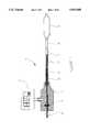
- FIG. 1is a partially-sectioned side view of a generic embodiment of the present invention.
- FIGS. 2, 3a, 3b, 4a and 4bshow specific examples of catheter embodiments utilizing some of the generic features shown in FIG. 1.
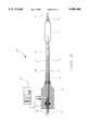
- FIG. 2shows a partially-sectioned side view of a fixed wire catheter embodiment.
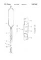
- FIGS. 3a and 3bshow, respectively, partially-sectioned side views of a side-by-side lumen over-the-wire catheter embodiment and a coaxial over-the-wire catheter embodiment.
- FIGS. 4a and 4bshow partially-sectioned side views of two single-operator-exchange catheter embodiments.
- FIG. 5ashows a partially-sectioned side view of a one-way valve incorporated into the distal section of either an over-the-wire or a single-operator-exchange catheter.
- FIG. 5bshows a detailed view of the one-way valve and
- FIG. 5cshows a tubular fitting over the distal end of the balloon catheter to facilitate prepping the balloon catheter via the one-way valve.
- FIG. 6ashows a partially-sectioned side view of the distal section of a generic catheter incorporating a one-way valve proximal of the balloon.
- FIG. 6bshows a detailed view of the one-way valve.
- FIG. 6cshows a first embodiment of a system facilitating prepping a balloon catheter, utilizing a one-way valve as shown in FIGS. 6a and 6b.
- FIG. 6dshows a detailed view of the passive seal utilized in the prepping system shown in FIG. 6c.
- FIG. 6eshows a second embodiment of a system facilitating prepping a balloon catheter utilizing a one-way valve as shown in FIGS. 6a and 6b.
- FIG. 6fshows a detailed view of the active seals used in the prepping system shown in FIG. 6e.
- FIGS. 7a and 7bshow plan views of two mechanisms which facilitate manipulation of the fluid displacement rod.
- Generic catheter 10includes an elongate shaft 11 with a balloon 12 connected to its distal end and a manifold 13 connected to its proximal end.
- a fluid displacement rod 14is disposed inside the elongate shaft 11 and is longitudinally movable therein.
- Proximal seal 15creates a fluid seal between the inside of the elongate shaft 11 and the displacement rod 14 such that longitudinal actuation of displacement rod 14 causes a bolus of liquid 18 to move into or out of the inflatable balloon 12.
- the rod 14displaces liquid bolus 18 into the internal volume of the balloon 12.
- bolus of liquidor “liquid bolus” as used in this application is defined as a closed volume of liquid that is relatively large as compared to the static column of fluid 17 between the rod 14 and the inside diameter of the shaft 11.
- the generic catheter 10may take the form of any balloon catheter and may be used in a variety of medical procedures.
- the generic catheter 10may take the form of a fixed wire catheter (FIG. 2), an over-the-wire catheter (FIGS. 3a and 3b) or a single-operator-exchange catheter (FIGS. 4a and 4b) and may be used in coronary, peripheral, cerebral and urethral applications.
- the generic catheter 10may incorporate other clinically-significant features such as perfusion or drug delivery capabilities.
- the exemplary embodimentsare directed to a catheter system which is particularly suitable for PTCA procedures.
- the generic catheter 10may be used for other medical applications not fully discussed herein.
- the balloon 12may be constructed in a variety of ways.
- the material of balloon 10may be selected from polymers including, but not limited to, polyolefin copolymer, polyester, polyethylene terephthalate, polyethylene, polyether block amide, polyamide, polyimide, nylon, latex and urethane.
- the balloon 12may be made by blow-molding a polymer extrusion into the desired shape.
- a number of ancillary processesmay be used to affect the material properties of the balloon 12.
- the polymer extrusionmay be exposed to gamma radiation which alters the polymer infrastructure to provide uniform expansion during blow-molding and additional burst strength when in use.
- the molded balloon 12may be exposed to a low temperature plasma field which alters the surface properties of the balloon 12 to provide enhanced adhesion characteristics.
- a low temperature plasma fieldwhich alters the surface properties of the balloon 12 to provide enhanced adhesion characteristics.
- the shaft 11may be made of several different constructions, materials and dimensions, depending on the performance characteristics desired.
- the shaft 11may be made of, for example, an extruded polymer tube, a stainless steel hypotube or a composite material such as stainless steel braid encased in polyimide.
- the shaft 11may incorporate changes in diameter or combine different constructions.
- the shaft 11may have a composite proximal section combined with a polymer distal section.
- connections between the various polymer componentsmay be made utilizing suitable medical grade adhesives or thermal bonds well known in the art.
- Connections between metallic componentsmay be made, for example, by utilizing a solder, braze or weld joint.
- Manifold 13may be formed of various polymers such as injection molded polycarbonate. Seal 15 may be made of a conventional sealing material such as silicone rubber and is secured in a recess formed in the manifold 13.
- the pressure gaugemay be secured to the manifold 13 utilizing a threaded connection, an adhesive connection, a thermal weld, or any other suitable means.
- a strain relief 19such as a polymer or metallic tube may be secured to the manifold 13 and/or proximal end of the shaft 11 to reduce the tendency of the shaft 11 to kink immediately adjacent the distal end of the manifold 13.
- Fluid displacement rod 14may be in the form of a solid rod, a tube or a combination thereof.
- fluid displacement rod 14may be a metallic or polymer rod having a circular cross section.
- Fluid displacement rod 14must have a sufficient length to at least partially extend inside the shaft 11 and at least partially extend proximal of the manifold 13.
- the fluid displacement rodmust have sufficient length to extend proximal of the manifold when the rod 14 is fully displaced in the distal direction.
- the portion of the rod 14 extending proximal of the manifold 13provides a handle for the treating physician to grasp and control longitudinal actuation of the rod 14.
- fluid displacement rod 14extends as far as possible into the shaft 11 to minimize the distance that liquid bolus 18 has to travel and thus increase the responsiveness of the balloon 12. Fluid displacement rod 14 must also have sufficient volume to displace liquid bolus 18 to cause expansion of the balloon 12 when the rod 14 is longitudinally displaced in the distal direction. In addition, fluid displacement rod 14 must have sufficient volume to displace liquid bolus 18 to cause contraction of the balloon 12 when the rod 14 is longitudinally displaced in the proximal direction.
- pressure gauge 16is fluidly linked to liquid bolus 18 by way of static fluid column 17.
- liquid bolus 18exerts a force on the static column of fluid 17 which transfers the force to the pressure gauge 16.
- the cross-sectional area of static fluid column 17is preferably minimized to reduce the outside profile of the elongate shaft 11. Minimizing the cross-sectional area of static fluid column 17 does not impede the ability of pressure gauge 16 to measure the pressure of liquid bolus 18 and thus the internal pressure of balloon 12 since the static column of fluid 17 merely transfers force from the liquid bolus 18 to the pressure gauge 16 and accordingly, does not flow.
- Pressure gauge 16is preferably a low compliance pressure gauge utilizing a piezoelectric crystal transducer.
- generic catheter 10is used in a manner somewhat similar to conventional balloon catheters.
- the steps associated with inserting the device in-vivo and positioning the balloon across the treatment siteare essentially the same as with conventional balloon catheters.
- the steps for prepping the catheter 10 and inflating the catheter 10are different.
- the prepping methods and the balloon expansion methods of the present inventionare independent. That is to say that the prepping method may be used without the expansion method and vice-versa, without compromising the advantages associated with each method.
- the generic catheter 10may, for example, be prepped by filling the catheter with liquid prior to final packaging (discussed below) or the catheter may be prepped by utilizing the prep methods discussed below with reference FIGS. 5 and 6. These prep methods are exemplary only and those skilled in the art will recognize that other prep methods may also be utilized. After the catheter 10 is prepped, the catheter may be inserted in-vivo and positioned across the treatment site in essentially the same manner as a conventional balloon catheter.
- the balloon 12may be expanded by longitudinally actuating the displacement rod 14.
- Longitudinal actuation of the displacement rod 14is accomplished by pushing the rod distally while holding the manifold 13 and the shaft 11 relatively fixed. Since the proximal seal 15 creates a fluid tight seal between the inside of the elongate shaft 11 and the displacement rod 14, longitudinal actuation of displacement rod 14 in the distal direction causes the bolus of liquid 18 to move into the inflatable balloon 12. Further distal advancement of the rod 14 causes the pressure inside the balloon 12 to increase. Accordingly, the balloon 12 is expanded to the desired size and/or pressure as measured by angiography and/or the pressure gauge 16.
- the static column of fluid 17links the pressure gauge 16 to the liquid bolus 18 and allows measurement of the internal pressure of the balloon 12.
- the treating physicianmay contract the balloon by reversing the actuation steps.
- liquid bolus 18exits the balloon and causes the balloon 12 to contract.
- the catheter 10is removed in substantially the same manner as conventional balloon catheters.
- the catheter 10may be prepped prior to final packaging.
- the interior of the catheter 10would be filled with a liquid after final assembly but before final packaging such that the catheter 10 would be pre-prepped upon removal from the packaging.
- the packagingwould also be filled with the same or similar liquid in order to prevent liquid egress from the interior of the catheter.
- the inside of the packagingmay be filled with a dissimilar fluid that is not mixable with the fluid inside the catheter. For example, if the catheter is filled with a water base solution, an oil base solution may be placed in the packaging to retard liquid egress from inside the catheter.
- the packagingmay be filled with a liquid saturated gas at a pressure at equilibrium with the interior of the catheter. Under these conditions, there would be no pressure or saturation gradient causing fluid egress from inside the catheter.
- generic catheter 10may take the form of a variety of balloon catheters including a fixed wire type balloon catheter.
- FIG. 2shows a partially-sectioned side view of a fixed wire catheter embodiment 20.
- Fixed wire catheter 20is similar to generic catheter 10 except for the following differences.
- Fixed wire catheter 20includes an elongate shaft 21 with a balloon 12 sealingly connected to its distal end and a manifold 13 sealingly connected to its proximal end.
- a strain relief 19such as a polymer or metallic tube may be secured to the manifold 13 and/or proximal end of the shaft 21 to reduce the tendency of the shaft 21 to kink immediately adjacent the distal end of the manifold 13.
- a core wire 22is connected to the distal end of the elongate shaft 21 and extends through the proximal waist of the balloon, traverses the interior of the balloon and terminates with a radiopaque spring tip 23 extending beyond the distal end of the balloon 12. The distal end of the balloon 12 is sealingly connected to the spring tip 23.
- a radiopaque marker band 24is secured to the core wire 22 to facilitate radiographic placement of the catheter 20.
- Elongate shaft 21is preferably made of a medical grade metal such as stainless steel or a super elastic alloy such as a Nickel-Titanium alloy having a length of about 44.0 inches, an inside diameter of about 0.014 inches and an outside diameter of about 0.021 inches.
- Core wire 22may also be made of a medical grade metal such as stainless steel or a super elastic alloy such as a Nickel-Titanium alloy and may be soldered, brazed or welded to the distal end of the elongate shaft 21.
- Core wire 22may have a length of about 14.0 inches and a diameter tapering from about 0.012 inches proximally to about 0.002 inches distally.
- the spring tip 23may be coiled about the distal end of the core wire 22 and is preferably made of a radiopaque metal alloy such as an Iridium-Tungsten alloy. Spring tip 23 may be soldered, brazed or welded to the core wire 22 at both ends of the spring coil. Radiopaque marker band 24 is preferably made of Gold, Platinum or Iridium-Tungsten and may be adhesively secured or soldered to core wire 22 at approximately the axial center of the balloon 12.
- generic catheter 10may take the form of an over-the-wire type balloon catheter.
- FIGS. 3a and 3bshow, respectively, partially-sectioned side views of a side-by-side lumen over-the-wire catheter embodiment 30a and a coaxial over-the-wire catheter embodiment 30b.
- a more detailed description of a known side-by-side lumen over-the-wire cathetercan be found in U.S. Pat. No. 5,382,234 to Cornelius et al. and a more detailed description of a known coaxial over-the-wire catheter can be found in U.S. Pat. No. 5,100,381 to Burns.
- Over-the-wire catheters 30a and 30bare similar to generic catheter 10 except for the following differences.
- Side-by-side lumen over-the-wire catheter 30aincludes a dual lumen shaft 31a with an inflatable balloon 12 connected to its distal end and a manifold 33a connected to its proximal end.
- Guide wire 32passes through manifold 33a, into the dual lumen shaft 31a, through the shaft extension 37a and exits distally of the balloon 12.
- the distal end of the balloon 12is sealingly connected to the distal end of the shaft extension 37a and the proximal end of the balloon is sealingly connected to the distal end of the dual lumen shaft 31a.
- a strain relief 19such as a polymer or metallic tube may be secured to the manifold 33a and/or the proximal end of the dual lumen shaft 31a to reduce the tendency of the shaft 31a to kink immediately adjacent the distal end of the manifold 33a.
- a radiopaque marker band 24may be secured to the shaft extension 37a to facilitate radiographic placement of the catheter 30a.
- Dual lumen shaft 31amay be made of a dual lumen extruded polymer or two separate tubes secured together side-by-side. Dual lumen shaft 31a may have a length of about 52.0 inches and an outer diameter of approximately 0.040 inches. Shaft extension 37a may be a partial continuation of the dual lumen shaft 31a or a separate tube secured to the distal end of the dual lumen shaft 31a. Radiopaque marker band 24 is preferably made of Gold, Platinum or Iridium-Tungsten and may be adhesively secured to the shaft extension 37a at approximately the axial center of the balloon 12.
- Coaxial over-the-wire catheter 30bincludes an elongate shaft 31b with a balloon 12 sealingly connected to its distal end and a manifold 33b sealingly connected to its proximal end.
- a strain relief 19such as a polymer or metallic tube may be secured to the manifold 33b and/or the proximal end of the shaft 31b to reduce the tendency of the shaft 31b to kink immediately adjacent the distal end of the manifold 33b.
- a fluid displacement tube 34bis slidably disposed in elongate shaft 31b.
- Proximal seal 15provides a liquid tight seal between the interior of the elongate shaft 31b and the exterior of the displacement tube 34b.
- a guide wire 32extends through the interior of the fluid displacement tube 34b, through the distal end of the elongate shaft 31b and exits distally of the balloon 12.
- Proximal guide wire seal 36bprovides a fluid tight seal between the guide wire 32 and the interior of the fluid displacement tube 34b.
- Distal guide wire seal 37bprovides a fluid tight seal between the interior of the balloon 12 and the guide wire 32.
- Shaft 31bmay be formed of a polymer extrusion or composite tube having a length of about 52.0 inches and an outer diameter of about 0.040 inches.
- Displacement tube 34bmay be formed of a reinforced polymer tube having a length of about 50.0 inches, an inner diameter of about 0.018 inches and an outer diameter of about 0.025 inches.
- suitable guide wire seals 36b/37bare disclosed in commonly-assigned co-pending patent application Ser. No. 08/443,496 entitled "Single Operator Exchange Perfusion Catheter Having a Distal Catheter Shaft Section" which is fully incorporated herein by reference.
- generic catheter 10may take the form of a single-operator-exchange type balloon catheter.
- FIGS. 4a and 4bshow partially-sectioned side views of two single-operator-exchange catheter embodiments.
- catheter 40ais a generic single-operator-exchange catheter embodiment while catheter 40b is a relatively specific single-operator-exchange catheter embodiment.
- a more detailed description of a known single-operator-exchange balloon cathetercan be found in U.S. Pat. No. 5,156,594 to Keith et al.
- Single-operator-exchange catheters 40a and 40bare similar to generic catheter 10 except for the following differences.
- Single-operator-exchange catheter 40aincludes an elongate shaft 41a with a balloon 12 sealingly connected to its distal end and a manifold 13 sealingly connected to its proximal end.
- a strain relief 19such as a polymer or metallic tube may be secured to the manifold 13 and/or the proximal end of the shaft 41a to reduce the tendency of the shaft 41a to kink immediately adjacent the distal end of the manifold 13.
- a guide wire tube 42ahas a distal end sealingly connected to the distal end of the balloon and a proximal end defining a proximal guide wire port 48a in communication with the exterior of the catheter 40a and sealingly connected to the elongate shaft 41a.
- Proximal guide wire port 48ais located at a point substantially distal of the proximal end of the catheter 40a and proximal of the distal end of the catheter 40a.
- a guide wire(not shown) may traverse the interior of the guide wire tube 42a such that the guide wire enters the proximal guide wire port 48a and exits distally of the balloon 12.
- a radiopaque marker band 24may be secured to the guide wire tube 42a to facilitate radiographic placement of the catheter 40a.
- Single-operator-exchange catheter 40bincludes a proximal shaft section 41b with a manifold 13 connected to its proximal end and a distal shaft section 43b connected to its distal end.
- a strain relief 19such as a polymer or metallic tube may be secured to the manifold 13 and/or the proximal end of the shaft 41b to reduce the tendency of the shaft to kink immediately adjacent the distal end of the manifold 13.
- An additional strain relief 44bmay traverse the connection between the proximal shaft 41b and the distal shaft 43b. Strain relief 44b reduces the tendency of the distal shaft 43b to kink immediately adjacent the distal end of the proximal shaft 41b.
- a core wire 47bhas a proximal end rigidly connected to the distal end of the proximal shaft 41b and/or the proximal end of the distal shaft 43b.
- Core wire 47btransfers longitudinal force from the distal end of the proximal shaft 41b, provides for decreasing diametric stiffness along the length of the distal shaft 43b and acts as a strain relief reducing the propensity of the distal shaft 43b to kink immediately adjacent the crimp section 45b.
- Guide wire tube 42bis sealingly connected at its distal end to the distal end of the balloon 12.
- the proximal end of the guide wire tube 42bdefines a proximal guide wire port 48b in communication with the exterior of the catheter 40b and sealingly connected to the distal shaft 43b.
- Proximal guide wire portis located at a point substantially distal of the proximal end of the catheter 40a and preferably about 2.75 inches proximal of the distal end of the catheter 40a.
- a guide wire(not shown) may traverse the interior of the guide wire tube 42b such that the guide wire enters the proximal guide wire port 48b and exits distally of the balloon 12.
- a radiopaque marker band 24may be secured to the guide wire tube 42b to facilitate radiographic placement of the catheter 40b.
- a one-way valve 51may be connected to the guide wire tube 42b to facilitate prepping the catheter 40b. The incorporation of one-way-valve 51 to facilitate prepping is preferred but not necessary as other suitable prep methods known to those skilled in the art may also be employed. One-way valve 51 and the prepping method are discussed in detail with reference to FIGS. 5a-5c.
- Proximal shaft 41bis preferably made of a polyimide-encased stainless steel braid having an inside diameter of approximately 0.0394 inches, an outside diameter of about 0.0466 inches and a length of approximately 44.0 inches.
- the stainless steel braid embedded in the polyimidepreferably has a pick-per-inch ratio ranging from about 50 to about 70.
- the stainless steel braidis preferably made of woven stainless steel ribbon having a width of approximately 0.005 inches and a height of approximately 0.0007 inches.
- Manifold 13may be adhesively secured to the proximal end of the elongate proximal shaft 41b by means of a suitable medical grade adhesive.
- Manifold 13is preferably made of injection-molded polycarbonate having an approximately 0.123 inch diameter recess provided for the proximal seal 15 which is preferably made of silicone having an inside diameter of about 0.042 inches and an outside diameter of about 0.142 inches.
- Pressure gauge 16preferably incorporates a piezoelectric crystal pressure transducer and a digital readout.
- Liquid displacement rod 14is preferably made of a stainless steel wire surrounded by a KynarTM tube.
- the stainless steel wirepreferably has a diameter of about 0.019 inches and a length of about 50.0 inches.
- the tube surrounding the wirepreferably has an outside diameter of about 0.038 inches and an inside diameter of about 0.020 inches.
- displacement rod 14When fully actuated in the distal direction, displacement rod 14 preferably may extend to the distal end of the proximal shaft section 41b to minimize the distance liquid bolus 18 has to travel and thus increase the responsiveness of the balloon.
- Distal shaft section 43bis preferably made of polyethylene having an outside diameter of about 0.0364 inches tapering to about 0.0335 inches, an inside diameter of about 0.0308 inches tapering to about 0.0277 inches and a length of about 8.0 inches.
- the proximal end of the distal shaft section 43bmay be adhesively secured to the distal end of the proximal shaft segment 41b.
- Strain relief 44bis preferably made of a stainless steel coil with an outside diameter of about 0.028 inches and a pitch of about 0.068 inches.
- the stainless steel coilis preferably formed by a coiled ribbon having a width of about 0.019 inches and a height of about 0.003 inches.
- the core wire 47bis preferably made of stainless steel having a proximal diameter of about 0.012 inches tapering to a distal diameter of about 0.003 inches.
- the proximal end of the core wire 47bis preferably brazed to the strain relief 44b which in turn is adhesively secured to the inside of the distal shaft segment 43b.
- Guide wire tube 42bis preferably made of polyethylene having an outside diameter of about 0.0215 inches, an inside diameter of about 0.0163 inches and a length of about 2.75 inches.
- the distal end of the guide wire tube 42bis adhesively secured to the distal end of the balloon 12 by a suitable medical grade adhesive.
- the proximal end of the guide wire tube 42bis preferably thermally bonded to the distal shaft section 43b in a crimped portion 45b of the distal shaft 43b.
- Balloon 12is preferably made of a blow-molded polyether-block-amide such as PEBAXTM 7233.
- the proximal end of the balloon 12may be adhesively secured to the distal end of the distal shaft segment 43b utilizing a suitable medical grade adhesive.
- the working portion of the balloon 12may range in length anywhere from 10 mm to 50 mm and may range in diameter anywhere from 1.0 mm to 10.0 mm.
- FIGS. 5a-5cshow a partially-sectioned side view of a one-way valve 51 incorporated into the distal section of a balloon catheter such as an over-the-wire or a single-operator-exchange type balloon catheter.
- One-way-valve 51may be incorporated into virtually any balloon catheter having a guide wire tube (or similar structure) traversing the interior of the balloon, including some of the balloon catheters discussed previously.
- One-way valve 51may be incorporated into guide wire tube 52 which traverses the interior of the balloon 53a.
- One-way valve 51includes an elastic tube 55 disposed about one or more holes 54 in the wall of guide wire tube 52.
- Elastic tube 55is preferably made of an elastomer such as TechothaneTM 1085A having a length of about 1.2 inches, an inside diameter of about 0.0165 inches and an outside diameter of about 0.023 inches.
- the elastic tube 55is preferably centered about two holes 54 formed through one side of the guide wire tube 52 wherein the holes 54 preferably have a diameter of about 0.009 inches.
- a tubular fitting 56such as a balloon protector is disposed over folded balloon 53b.
- a connector 57such as a luer fitting allows the tubular fitting to be connected to a pressurized fluid source such as a fluid-filled syringe (not shown).
- Tubular fitting 56fits snugly about folded balloon 53b such that fluid introduced into the tubular fitting 56 enters into the interior of the guide wire tube 52.
- elastic tube 55deflects in an outward direction permitting fluid to flow through holes 54 and into the interior of the catheter and the balloon 53.
- Elastic tube 55preferably requires a threshold actuation pressure of greater than one atmosphere of pressure to deflect and permit fluid to flow through holes 54. Having a threshold pressure above one atmosphere allows the balloon 53 to be contracted in a conventional manner (i.e., by pulling a vacuum at the proximal end of the catheter) without drawing any unwanted fluids through the one-way valve 51.
- one-way valve 51permits fluid to flow from the interior of the guide wire tube into the interior of the balloon 53 but does not permit flow from the interior of the balloon 53 to the interior of the guide wire tube 52.
- one-way valve 51may be located proximal of the balloon if the tubular fitting 56 maintains the balloon 53b in such a contracted state that an insignificant amount of air is trapped inside the balloon 53.
- a vacuum sourcesuch as a vacuum bottle may be connected to the proximal end of the catheter to facilitate filling the catheter shaft and the balloon 53 with liquid. To maximize effectiveness, the vacuum source should be applied prior to introducing pressurized fluid from the syringe.
- FIG. 6ashows a partially-sectioned side view of the distal section of a balloon catheter incorporating a one-way valve 61 proximal of the balloon.
- One-way-valve 61may be incorporated into virtually any balloon catheter in addition to those discussed above.
- One-way valve 61operates based on the same principles as one-way valve 51 discussed with reference to FIGS. 5a-5c.
- One-way valve 61is incorporated into a shaft 62 proximal of the balloon 69 and includes one or more holes 64 through the wall of the shaft 62.
- An elastic tube 65is disposed within the shaft 62 across the holes 64.
- one-way valve 61only permits flow from the exterior of the shaft 62 to the interior of the shaft at pressure gradients above one atmosphere.
- FIGS. 6c and 6dshow a first embodiment of a system facilitating prepping of a balloon catheter utilizing the one-way valve 61 as shown in FIGS. 6a and 6b.
- the catheter to be preppedincludes an elongate shaft 62 having a manifold 68 connected to its proximal end and a balloon 69 connected to its distal end.
- the catheteris disposed inside a carrier tube 67 which is conventional for balloon catheter packaging.
- the distal end of the carrier tube 67includes a connector 72 to facilitate connection to a pressurized fluid source such as a liquid-filled syringe 63.
- a passive seal 71such as an O-ring seal is connected to the inside of the carrier tube 67 at a point proximal of the one-way valve 61. Accordingly, when pressurized fluid is introduced by way of the syringe 63, fluid passes through the valve holes 64 and into the interior of the catheter shaft 62.
- a vacuum source 66such as a vacuum bottle may be connected to the manifold 68 to facilitate filling the catheter shaft 62 and the balloon 69 with liquid. To maximize effectiveness, vacuum source 66 applies a vacuum to the interior of the catheter shaft 62 prior to introducing pressurized fluid from the syringe 63.
- catheter shaft 62includes a manifold 68 connected to its proximal end and a balloon 69 connected to its distal end.
- a vacuum source 66may be connected to the manifold 68 to facilitate prepping as discussed previously.
- a syringe 63is connected to the carrier tube 67 utilizing connector tubes 84. Connector tubes 84 are in turn connected to active seals 81 and 82 located inside the carrier tube 67.
- active seals 81 and 82When pressurized fluid is introduced by the syringe 63 through the connector tubes 84, active seals 81 and 82 fluidly seal on either side of the one-way valve 61.
- active seals 81 and 82comprise oppositely-facing balloons which, upon inflation, seal about the catheter shaft 62 and the interior of the carrier tube 67.
- a small hole 83is placed in one of the active seals 81 or 82 such that fluid under pressure from syringe 63 seeps into the chamber defined between active seals 81 and 82.
- the fluid which seeps from hole 83is under sufficient pressure to deflect the elastic tube 65 and cause fluid to flow into the holes 64 and into the interior of the shaft 62, thus displacing air inside the catheter shaft 62 with liquid from the pressurized fluid source 63.
- displacement mechanism 71aincludes an engagement member 72a which engages the fluid displacement rod 14 when moved in the distal direction and accordingly causes fluid displacement rod 14 to also move in the distal direction.
- engagement member 72adisengages the fluid displacement rod 14 and slides thereon.
- Manifold 13(which is connected to the proximal end of the shaft 11) may include a thumb ring 73a and engagement member 72a may includes grooves 74a for receiving fingers such that the engagement member 72a may be grasped with middle and first fingers and the manifold may be grasped with the thumb.
- a metal tube 75amay be secured over the proximal portion of the rod 14 to add integrity to the displacement mechanism and avoid damage to the rod 14.
- Displacement mechanism 71bwhich facilitates advancement of fluid displacement rod 14.
- Displacement mechanism 71bincludes an engagement member 72b which incorporates a push button lock mechanism 73b.
- Push button lock mechanism 73bis normally locked onto the fluid displacement rod 14 such that depression of the push button on the lock mechanism 73b causes disengagement of the fluid displacement rod 14.
- a proximal portion 74b of the fluid displacement rod 14is threaded and is engaged by threads (not shown) inside manifold 13. Accordingly, the fluid displacement rod 14 is manually displaced in the distal direction with the push button on the lock mechanism 73b fully depressed (i.e., disengaged).
Landscapes
- Health & Medical Sciences (AREA)
- Life Sciences & Earth Sciences (AREA)
- Heart & Thoracic Surgery (AREA)
- Engineering & Computer Science (AREA)
- Biophysics (AREA)
- Pulmonology (AREA)
- Child & Adolescent Psychology (AREA)
- Anesthesiology (AREA)
- Biomedical Technology (AREA)
- Hematology (AREA)
- Animal Behavior & Ethology (AREA)
- General Health & Medical Sciences (AREA)
- Public Health (AREA)
- Veterinary Medicine (AREA)
- Media Introduction/Drainage Providing Device (AREA)
Abstract
Description
Claims (29)
Priority Applications (2)
| Application Number | Priority Date | Filing Date | Title |
|---|---|---|---|
| US08/586,514US5695468A (en) | 1994-09-16 | 1996-01-16 | Balloon catheter with improved pressure source |
| US08/812,390US5785685A (en) | 1994-09-16 | 1997-03-05 | Balloon catheter with improved pressure source |
Applications Claiming Priority (2)
| Application Number | Priority Date | Filing Date | Title |
|---|---|---|---|
| US08/308,025US5545133A (en) | 1994-09-16 | 1994-09-16 | Balloon catheter with improved pressure source |
| US08/586,514US5695468A (en) | 1994-09-16 | 1996-01-16 | Balloon catheter with improved pressure source |
Related Parent Applications (1)
| Application Number | Title | Priority Date | Filing Date |
|---|---|---|---|
| US08/308,025Continuation-In-PartUS5545133A (en) | 1994-09-16 | 1994-09-16 | Balloon catheter with improved pressure source |
Related Child Applications (1)
| Application Number | Title | Priority Date | Filing Date |
|---|---|---|---|
| US08/812,390Continuation-In-PartUS5785685A (en) | 1994-09-16 | 1997-03-05 | Balloon catheter with improved pressure source |
Publications (1)
| Publication Number | Publication Date |
|---|---|
| US5695468Atrue US5695468A (en) | 1997-12-09 |
Family
ID=26976060
Family Applications (1)
| Application Number | Title | Priority Date | Filing Date |
|---|---|---|---|
| US08/586,514Expired - LifetimeUS5695468A (en) | 1994-09-16 | 1996-01-16 | Balloon catheter with improved pressure source |
Country Status (1)
| Country | Link |
|---|---|
| US (1) | US5695468A (en) |
Cited By (96)
| Publication number | Priority date | Publication date | Assignee | Title |
|---|---|---|---|---|
| US5785685A (en)* | 1994-09-16 | 1998-07-28 | Scimed Life Systems, Inc. | Balloon catheter with improved pressure source |
| US5807330A (en)* | 1996-12-16 | 1998-09-15 | University Of Southern California | Angioplasty catheter |
| US5895373A (en)* | 1996-10-11 | 1999-04-20 | Abbott Laboratories | Feeding tube retaining member filling tool |
| US5947927A (en)* | 1998-03-23 | 1999-09-07 | Scimed Life Systems, Inc. | Convertible catheter having a single proximal lumen |
| US6042578A (en)* | 1996-05-13 | 2000-03-28 | Schneider (Usa) Inc. | Catheter reinforcing braids |
| US6102890A (en)* | 1998-10-23 | 2000-08-15 | Scimed Life Systems, Inc. | Catheter having improved proximal shaft design |
| US6113608A (en)* | 1998-11-20 | 2000-09-05 | Scimed Life Systems, Inc. | Stent delivery device |
| US6176843B1 (en) | 1998-12-09 | 2001-01-23 | Scimed Life Systems, Inc. | Catheter with distal manifold prep valve/manifold |
| US6190358B1 (en)* | 1995-02-24 | 2001-02-20 | Medtronic Ave, Inc. | Reinforced rapid exchange balloon catheter |
| US6203759B1 (en) | 1996-05-31 | 2001-03-20 | Packard Instrument Company | Microvolume liquid handling system |
| US6248121B1 (en)* | 1998-02-18 | 2001-06-19 | Cardio Medical Solutions, Inc. | Blood vessel occlusion device |
| WO2001062329A1 (en) | 2000-02-24 | 2001-08-30 | Boston Scientific Limited | Low profile valve |
| US6299596B1 (en)* | 1998-03-20 | 2001-10-09 | Schneider (Usa) Inc. | Method of bonding polymers and medical devices comprising materials bonded by said method |
| US6325778B1 (en) | 1996-05-20 | 2001-12-04 | Medtronic Percusurge, Inc. | Low profile catheter valve and inflation adaptor |
| US6355014B1 (en) | 1996-05-20 | 2002-03-12 | Medtronic Percusurge, Inc. | Low profile catheter valve |
| US6521187B1 (en) | 1996-05-31 | 2003-02-18 | Packard Instrument Company | Dispensing liquid drops onto porous brittle substrates |
| US6522926B1 (en) | 2000-09-27 | 2003-02-18 | Cvrx, Inc. | Devices and methods for cardiovascular reflex control |
| US6537817B1 (en) | 1993-05-31 | 2003-03-25 | Packard Instrument Company | Piezoelectric-drop-on-demand technology |
| US6544276B1 (en) | 1996-05-20 | 2003-04-08 | Medtronic Ave. Inc. | Exchange method for emboli containment |
| US20030135256A1 (en)* | 2002-01-14 | 2003-07-17 | Gallagher Brendan P. | Stent delivery system |
| US6605057B2 (en)* | 1996-10-24 | 2003-08-12 | Medtronic Ave, Inc. | Reinforced monorail balloon catheter |
| US20030163115A1 (en)* | 2002-02-26 | 2003-08-28 | Gershowitz Arthur D. | Retrograde cannula having automatically inflatable balloon |
| US20040019364A1 (en)* | 2000-09-27 | 2004-01-29 | Cvrx, Inc. | Devices and methods for cardiovascular reflex control via coupled electrodes |
| US20040093044A1 (en)* | 2002-08-05 | 2004-05-13 | Rychnovsky Steven J. | Light delivery catheter |
| US6786887B2 (en) | 2001-01-26 | 2004-09-07 | Scimed Life Systems, Inc. | Intravascular occlusion balloon catheter |
| US6786888B1 (en) | 1996-05-20 | 2004-09-07 | Medtronic Ave, Inc. | Low profile catheter for emboli protection |
| US20040193045A1 (en)* | 2003-02-21 | 2004-09-30 | Nelson Scarborough | Spinal fluid introduction |
| US20040202128A1 (en)* | 2000-11-24 | 2004-10-14 | Torbjorn Hovmark | Method for handover between heterogeneous communications networks |
| US20040260238A1 (en)* | 2003-05-05 | 2004-12-23 | Call Evan W. | Infusion syringe |
| US20050004518A1 (en)* | 2003-05-05 | 2005-01-06 | Call Evan W. | Infusion syringe |
| US6850801B2 (en) | 2001-09-26 | 2005-02-01 | Cvrx, Inc. | Mapping methods for cardiovascular reflex control devices |
| US6926729B1 (en) | 1996-01-31 | 2005-08-09 | Scimed Life Systems, Inc. | Low profile valve and method of making |
| US20050197668A1 (en)* | 2004-03-02 | 2005-09-08 | Scimed Life Systems, Inc. | Occlusion balloon catheter with longitudinally expandable balloon |
| US20050203564A1 (en)* | 1998-07-23 | 2005-09-15 | Nobles Anthony A. | Blood vessel occlusion device |
| US6985774B2 (en) | 2000-09-27 | 2006-01-10 | Cvrx, Inc. | Stimulus regimens for cardiovascular reflex control |
| US20060095063A1 (en)* | 2004-11-04 | 2006-05-04 | Fujinon Corporation | Balloon controller for endoscopic apparatus |
| WO2006065926A1 (en)* | 2004-12-15 | 2006-06-22 | Cook Incorporated | Multifilar cable catheter |
| US7158832B2 (en) | 2000-09-27 | 2007-01-02 | Cvrx, Inc. | Electrode designs and methods of use for cardiovascular reflex control devices |
| USD562447S1 (en) | 2004-01-30 | 2008-02-19 | Physician Industries, Inc. | Portion of a syringe |
| EP1169078A4 (en)* | 1999-03-25 | 2008-04-09 | Gore Enterprise Holdings Inc | Device and method of guide wire balloon inflation and deflation to prevent cerebral embolization during carotid stenting |
| USD579561S1 (en) | 2004-01-30 | 2008-10-28 | Physician Industries, Inc. | Portion of a syringe |
| US20080287786A1 (en)* | 2007-05-15 | 2008-11-20 | Cook Incorporated | Multifilar cable catheter |
| US7468051B2 (en) | 2004-03-02 | 2008-12-23 | Boston Scientific Scimed, Inc. | Occlusion balloon catheter with external inflation lumen |
| US20090082698A1 (en)* | 2007-09-21 | 2009-03-26 | Dtherapeutics, Llc | Devices, methods, and systems for sizing of a gastric pouch |
| US7623926B2 (en) | 2000-09-27 | 2009-11-24 | Cvrx, Inc. | Stimulus regimens for cardiovascular reflex control |
| US7813812B2 (en) | 2000-09-27 | 2010-10-12 | Cvrx, Inc. | Baroreflex stimulator with integrated pressure sensor |
| US7815625B2 (en) | 1998-10-23 | 2010-10-19 | Boston Scientific Scimed, Inc. | Catheter having improved bonding region |
| US20100274084A1 (en)* | 2007-11-30 | 2010-10-28 | University Of South Florida | Trans-endoscopic hydraulic balloon apparatus |
| US7840271B2 (en) | 2000-09-27 | 2010-11-23 | Cvrx, Inc. | Stimulus regimens for cardiovascular reflex control |
| US8086314B1 (en) | 2000-09-27 | 2011-12-27 | Cvrx, Inc. | Devices and methods for cardiovascular reflex control |
| US8109879B2 (en) | 2006-01-10 | 2012-02-07 | Cardiac Pacemakers, Inc. | Assessing autonomic activity using baroreflex analysis |
| US8224437B2 (en) | 2003-10-22 | 2012-07-17 | Cvrx, Inc. | Baroreflex activation for sedation and sleep |
| US8249705B1 (en) | 2007-03-20 | 2012-08-21 | Cvrx, Inc. | Devices, systems, and methods for improving left ventricular structure and function using baroreflex activation therapy |
| US20120232477A1 (en)* | 2009-09-30 | 2012-09-13 | Schaeffer Darin G | Short wire cable catheter |
| CN102939126A (en)* | 2010-04-30 | 2013-02-20 | 雅培心脏血管系统股份有限公司 | Improved balloon catheter exhibiting rapid inflation and deflation |
| US8414527B2 (en) | 2004-09-21 | 2013-04-09 | Boston Scientific Scimed, Inc. | Rapid exchange catheters having a sealed guidewire lumen and methods of making the same |
| US20130304180A1 (en)* | 2012-05-09 | 2013-11-14 | Michael L. Green | Catheter having dual balloon hydraulic actuator |
| US8594794B2 (en) | 2007-07-24 | 2013-11-26 | Cvrx, Inc. | Baroreflex activation therapy with incrementally changing intensity |
| ITAN20120104A1 (en)* | 2012-08-13 | 2014-02-14 | Prospero Filiberto Di | PNEUMATIC DEVICE FOR SURGICAL USE FOR THE DISPLACEMENT OF INTESTINAL AND HOMEMADE ANSE. |
| CN104093381A (en)* | 2012-05-09 | 2014-10-08 | 雅培心血管系统有限公司 | Catheter having hydraulic actuator with tandem chambers |
| US20140336551A1 (en)* | 2013-05-08 | 2014-11-13 | Lucymarie Mantese | Implantable device for pulsatile compression |
| CN104168860A (en)* | 2012-05-09 | 2014-11-26 | 雅培心血管系统有限公司 | Catheter having hydraulic actuator |
| US9155869B2 (en) | 2010-04-30 | 2015-10-13 | Abbott Cardiovascular Systems Inc. | Catheter having inflation and deflation lumen useful for preventing or reducing reperfusion injury |
| US9168361B2 (en) | 2010-04-30 | 2015-10-27 | Abbott Cardiovascular Systems Inc. | Balloon catheter exhibiting rapid inflation and deflation |
| US9232948B2 (en) | 2003-12-23 | 2016-01-12 | Stryker Corporation | Catheter with distal occlusion apparatus |
| US9283101B2 (en) | 2013-03-12 | 2016-03-15 | Abbott Cardiovascular Systems Inc. | Catheter having hydraulic actuator and locking system |
| US9326875B2 (en) | 2013-03-13 | 2016-05-03 | Abbott Cardiovascular Systems Inc. | Catheter having a movable tubular structure and method of making |
| US20160228680A9 (en)* | 2009-09-30 | 2016-08-11 | Cook Medical Technologies Llc | Short wire cable catheter |
| US9642616B2 (en) | 2005-06-20 | 2017-05-09 | Nobles Medical Technologies, Inc. | Method and apparatus for applying a knot to a suture |
| US9649106B2 (en) | 2011-04-15 | 2017-05-16 | Heartstitch, Inc. | Suturing devices and methods for suturing an anatomic valve |
| US9706988B2 (en) | 2012-05-11 | 2017-07-18 | Heartstitch, Inc. | Suturing devices and methods for suturing an anatomic structure |
| US20170312485A1 (en)* | 2004-04-21 | 2017-11-02 | Acclarent, Inc. | Frontal sinus spacer |
| CN107530090A (en)* | 2014-09-17 | 2018-01-02 | 美它克医药公司 | Expansible body device and application method |
| US20180008440A1 (en)* | 2014-04-08 | 2018-01-11 | Stryker Corporation | Implant delivery system and method of use |
| US9884171B2 (en) | 2010-04-30 | 2018-02-06 | Abbott Cardiovascular System Inc. | Catheter system providing step reduction for postconditioning |
| US20180177488A1 (en)* | 2016-12-22 | 2018-06-28 | Acist Medical Systems, Inc. | Fluid filled imaging catheter |
| CN109069806A (en)* | 2016-03-11 | 2018-12-21 | 莱博瑞医疗技术公司 | pressure conduit device |
| US10182802B2 (en) | 2007-03-29 | 2019-01-22 | Nobles Medical Technologies, Inc. | Suturing devices and methods for closing a patent foramen ovale |
| US10194902B2 (en) | 1999-07-02 | 2019-02-05 | Quickpass, Inc. | Suturing device |
| US10420662B2 (en) | 2013-03-12 | 2019-09-24 | Abbott Cardiovascular Systems Inc. | Catheter having movable tubular structure and proximal stopper |
| US10512458B2 (en) | 2013-12-06 | 2019-12-24 | Med-Venture Investments, Llc | Suturing methods and apparatuses |
| US10531971B2 (en) | 2013-03-12 | 2020-01-14 | Abbott Cardiovascular System Inc. | Balloon catheter having hydraulic actuator |
| US10646235B2 (en) | 2017-10-26 | 2020-05-12 | DePuy Synthes Products, Inc. | Guide wire seal for reamer irrigator aspirator system |
| US10687801B2 (en) | 2016-04-11 | 2020-06-23 | Nobles Medical Technologies Ii, Inc. | Suture spools for tissue suturing device |
| US10828022B2 (en) | 2013-07-02 | 2020-11-10 | Med-Venture Investments, Llc | Suturing devices and methods for suturing an anatomic structure |
| US10849771B2 (en) | 2011-06-27 | 2020-12-01 | Boston Scientific Scimed, Inc. | Stent delivery systems and methods for making and using stent delivery systems |
| US10953204B2 (en) | 2017-01-09 | 2021-03-23 | Boston Scientific Scimed, Inc. | Guidewire with tactile feel |
| US11166712B2 (en) | 2008-05-09 | 2021-11-09 | Scarab Technology Services, Llc | Suturing devices and methods for suturing an anatomic valve |
| US11202624B2 (en) | 2017-08-18 | 2021-12-21 | Nobles Medical Technologies Ii, Inc. | Apparatus for applying a knot to a suture |
| US11395658B2 (en) | 2014-07-11 | 2022-07-26 | Cardio Medical Solutions, Inc. | Device and method for assisting end-to-side anastomosis |
| US11433216B2 (en) | 2018-09-17 | 2022-09-06 | Seigla Medical, Inc. | Methods for fabricating medical devices and portions of medical devices |
| US11547835B2 (en) | 2018-09-17 | 2023-01-10 | Seigla Medical, Inc. | Systems, methods and apparatus for guiding and supporting catheters and methods of manufacture |
| US11660420B2 (en) | 2018-09-17 | 2023-05-30 | Seigla Medical, Inc. | Catheters and related devices and methods of manufacture |
| US11839370B2 (en) | 2017-06-19 | 2023-12-12 | Heartstitch, Inc. | Suturing devices and methods for suturing an opening in the apex of the heart |
| US11911587B2 (en) | 2020-08-31 | 2024-02-27 | Acist Medical Systems, Inc. | Injection setup kits and methods |
| US11957331B2 (en) | 2017-06-19 | 2024-04-16 | Heartstitch, Inc. | Suturing systems and methods for suturing body tissue |
Citations (60)
| Publication number | Priority date | Publication date | Assignee | Title |
|---|---|---|---|---|
| US3190291A (en)* | 1962-10-08 | 1965-06-22 | Frederic E B Foley | Self-inflating bag catheter |
| US3378011A (en)* | 1965-06-23 | 1968-04-16 | John P. Vitello | Self-inflating catheter with means to prevent leakage of inflation fluid |
| US3379197A (en)* | 1965-08-10 | 1968-04-23 | Goodrich Co B F | Self-inflating catheter with means to prevent leakage of inflation fluid |
| US3602226A (en)* | 1965-11-19 | 1971-08-31 | Kendall & Co | Self-inflating catheter with means to prevent loss of inflation fluid |
| US3675658A (en)* | 1970-09-03 | 1972-07-11 | Kendall & Co | Catheter with valved fluid reservoir |
| US3726283A (en)* | 1971-10-07 | 1973-04-10 | Kendall & Co | Body-retained catheter |
| US3818903A (en)* | 1973-04-11 | 1974-06-25 | Bard Inc C R | Self-inflating catheter with deflating means and reservoir |
| US4227534A (en)* | 1979-04-30 | 1980-10-14 | International Paper Company | Self-inflating urinary catheter |
| US4244366A (en)* | 1979-10-30 | 1981-01-13 | Burron Medical, Inc. | Syringe stroke controlling mechanism |
| US4446867A (en)* | 1981-12-31 | 1984-05-08 | Leveen Robert F | Fluid-driven balloon catheter for intima fracture |
| US4476866A (en)* | 1982-08-06 | 1984-10-16 | Thomas J. Fogarty | Combined large and small bore syringe |
| US4479497A (en)* | 1982-11-12 | 1984-10-30 | Thomas J. Fogarty | Double lumen dilatation catheter |
| US4535757A (en)* | 1982-03-12 | 1985-08-20 | Webster Wilton W Jr | Autoinflatable catheter |
| US4564014A (en)* | 1980-01-30 | 1986-01-14 | Thomas J. Fogarty | Variable length dilatation catheter apparatus and method |
| US4592364A (en)* | 1984-05-10 | 1986-06-03 | Pinto John G | Apparatus for the diagnosis of heart conditions |
| US4593690A (en)* | 1984-06-28 | 1986-06-10 | David S. Sheridan | Endotracheal tubes with improved proximal end connector units |
| US4651738A (en)* | 1985-08-02 | 1987-03-24 | Baylor College Of Medicine | Method and device for performing transluminal angioplasty |
| US4652259A (en)* | 1984-04-10 | 1987-03-24 | Neil Alexander G B O | Catheter assembly |
| US4655749A (en)* | 1985-09-30 | 1987-04-07 | Fischione Eugene A | Angioplasty pressure controller |
| US4740203A (en)* | 1986-06-05 | 1988-04-26 | Thomas J. Fogarty | Refillable injection device |
| US4758223A (en)* | 1986-07-02 | 1988-07-19 | Schneider-Shiley (Usa) Inc. | Inflation device for angioplasty catheter |
| US4762130A (en)* | 1987-01-15 | 1988-08-09 | Thomas J. Fogarty | Catheter with corkscrew-like balloon |
| US4781192A (en)* | 1986-12-22 | 1988-11-01 | Baylor College Of Medicine | Balloon dilation apparatus |
| GB2209121A (en)* | 1987-08-25 | 1989-05-04 | Warne Surgical Products Ltd | Balloon catheter inflation |
| US4838864A (en)* | 1987-11-13 | 1989-06-13 | Mansfield Scientific, Inc. | Pressure controller |
| US4878903A (en)* | 1988-04-15 | 1989-11-07 | Mueller Louis H | Prefilled catheter tip syringe kit |
| US4929238A (en)* | 1988-11-23 | 1990-05-29 | Coeur Laboratories, Inc. | Multi-pressure injector device |
| US4930341A (en)* | 1986-08-08 | 1990-06-05 | Scimed Life Systems, Inc. | Method of prepping a dilatation catheter |
| US4944726A (en)* | 1988-11-03 | 1990-07-31 | Applied Vascular Devices | Device for power injection of fluids |
| US4954239A (en)* | 1988-04-15 | 1990-09-04 | Mueller Louis H | Prefilled catheter tip syringe kit |
| US5004472A (en)* | 1988-08-10 | 1991-04-02 | Wallace William D | Medical pressure sensing and display system |
| US5019041A (en)* | 1988-03-08 | 1991-05-28 | Scimed Life Systems, Inc. | Balloon catheter inflation device |
| US5035705A (en)* | 1989-01-13 | 1991-07-30 | Scimed Life Systems, Inc. | Method of purging a balloon catheter |
| US5049130A (en)* | 1988-12-23 | 1991-09-17 | Cardiovascular Imaging Systems, Inc. | System and method for pressure filling of catheters |
| WO1992003095A1 (en)* | 1990-08-21 | 1992-03-05 | Boston Scientific Corporation | Acoustic imaging catheter and the like |
| US5100385A (en)* | 1989-01-27 | 1992-03-31 | C. R. Bard, Inc. | Fast purge balloon dilatation catheter |
| US5113868A (en)* | 1987-06-01 | 1992-05-19 | The Regents Of The University Of Michigan | Ultraminiature pressure sensor with addressable read-out circuit |
| US5152277A (en)* | 1987-07-23 | 1992-10-06 | Terumo Kabushiki Kaisha | Catheter tube |
| US5152776A (en)* | 1990-04-03 | 1992-10-06 | Cordis Corporation | Balloon inflation device |
| US5156598A (en)* | 1988-12-06 | 1992-10-20 | C. R. Bard, Inc. | Prefilled syringe delivery system |
| US5171299A (en)* | 1991-08-02 | 1992-12-15 | Baxter International Inc. | Balloon catheter inflation pressure and diameter display apparatus and method |
| US5180367A (en)* | 1989-09-06 | 1993-01-19 | Datascope Corporation | Procedure and balloon catheter system for relieving arterial or veinal restrictions without exchanging balloon catheters |
| US5180364A (en)* | 1991-07-03 | 1993-01-19 | Robert Ginsburg | Valved self-perfusing catheter guide |
| US5196017A (en)* | 1989-10-11 | 1993-03-23 | Silva Fidel H | Method and apparatus for patient protection against vessel rupture from balloon-tipped catheters |
| US5209728A (en)* | 1989-11-02 | 1993-05-11 | Danforth Biomedical, Inc. | Low profile, high performance interventional catheters |
| US5215523A (en)* | 1991-05-30 | 1993-06-01 | Eli Williams | Balloon catheter inflation syringe with remote display |
| US5217434A (en)* | 1991-10-15 | 1993-06-08 | Scimed Life Systems, Inc. | Innerless dilatation catheter with balloon stretch valve |
| US5242398A (en)* | 1992-03-12 | 1993-09-07 | Knoll Charles L | Catheter assembly and related method |
| WO1993017750A1 (en)* | 1992-02-28 | 1993-09-16 | Scimed Life Systems, Inc. | Intravascular catheter and method for use thereof |
| US5246420A (en)* | 1990-11-19 | 1993-09-21 | Danforth Biomedical Incorporated | Highly steerable dilatation balloon catheter system |
| US5265593A (en)* | 1991-05-02 | 1993-11-30 | Odland Rick M | Balloon-tipped catheter ventilation system and method for using same having rhythmically inflated and deflated balloon |
| US5273529A (en)* | 1992-12-04 | 1993-12-28 | Olajire Idowu | Gastrostomy tube with expandable insertion tip |
| US5273537A (en)* | 1992-03-06 | 1993-12-28 | Scimed Life Systems, Inc. | Power-assisted inflation apparatus |
| US5275169A (en)* | 1992-01-15 | 1994-01-04 | Innovation Associates | Apparatus and method for determining physiologic characteristics of body lumens |
| US5284480A (en)* | 1990-11-09 | 1994-02-08 | Medtronic, Inc. | Inflation/deflation syringe with threaded plunger |
| US5306261A (en)* | 1993-01-22 | 1994-04-26 | Misonix, Inc. | Catheter with collapsible wire guide |
| US5318533A (en)* | 1992-02-21 | 1994-06-07 | Scimed Life Systems, Inc. | Balloon catheter inflation device including apparatus for monitoring and wireless transmission of inflation data, and system |
| US5334153A (en)* | 1992-10-07 | 1994-08-02 | C. R. Bard, Inc. | Catheter purge apparatus and method of use |
| US5338301A (en)* | 1993-08-26 | 1994-08-16 | Cordis Corporation | Extendable balloon-on-a-wire catheter, system and treatment procedure |
| US5378238A (en)* | 1991-10-15 | 1995-01-03 | Scimed Life Systems, Inc. | Innerless dilatation catheter with balloon stretch or manual valve |
- 1996
- 1996-01-16USUS08/586,514patent/US5695468A/ennot_activeExpired - Lifetime
Patent Citations (65)
| Publication number | Priority date | Publication date | Assignee | Title |
|---|---|---|---|---|
| US3190291A (en)* | 1962-10-08 | 1965-06-22 | Frederic E B Foley | Self-inflating bag catheter |
| US3378011A (en)* | 1965-06-23 | 1968-04-16 | John P. Vitello | Self-inflating catheter with means to prevent leakage of inflation fluid |
| US3379197A (en)* | 1965-08-10 | 1968-04-23 | Goodrich Co B F | Self-inflating catheter with means to prevent leakage of inflation fluid |
| US3602226A (en)* | 1965-11-19 | 1971-08-31 | Kendall & Co | Self-inflating catheter with means to prevent loss of inflation fluid |
| US3675658A (en)* | 1970-09-03 | 1972-07-11 | Kendall & Co | Catheter with valved fluid reservoir |
| US3726283A (en)* | 1971-10-07 | 1973-04-10 | Kendall & Co | Body-retained catheter |
| US3818903A (en)* | 1973-04-11 | 1974-06-25 | Bard Inc C R | Self-inflating catheter with deflating means and reservoir |
| US4227534A (en)* | 1979-04-30 | 1980-10-14 | International Paper Company | Self-inflating urinary catheter |
| US4244366A (en)* | 1979-10-30 | 1981-01-13 | Burron Medical, Inc. | Syringe stroke controlling mechanism |
| US4564014A (en)* | 1980-01-30 | 1986-01-14 | Thomas J. Fogarty | Variable length dilatation catheter apparatus and method |
| US4446867A (en)* | 1981-12-31 | 1984-05-08 | Leveen Robert F | Fluid-driven balloon catheter for intima fracture |
| US4535757A (en)* | 1982-03-12 | 1985-08-20 | Webster Wilton W Jr | Autoinflatable catheter |
| US4476866A (en)* | 1982-08-06 | 1984-10-16 | Thomas J. Fogarty | Combined large and small bore syringe |
| US4479497A (en)* | 1982-11-12 | 1984-10-30 | Thomas J. Fogarty | Double lumen dilatation catheter |
| US4652259A (en)* | 1984-04-10 | 1987-03-24 | Neil Alexander G B O | Catheter assembly |
| US4592364A (en)* | 1984-05-10 | 1986-06-03 | Pinto John G | Apparatus for the diagnosis of heart conditions |
| US4593690A (en)* | 1984-06-28 | 1986-06-10 | David S. Sheridan | Endotracheal tubes with improved proximal end connector units |
| US4651738A (en)* | 1985-08-02 | 1987-03-24 | Baylor College Of Medicine | Method and device for performing transluminal angioplasty |
| US4655749A (en)* | 1985-09-30 | 1987-04-07 | Fischione Eugene A | Angioplasty pressure controller |
| US4740203A (en)* | 1986-06-05 | 1988-04-26 | Thomas J. Fogarty | Refillable injection device |
| US4758223A (en)* | 1986-07-02 | 1988-07-19 | Schneider-Shiley (Usa) Inc. | Inflation device for angioplasty catheter |
| US4930341A (en)* | 1986-08-08 | 1990-06-05 | Scimed Life Systems, Inc. | Method of prepping a dilatation catheter |
| US4781192A (en)* | 1986-12-22 | 1988-11-01 | Baylor College Of Medicine | Balloon dilation apparatus |
| US4762130A (en)* | 1987-01-15 | 1988-08-09 | Thomas J. Fogarty | Catheter with corkscrew-like balloon |
| US5113868A (en)* | 1987-06-01 | 1992-05-19 | The Regents Of The University Of Michigan | Ultraminiature pressure sensor with addressable read-out circuit |
| US5152277A (en)* | 1987-07-23 | 1992-10-06 | Terumo Kabushiki Kaisha | Catheter tube |
| GB2209121A (en)* | 1987-08-25 | 1989-05-04 | Warne Surgical Products Ltd | Balloon catheter inflation |
| US4838864A (en)* | 1987-11-13 | 1989-06-13 | Mansfield Scientific, Inc. | Pressure controller |
| US5019041A (en)* | 1988-03-08 | 1991-05-28 | Scimed Life Systems, Inc. | Balloon catheter inflation device |
| US4878903A (en)* | 1988-04-15 | 1989-11-07 | Mueller Louis H | Prefilled catheter tip syringe kit |
| US4954239A (en)* | 1988-04-15 | 1990-09-04 | Mueller Louis H | Prefilled catheter tip syringe kit |
| US5009662A (en)* | 1988-08-10 | 1991-04-23 | Wallace William D | Medical pressure sensing and display system |
| US5021046A (en)* | 1988-08-10 | 1991-06-04 | Utah Medical Products, Inc. | Medical pressure sensing and display system |
| US5004472B1 (en)* | 1988-08-10 | 1995-02-28 | Utah Medical Products Inc | Medical pressure sensing and display system |
| US5004472A (en)* | 1988-08-10 | 1991-04-02 | Wallace William D | Medical pressure sensing and display system |
| US5009662B1 (en)* | 1988-08-10 | 1995-02-14 | Utah Medical Products | Medical pressure sensing and display system |
| US4944726A (en)* | 1988-11-03 | 1990-07-31 | Applied Vascular Devices | Device for power injection of fluids |
| US4929238A (en)* | 1988-11-23 | 1990-05-29 | Coeur Laboratories, Inc. | Multi-pressure injector device |
| US5156598A (en)* | 1988-12-06 | 1992-10-20 | C. R. Bard, Inc. | Prefilled syringe delivery system |
| US5049130A (en)* | 1988-12-23 | 1991-09-17 | Cardiovascular Imaging Systems, Inc. | System and method for pressure filling of catheters |
| US5035705A (en)* | 1989-01-13 | 1991-07-30 | Scimed Life Systems, Inc. | Method of purging a balloon catheter |
| US5100385A (en)* | 1989-01-27 | 1992-03-31 | C. R. Bard, Inc. | Fast purge balloon dilatation catheter |
| US5180367A (en)* | 1989-09-06 | 1993-01-19 | Datascope Corporation | Procedure and balloon catheter system for relieving arterial or veinal restrictions without exchanging balloon catheters |
| US5196017A (en)* | 1989-10-11 | 1993-03-23 | Silva Fidel H | Method and apparatus for patient protection against vessel rupture from balloon-tipped catheters |
| US5209728A (en)* | 1989-11-02 | 1993-05-11 | Danforth Biomedical, Inc. | Low profile, high performance interventional catheters |
| US5209728B1 (en)* | 1989-11-02 | 1998-04-14 | Danforth Biomedical Inc | Low profile high performance interventional catheters |
| US5152776A (en)* | 1990-04-03 | 1992-10-06 | Cordis Corporation | Balloon inflation device |
| WO1992003095A1 (en)* | 1990-08-21 | 1992-03-05 | Boston Scientific Corporation | Acoustic imaging catheter and the like |
| US5284480A (en)* | 1990-11-09 | 1994-02-08 | Medtronic, Inc. | Inflation/deflation syringe with threaded plunger |
| US5246420A (en)* | 1990-11-19 | 1993-09-21 | Danforth Biomedical Incorporated | Highly steerable dilatation balloon catheter system |
| US5265593A (en)* | 1991-05-02 | 1993-11-30 | Odland Rick M | Balloon-tipped catheter ventilation system and method for using same having rhythmically inflated and deflated balloon |
| US5215523A (en)* | 1991-05-30 | 1993-06-01 | Eli Williams | Balloon catheter inflation syringe with remote display |
| US5180364A (en)* | 1991-07-03 | 1993-01-19 | Robert Ginsburg | Valved self-perfusing catheter guide |
| US5171299A (en)* | 1991-08-02 | 1992-12-15 | Baxter International Inc. | Balloon catheter inflation pressure and diameter display apparatus and method |
| US5217434A (en)* | 1991-10-15 | 1993-06-08 | Scimed Life Systems, Inc. | Innerless dilatation catheter with balloon stretch valve |
| US5378238A (en)* | 1991-10-15 | 1995-01-03 | Scimed Life Systems, Inc. | Innerless dilatation catheter with balloon stretch or manual valve |
| US5275169A (en)* | 1992-01-15 | 1994-01-04 | Innovation Associates | Apparatus and method for determining physiologic characteristics of body lumens |
| US5318533A (en)* | 1992-02-21 | 1994-06-07 | Scimed Life Systems, Inc. | Balloon catheter inflation device including apparatus for monitoring and wireless transmission of inflation data, and system |
| WO1993017750A1 (en)* | 1992-02-28 | 1993-09-16 | Scimed Life Systems, Inc. | Intravascular catheter and method for use thereof |
| US5273537A (en)* | 1992-03-06 | 1993-12-28 | Scimed Life Systems, Inc. | Power-assisted inflation apparatus |
| US5242398A (en)* | 1992-03-12 | 1993-09-07 | Knoll Charles L | Catheter assembly and related method |
| US5334153A (en)* | 1992-10-07 | 1994-08-02 | C. R. Bard, Inc. | Catheter purge apparatus and method of use |
| US5273529A (en)* | 1992-12-04 | 1993-12-28 | Olajire Idowu | Gastrostomy tube with expandable insertion tip |
| US5306261A (en)* | 1993-01-22 | 1994-04-26 | Misonix, Inc. | Catheter with collapsible wire guide |
| US5338301A (en)* | 1993-08-26 | 1994-08-16 | Cordis Corporation | Extendable balloon-on-a-wire catheter, system and treatment procedure |
Non-Patent Citations (12)
| Title |
|---|
| "Angiographic Patterns of Balloon Inflation During Percutaneous Transluminal Coronary Angioplasty: Role of Pressure-Diameter Curves in Studying Distensibility and Elasticity of the Stenotic Lesion and the Mechanism of Dilation," Hjemdahl-Monsen et al., Journal of the American College of Cardiology, vol. 16, No. 3, pp. 569-575, Sep. 1990. |
| "Balloon Catheters and Transluminal Dilatation: Technical Considerations," John Abele, American Journal of Roentgenology, vol. 135, pp. 901-906, Nov. 1980. |
| "High Intensity Ultrasound Increases Distensibility of Calcific Atherosclerotic Arteries," Demer et al., Journal of the American College of Cardiology, vol. 18, No. 5, pp. 1259-1262, Nov. 1991. |
| Angiographic Patterns of Balloon Inflation During Percutaneous Transluminal Coronary Angioplasty: Role of Pressure Diameter Curves in Studying Distensibility and Elasticity of the Stenotic Lesion and the Mechanism of Dilation, Hjemdahl Monsen et al., Journal of the American College of Cardiology, vol. 16, No. 3, pp. 569 575, Sep. 1990.* |
| Balloon Catheters and Transluminal Dilatation: Technical Considerations, John Abele, American Journal of Roentgenology, vol. 135, pp. 901 906, Nov. 1980.* |
| Clinical Cardiology, "Balloon Aortic Valvuloplasty in Children", vol. 13, pp. 458-466, Jul. 1990. |
| Clinical Cardiology, Balloon Aortic Valvuloplasty in Children , vol. 13, pp. 458 466, Jul. 1990.* |
| European Heart Journal, "Anterograde percutaneous transseptal valvuloplasty in a case of severe calcific aortic stenosis", vol. 8, pp. 190-192, Feb. 1987. |
| European Heart Journal, Anterograde percutaneous transseptal valvuloplasty in a case of severe calcific aortic stenosis , vol. 8, pp. 190 192, Feb. 1987.* |
| High Intensity Ultrasound Increases Distensibility of Calcific Atherosclerotic Arteries, Demer et al., Journal of the American College of Cardiology, vol. 18, No. 5, pp. 1259 1262, Nov. 1991.* |
| Therapy and Prevention Congenital Heart Disease, AHA Circulatin brochure, "Angioplasty for coarctation of the aorta: long-term results", R. Cooper et al.; vol. 75, No. 3, pp. 600-604, Mar. 1987. |
| Therapy and Prevention Congenital Heart Disease, AHA Circulatin brochure, Angioplasty for coarctation of the aorta: long term results , R. Cooper et al.; vol. 75, No. 3, pp. 600 604, Mar. 1987.* |
Cited By (172)
| Publication number | Priority date | Publication date | Assignee | Title |
|---|---|---|---|---|
| US6537817B1 (en) | 1993-05-31 | 2003-03-25 | Packard Instrument Company | Piezoelectric-drop-on-demand technology |
| US5785685A (en)* | 1994-09-16 | 1998-07-28 | Scimed Life Systems, Inc. | Balloon catheter with improved pressure source |
| US6190358B1 (en)* | 1995-02-24 | 2001-02-20 | Medtronic Ave, Inc. | Reinforced rapid exchange balloon catheter |
| US6926729B1 (en) | 1996-01-31 | 2005-08-09 | Scimed Life Systems, Inc. | Low profile valve and method of making |
| US6042578A (en)* | 1996-05-13 | 2000-03-28 | Schneider (Usa) Inc. | Catheter reinforcing braids |
| US6503353B1 (en) | 1996-05-13 | 2003-01-07 | Schneider (Usa) Inc. | Method for making a catheter |
| US6325778B1 (en) | 1996-05-20 | 2001-12-04 | Medtronic Percusurge, Inc. | Low profile catheter valve and inflation adaptor |
| US6986778B2 (en) | 1996-05-20 | 2006-01-17 | Medtronic Vascular, Inc. | Exchange method for emboli containment |
| US6786888B1 (en) | 1996-05-20 | 2004-09-07 | Medtronic Ave, Inc. | Low profile catheter for emboli protection |
| US6500166B1 (en) | 1996-05-20 | 2002-12-31 | Gholam-Reza Zadno Azizi | Method of emboli protection using a low profile catheter |
| US6544276B1 (en) | 1996-05-20 | 2003-04-08 | Medtronic Ave. Inc. | Exchange method for emboli containment |
| US6355014B1 (en) | 1996-05-20 | 2002-03-12 | Medtronic Percusurge, Inc. | Low profile catheter valve |
| US6422431B2 (en) | 1996-05-31 | 2002-07-23 | Packard Instrument Company, Inc. | Microvolume liquid handling system |
| US6592825B2 (en) | 1996-05-31 | 2003-07-15 | Packard Instrument Company, Inc. | Microvolume liquid handling system |
| US6203759B1 (en) | 1996-05-31 | 2001-03-20 | Packard Instrument Company | Microvolume liquid handling system |
| US6521187B1 (en) | 1996-05-31 | 2003-02-18 | Packard Instrument Company | Dispensing liquid drops onto porous brittle substrates |
| US5895373A (en)* | 1996-10-11 | 1999-04-20 | Abbott Laboratories | Feeding tube retaining member filling tool |
| US6605057B2 (en)* | 1996-10-24 | 2003-08-12 | Medtronic Ave, Inc. | Reinforced monorail balloon catheter |
| US5807330A (en)* | 1996-12-16 | 1998-09-15 | University Of Southern California | Angioplasty catheter |
| US6248121B1 (en)* | 1998-02-18 | 2001-06-19 | Cardio Medical Solutions, Inc. | Blood vessel occlusion device |
| US6299596B1 (en)* | 1998-03-20 | 2001-10-09 | Schneider (Usa) Inc. | Method of bonding polymers and medical devices comprising materials bonded by said method |
| US5947927A (en)* | 1998-03-23 | 1999-09-07 | Scimed Life Systems, Inc. | Convertible catheter having a single proximal lumen |
| US20050203564A1 (en)* | 1998-07-23 | 2005-09-15 | Nobles Anthony A. | Blood vessel occlusion device |
| US8636717B2 (en) | 1998-10-23 | 2014-01-28 | Boston Scientific Scimed, Inc. | Catheter having improved bonding region |
| US8292874B2 (en) | 1998-10-23 | 2012-10-23 | Boston Scientific Scimed, Inc. | Catheter having improved bonding region |
| US7815625B2 (en) | 1998-10-23 | 2010-10-19 | Boston Scientific Scimed, Inc. | Catheter having improved bonding region |
| US6102890A (en)* | 1998-10-23 | 2000-08-15 | Scimed Life Systems, Inc. | Catheter having improved proximal shaft design |
| US6113608A (en)* | 1998-11-20 | 2000-09-05 | Scimed Life Systems, Inc. | Stent delivery device |
| US6176843B1 (en) | 1998-12-09 | 2001-01-23 | Scimed Life Systems, Inc. | Catheter with distal manifold prep valve/manifold |
| EP1169078A4 (en)* | 1999-03-25 | 2008-04-09 | Gore Enterprise Holdings Inc | Device and method of guide wire balloon inflation and deflation to prevent cerebral embolization during carotid stenting |
| US10194902B2 (en) | 1999-07-02 | 2019-02-05 | Quickpass, Inc. | Suturing device |
| US6475185B1 (en) | 2000-02-24 | 2002-11-05 | Scimed Life Systems, Inc. | Occlusion device |
| WO2001062329A1 (en) | 2000-02-24 | 2001-08-30 | Boston Scientific Limited | Low profile valve |
| US6689098B2 (en) | 2000-02-24 | 2004-02-10 | Scimed Life Systems, Inc. | Occlusion device |
| US7801614B2 (en) | 2000-09-27 | 2010-09-21 | Cvrx, Inc. | Stimulus regimens for cardiovascular reflex control |
| US8060206B2 (en) | 2000-09-27 | 2011-11-15 | Cvrx, Inc. | Baroreflex modulation to gradually decrease blood pressure |
| US8606359B2 (en) | 2000-09-27 | 2013-12-10 | Cvrx, Inc. | System and method for sustained baroreflex stimulation |
| US6522926B1 (en) | 2000-09-27 | 2003-02-18 | Cvrx, Inc. | Devices and methods for cardiovascular reflex control |
| US8712531B2 (en) | 2000-09-27 | 2014-04-29 | Cvrx, Inc. | Automatic baroreflex modulation responsive to adverse event |
| US8290595B2 (en) | 2000-09-27 | 2012-10-16 | Cvrx, Inc. | Method and apparatus for stimulation of baroreceptors in pulmonary artery |
| US8718789B2 (en) | 2000-09-27 | 2014-05-06 | Cvrx, Inc. | Electrode structures and methods for their use in cardiovascular reflex control |
| US8838246B2 (en) | 2000-09-27 | 2014-09-16 | Cvrx, Inc. | Devices and methods for cardiovascular reflex treatments |
| US6985774B2 (en) | 2000-09-27 | 2006-01-10 | Cvrx, Inc. | Stimulus regimens for cardiovascular reflex control |
| US8086314B1 (en) | 2000-09-27 | 2011-12-27 | Cvrx, Inc. | Devices and methods for cardiovascular reflex control |
| US8880190B2 (en) | 2000-09-27 | 2014-11-04 | Cvrx, Inc. | Electrode structures and methods for their use in cardiovascular reflex control |
| US9044609B2 (en) | 2000-09-27 | 2015-06-02 | Cvrx, Inc. | Electrode structures and methods for their use in cardiovascular reflex control |
| US7949400B2 (en) | 2000-09-27 | 2011-05-24 | Cvrx, Inc. | Devices and methods for cardiovascular reflex control via coupled electrodes |
| US7158832B2 (en) | 2000-09-27 | 2007-01-02 | Cvrx, Inc. | Electrode designs and methods of use for cardiovascular reflex control devices |
| US7840271B2 (en) | 2000-09-27 | 2010-11-23 | Cvrx, Inc. | Stimulus regimens for cardiovascular reflex control |
| US20040019364A1 (en)* | 2000-09-27 | 2004-01-29 | Cvrx, Inc. | Devices and methods for cardiovascular reflex control via coupled electrodes |
| US7813812B2 (en) | 2000-09-27 | 2010-10-12 | Cvrx, Inc. | Baroreflex stimulator with integrated pressure sensor |
| US8583236B2 (en) | 2000-09-27 | 2013-11-12 | Cvrx, Inc. | Devices and methods for cardiovascular reflex control |
| US7623926B2 (en) | 2000-09-27 | 2009-11-24 | Cvrx, Inc. | Stimulus regimens for cardiovascular reflex control |
| US7616997B2 (en) | 2000-09-27 | 2009-11-10 | Kieval Robert S | Devices and methods for cardiovascular reflex control via coupled electrodes |
| US9427583B2 (en) | 2000-09-27 | 2016-08-30 | Cvrx, Inc. | Electrode structures and methods for their use in cardiovascular reflex control |
| US20040202128A1 (en)* | 2000-11-24 | 2004-10-14 | Torbjorn Hovmark | Method for handover between heterogeneous communications networks |
| US6786887B2 (en) | 2001-01-26 | 2004-09-07 | Scimed Life Systems, Inc. | Intravascular occlusion balloon catheter |
| US20040181189A1 (en)* | 2001-01-26 | 2004-09-16 | Scimed Life Systems, Inc. | Intravascular occlusion balloon catheter |
| US7641669B2 (en) | 2001-01-26 | 2010-01-05 | Boston Scientific Scimed, Inc. | Intravascular occlusion balloon catheter |
| US6850801B2 (en) | 2001-09-26 | 2005-02-01 | Cvrx, Inc. | Mapping methods for cardiovascular reflex control devices |
| US20030135256A1 (en)* | 2002-01-14 | 2003-07-17 | Gallagher Brendan P. | Stent delivery system |
| US20050085792A1 (en)* | 2002-02-26 | 2005-04-21 | Gershowitz Arthur D. | Retrograde cannula having automatically inflatable balloon |
| US20030163115A1 (en)* | 2002-02-26 | 2003-08-28 | Gershowitz Arthur D. | Retrograde cannula having automatically inflatable balloon |
| US7291139B2 (en) | 2002-02-26 | 2007-11-06 | Terumo Cardiovascular Systems | Retrograde cannula having automatically inflatable balloon |
| US7396354B2 (en)* | 2002-08-05 | 2008-07-08 | Rychnovsky Steven J | Light delivery catheter |
| US20040093044A1 (en)* | 2002-08-05 | 2004-05-13 | Rychnovsky Steven J. | Light delivery catheter |
| US20100094229A1 (en)* | 2003-02-21 | 2010-04-15 | Smith & Nephew, Inc. | Spinal fluid introduction |
| US7662133B2 (en) | 2003-02-21 | 2010-02-16 | Smith & Nephew, Inc. | Spinal fluid introduction |
| US20040193045A1 (en)* | 2003-02-21 | 2004-09-30 | Nelson Scarborough | Spinal fluid introduction |
| US7351223B2 (en) | 2003-05-05 | 2008-04-01 | Physicians Industries, Inc. | Infusion syringe with integrated pressure transducer |
| US7291131B2 (en) | 2003-05-05 | 2007-11-06 | Physicians Industries, Inc. | Infusion syringe |
| US20050004518A1 (en)* | 2003-05-05 | 2005-01-06 | Call Evan W. | Infusion syringe |
| US20040260238A1 (en)* | 2003-05-05 | 2004-12-23 | Call Evan W. | Infusion syringe |
| US8478414B2 (en) | 2003-10-22 | 2013-07-02 | Cvrx, Inc. | Baroreflex activation for pain control, sedation and sleep |
| US8560076B2 (en) | 2003-10-22 | 2013-10-15 | Cvrx, Inc. | Devices and methods for electrode implantation |
| US8224437B2 (en) | 2003-10-22 | 2012-07-17 | Cvrx, Inc. | Baroreflex activation for sedation and sleep |
| US8755907B2 (en) | 2003-10-22 | 2014-06-17 | Cvrx, Inc. | Devices and methods for electrode implantation |
| US9232948B2 (en) | 2003-12-23 | 2016-01-12 | Stryker Corporation | Catheter with distal occlusion apparatus |
| USD562447S1 (en) | 2004-01-30 | 2008-02-19 | Physician Industries, Inc. | Portion of a syringe |
| USD579561S1 (en) | 2004-01-30 | 2008-10-28 | Physician Industries, Inc. | Portion of a syringe |
| US20050197668A1 (en)* | 2004-03-02 | 2005-09-08 | Scimed Life Systems, Inc. | Occlusion balloon catheter with longitudinally expandable balloon |
| US7198632B2 (en) | 2004-03-02 | 2007-04-03 | Boston Scientific Scimed, Inc. | Occlusion balloon catheter with longitudinally expandable balloon |
| US20090105643A1 (en)* | 2004-03-02 | 2009-04-23 | Boston Scientific Scimed, Inc. | Occlusion balloon catheter with external inflation lumen |
| US7468051B2 (en) | 2004-03-02 | 2008-12-23 | Boston Scientific Scimed, Inc. | Occlusion balloon catheter with external inflation lumen |
| US10441758B2 (en)* | 2004-04-21 | 2019-10-15 | Acclarent, Inc. | Frontal sinus spacer |
| US20170312485A1 (en)* | 2004-04-21 | 2017-11-02 | Acclarent, Inc. | Frontal sinus spacer |
| US10589073B2 (en) | 2004-09-21 | 2020-03-17 | Boston Scientific Scimed, Inc. | Rapid exchange catheters having a sealed guidewire lumen and methods of making the same |
| US9174025B2 (en) | 2004-09-21 | 2015-11-03 | Boston Scientific Scimed, Inc. | Rapid exchange catheters having a sealed guidewire lumen and methods of making the same |
| US8414527B2 (en) | 2004-09-21 | 2013-04-09 | Boston Scientific Scimed, Inc. | Rapid exchange catheters having a sealed guidewire lumen and methods of making the same |
| US8439825B2 (en)* | 2004-11-04 | 2013-05-14 | Fujifilm Corporation | Balloon controller for endoscopic apparatus |
| US20060095063A1 (en)* | 2004-11-04 | 2006-05-04 | Fujinon Corporation | Balloon controller for endoscopic apparatus |
| US20110218612A1 (en)* | 2004-12-15 | 2011-09-08 | Cook Medical Technologies Llc | Multifilar cable catheter |
| US20060142704A1 (en)* | 2004-12-15 | 2006-06-29 | Cook Incorporated | Multifilar cable catheter |
| WO2006065926A1 (en)* | 2004-12-15 | 2006-06-22 | Cook Incorporated | Multifilar cable catheter |
| US7959660B2 (en) | 2004-12-15 | 2011-06-14 | Cook Medical Technologies Llc | Multifilar cable catheter |
| US11744576B2 (en) | 2005-06-20 | 2023-09-05 | Scarab Technology Services, Llc | Method and apparatus for applying a knot to a suture |
| US10758223B2 (en) | 2005-06-20 | 2020-09-01 | Scarab Technology Services, Llc | Method and apparatus for applying a knot to a suture |
| US9642616B2 (en) | 2005-06-20 | 2017-05-09 | Nobles Medical Technologies, Inc. | Method and apparatus for applying a knot to a suture |
| US8109879B2 (en) | 2006-01-10 | 2012-02-07 | Cardiac Pacemakers, Inc. | Assessing autonomic activity using baroreflex analysis |
| US9949668B2 (en) | 2006-01-10 | 2018-04-24 | Cardiac Pacemakers, Inc. | Assessing autonomic activity using baroreflex analysis |
| US8249705B1 (en) | 2007-03-20 | 2012-08-21 | Cvrx, Inc. | Devices, systems, and methods for improving left ventricular structure and function using baroreflex activation therapy |
| US11197661B2 (en) | 2007-03-29 | 2021-12-14 | Scarab Technology Services, Llc | Device for applying a knot to a suture |
| US10182802B2 (en) | 2007-03-29 | 2019-01-22 | Nobles Medical Technologies, Inc. | Suturing devices and methods for closing a patent foramen ovale |
| US12402871B2 (en) | 2007-03-29 | 2025-09-02 | Scarab Technology Services, Llc | Device for applying a knot to a suture |
| US8657845B2 (en) | 2007-05-15 | 2014-02-25 | Cook Medical Technologies Llc | Multifilar cable catheter |
| US20080287786A1 (en)* | 2007-05-15 | 2008-11-20 | Cook Incorporated | Multifilar cable catheter |
| US8594794B2 (en) | 2007-07-24 | 2013-11-26 | Cvrx, Inc. | Baroreflex activation therapy with incrementally changing intensity |
| US9089282B2 (en)* | 2007-09-21 | 2015-07-28 | Dtherapeutics, Llc | Devices and systems to size a luminal organ |
| US7963929B2 (en)* | 2007-09-21 | 2011-06-21 | Dtherapeutics, Llc | Devices and systems for sizing of a gastric pouch |
| US8323217B2 (en) | 2007-09-21 | 2012-12-04 | Dtherapeutics, Llc | Methods to size a gastric pouch |
| US20090082698A1 (en)* | 2007-09-21 | 2009-03-26 | Dtherapeutics, Llc | Devices, methods, and systems for sizing of a gastric pouch |
| US20130165818A1 (en)* | 2007-09-21 | 2013-06-27 | Ghassan S. Kassab | Devices and systems to size a luminal organ |
| US9126024B2 (en) | 2007-11-30 | 2015-09-08 | University Of South Florida | Trans-endoscopic hydraulic balloon apparatus |
| US20100274084A1 (en)* | 2007-11-30 | 2010-10-28 | University Of South Florida | Trans-endoscopic hydraulic balloon apparatus |
| US11166712B2 (en) | 2008-05-09 | 2021-11-09 | Scarab Technology Services, Llc | Suturing devices and methods for suturing an anatomic valve |
| US8758295B2 (en)* | 2009-09-30 | 2014-06-24 | Cook Medical Technologies Llc | Short wire cable catheter |
| US20160228680A9 (en)* | 2009-09-30 | 2016-08-11 | Cook Medical Technologies Llc | Short wire cable catheter |
| US20120232477A1 (en)* | 2009-09-30 | 2012-09-13 | Schaeffer Darin G | Short wire cable catheter |
| US9782560B2 (en)* | 2009-09-30 | 2017-10-10 | Cook Medical Technologies, Llc. | Short wire cable catheter |
| CN102939126A (en)* | 2010-04-30 | 2013-02-20 | 雅培心脏血管系统股份有限公司 | Improved balloon catheter exhibiting rapid inflation and deflation |
| US9168361B2 (en) | 2010-04-30 | 2015-10-27 | Abbott Cardiovascular Systems Inc. | Balloon catheter exhibiting rapid inflation and deflation |
| US9884171B2 (en) | 2010-04-30 | 2018-02-06 | Abbott Cardiovascular System Inc. | Catheter system providing step reduction for postconditioning |
| US9155869B2 (en) | 2010-04-30 | 2015-10-13 | Abbott Cardiovascular Systems Inc. | Catheter having inflation and deflation lumen useful for preventing or reducing reperfusion injury |
| CN102939126B (en)* | 2010-04-30 | 2015-09-16 | 雅培心脏血管系统股份有限公司 | Improved balloon catheter exhibits rapid inflation and deflation |
| US10624629B2 (en) | 2011-04-15 | 2020-04-21 | Heartstitch, Inc. | Suturing devices and methods for suturing an anatomic valve |
| US10610216B2 (en) | 2011-04-15 | 2020-04-07 | Heartstitch, Inc. | Suturing devices and methods for suturing an anatomic valve |
| US9649106B2 (en) | 2011-04-15 | 2017-05-16 | Heartstitch, Inc. | Suturing devices and methods for suturing an anatomic valve |
| US10849771B2 (en) | 2011-06-27 | 2020-12-01 | Boston Scientific Scimed, Inc. | Stent delivery systems and methods for making and using stent delivery systems |
| CN104168860A (en)* | 2012-05-09 | 2014-11-26 | 雅培心血管系统有限公司 | Catheter having hydraulic actuator |
| US9375335B2 (en)* | 2012-05-09 | 2016-06-28 | Abbott Cardiovascular Systems Inc. | Catheter having hydraulic actuator |
| US9271855B2 (en) | 2012-05-09 | 2016-03-01 | Abbott Cardiovascular Systems Inc. | Catheter having hydraulic actuator with tandem chambers |
| US20130304180A1 (en)* | 2012-05-09 | 2013-11-14 | Michael L. Green | Catheter having dual balloon hydraulic actuator |
| US10675164B2 (en) | 2012-05-09 | 2020-06-09 | Abbott Cardiovascular Systems Inc. | Catheter having dual balloon hydraulic actuator |
| CN104168860B (en)* | 2012-05-09 | 2016-05-11 | 雅培心血管系统有限公司 | There is the conduit of hydraulic actuator |
| US9011513B2 (en)* | 2012-05-09 | 2015-04-21 | Abbott Cardiovascular Systems Inc. | Catheter having hydraulic actuator |
| US10039659B2 (en)* | 2012-05-09 | 2018-08-07 | Abbott Cardiovascular Systems Inc. | Catheter having hydraulic actuator |
| US20160262920A1 (en)* | 2012-05-09 | 2016-09-15 | Abbott Cardiovascular Systems Inc. | Catheter having dual balloon hydraulic actuator |
| CN104093381A (en)* | 2012-05-09 | 2014-10-08 | 雅培心血管系统有限公司 | Catheter having hydraulic actuator with tandem chambers |
| CN104093381B (en)* | 2012-05-09 | 2016-11-09 | 雅培心血管系统有限公司 | There is the conduit of the hydraulic actuator of band series connection room |
| US20160287420A1 (en)* | 2012-05-09 | 2016-10-06 | Abbott Cardiovascular Systems Inc. | Catheter having hydraulic actuator |
| US10420545B2 (en) | 2012-05-11 | 2019-09-24 | Heartstitch, Inc. | Suturing devices and methods for suturing an anatomic structure |
| US11051802B2 (en) | 2012-05-11 | 2021-07-06 | Heartstitch, Inc. | Suturing devices and methods for suturing an anatomic structure |
| US9706988B2 (en) | 2012-05-11 | 2017-07-18 | Heartstitch, Inc. | Suturing devices and methods for suturing an anatomic structure |
| ITAN20120104A1 (en)* | 2012-08-13 | 2014-02-14 | Prospero Filiberto Di | PNEUMATIC DEVICE FOR SURGICAL USE FOR THE DISPLACEMENT OF INTESTINAL AND HOMEMADE ANSE. |
| US10420662B2 (en) | 2013-03-12 | 2019-09-24 | Abbott Cardiovascular Systems Inc. | Catheter having movable tubular structure and proximal stopper |
| US10327932B2 (en) | 2013-03-12 | 2019-06-25 | Abbott Cardiovascular Systems Inc. | Catheter having hydraulic actuator and locking system |
| US10531971B2 (en) | 2013-03-12 | 2020-01-14 | Abbott Cardiovascular System Inc. | Balloon catheter having hydraulic actuator |
| US9283101B2 (en) | 2013-03-12 | 2016-03-15 | Abbott Cardiovascular Systems Inc. | Catheter having hydraulic actuator and locking system |
| US9326875B2 (en) | 2013-03-13 | 2016-05-03 | Abbott Cardiovascular Systems Inc. | Catheter having a movable tubular structure and method of making |
| US20140336551A1 (en)* | 2013-05-08 | 2014-11-13 | Lucymarie Mantese | Implantable device for pulsatile compression |
| US9585808B2 (en)* | 2013-05-08 | 2017-03-07 | Lucymarie Mantese | Implantable device for pulsatile compression |
| US12376846B2 (en) | 2013-07-02 | 2025-08-05 | Med-Venture Investments, Llc | Suturing devices and methods for suturing an anatomic structure |
| US10828022B2 (en) | 2013-07-02 | 2020-11-10 | Med-Venture Investments, Llc | Suturing devices and methods for suturing an anatomic structure |
| US11779324B2 (en) | 2013-12-06 | 2023-10-10 | Med-Venture Investments, Llc | Suturing methods and apparatuses |
| US10512458B2 (en) | 2013-12-06 | 2019-12-24 | Med-Venture Investments, Llc | Suturing methods and apparatuses |
| US20180008440A1 (en)* | 2014-04-08 | 2018-01-11 | Stryker Corporation | Implant delivery system and method of use |
| US10610390B2 (en)* | 2014-04-08 | 2020-04-07 | Stryker, Inc. | Implant delivery system and method of use |
| US11395658B2 (en) | 2014-07-11 | 2022-07-26 | Cardio Medical Solutions, Inc. | Device and method for assisting end-to-side anastomosis |
| CN107530090A (en)* | 2014-09-17 | 2018-01-02 | 美它克医药公司 | Expansible body device and application method |
| CN109069806A (en)* | 2016-03-11 | 2018-12-21 | 莱博瑞医疗技术公司 | pressure conduit device |
| US10687801B2 (en) | 2016-04-11 | 2020-06-23 | Nobles Medical Technologies Ii, Inc. | Suture spools for tissue suturing device |
| US20180177488A1 (en)* | 2016-12-22 | 2018-06-28 | Acist Medical Systems, Inc. | Fluid filled imaging catheter |
| US10953204B2 (en) | 2017-01-09 | 2021-03-23 | Boston Scientific Scimed, Inc. | Guidewire with tactile feel |
| US11957331B2 (en) | 2017-06-19 | 2024-04-16 | Heartstitch, Inc. | Suturing systems and methods for suturing body tissue |
| US11839370B2 (en) | 2017-06-19 | 2023-12-12 | Heartstitch, Inc. | Suturing devices and methods for suturing an opening in the apex of the heart |
| US11202624B2 (en) | 2017-08-18 | 2021-12-21 | Nobles Medical Technologies Ii, Inc. | Apparatus for applying a knot to a suture |
| US10646235B2 (en) | 2017-10-26 | 2020-05-12 | DePuy Synthes Products, Inc. | Guide wire seal for reamer irrigator aspirator system |
| US11433216B2 (en) | 2018-09-17 | 2022-09-06 | Seigla Medical, Inc. | Methods for fabricating medical devices and portions of medical devices |
| US11660420B2 (en) | 2018-09-17 | 2023-05-30 | Seigla Medical, Inc. | Catheters and related devices and methods of manufacture |
| US12303652B2 (en) | 2018-09-17 | 2025-05-20 | Seigla Medical, Inc. | Catheters and related devices and methods of manufacture |
| US11547835B2 (en) | 2018-09-17 | 2023-01-10 | Seigla Medical, Inc. | Systems, methods and apparatus for guiding and supporting catheters and methods of manufacture |
| US11911587B2 (en) | 2020-08-31 | 2024-02-27 | Acist Medical Systems, Inc. | Injection setup kits and methods |
Similar Documents
| Publication | Publication Date | Title |
|---|---|---|
| US5695468A (en) | Balloon catheter with improved pressure source | |
| US5785685A (en) | Balloon catheter with improved pressure source | |
| US5833706A (en) | Single operator exchange perfusion catheter having a distal catheter shaft section | |
| NL1001217C2 (en) | Balloon catheter with an improved pressure source. | |
| US6394995B1 (en) | Enhanced balloon dilatation system | |
| US4943278A (en) | Dilatation balloon catheter | |
| US6071273A (en) | Fixed wire dilatation balloon catheter | |
| US4932959A (en) | Vascular catheter with releasably secured guidewire | |
| EP0299158B1 (en) | Multi-lumen balloon catheter | |
| JP2918459B2 (en) | Interventional catheter | |
| EP1023100B1 (en) | Method of manufacture of a balloon catheter | |
| US6740104B1 (en) | Enhanced catheter with alignment means | |
| US5252159A (en) | Method for making coiled, perfusion balloon catheter | |
| US6780199B2 (en) | Enhanced stent delivery system | |
| US5779731A (en) | Balloon catheter having dual markers and method | |
| US5085636A (en) | Balloon catheter with inflation-deflation valve | |
| US6319229B1 (en) | Balloon catheter and method of manufacture | |
| US9381327B2 (en) | Balloon catheter | |
| WO1989004686A1 (en) | Angioplasty dilating guide wire | |
| JPH0511996B2 (en) | ||
| US7160266B2 (en) | Inflatable balloon catheter with purge mechanism and method | |
| EP0537278B1 (en) | Ptca catheter having an optionally fixated corewire | |
| JP4914282B2 (en) | Catheter with pushability | |
| Reddy et al. | A comprehensive review on microcatheter used for catheterization procedure | |
| JPH1176414A (en) | Catheter tube and balloon catheter |
Legal Events
| Date | Code | Title | Description |
|---|---|---|---|
| AS | Assignment | Owner name:SCIMED LIFE SYSTEMS, INC., MINNESOTA Free format text:ASSIGNMENT OF ASSIGNORS INTEREST;ASSIGNORS:KUGLER, CHAD J.;LAFONTAINE, DANIEL M.;REEL/FRAME:007975/0221 Effective date:19960329 | |
| AS | Assignment | Owner name:SCIMED LIFE SYSTEMS, INC., MINNESOTA Free format text:ASSIGNMENT OF ASSIGNORS INTEREST;ASSIGNOR:BURNS, MATTHEW M.;REEL/FRAME:007953/0233 Effective date:19960510 | |
| STCF | Information on status: patent grant | Free format text:PATENTED CASE | |
| FEPP | Fee payment procedure | Free format text:PAYOR NUMBER ASSIGNED (ORIGINAL EVENT CODE: ASPN); ENTITY STATUS OF PATENT OWNER: LARGE ENTITY | |
| FPAY | Fee payment | Year of fee payment:4 | |
| FPAY | Fee payment | Year of fee payment:8 | |
| AS | Assignment | Owner name:BOSTON SCIENTIFIC SCIMED, INC., MINNESOTA Free format text:CHANGE OF NAME;ASSIGNOR:SCIMED LIFE SYSTEMS, INC.;REEL/FRAME:018505/0868 Effective date:20050101 Owner name:BOSTON SCIENTIFIC SCIMED, INC.,MINNESOTA Free format text:CHANGE OF NAME;ASSIGNOR:SCIMED LIFE SYSTEMS, INC.;REEL/FRAME:018505/0868 Effective date:20050101 | |
| FPAY | Fee payment | Year of fee payment:12 |