US5695435A - Collapsible rider exerciser - Google Patents
Collapsible rider exerciserDownload PDFInfo
- Publication number
- US5695435A US5695435AUS08/594,846US59484696AUS5695435AUS 5695435 AUS5695435 AUS 5695435AUS 59484696 AUS59484696 AUS 59484696AUS 5695435 AUS5695435 AUS 5695435A
- Authority
- US
- United States
- Prior art keywords
- support member
- limb
- base
- support
- user
- Prior art date
- Legal status (The legal status is an assumption and is not a legal conclusion. Google has not performed a legal analysis and makes no representation as to the accuracy of the status listed.)
- Expired - Lifetime
Links
Images


Classifications
- A—HUMAN NECESSITIES
- A63—SPORTS; GAMES; AMUSEMENTS
- A63B—APPARATUS FOR PHYSICAL TRAINING, GYMNASTICS, SWIMMING, CLIMBING, OR FENCING; BALL GAMES; TRAINING EQUIPMENT
- A63B21/00—Exercising apparatus for developing or strengthening the muscles or joints of the body by working against a counterforce, with or without measuring devices
- A63B21/008—Exercising apparatus for developing or strengthening the muscles or joints of the body by working against a counterforce, with or without measuring devices using hydraulic or pneumatic force-resisters
- A63B21/0083—Exercising apparatus for developing or strengthening the muscles or joints of the body by working against a counterforce, with or without measuring devices using hydraulic or pneumatic force-resisters of the piston-cylinder type
- A—HUMAN NECESSITIES
- A63—SPORTS; GAMES; AMUSEMENTS
- A63B—APPARATUS FOR PHYSICAL TRAINING, GYMNASTICS, SWIMMING, CLIMBING, OR FENCING; BALL GAMES; TRAINING EQUIPMENT
- A63B21/00—Exercising apparatus for developing or strengthening the muscles or joints of the body by working against a counterforce, with or without measuring devices
- A63B21/00058—Mechanical means for varying the resistance
- A63B21/00069—Setting or adjusting the resistance level; Compensating for a preload prior to use, e.g. changing length of resistance or adjusting a valve
- A63B21/00072—Setting or adjusting the resistance level; Compensating for a preload prior to use, e.g. changing length of resistance or adjusting a valve by changing the length of a lever
- A—HUMAN NECESSITIES
- A63—SPORTS; GAMES; AMUSEMENTS
- A63B—APPARATUS FOR PHYSICAL TRAINING, GYMNASTICS, SWIMMING, CLIMBING, OR FENCING; BALL GAMES; TRAINING EQUIPMENT
- A63B21/00—Exercising apparatus for developing or strengthening the muscles or joints of the body by working against a counterforce, with or without measuring devices
- A63B21/40—Interfaces with the user related to strength training; Details thereof
- A63B21/4041—Interfaces with the user related to strength training; Details thereof characterised by the movements of the interface
- A63B21/4047—Pivoting movement
- A—HUMAN NECESSITIES
- A63—SPORTS; GAMES; AMUSEMENTS
- A63B—APPARATUS FOR PHYSICAL TRAINING, GYMNASTICS, SWIMMING, CLIMBING, OR FENCING; BALL GAMES; TRAINING EQUIPMENT
- A63B22/00—Exercising apparatus specially adapted for conditioning the cardio-vascular system, for training agility or co-ordination of movements
- A63B22/0076—Rowing machines for conditioning the cardio-vascular system
- A63B2022/0082—Rowing machines for conditioning the cardio-vascular system with pivoting handlebars
- A63B2022/0084—Rowing machines for conditioning the cardio-vascular system with pivoting handlebars pivoting about a horizontal axis
- A—HUMAN NECESSITIES
- A63—SPORTS; GAMES; AMUSEMENTS
- A63B—APPARATUS FOR PHYSICAL TRAINING, GYMNASTICS, SWIMMING, CLIMBING, OR FENCING; BALL GAMES; TRAINING EQUIPMENT
- A63B22/00—Exercising apparatus specially adapted for conditioning the cardio-vascular system, for training agility or co-ordination of movements
- A63B22/0087—Exercising apparatus specially adapted for conditioning the cardio-vascular system, for training agility or co-ordination of movements with a seat or torso support moving during the exercise, e.g. reformers
- A63B22/0089—Exercising apparatus specially adapted for conditioning the cardio-vascular system, for training agility or co-ordination of movements with a seat or torso support moving during the exercise, e.g. reformers a counterforce being provided to the support
Definitions
- This applicationrelates to exercise machines of the type in which the user rides on a seat while pushing and/or pulling on limb structure with hands and feet.
- Exercise machinesin which the user mounts the machine and in effect rides the machine in the performance of exercises include U.S. Pat. No. 4,300,760 (Bobroff).
- the usermounts the machine and operates a lever mechanism with the arms and the feet against the resistance, which is the user's weight positioned upon a seat.
- the HEALTHRIDER machinehas a frame with a rotatable or movable lever interconnected through straps to a seat.
- the leveris operated by the user's hands and feet against the resistance of the user residing or sitting on the seat in a fashion similar to that illustrated in the Bobroff patent.
- Typical riding type machinesrequire some assembly or are otherwise bulky in size or shape, requiring some amount of space for storage.
- a riding exerciserincludes a base for positioning on a support surface.
- the basehas a front end and a rear end.
- the basehas a guide surface positioned between the front end and the rear end.
- the riding exerciserincludes user support means for supporting a riding user thereon.
- the user support meanshas a support member movably attached to the base for movement relative to the base.
- the user support memberhas a user contact structure such as a seat for contact by a riding user.
- the support memberis configured to be movable between a storage configuration in which the support member is positioned proximate the base and a use configuration in which the support member is positioned to receive a riding user on the user contact structure.
- the support memberis also configured to be movable between a first position and a second position spaced upwardly from the first position when in the use configuration.
- the riding exerciseralso includes limb structure rotatably attached to the support member.
- the limb structurehas an upper end with handle structure for grasping by the user positioned on the user support means in the use configuration.
- the limb structurealso has a lower end with guide means for contact with and movement along the guide surface of the base.
- the limb structureis mounted to the base and shaped so that it is movable between a storage configuration in which the limb structure is positioned proximate to and in general alignment with the support member and a use configuration in which the limb structure is oriented with the handle structure positioned for grasping by a user positioned on the user contact structure.
- the limb structureWhen in the use configuration, the limb structure is mounted to be movable between a first position and a second position spaced away from the first position.
- the riding exerciserfurther includes resistance means for resisting movement of the user support means and the limb structure.
- the resistance meansis interconnected between any two of the limb structure, the user support means and the base.
- the limb structurehas foot supports mounted to and proximate its lower end to receive the feet of a user positioned on the user contact structure when the riding exerciser is in the use configuration.
- the guide meansincludes wheel means rotatably mounted at the lower end of the limb structure to rotate in movement along the guide surface.
- the support memberis preferably a beam having one end rotatably mounted to the base with the user contact structure positioned proximate its other end.
- the limb structuredesirably is a pair of spaced apart members with the support member or beam extending thereinbetween.
- the baseis also preferably a pair of spaced apart beams with a front foot attached proximate their front end and a rear foot attached proximate their rear end.
- the front foot and the rear footprovide for a foot print to stabilize the unit in use and also to provide structure for contact with the support surface.
- Wheel meansdesirably includes a wheel rotatably attached at each of the lower ends of each of the pair of spaced apart members.
- the wheelsare in contact with a surface of each of the spaced apart beams of the base.
- each spaced apart beamhas a cam surface for contact with the wheel of the limb structure in the use configuration.
- the resistance meansincludes a hydraulic cylinder rotatably connected at one end to the support member and rotatably connected at its other end to the base.
- the support memberis rotatably connected to the base by axle structure.
- the resistance meansis compressive resistance structure associated with the axle structure.
- the limb structureis rotatably attached to the support member by limb axle structure.
- the resistance meansis compressive resistance structure associated with the limb axle structure.
- the limb structureincludes a portion which extends between the limb axle and the wheels.
- the portion extending between the limb axle and the wheelsis arcuately formed to extend rearwardly. It is also sized in effective length to be proximate the distance between the limb axle and the support axle.
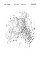
- FIG. 1is a perspective illustration of a riding exerciser of the invention in a use configuration
- FIG. 2is a perspective view of the riding exerciser of FIG. 1 in a storage configuration
- FIG. 3is a simplified side view of an alternate riding exerciser of the invention.
- FIG. 4is a partial, simplified view of the front portion of an alternate riding exerciser of the invention.
- FIG. 5is a perspective, exploded, simplified view of the front portion of an alternate riding exerciser of the invention.
- FIG. 6is a partial, simplified view of a portion of the riding exerciser of FIGS. 1 and 2;
- FIG. 7is a partial, frontal view of an alternate arrangement of a riding exerciser of the invention.
- a riding exerciser 10having a base 12 for positioning on a support surface.
- the base 12has a front end 14 and a rear end 16.
- the base 12has a guide surface positioned between the front end 14 and the rear end 16.
- the base 12is comprised of a left beam 18 and a right beam 20.
- the upper surfaces 22 and 25 of the left beam 18 and the right beam 20, respectively,have cam surfaces 24 and 26.
- Cam surfaces 24 and 26 shownhave a length 28 and are arcuate. That is, the cam surfaces 24 and 26 each have an outwardly facing arcuate surface 30.
- the cam surfaces 24 and 26are each configured to position the user contact structure such as seat 34 in a desired location and to cause the seat 34 to be positioned at a desired height 37 above the base 12.
- the cam surfacemay adjust in thickness 39 to cause the seat 34 to change in height or to move 36 in downward direction 38 when in the first position of the use configuration.
- the riding exerciser of FIG. 1has user support means for supporting a riding user thereon.
- the user support meansincludes a support member 40 and a user contact structure which is seat 34.
- the support member 40is movably attached to the base 12. More specifically, the support member 40 is attached to the base 12 by a bracket assembly that includes a left bracket 42 and a right bracket 44.
- the left bracket 42is welded or otherwise affixed to the interior surface of the left beam 18, and the right bracket 44 is welded or otherwise affixed to the interior surface of the right beam 20.
- the support member 40has a bushing 46 secured to its lower end 48.
- An axle 50extends through the bushing 46 to provide for rotational movement of the user support means and more particularly the support member 40 from a first position 51 shown in solid in FIG. 1 to a second position 52 shown in dotted line or phantom in FIG. 1.
- a stop 53is welded or otherwise attached to the support member 40 at a location along the length of the support member 40 to fix the first position of the user support means.
- the riding exercise of FIG. 1also includes limb structure 54 that is rotatably attached to the support member 40.
- the limb structure 54has an upper end 56 with handle structure 58 positioned for grasping by a user positioned on the user support means and more particularly the seat 34.
- the handle structure 58is a continuous bar arrangement 60 having a top 62 as well as a left side 64 and a right side 66. With the configuration provided, the user can position his or her hands in various orientations along the arcs of the handle structure 58 to in turn vary the nature of the exercise and the muscles engaged in performing exercise. Other handle arrangements such as a T-handle may be used as desired.
- the limb structure 54 of FIG. 1has guide means for contact and movement along the guide surface.
- the guide meansare here shown to be a right wheel 68 and a left wheel 70 each rotatably mounted to their respective lower ends 72 and 74 of the lower portion 76 of the limb structure 54.
- the wheels 68 and 70are rotatably mounted to move along a respective guide surface.
- the guide surfacemay be the top 25 of the right beam 20 and the top 22 of the left beam 18.
- the guide surfacespecifically includes the surfaces 30 and 32 of the cam surfaces 24 and 26. Therefore, in operation upon movement of the limb structure between a first position and a second position displaced from the first position, the wheels 68 and 70 move along the cam surfaces 30 and 32.
- a pair of foot pedals 78 and 80are also attached at the lower ends 72 and 74 of the limb structure 54.
- the usermay position his or her feet therein in the performance of exercises to urge the limb structure to move from the first position to the second position (shown in phantom in FIG. 1) by exerting a pressure or force on the pedals 78 and 80.
- right beam 20 and left beam 18are each fixedly attached, such as by welding, to a front foot 82 that has friction structure 84 and 86 secured to the outward ends thereof for contact with the support surface.
- a rear foot 88is attached such as by welding to the right beam 20 and left beam 18 with similar friction structure 90 and 92 for contact with the support surface.
- the feet 82, 88have width 93 selected to provide the riding exerciser with sufficient sideways stability. That is, the width 93 and the length 94 together provide a foot print to stably support the exerciser 10 on a support surface.
- resistance meansis also seen comprised of a resistance cylinder 96 rotatably connected by a bolt 98 to the support member 40 and by a bushing and bolt structure 100 to the base 12.
- the resistance cylinder 96may be non-adjustable; or it may be of the adjustable variety as more fully described in the parent application hereto Ser. No. 08/382,342 filed Feb. 1, 1995 the specification of which is incorporated herein by reference.
- the limb structureis comprised of a spaced apart right member 102 and a left member 104 interconnected by a stiffener 106.
- the right member 102 and left member 104straddle the support member 40 and are connected thereto through straps 108 and 110 and an interconnecting axle 112 as better seen in FIG. 6. More specifically, the right member 102 and left member 104 are rotatably secured by the interconnecting axle 112 that has a head 114 and a nut 116 threaded thereon in a conventional manner.
- the lower portion 76 of the limb structure 54extends downwardly a preselected distance 118 that is similar to the distance 120 between the limb axle 112 and the support axle 50. That is, the effective length 118 is selected so that upon rotation of the limb structure 54 from a use configuration as shown in solid in FIG. 1 to a stored configuration shown in FIG. 2, the wheels 68 and 70 move to a position proximate the support axle 46.
- the lower portion 76 of the limb structure 54is arcuately shaped so that upon rotation of the limb structure 54 from its use configuration shown in solid in FIG. 1 to a storage configuration shown in FIG. 2, the handle structure 58 may be sufficiently rotated to be positioned proximate the seat 34.
- the riding exerciser 10 disclosedmay be positioned in a use configuration as shown in FIG. 1.
- the exercise machine 10When in the use configuration, the exercise machine 10 may be operated between a first position and a second position. That is, when the limb structure 54 is connected to the support member 40 as shown in FIG. 1, movement of the limb structure 54 from the first position 51 shown in solid to the second position 52, partially shown in phantom or in dotted line, results in simultaneous movement of the support member 40 means from the first position 51 shown in solid in FIG. 1 to the second position 52 partially shown in phantom in FIG. 1.
- the userdismounts from the seat 34 and while dismounted operates the limb structure 54 from the user configuration shown in FIG. 1 and more particularly from the first position 51 shown in solid in FIG. 1 through the second position 52 shown in phantom or dotted line in FIG. 1 to the storage configuration shown in FIG. 2.
- the wheel 70rolls along the cam surface 30 and over the forward edge 124 to a position forward of the cam surface 24 on the top of the left beam 18 and more particularly the surface 22.
- the wheel 68 on the right sidesimilarly moves over the cam surface 32 and onto the surface 25 of the right beam 20.
- the handle structure 58extends rearward and over the seat 34.
- the area 126 (FIG. 1) defined by the right member 102 and the left member 104 as well as the left and right sides 66,68 and the top portion 62is greater than the projected area of the seat 34 so that the seat 34 may fit therethrough. Further, the right member 102 and the left member 104 are spaced apart so that the support member 40 may readily extend upward to a position where it is in contact with the stiffener 106. It may also be noted that the handle structure 58 of the limb structure 54 is arcuate. That is, the handle structure 58 is disposed to be at an angle 128 relative to the right member 102 and left member 104. As so shaped, the handle sturcture 58 fits generally in alignment with the seat 34 and the upper sturcture 35 of the support member 40.
- the right member 102 and the left member 104are not parallel to the beams 18 and 20. That is, the handle structure 58 is in substantial alignment to the beams 18 and 20.
- the lower portion 76 and the middle portion 77 of the limb structure 54is positioned close to and, what is here defined as, in general alignment with the right beam 20 and the left beam 18.
- the lower portion 76angulates down towards the beams 18 and 20 and thereby remains in contact with the upper surfaces 22 and 25.
- the weight of the support member 40 and seat 34 through the axle 112urges the limb structure 54 downward and about the support member 40 and seat 34.
- the wheels 68 and 70act as a fulcrum.
- riding exerciser 10When positioned in the storage position, it can be seen that riding exerciser 10 is compact and therefore readily storable in a closet, potentially under a bed or even behind a piece of furniture. It may further be noted that the riding exerciser 10 of FIG. 2 may be assembled and shipped in a substantially assembled condition to minimize assembly difficulties for the purchaser without use of an excessively large box with all the costs attendant to the use of a large box.
- the userneed only move the handle structure 58 upward thereby causing the rollers 70 and 68 to proceed up over their respective lips, such as edge 124 at one end of the cam surfaces 30 and 32.
- the user support means and more particularly the support member 40is moved upward and into the use configuration for operation as shown in FIG. 1.
- the usermay find operation or manipulation of the limb structure 54 to be facilitated by placing the user's foot on the rear foot 88 to stabilize the unit when moving from the storage configuration to the use configuration.
- the usermay also find it convenient to place the toe or foot of the user on the forward foot 82 when otherwise moving the riding exerciser 10 between the use configuration and the storage configuration.
- FIG. 3shows an alternate configuration of the riding exerciser in which the base 140 has a left beam 142 and a right beam not shown.
- the left beam 142 and the right beamare each secured to a front foot 144 and a rear foot 146.
- User support meansis here shown to include a support member 147 rotatably attached by an axle 148 to bracket structure 150 comparable to the bracket structure 42 and 44 shown in FIGS. 1 and 2.
- the user support meansincludes a seat 152 which is secured to the support member 146 by a plurality of screws or bolts 154 and 156.
- Limb structure 158is comprised of a left member 160 and a right member (not shown) extending upwardly to a handle portion 162.
- the limb structure 158is rotatably secured by a limb axle 164 to a bracket or strap structure comparable to strap structure 110 and 108 shown in FIGS. 1 and 2.
- the strap structure of FIG. 3includes a left strap 166 and right strap (not shown) that are secured to the support member 146 to extend generally upward therefrom.
- the limb structure 158also includes a lower portion 168 with a left wheel 170 rotatably secured about an axle 172 to the distal end 174 of the lower portion 168.
- a right wheel(not shown) is similarly mounted to the distal end of the right member (not shown).
- a foot pedal 176is also secured by the same axle 172 at the distal end 174 of the lower portion 168 of the limb structure 158.
- a foot pedalis similarly secured to the right distal end of the right member.
- a stophere shown in the form of a bar 178, is welded or otherwise secured to the underside 180 of the support member 146. It extends outwardly therefrom a distance sufficient to engage the lower portion 168 of the left member 160 as well as the lower portion of the right member (not shown).
- the stop 178is positioned along the underside 180 to fix the first position of the riding exerciser.
- the second position of the riding exerciserin which the limb structure 158 is rotated towards 182 the user positioned on the seat 152 and in which the support member 146 rotates towards the limb structure 158, is limited by the user on the seat 152.
- further rotation of the limb structure 158 through the second position and thereafter continuing to urge the limb structure to moveplaces the limb structure as well as the user support structure in the storage configuration comparable to the storage configuration shown in FIG. 2.
- a resistance cylinder 186is connected at its lower end 188 by a bushing 190 to a lower bracket 192 by a bolt 194.
- the other end and more particularly the piston 196also has a bushing 198 associated therewith which is rotatably connected by a bolt 200 to a bracket 202.
- the cylinder 186resists movement of the limb structure 158 between the first position and the second position. It also resists movement of the limb structure 158 from its use configuration as shown in FIG. 3 to the storage configuration comparable to that shown in FIG. 2.
- upper surface 204 of the left beam 142 as well as the upper surface of the corresponding right beamfunction as the cam surface for movement of the left wheel 170 and the right wheel during operation of the riding exerciser between a first position and the second position as well as during reorientation between the use configuration shown in FIG. 3 and the storage configuration similar to the storage configuration of FIG. 2.
- bushings 190 and 198are secured to their respective brackets 202 and 192 by bolts 200 and 194 or other comparable structure including pins, axles or the like.
- the bracket 192 shown in FIG. 3is attached to the inside surface of the beam 142.
- a corresponding bracket, not shown,is attached to the inside surface of the right beam, not here shown. Spacers may be used to extend between the right bracket, not shown, and the bracket 192 to centrally position the bushing 190 on the pin or bolt 194.
- FIG. 4a partial side view of an alternate configuration is shown in which the left beam 210 has cam structure 212 secured thereto.
- the left beam 210 and a right beam(not shown) are connected to a forward foot 214.
- a left bracket 216 and a right bracket(not shown) are secured to the forward foot 214 to extend upwardly and forwardly therefrom.
- the support member 218is rotatably secured to the left bracket 216 and right bracket, not shown, by an axle 219 which may be a bolt, a pin or other comparable structure which functions as an axle.
- An extension 220is secured to the forward foot 214 to extend away therefrom.
- the wheel 222 secured to the distal end 224 of the right support 226 of the limb structure 228proceeds forwardly past the forward foot 214 onto the extension 220.
- the additional length of the left beam 210 provided by the extension 220produces a different geometric configuration in which the angle 230 between the lower portion 232 and the upper portion of the right support 226 is increased. That is, the angle 230 was made to be a larger obtuse angle thereby minimizing the overall height or thickness of the box into which an assembled riding exerciser of FIG. 4 will be placed for shipment.
- limb structure 228 and more particularly the left upright member 236 and the right upright memberare secured to the support member 218 by bracket 234 by a limb axle 236.
- a stop 238is also provided to define the first position when the machine is placed in the use configuration comparable to that shown in FIGS. 1 and 3.
- the resistance structureis not here shown for simplification.
- FIG. 5the forward portion of a riding exerciser is shown with compressive resistance structure associated with the bolt 258 which functions as an axle.
- a front foot 240has a right beam 246 and a left beam 244 both secured thereto.
- a right bracket 248 and a left bracket 250are each secured to their respective right beam 246 and left beam 244.
- the brackets 248 and 250each have a respective aperture 252 and 256 formed therein to receive a bolt 258.
- the bolt 258extends through the apertures 252 and 256 as well as an aperture 249 in bushing 251 which is on the front end of the support member 253 comparable to a support member 40.
- the head 260 of the bolt 258abuts a thrust washer 264.
- the thrust washerhas tongue 266 which registers with slot 268 to prevent rotation of the washer 264 in operation.
- the washer 264has the aperture 262 and the aperture 249 is formed in the bushing 251 to receive the bolt 258.
- a key 255inserts into notch 257 and a notch 258 formed in bolt 258 to lock the bushing 251 to the bolt 259 and to provide for rotation of the bolt 258 upon movement of the support member 253.
- a friction disk 270may have any one or more of a plurality of resistance pads 272 secured to one surface thereof to interface with a disk 274 positioned to interface therewith.
- the disk 274is locked to knob 276 to rotate with the knob 276 and the bolt 258.
- the knob 276 with a handle 278is threadedly engageable with the threads 280 on the end of the bolt 258.
- the useroperates the handle 278 in order to compress the disk 274 against the friction disk 270 and the pads 272 to increase the compression and, in turn, the resistance of rotation of the bolt 258 which is secured to the bushing 251.
- FIG. 7shows an alternate configuration of riding exerciser in which the left member 290 and the right member 292 are shown attached by a bolt 294 to upright brackets 296 and 298 which are welded to the support member 300.
- the bolt 294functions as a limb axle to which compressive resistive structure is associated.
- the bolt 294has a threaded head end 302.
- the knob 303has a threaded aperture 305 sized to threadedly engage the head end 302. Upon rotation, the inside surface 309 of the knob 303 presses against a washer 304.
- the bolt 294extends through apertures formed in the upright 290 and the upright 292 as well as through the brackets 296 and 298 for interconnection with an end cap 306.
- the end cap 306urges plate 308 against the friction pads 312 of disc 310.
- the disc 310is held from rotation by a slot 314 formed in the right member 292 to register with a corresponding tab 316 on the disc 310.
- the usermay thus increase the pressure on the friction pads 312 to in turn increase the resistance to rotation of the bolt 294 and in turn increase the resistance to rotation of the limb member and the support member 300.
- the bolt 294has a threaded aperture 320 formed in a flattened portion 322 at the end 324.
- the flattened portion 322registers with an aperture 326 formed in the end cap 306.
- a set screw 328may be operated to threadedly engage the aperture 320 to in turn secure the end cap 306 to the bolt 294.
- the end cap 306also has a slot 330 which mates with a tap 332 of the plate 308.
- rotation of the left upright 290 and right upright 292causes relative motion between the disc 310 and the plate 308.
- the resulting frictionis regulated by the compressive forces imposed by operation of either handle 318 or 319. The friction in turn resists rotation not only of the uprights 290 and 292 but in turn the support member 300.
- the machines of FIGS. 5 and 7may be operated by simply rotating the handles 318 or 319 and 278 to vary the resistance and in turn vary the degree of difficulty of the exercise.
- the useroperates the resistance cylinder to vary the resistance of the cylinder during the course of performance of the exercise.
Landscapes
- Health & Medical Sciences (AREA)
- General Health & Medical Sciences (AREA)
- Physical Education & Sports Medicine (AREA)
- Life Sciences & Earth Sciences (AREA)
- Biophysics (AREA)
- Orthopedic Medicine & Surgery (AREA)
- Cardiology (AREA)
- Vascular Medicine (AREA)
- Rehabilitation Tools (AREA)
- Transplanting Machines (AREA)
Abstract
Description
Claims (11)
Priority Applications (1)
| Application Number | Priority Date | Filing Date | Title |
|---|---|---|---|
| US08/594,846US5695435A (en) | 1995-02-01 | 1996-01-31 | Collapsible rider exerciser |
Applications Claiming Priority (2)
| Application Number | Priority Date | Filing Date | Title |
|---|---|---|---|
| US08/382,342US5695434A (en) | 1995-02-01 | 1995-02-01 | Riding-type exercise machine |
| US08/594,846US5695435A (en) | 1995-02-01 | 1996-01-31 | Collapsible rider exerciser |
Related Parent Applications (1)
| Application Number | Title | Priority Date | Filing Date |
|---|---|---|---|
| US08/382,342Continuation-In-PartUS5695434A (en) | 1995-02-01 | 1995-02-01 | Riding-type exercise machine |
Publications (1)
| Publication Number | Publication Date |
|---|---|
| US5695435Atrue US5695435A (en) | 1997-12-09 |
Family
ID=23508530
Family Applications (2)
| Application Number | Title | Priority Date | Filing Date |
|---|---|---|---|
| US08/382,342Expired - LifetimeUS5695434A (en) | 1995-02-01 | 1995-02-01 | Riding-type exercise machine |
| US08/594,846Expired - LifetimeUS5695435A (en) | 1995-02-01 | 1996-01-31 | Collapsible rider exerciser |
Family Applications Before (1)
| Application Number | Title | Priority Date | Filing Date |
|---|---|---|---|
| US08/382,342Expired - LifetimeUS5695434A (en) | 1995-02-01 | 1995-02-01 | Riding-type exercise machine |
Country Status (2)
| Country | Link |
|---|---|
| US (2) | US5695434A (en) |
| CA (1) | CA2150593C (en) |
Cited By (68)
| Publication number | Priority date | Publication date | Assignee | Title |
|---|---|---|---|---|
| US6328325B1 (en)* | 2000-06-13 | 2001-12-11 | Charles Greenwood | Teamwork and strength training apparatus |
| US6923749B1 (en) | 2001-01-31 | 2005-08-02 | Barry Stewart Smith | Full-body accordion-motion exercise machine |
| US20060217240A1 (en)* | 2005-03-25 | 2006-09-28 | Ann White | Exercise apparatus for full figured individuals |
| US20080182732A1 (en)* | 2003-08-04 | 2008-07-31 | Hoist Fitness Systems, Inc. | Upper back exercise machine with self-aligning pivoting user support |
| US20080280731A1 (en)* | 2007-05-08 | 2008-11-13 | Icon Health & Fitness, Inc. | Elliptical exercise machine with adjustable foot motion |
| USD588655S1 (en)* | 2007-05-14 | 2009-03-17 | Icon Ip, Inc. | Rider-type exercise seat assembly |
| US7618350B2 (en) | 2007-06-04 | 2009-11-17 | Icon Ip, Inc. | Elliptical exercise machine with adjustable ramp |
| USD609288S1 (en) | 2009-05-04 | 2010-02-02 | Poonam Khubani | Rider exerciser |
| US7658698B2 (en) | 2006-08-02 | 2010-02-09 | Icon Ip, Inc. | Variable stride exercise device with ramp |
| US7717828B2 (en) | 2006-08-02 | 2010-05-18 | Icon Ip, Inc. | Exercise device with pivoting assembly |
| US7736279B2 (en)* | 2007-02-20 | 2010-06-15 | Icon Ip, Inc. | One-step foldable elliptical exercise machine |
| US7740563B2 (en) | 2004-08-11 | 2010-06-22 | Icon Ip, Inc. | Elliptical exercise machine with integrated anaerobic exercise system |
| US7766797B2 (en) | 2004-08-11 | 2010-08-03 | Icon Ip, Inc. | Breakaway or folding elliptical exercise machine |
| USD622788S1 (en) | 2009-05-04 | 2010-08-31 | Poonam Khubani | Rider exerciser |
| US7901335B2 (en) | 2003-08-04 | 2011-03-08 | Hoist Fitness Systems, Inc. | Multi-station exercise machine |
| US7938760B1 (en) | 2008-10-17 | 2011-05-10 | Hoist Fitness Systems, Inc. | Exercise machine with lifting arm |
| US7981010B1 (en) | 2003-08-04 | 2011-07-19 | Hoist Fitness Systems, Inc. | Exercise machine with multi-function user engagement device |
| US7993251B1 (en) | 2003-08-04 | 2011-08-09 | Hoist Fitness Systems, Inc. | Pectoral fly exercise machine |
| US8177693B2 (en) | 2010-02-25 | 2012-05-15 | Hoist Fitness Systems, Inc. | Calf exercise machine with rocking user support |
| US20120252642A1 (en)* | 2011-04-01 | 2012-10-04 | Yi-Tzu Chen | Multi-functional linked fitness equipment |
| US8562496B2 (en) | 2010-03-05 | 2013-10-22 | Hoist Fitness Systems, Inc. | Thigh exercise machine with rocking user support |
| US8734304B2 (en) | 2010-03-04 | 2014-05-27 | Hoist Fitness Systems, Inc. | Low back exercise machine with rocking user support |
| US20180117383A1 (en)* | 2016-11-01 | 2018-05-03 | Icon Health & Fitness, Inc. | Drop-in Pivot Configuration for Stationary Bike |
| US10071298B1 (en)* | 2016-04-04 | 2018-09-11 | Lee B. McCormack | Workout apparatus for simulating user movement patterns in bicycle sports |
| US10201727B2 (en) | 2001-03-30 | 2019-02-12 | Nautilus, Inc. | Exercise machine |
| US10449416B2 (en) | 2015-08-26 | 2019-10-22 | Icon Health & Fitness, Inc. | Strength exercise mechanisms |
| US10493349B2 (en) | 2016-03-18 | 2019-12-03 | Icon Health & Fitness, Inc. | Display on exercise device |
| US10561894B2 (en) | 2016-03-18 | 2020-02-18 | Icon Health & Fitness, Inc. | Treadmill with removable supports |
| US10625137B2 (en) | 2016-03-18 | 2020-04-21 | Icon Health & Fitness, Inc. | Coordinated displays in an exercise device |
| US10625114B2 (en) | 2016-11-01 | 2020-04-21 | Icon Health & Fitness, Inc. | Elliptical and stationary bicycle apparatus including row functionality |
| US10702739B1 (en)* | 2016-04-04 | 2020-07-07 | Lee B McCormack | Workout apparatus for simulating user movement patterns in bicycle sports |
| US10709925B2 (en) | 2013-03-14 | 2020-07-14 | Icon Health & Fitness, Inc. | Strength training apparatus |
| US10758767B2 (en) | 2013-12-26 | 2020-09-01 | Icon Health & Fitness, Inc. | Resistance mechanism in a cable exercise machine |
| US10786706B2 (en) | 2018-07-13 | 2020-09-29 | Icon Health & Fitness, Inc. | Cycling shoe power sensors |
| US10864407B2 (en) | 2016-03-18 | 2020-12-15 | Icon Health & Fitness, Inc. | Coordinated weight selection |
| US10918905B2 (en) | 2016-10-12 | 2021-02-16 | Icon Health & Fitness, Inc. | Systems and methods for reducing runaway resistance on an exercise device |
| US10940360B2 (en) | 2015-08-26 | 2021-03-09 | Icon Health & Fitness, Inc. | Strength exercise mechanisms |
| US10953305B2 (en) | 2015-08-26 | 2021-03-23 | Icon Health & Fitness, Inc. | Strength exercise mechanisms |
| US10994173B2 (en) | 2016-05-13 | 2021-05-04 | Icon Health & Fitness, Inc. | Weight platform treadmill |
| US11000730B2 (en) | 2018-03-16 | 2021-05-11 | Icon Health & Fitness, Inc. | Elliptical exercise machine |
| US11033777B1 (en) | 2019-02-12 | 2021-06-15 | Icon Health & Fitness, Inc. | Stationary exercise machine |
| US11058914B2 (en) | 2016-07-01 | 2021-07-13 | Icon Health & Fitness, Inc. | Cooling methods for exercise equipment |
| US11058913B2 (en) | 2017-12-22 | 2021-07-13 | Icon Health & Fitness, Inc. | Inclinable exercise machine |
| US11187285B2 (en) | 2017-12-09 | 2021-11-30 | Icon Health & Fitness, Inc. | Systems and methods for selectively rotationally fixing a pedaled drivetrain |
| USD944339S1 (en)* | 2021-01-22 | 2022-02-22 | Sailvan Times Co., Ltd. | Rowing machine |
| US11298577B2 (en) | 2019-02-11 | 2022-04-12 | Ifit Inc. | Cable and power rack exercise machine |
| US11326673B2 (en) | 2018-06-11 | 2022-05-10 | Ifit Inc. | Increased durability linear actuator |
| US11451108B2 (en) | 2017-08-16 | 2022-09-20 | Ifit Inc. | Systems and methods for axial impact resistance in electric motors |
| US11534654B2 (en) | 2019-01-25 | 2022-12-27 | Ifit Inc. | Systems and methods for an interactive pedaled exercise device |
| US11534651B2 (en) | 2019-08-15 | 2022-12-27 | Ifit Inc. | Adjustable dumbbell system |
| US11673036B2 (en) | 2019-11-12 | 2023-06-13 | Ifit Inc. | Exercise storage system |
| US11700905B2 (en) | 2014-03-10 | 2023-07-18 | Ifit Inc. | Pressure sensor to quantify work |
| USD997266S1 (en)* | 2021-03-01 | 2023-08-29 | Sculpted Partners LLC | Manual exercise apparatus |
| US11794070B2 (en) | 2019-05-23 | 2023-10-24 | Ifit Inc. | Systems and methods for cooling an exercise device |
| US11850497B2 (en) | 2019-10-11 | 2023-12-26 | Ifit Inc. | Modular exercise device |
| US11878199B2 (en) | 2021-02-16 | 2024-01-23 | Ifit Inc. | Safety mechanism for an adjustable dumbbell |
| US11931621B2 (en) | 2020-03-18 | 2024-03-19 | Ifit Inc. | Systems and methods for treadmill drift avoidance |
| US11951377B2 (en) | 2020-03-24 | 2024-04-09 | Ifit Inc. | Leaderboard with irregularity flags in an exercise machine system |
| US12029935B2 (en) | 2021-08-19 | 2024-07-09 | Ifit Inc. | Adjustment mechanism for an adjustable kettlebell |
| US12029961B2 (en) | 2020-03-24 | 2024-07-09 | Ifit Inc. | Flagging irregularities in user performance in an exercise machine system |
| US12176009B2 (en) | 2021-12-30 | 2024-12-24 | Ifit Inc. | Systems and methods for synchronizing workout equipment with video files |
| US12219201B2 (en) | 2021-08-05 | 2025-02-04 | Ifit Inc. | Synchronizing video workout programs across multiple devices |
| US12263371B2 (en) | 2021-04-27 | 2025-04-01 | Ifit Inc. | Devices, systems, and methods for rotating a tread belt in two directions |
| US12280294B2 (en) | 2021-10-15 | 2025-04-22 | Ifit Inc. | Magnetic clutch for a pedaled drivetrain |
| US12350547B2 (en) | 2022-02-28 | 2025-07-08 | Ifit Inc. | Devices, systems, and methods for moving a movable step through a transition zone |
| US12350573B2 (en) | 2021-04-27 | 2025-07-08 | Ifit Inc. | Systems and methods for cross-training on exercise devices |
| US12409375B2 (en) | 2022-03-18 | 2025-09-09 | Ifit Inc. | Systems and methods for haptic simulation in incline exercise devices |
| US12433815B2 (en) | 2020-10-02 | 2025-10-07 | Ifit Inc. | Massage roller with pressure sensors |
Families Citing this family (20)
| Publication number | Priority date | Publication date | Assignee | Title |
|---|---|---|---|---|
| US7654940B2 (en) | 2006-09-06 | 2010-02-02 | Hoist Fitness Systems, Inc. | Arm exercise machine with self-aligning pivoting user support |
| US7549949B2 (en) | 2003-08-04 | 2009-06-23 | Hoist Fitness Systems, Inc. | Chest press exercise machine with self-aligning pivoting user support |
| US7794371B2 (en) | 2003-08-04 | 2010-09-14 | Hoist Fitness Systems, Inc. | Lat exercise machine with self-aligning pivoting user support |
| US7563209B2 (en) | 2006-09-05 | 2009-07-21 | Hoist Fitness Systems, Inc. | Leg exercise machine with self-aligning pivoting seat |
| US7335140B2 (en)* | 2003-10-31 | 2008-02-26 | Hoist Fitness Systems | Triceps dip exercise machine |
| US7361125B2 (en)* | 2003-11-03 | 2008-04-22 | Hoist Fitness Systems, Inc. | Rigid arm pull down exercise machine |
| US7331911B2 (en)* | 2003-11-03 | 2008-02-19 | Hoist Fitness Systems | Shoulder press exercise machine |
| US7670269B2 (en) | 2006-09-05 | 2010-03-02 | Hoist Fitness Systems, Inc. | Chest press exercise machine with self-aligning pivoting user support |
| GB0810889D0 (en)* | 2007-08-24 | 2008-07-23 | Evans Graham | Exercise apparatus |
| US7789806B2 (en)* | 2008-07-02 | 2010-09-07 | Chung-Chin Yang | Scissors-like exercising apparatus |
| US8821354B1 (en)* | 2012-02-07 | 2014-09-02 | Hazem Tabahi | Abdominal muscle and cycle workout machine |
| US9345948B2 (en) | 2012-10-19 | 2016-05-24 | Todd Martin | System for providing a coach with live training data of an athlete as the athlete is training |
| WO2015191445A1 (en) | 2014-06-09 | 2015-12-17 | Icon Health & Fitness, Inc. | Cable system incorporated into a treadmill |
| CN107921308B (en) | 2015-08-28 | 2020-04-10 | 爱康保健健身有限公司 | Sleeve in body-building apparatus |
| US10441840B2 (en) | 2016-03-18 | 2019-10-15 | Icon Health & Fitness, Inc. | Collapsible strength exercise machine |
| US10661114B2 (en) | 2016-11-01 | 2020-05-26 | Icon Health & Fitness, Inc. | Body weight lift mechanism on treadmill |
| UY4583S (en) | 2017-02-20 | 2018-03-23 | Uribe Fernando Humberto Mercenari | FOLDING EXERCISE EQUIPMENT WITH RESISTANCE BANDS, SEAT AND REVERSIBLE GRIPS |
| TWI692367B (en)* | 2019-01-09 | 2020-05-01 | 臺灣輔康醫療器材股份有限公司 | Sit to stand functional exerciser |
| US11083662B2 (en)* | 2019-08-14 | 2021-08-10 | Eduardo Marti | Pivoting lower limb therapy device |
| US11517787B2 (en)* | 2021-03-25 | 2022-12-06 | Ping-Hung Chang | Exercise device for alternating movement of arms and legs |
Citations (23)
| Publication number | Priority date | Publication date | Assignee | Title |
|---|---|---|---|---|
| US2145940A (en)* | 1937-02-08 | 1939-02-07 | Harold J Marlowe | Exercising machine |
| US2642288A (en)* | 1949-08-01 | 1953-06-16 | Pearl B Bell | Exercise machine |
| US3446503A (en)* | 1967-03-17 | 1969-05-27 | Donald C Lawton | Pull type exercising device |
| US4452448A (en)* | 1982-03-05 | 1984-06-05 | Ausherman Harry S | Exercising machine |
| US5178599A (en)* | 1991-02-20 | 1993-01-12 | Scott Edwin R | Bidirectional, synchronous, total body exercise machine |
| US5254067A (en)* | 1990-06-21 | 1993-10-19 | Pacific Fitness Corporation | Recumbent leg exerciser |
| USD344112S (en) | 1992-06-08 | 1994-02-08 | Smith Gary H | Physical exerciser |
| US5299997A (en)* | 1993-08-24 | 1994-04-05 | Paul Chen | Horse-riding type exerciser |
| US5338277A (en)* | 1993-05-11 | 1994-08-16 | Yang Li H | Body building apparatus with a neck massager |
| US5356357A (en)* | 1994-02-24 | 1994-10-18 | Greenmaster Industrial Corp. | Riding exerciser |
| US5366428A (en)* | 1994-03-15 | 1994-11-22 | Liao Nien Yuan | Gymnastic apparatus capable of animating horse riding |
| US5370594A (en)* | 1994-05-16 | 1994-12-06 | Grinblat; Arkady G. | Adjustable and configurable exercise machine |
| USD356128S (en) | 1993-04-20 | 1995-03-07 | Exerhealth, Inc. | Physical exerciser |
| US5421795A (en)* | 1994-11-09 | 1995-06-06 | Chen; Paul | Horse-riding type exerciser |
| US5423731A (en)* | 1994-06-03 | 1995-06-13 | Chen; David | Exercise device with two seats |
| US5429568A (en)* | 1994-07-08 | 1995-07-04 | Chen; Paul | Horse-riding type exerciser |
| US5453066A (en)* | 1995-02-24 | 1995-09-26 | Richter, Jr.; Charles E. | Horse riding type exerciser |
| US5458553A (en)* | 1995-01-03 | 1995-10-17 | Wu; Tien-Lai | Foldable exercise device |
| US5464378A (en)* | 1994-06-27 | 1995-11-07 | Kuo-Ron Lee | Foldable exerciser horse |
| US5478298A (en)* | 1995-02-27 | 1995-12-26 | Chen; Paul | Convertible horse-riding type exerciser |
| US5503608A (en)* | 1995-06-15 | 1996-04-02 | Chang; Ta-Fang | Horse riding type exerciser |
| US5507710A (en)* | 1995-05-16 | 1996-04-16 | Chen; Paul | Adjustable horse-riding type exerciser |
| US5520599A (en)* | 1995-04-14 | 1996-05-28 | Chen; Paul | Horse-riding simulating exerciser having two modes of operation |
Family Cites Families (25)
| Publication number | Priority date | Publication date | Assignee | Title |
|---|---|---|---|---|
| US2470544A (en)* | 1948-09-24 | 1949-05-17 | Joseph D Bell | Exercising device |
| US2714507A (en)* | 1950-09-19 | 1955-08-02 | Norris E Goodrich | Exercising machine |
| US2924456A (en)* | 1957-11-18 | 1960-02-09 | Harold J Miller | Exercising machines |
| DE1516401A1 (en)* | 1965-12-02 | 1969-07-24 | Cykelfabriken Fram Ab | Frame for work machines, especially ergometer apparatus |
| US3759511A (en)* | 1971-03-29 | 1973-09-18 | K Gustafson | Adjustable friction type exercising device |
| FR2151551A5 (en)* | 1971-09-03 | 1973-04-20 | Jouk Leo | |
| IT1035298B (en)* | 1974-04-18 | 1979-10-20 | British Industrial Plastics | RESIN-BASED ADE SIVI MANUFACTURING SYSTEM SI AMINO PLASTI AND APPARATUS AND PROCE APPLICATION DIMENSION |
| US4043552A (en)* | 1975-06-13 | 1977-08-23 | Kerkonian Siragan K | Exerciser seat |
| US3976058A (en)* | 1975-09-12 | 1976-08-24 | Tidwell James H | Physical coordination training device |
| US4188030A (en)* | 1976-10-18 | 1980-02-12 | Repco Limited | Cycle exerciser |
| US4300760A (en)* | 1977-01-12 | 1981-11-17 | Harry Bobroff | Exercise device |
| US4176836A (en)* | 1977-06-21 | 1979-12-04 | Randy Coyle | Variable resistance exercising apparatus and method |
| US4170351A (en)* | 1977-10-06 | 1979-10-09 | Ozbey Ahmet M | Spring-type arm and leg exerciser |
| WO1980000099A1 (en)* | 1978-06-20 | 1980-01-24 | Sumitomo Metal Ind | Method of non-contact supersonic flaw detection and apparatus therefor |
| DE3370140D1 (en)* | 1982-05-25 | 1987-04-16 | Brown Fitzpatrick Lloyd Patent | Convertible exercising apparatus |
| USD277304S (en) | 1982-07-19 | 1985-01-22 | David B. Smith | Rowing machine |
| WO1984000496A1 (en)* | 1982-07-21 | 1984-02-16 | Comdox Pty Ltd | Exercise machine |
| US4684126A (en)* | 1984-08-29 | 1987-08-04 | Pro Form, Inc. | General purpose exercise machine |
| SU1248615A1 (en)* | 1984-09-15 | 1986-08-07 | Всесоюзный Проектно-Технологический И Экспериментально-Конструкторский Институт По Спортивным И Туристским Изделиям | Arrangement for training muscles |
| US4809976A (en)* | 1988-05-17 | 1989-03-07 | Meir Berger | Apparatus for independently exercising arms and legs |
| DE3910704C2 (en)* | 1989-04-03 | 1998-04-09 | Bals Hans G Dipl Ing | Sports and therapy device |
| US5330404A (en)* | 1993-03-01 | 1994-07-19 | Lopeteguy Joe A | Exercise apparatus |
| US5306218A (en)* | 1993-10-15 | 1994-04-26 | Vincent Huang Chen | Rowing exerciser |
| US5342269A (en)* | 1994-01-04 | 1994-08-30 | Richard Huang | Arm oscillating exerciser |
| USD358437S (en) | 1994-02-24 | 1995-05-16 | Greenmaster Industrial Corporation | Riding exerciser |
- 1995
- 1995-02-01USUS08/382,342patent/US5695434A/ennot_activeExpired - Lifetime
- 1995-05-31CACA002150593Apatent/CA2150593C/ennot_activeExpired - Lifetime
- 1996
- 1996-01-31USUS08/594,846patent/US5695435A/ennot_activeExpired - Lifetime
Patent Citations (23)
| Publication number | Priority date | Publication date | Assignee | Title |
|---|---|---|---|---|
| US2145940A (en)* | 1937-02-08 | 1939-02-07 | Harold J Marlowe | Exercising machine |
| US2642288A (en)* | 1949-08-01 | 1953-06-16 | Pearl B Bell | Exercise machine |
| US3446503A (en)* | 1967-03-17 | 1969-05-27 | Donald C Lawton | Pull type exercising device |
| US4452448A (en)* | 1982-03-05 | 1984-06-05 | Ausherman Harry S | Exercising machine |
| US5254067A (en)* | 1990-06-21 | 1993-10-19 | Pacific Fitness Corporation | Recumbent leg exerciser |
| US5178599A (en)* | 1991-02-20 | 1993-01-12 | Scott Edwin R | Bidirectional, synchronous, total body exercise machine |
| USD344112S (en) | 1992-06-08 | 1994-02-08 | Smith Gary H | Physical exerciser |
| USD356128S (en) | 1993-04-20 | 1995-03-07 | Exerhealth, Inc. | Physical exerciser |
| US5338277A (en)* | 1993-05-11 | 1994-08-16 | Yang Li H | Body building apparatus with a neck massager |
| US5299997A (en)* | 1993-08-24 | 1994-04-05 | Paul Chen | Horse-riding type exerciser |
| US5356357A (en)* | 1994-02-24 | 1994-10-18 | Greenmaster Industrial Corp. | Riding exerciser |
| US5366428A (en)* | 1994-03-15 | 1994-11-22 | Liao Nien Yuan | Gymnastic apparatus capable of animating horse riding |
| US5370594A (en)* | 1994-05-16 | 1994-12-06 | Grinblat; Arkady G. | Adjustable and configurable exercise machine |
| US5423731A (en)* | 1994-06-03 | 1995-06-13 | Chen; David | Exercise device with two seats |
| US5464378A (en)* | 1994-06-27 | 1995-11-07 | Kuo-Ron Lee | Foldable exerciser horse |
| US5429568A (en)* | 1994-07-08 | 1995-07-04 | Chen; Paul | Horse-riding type exerciser |
| US5421795A (en)* | 1994-11-09 | 1995-06-06 | Chen; Paul | Horse-riding type exerciser |
| US5458553A (en)* | 1995-01-03 | 1995-10-17 | Wu; Tien-Lai | Foldable exercise device |
| US5453066A (en)* | 1995-02-24 | 1995-09-26 | Richter, Jr.; Charles E. | Horse riding type exerciser |
| US5478298A (en)* | 1995-02-27 | 1995-12-26 | Chen; Paul | Convertible horse-riding type exerciser |
| US5520599A (en)* | 1995-04-14 | 1996-05-28 | Chen; Paul | Horse-riding simulating exerciser having two modes of operation |
| US5507710A (en)* | 1995-05-16 | 1996-04-16 | Chen; Paul | Adjustable horse-riding type exerciser |
| US5503608A (en)* | 1995-06-15 | 1996-04-02 | Chang; Ta-Fang | Horse riding type exerciser |
Non-Patent Citations (19)
| Title |
|---|
| Cover page and p. 35 of Damark catalog dated Jul. 28, 1994 showing Voit s GRAVITY RIDER riding machine.* |
| Cover page and p. 35 of Damark catalog dated Jul. 28, 1994 showing Voit's GRAVITY RIDER riding machine. |
| Cover page of Damark catalog dated Feb. 1996 showing POWER RIDER riding machine.* |
| Cover page of Damark catalog dated May 1995 showing CSA s E FORCE riding machine.* |
| Cover page of Damark catalog dated May 1995 showing CSA's E-FORCE riding machine. |
| Diagram of EXERCYCLE machine.* |
| Exerhealth s HEALTHRIDER Parts Description dated Apr. 26, 1994.* |
| Exerhealth's HEALTHRIDER Parts Description--dated Apr. 26, 1994. |
| Polaroid photographs of EXEROW machine with diagram.* |
| User s Manual for AEROBICRIDER.* |
| User s Manual for CARDIO TRAINER 456 undated.* |
| User s Manual for Guthy Renker Fitness POWER RIDER undated.* |
| User s Manual for Lifestyle CARDIO FIT 1994.* |
| User s Manual for WESLO CARDIOTRAINER 1995.* |
| User's Manual for AEROBICRIDER. |
| User's Manual for CARDIO-TRAINER 456--undated. |
| User's Manual for Guthy-Renker Fitness' POWER RIDER--undated. |
| User's Manual for Lifestyle CARDIO FIT--1994. |
| User's Manual for WESLO CARDIOTRAINER--1995. |
Cited By (105)
| Publication number | Priority date | Publication date | Assignee | Title |
|---|---|---|---|---|
| US6328325B1 (en)* | 2000-06-13 | 2001-12-11 | Charles Greenwood | Teamwork and strength training apparatus |
| US6923749B1 (en) | 2001-01-31 | 2005-08-02 | Barry Stewart Smith | Full-body accordion-motion exercise machine |
| US10201727B2 (en) | 2001-03-30 | 2019-02-12 | Nautilus, Inc. | Exercise machine |
| US7901335B2 (en) | 2003-08-04 | 2011-03-08 | Hoist Fitness Systems, Inc. | Multi-station exercise machine |
| US20080182732A1 (en)* | 2003-08-04 | 2008-07-31 | Hoist Fitness Systems, Inc. | Upper back exercise machine with self-aligning pivoting user support |
| US20080220950A1 (en)* | 2003-08-04 | 2008-09-11 | Hoist Fitness Systems, Inc. | Chest exercise machine with self-aligning pivoting user support |
| US8002679B2 (en)* | 2003-08-04 | 2011-08-23 | Hoist Fitness Systems, Inc. | Chest exercise machine with self-aligning pivoting user support |
| US7993251B1 (en) | 2003-08-04 | 2011-08-09 | Hoist Fitness Systems, Inc. | Pectoral fly exercise machine |
| US7988603B2 (en) | 2003-08-04 | 2011-08-02 | Hoist Fitness Systems, Inc. | Leg press exercise machine with self-aligning pivoting seat |
| US7981010B1 (en) | 2003-08-04 | 2011-07-19 | Hoist Fitness Systems, Inc. | Exercise machine with multi-function user engagement device |
| US7976440B2 (en) | 2003-08-04 | 2011-07-12 | Hoist Fitness Systems, Inc. | Upper back exercise machine with self-aligning pivoting user support |
| US7766797B2 (en) | 2004-08-11 | 2010-08-03 | Icon Ip, Inc. | Breakaway or folding elliptical exercise machine |
| US7740563B2 (en) | 2004-08-11 | 2010-06-22 | Icon Ip, Inc. | Elliptical exercise machine with integrated anaerobic exercise system |
| US7775940B2 (en) | 2004-08-11 | 2010-08-17 | Icon Ip, Inc. | Folding elliptical exercise machine |
| US7909740B2 (en) | 2004-08-11 | 2011-03-22 | Icon Ip, Inc. | Elliptical exercise machine with integrated aerobic exercise system |
| US20060217240A1 (en)* | 2005-03-25 | 2006-09-28 | Ann White | Exercise apparatus for full figured individuals |
| US7658698B2 (en) | 2006-08-02 | 2010-02-09 | Icon Ip, Inc. | Variable stride exercise device with ramp |
| US7717828B2 (en) | 2006-08-02 | 2010-05-18 | Icon Ip, Inc. | Exercise device with pivoting assembly |
| US7736279B2 (en)* | 2007-02-20 | 2010-06-15 | Icon Ip, Inc. | One-step foldable elliptical exercise machine |
| US20080280731A1 (en)* | 2007-05-08 | 2008-11-13 | Icon Health & Fitness, Inc. | Elliptical exercise machine with adjustable foot motion |
| US7674205B2 (en) | 2007-05-08 | 2010-03-09 | Icon Ip, Inc. | Elliptical exercise machine with adjustable foot motion |
| USD588655S1 (en)* | 2007-05-14 | 2009-03-17 | Icon Ip, Inc. | Rider-type exercise seat assembly |
| US7618350B2 (en) | 2007-06-04 | 2009-11-17 | Icon Ip, Inc. | Elliptical exercise machine with adjustable ramp |
| US7938760B1 (en) | 2008-10-17 | 2011-05-10 | Hoist Fitness Systems, Inc. | Exercise machine with lifting arm |
| US10639513B2 (en) | 2008-10-17 | 2020-05-05 | Hoist Fitness Systems, Inc. | Exercise machine with lifting arm |
| US10646739B2 (en) | 2008-10-17 | 2020-05-12 | Hoist Fitness Systems, Inc. | Exercise machine with lifting arm |
| US11000722B2 (en) | 2008-10-17 | 2021-05-11 | Hoist Fitness Systems, Inc. | Exercise machine with lifting arm |
| US11759668B2 (en) | 2008-10-17 | 2023-09-19 | Hoist Fitness Systems, Inc. | Exercise machine with lifting arm |
| US9861850B1 (en) | 2008-10-17 | 2018-01-09 | Hoist Fitness Systems, Inc. | Exercise machine with lifting arm |
| USD609288S1 (en) | 2009-05-04 | 2010-02-02 | Poonam Khubani | Rider exerciser |
| USD622788S1 (en) | 2009-05-04 | 2010-08-31 | Poonam Khubani | Rider exerciser |
| US8177693B2 (en) | 2010-02-25 | 2012-05-15 | Hoist Fitness Systems, Inc. | Calf exercise machine with rocking user support |
| US8734304B2 (en) | 2010-03-04 | 2014-05-27 | Hoist Fitness Systems, Inc. | Low back exercise machine with rocking user support |
| US8562496B2 (en) | 2010-03-05 | 2013-10-22 | Hoist Fitness Systems, Inc. | Thigh exercise machine with rocking user support |
| US20120252642A1 (en)* | 2011-04-01 | 2012-10-04 | Yi-Tzu Chen | Multi-functional linked fitness equipment |
| US8556780B2 (en)* | 2011-04-01 | 2013-10-15 | Yi-Tzu Chen | Multi-functional linked fitness equipment |
| US11338169B2 (en) | 2013-03-14 | 2022-05-24 | IFIT, Inc. | Strength training apparatus |
| US10953268B1 (en) | 2013-03-14 | 2021-03-23 | Icon Health & Fitness, Inc. | Strength training apparatus |
| US10709925B2 (en) | 2013-03-14 | 2020-07-14 | Icon Health & Fitness, Inc. | Strength training apparatus |
| US11878206B2 (en) | 2013-03-14 | 2024-01-23 | Ifit Inc. | Strength training apparatus |
| US10967214B1 (en) | 2013-12-26 | 2021-04-06 | Icon Health & Fitness, Inc. | Cable exercise machine |
| US10758767B2 (en) | 2013-12-26 | 2020-09-01 | Icon Health & Fitness, Inc. | Resistance mechanism in a cable exercise machine |
| US11700905B2 (en) | 2014-03-10 | 2023-07-18 | Ifit Inc. | Pressure sensor to quantify work |
| US10449416B2 (en) | 2015-08-26 | 2019-10-22 | Icon Health & Fitness, Inc. | Strength exercise mechanisms |
| US10953305B2 (en) | 2015-08-26 | 2021-03-23 | Icon Health & Fitness, Inc. | Strength exercise mechanisms |
| US10940360B2 (en) | 2015-08-26 | 2021-03-09 | Icon Health & Fitness, Inc. | Strength exercise mechanisms |
| US10864407B2 (en) | 2016-03-18 | 2020-12-15 | Icon Health & Fitness, Inc. | Coordinated weight selection |
| US11794075B2 (en) | 2016-03-18 | 2023-10-24 | Ifit Inc. | Stationary exercise machine configured to execute a programmed workout with aerobic portions and lifting portions |
| US12029943B2 (en) | 2016-03-18 | 2024-07-09 | Ifit Inc. | Stationary exercise machine configured to execute a programmed workout with aerobic portions and lifting portions |
| US12023549B2 (en) | 2016-03-18 | 2024-07-02 | Ifit Inc. | Stationary exercise machine configured to execute a programmed workout with aerobic portions and lifting portions |
| US10625137B2 (en) | 2016-03-18 | 2020-04-21 | Icon Health & Fitness, Inc. | Coordinated displays in an exercise device |
| US12029944B2 (en) | 2016-03-18 | 2024-07-09 | Ifit Inc. | Stationary exercise machine configured to execute a programmed workout with aerobic portions and lifting portions |
| US10561894B2 (en) | 2016-03-18 | 2020-02-18 | Icon Health & Fitness, Inc. | Treadmill with removable supports |
| US11013960B2 (en) | 2016-03-18 | 2021-05-25 | Icon Health & Fitness, Inc. | Exercise system including a stationary bicycle and a free weight cradle |
| US10493349B2 (en) | 2016-03-18 | 2019-12-03 | Icon Health & Fitness, Inc. | Display on exercise device |
| US11565148B2 (en) | 2016-03-18 | 2023-01-31 | Ifit Inc. | Treadmill with a scale mechanism in a motor cover |
| US10702739B1 (en)* | 2016-04-04 | 2020-07-07 | Lee B McCormack | Workout apparatus for simulating user movement patterns in bicycle sports |
| US10071298B1 (en)* | 2016-04-04 | 2018-09-11 | Lee B. McCormack | Workout apparatus for simulating user movement patterns in bicycle sports |
| US10994173B2 (en) | 2016-05-13 | 2021-05-04 | Icon Health & Fitness, Inc. | Weight platform treadmill |
| US11779812B2 (en) | 2016-05-13 | 2023-10-10 | Ifit Inc. | Treadmill configured to automatically determine user exercise movement |
| US11058914B2 (en) | 2016-07-01 | 2021-07-13 | Icon Health & Fitness, Inc. | Cooling methods for exercise equipment |
| US10918905B2 (en) | 2016-10-12 | 2021-02-16 | Icon Health & Fitness, Inc. | Systems and methods for reducing runaway resistance on an exercise device |
| US20180117383A1 (en)* | 2016-11-01 | 2018-05-03 | Icon Health & Fitness, Inc. | Drop-in Pivot Configuration for Stationary Bike |
| US10561877B2 (en)* | 2016-11-01 | 2020-02-18 | Icon Health & Fitness, Inc. | Drop-in pivot configuration for stationary bike |
| US10625114B2 (en) | 2016-11-01 | 2020-04-21 | Icon Health & Fitness, Inc. | Elliptical and stationary bicycle apparatus including row functionality |
| US11451108B2 (en) | 2017-08-16 | 2022-09-20 | Ifit Inc. | Systems and methods for axial impact resistance in electric motors |
| US11680611B2 (en) | 2017-12-09 | 2023-06-20 | Ifit Inc. | Systems and methods for selectively rotationally fixing a pedaled drivetrain |
| US11708874B2 (en) | 2017-12-09 | 2023-07-25 | Ifit Inc. | Systems and methods for selectively rotationally fixing a pedaled drivetrain |
| US12270441B2 (en) | 2017-12-09 | 2025-04-08 | Ifit Inc. | Systems and methods for selectively rotationally fixing a pedaled drivetrain |
| US11187285B2 (en) | 2017-12-09 | 2021-11-30 | Icon Health & Fitness, Inc. | Systems and methods for selectively rotationally fixing a pedaled drivetrain |
| US11058913B2 (en) | 2017-12-22 | 2021-07-13 | Icon Health & Fitness, Inc. | Inclinable exercise machine |
| US11596830B2 (en) | 2018-03-16 | 2023-03-07 | Ifit Inc. | Elliptical exercise machine |
| US11000730B2 (en) | 2018-03-16 | 2021-05-11 | Icon Health & Fitness, Inc. | Elliptical exercise machine |
| US11326673B2 (en) | 2018-06-11 | 2022-05-10 | Ifit Inc. | Increased durability linear actuator |
| US12005315B2 (en) | 2018-07-13 | 2024-06-11 | Ifit Inc. | Cycling shoe power sensors |
| US10786706B2 (en) | 2018-07-13 | 2020-09-29 | Icon Health & Fitness, Inc. | Cycling shoe power sensors |
| US11534654B2 (en) | 2019-01-25 | 2022-12-27 | Ifit Inc. | Systems and methods for an interactive pedaled exercise device |
| US11298577B2 (en) | 2019-02-11 | 2022-04-12 | Ifit Inc. | Cable and power rack exercise machine |
| US11642564B2 (en) | 2019-02-11 | 2023-05-09 | Ifit Inc. | Exercise machine |
| US11452903B2 (en) | 2019-02-11 | 2022-09-27 | Ifit Inc. | Exercise machine |
| US11951358B2 (en) | 2019-02-12 | 2024-04-09 | Ifit Inc. | Encoding exercise machine control commands in subtitle streams |
| US11058918B1 (en) | 2019-02-12 | 2021-07-13 | Icon Health & Fitness, Inc. | Producing a workout video to control a stationary exercise machine |
| US11033777B1 (en) | 2019-02-12 | 2021-06-15 | Icon Health & Fitness, Inc. | Stationary exercise machine |
| US11426633B2 (en) | 2019-02-12 | 2022-08-30 | Ifit Inc. | Controlling an exercise machine using a video workout program |
| US11794070B2 (en) | 2019-05-23 | 2023-10-24 | Ifit Inc. | Systems and methods for cooling an exercise device |
| US11534651B2 (en) | 2019-08-15 | 2022-12-27 | Ifit Inc. | Adjustable dumbbell system |
| US12296247B2 (en) | 2019-10-11 | 2025-05-13 | Ifit Inc. | Modular exercise device |
| US11850497B2 (en) | 2019-10-11 | 2023-12-26 | Ifit Inc. | Modular exercise device |
| US11673036B2 (en) | 2019-11-12 | 2023-06-13 | Ifit Inc. | Exercise storage system |
| US11931621B2 (en) | 2020-03-18 | 2024-03-19 | Ifit Inc. | Systems and methods for treadmill drift avoidance |
| US11951377B2 (en) | 2020-03-24 | 2024-04-09 | Ifit Inc. | Leaderboard with irregularity flags in an exercise machine system |
| US12029961B2 (en) | 2020-03-24 | 2024-07-09 | Ifit Inc. | Flagging irregularities in user performance in an exercise machine system |
| US12433815B2 (en) | 2020-10-02 | 2025-10-07 | Ifit Inc. | Massage roller with pressure sensors |
| USD944339S1 (en)* | 2021-01-22 | 2022-02-22 | Sailvan Times Co., Ltd. | Rowing machine |
| US12239872B2 (en) | 2021-02-16 | 2025-03-04 | Ifit Inc. | Safety mechanism for an adjustable dumbbell |
| US11878199B2 (en) | 2021-02-16 | 2024-01-23 | Ifit Inc. | Safety mechanism for an adjustable dumbbell |
| USD997266S1 (en)* | 2021-03-01 | 2023-08-29 | Sculpted Partners LLC | Manual exercise apparatus |
| US12263371B2 (en) | 2021-04-27 | 2025-04-01 | Ifit Inc. | Devices, systems, and methods for rotating a tread belt in two directions |
| US12350573B2 (en) | 2021-04-27 | 2025-07-08 | Ifit Inc. | Systems and methods for cross-training on exercise devices |
| US12219201B2 (en) | 2021-08-05 | 2025-02-04 | Ifit Inc. | Synchronizing video workout programs across multiple devices |
| US12029935B2 (en) | 2021-08-19 | 2024-07-09 | Ifit Inc. | Adjustment mechanism for an adjustable kettlebell |
| US12280294B2 (en) | 2021-10-15 | 2025-04-22 | Ifit Inc. | Magnetic clutch for a pedaled drivetrain |
| US12176009B2 (en) | 2021-12-30 | 2024-12-24 | Ifit Inc. | Systems and methods for synchronizing workout equipment with video files |
| US12350547B2 (en) | 2022-02-28 | 2025-07-08 | Ifit Inc. | Devices, systems, and methods for moving a movable step through a transition zone |
| US12409375B2 (en) | 2022-03-18 | 2025-09-09 | Ifit Inc. | Systems and methods for haptic simulation in incline exercise devices |
Also Published As
| Publication number | Publication date |
|---|---|
| US5695434A (en) | 1997-12-09 |
| CA2150593A1 (en) | 1996-08-02 |
| CA2150593C (en) | 2001-01-23 |
Similar Documents
| Publication | Publication Date | Title |
|---|---|---|
| US5695435A (en) | Collapsible rider exerciser | |
| US5792027A (en) | Aerobic striding exerciser | |
| US6773022B2 (en) | Step-cycle for exercise, recreation, and transport having telescopically movable pedals | |
| US5743832A (en) | Fitness equipment | |
| USRE39904E1 (en) | Combined elliptical cycling and stepping exerciser | |
| US5284462A (en) | Body exercising apparatus | |
| US5356357A (en) | Riding exerciser | |
| US5833583A (en) | Exerciser having foot supports moving along elliptical path | |
| US5505679A (en) | Recumbent leg and arm stepping exercising apparatus | |
| US6485041B1 (en) | Step-cycle for exercise, recreation, and transport | |
| US6648802B2 (en) | Variable pitch stationary exercise bicycle | |
| US5782722A (en) | Structure of folding collapsible step exerciser | |
| US5129872A (en) | Exercise apparatus | |
| US5299997A (en) | Horse-riding type exerciser | |
| US6648353B1 (en) | Upright step-cycle with elliptical motion pedalling | |
| US8834324B2 (en) | Exercise bicycle with mechanical flywheel brake | |
| US5743833A (en) | Cabinet treadmill with door | |
| US5733229A (en) | Exercise apparatus using body weight resistance | |
| US5342262A (en) | Vertically-disposed exercise machine | |
| US5145481A (en) | Ski exercise machine | |
| US5938568A (en) | Exercise methods and apparatus | |
| US5129873A (en) | Exercise apparatus | |
| US6719665B1 (en) | Step simulator having pace adjustment device | |
| US5906563A (en) | Dual exercise bike | |
| US6616163B2 (en) | Combined skateboard scooter/exerciser |
Legal Events
| Date | Code | Title | Description |
|---|---|---|---|
| AS | Assignment | Owner name:ICON HEALTH & FITNESS, INC., UTAH Free format text:ASSIGNMENT OF ASSIGNORS INTEREST;ASSIGNORS:DALEBOUT, WILLIAM T.;ELLIS, RICHARD BRAD;REEL/FRAME:007859/0262 Effective date:19960130 | |
| STCF | Information on status: patent grant | Free format text:PATENTED CASE | |
| AS | Assignment | Owner name:GENERAL ELECTRIC CAPITAL CORPORATION, INDIVIDUALLY Free format text:SECURITY AGREEMENT;ASSIGNOR:ICON HEALTH & FITNESS, INC.;REEL/FRAME:009396/0718 Effective date:19980511 | |
| AS | Assignment | Owner name:GENERAL ELECTRIC CAPITAL CORPORATION, INDIVIDUALLY Free format text:SECURITY AGREEMENT;ASSIGNOR:ICON HEALTH & FITNESS, INC.;REEL/FRAME:009423/0025 Effective date:19980511 | |
| FEPP | Fee payment procedure | Free format text:PAYOR NUMBER ASSIGNED (ORIGINAL EVENT CODE: ASPN); ENTITY STATUS OF PATENT OWNER: LARGE ENTITY Free format text:PAYER NUMBER DE-ASSIGNED (ORIGINAL EVENT CODE: RMPN); ENTITY STATUS OF PATENT OWNER: LARGE ENTITY | |
| FPAY | Fee payment | Year of fee payment:4 | |
| AS | Assignment | Owner name:GENERAL ELECTRIC CAPITAL CORPORATION, ILLINOIS Free format text:ASSIGNMENT OF ASSIGNORS INTEREST;ASSIGNOR:ICON IP, INC.;REEL/FRAME:012036/0191 Effective date:20010629 Owner name:GENERAL ELECTRIC CAPITAL CORPORATION, ILLINOIS Free format text:SECURITY AGREEMENT;ASSIGNOR:ICON IP, INC.;REEL/FRAME:012036/0191 Effective date:20010629 | |
| AS | Assignment | Owner name:ICON IP, INC., UTAH Free format text:ASSIGNMENT OF ASSIGNORS INTEREST;ASSIGNOR:ICON HEALTH & FITNESS, INC.;REEL/FRAME:012365/0100 Effective date:20010629 | |
| FPAY | Fee payment | Year of fee payment:8 | |
| AS | Assignment | Owner name:ICON IP, INC., UTAH Free format text:RELEASE OF SECURITY INTEREST IN PATENTS;ASSIGNOR:GENERAL ELECTRIC CAPITAL CORPORATION, AS AGENT;REEL/FRAME:016722/0632 Effective date:20051031 | |
| AS | Assignment | Owner name:BANK OF AMERICA, N.A., AS ADMINISTRATIVE AGENT, MASSACHUSETTS Free format text:PATENT COLLATERAL ASSIGNMENT AND SECURITY AGREEMENT;ASSIGNOR:ICON IP, INC.;REEL/FRAME:016735/0410 Effective date:20051031 Owner name:BANK OF AMERICA, N.A., AS ADMINISTRATIVE AGENT,MAS Free format text:PATENT COLLATERAL ASSIGNMENT AND SECURITY AGREEMENT;ASSIGNOR:ICON IP, INC.;REEL/FRAME:016735/0410 Effective date:20051031 Owner name:BANK OF AMERICA, N.A., AS ADMINISTRATIVE AGENT, MA Free format text:PATENT COLLATERAL ASSIGNMENT AND SECURITY AGREEMENT;ASSIGNOR:ICON IP, INC.;REEL/FRAME:016735/0410 Effective date:20051031 | |
| AS | Assignment | Owner name:BACK BAY CAPITAL FUNDING LLC, MASSACHUSETTS Free format text:SECURITY AGREEMENT;ASSIGNOR:ICON IP, INC.;REEL/FRAME:016844/0452 Effective date:20051031 | |
| AS | Assignment | Owner name:BANK OF AMERICA, N.A., AS ADMINISTRATIVE AGENT, CA Free format text:PATENT COLLATERAL ASSIGNMENT AND SECURITY AGREEMENT;ASSIGNOR:ICON IP, INC.;REEL/FRAME:020666/0637 Effective date:20070906 Owner name:ICON IP, INC., UTAH Free format text:RELEASE OF SECURITY INTEREST;ASSIGNOR:BACK BAY CAPITAL FUNDING LLC;REEL/FRAME:020666/0617 Effective date:20070906 | |
| FPAY | Fee payment | Year of fee payment:12 | |
| AS | Assignment | Owner name:ICON IP, INC., A DELAWARE CORPORATION, UTAH Free format text:RELEASE OF SECURITY INTEREST;ASSIGNOR:BANK OF AMERICA, N.A., AS ADMINISTRATIVE AGENT;REEL/FRAME:025105/0106 Effective date:20100820 | |
| AS | Assignment | Owner name:BANK OF AMERICA, N.A., AS ADMINISTRATIVE AGENT, MA Free format text:SECURITY INTEREST;ASSIGNORS:ICON HEALTH & FITNESS, INC., A DELAWARE CORPORATION;HF HOLDINGS, INC., A DELAWARE CORPORATION;ICON INTERNATIONAL HOLDINGS, INC., A DELAWARE CORPORATION;AND OTHERS;REEL/FRAME:024953/0310 Effective date:20100729 | |
| AS | Assignment | Owner name:WILMINGTON TRUST FSB, AS COLLATERAL AGENT, MINNESO Free format text:SECURITY AGREEMENT;ASSIGNORS:ICON HEALTH & FITNESS, INC., A DELAWARE CORPORATION;ICON INTERNATIONAL HOLDINGS, INC., A DELAWARE CORPORATION;UNIVERSAL TECHNICAL SERVICES, A UTAH CORPORATION;AND OTHERS;REEL/FRAME:025309/0683 Effective date:20101008 | |
| AS | Assignment | Owner name:ICON IP, INC., UTAH Free format text:RELEASE OF SECURITY INTEREST;ASSIGNOR:BANK OF AMERICA, N.A., AS ADMINISTRATIVE AGENT;REEL/FRAME:025304/0570 Effective date:20100820 | |
| AS | Assignment | Owner name:ICON HEALTH & FITNESS, INC., UTAH Free format text:ASSIGNMENT OF ASSIGNORS INTEREST;ASSIGNOR:ICON IP, INC.;REEL/FRAME:034650/0013 Effective date:20141216 | |
| AS | Assignment | Owner name:BANK OF AMERICA, N.A., AS ADMINISTRATIVE AGENT, MA Free format text:SECURITY AGREEMENT;ASSIGNORS:ICON HEALTH & FITNESS, INC.;ICON IP, INC.;REEL/FRAME:036104/0833 Effective date:20150710 | |
| AS | Assignment | Owner name:ICON HEALTH & FITNESS, INC, UTAH Free format text:RELEASE OF SECURITY INTEREST IN PATENTS;ASSIGNOR:BANK OF AMERICA, N.A., ACTING IN ITS CAPACITY AS AGENT FOR THE LENDERS;REEL/FRAME:039584/0575 Effective date:20160803 Owner name:HF HOLDINGS, INC., UTAH Free format text:RELEASE OF SECURITY INTEREST IN PATENTS;ASSIGNOR:BANK OF AMERICA, N.A., ACTING IN ITS CAPACITY AS AGENT FOR THE LENDERS;REEL/FRAME:039584/0886 Effective date:20160803 Owner name:ICON IP, INC., UTAH Free format text:RELEASE OF SECURITY INTEREST IN PATENTS;ASSIGNOR:BANK OF AMERICA, N.A., ACTING IN ITS CAPACITY AS AGENT FOR THE LENDERS;REEL/FRAME:039584/0886 Effective date:20160803 Owner name:ICON - ALTRA LLC, UTAH Free format text:RELEASE OF SECURITY INTEREST IN PATENTS;ASSIGNOR:BANK OF AMERICA, N.A., ACTING IN ITS CAPACITY AS AGENT FOR THE LENDERS;REEL/FRAME:039584/0886 Effective date:20160803 Owner name:UNIVERSAL TECHNICAL SERVICES, UTAH Free format text:RELEASE OF SECURITY INTEREST IN PATENTS;ASSIGNOR:BANK OF AMERICA, N.A., ACTING IN ITS CAPACITY AS AGENT FOR THE LENDERS;REEL/FRAME:039584/0886 Effective date:20160803 Owner name:ICON INTERNATIONAL HOLDINGS, INC., UTAH Free format text:RELEASE OF SECURITY INTEREST IN PATENTS;ASSIGNOR:BANK OF AMERICA, N.A., ACTING IN ITS CAPACITY AS AGENT FOR THE LENDERS;REEL/FRAME:039584/0575 Effective date:20160803 Owner name:ICON IP, INC., UTAH Free format text:RELEASE OF SECURITY INTEREST IN PATENTS;ASSIGNOR:BANK OF AMERICA, N.A., ACTING IN ITS CAPACITY AS AGENT FOR THE LENDERS;REEL/FRAME:039584/0575 Effective date:20160803 Owner name:HF HOLDINGS, INC., UTAH Free format text:RELEASE OF SECURITY INTEREST IN PATENTS;ASSIGNOR:BANK OF AMERICA, N.A., ACTING IN ITS CAPACITY AS AGENT FOR THE LENDERS;REEL/FRAME:039584/0575 Effective date:20160803 Owner name:ICON INTERNATIONAL HOLDINGS, INC., UTAH Free format text:RELEASE OF SECURITY INTEREST IN PATENTS;ASSIGNOR:BANK OF AMERICA, N.A., ACTING IN ITS CAPACITY AS AGENT FOR THE LENDERS;REEL/FRAME:039584/0886 Effective date:20160803 Owner name:UNIVERSAL TECHNICAL SERVICES, UTAH Free format text:RELEASE OF SECURITY INTEREST IN PATENTS;ASSIGNOR:BANK OF AMERICA, N.A., ACTING IN ITS CAPACITY AS AGENT FOR THE LENDERS;REEL/FRAME:039584/0575 Effective date:20160803 Owner name:ICON - ALTRA LLC, UTAH Free format text:RELEASE OF SECURITY INTEREST IN PATENTS;ASSIGNOR:BANK OF AMERICA, N.A., ACTING IN ITS CAPACITY AS AGENT FOR THE LENDERS;REEL/FRAME:039584/0575 Effective date:20160803 Owner name:ICON DU CANADA INC., CANADA Free format text:RELEASE OF SECURITY INTEREST IN PATENTS;ASSIGNOR:BANK OF AMERICA, N.A., ACTING IN ITS CAPACITY AS AGENT FOR THE LENDERS;REEL/FRAME:039584/0575 Effective date:20160803 Owner name:FREE MOTION FITNESS, INC., UTAH Free format text:RELEASE OF SECURITY INTEREST IN PATENTS;ASSIGNOR:BANK OF AMERICA, N.A., ACTING IN ITS CAPACITY AS AGENT FOR THE LENDERS;REEL/FRAME:039584/0886 Effective date:20160803 Owner name:FREE MOTION FITNESS, INC., UTAH Free format text:RELEASE OF SECURITY INTEREST IN PATENTS;ASSIGNOR:BANK OF AMERICA, N.A., ACTING IN ITS CAPACITY AS AGENT FOR THE LENDERS;REEL/FRAME:039584/0575 Effective date:20160803 Owner name:ICON HEALTH & FITNESS, INC, UTAH Free format text:RELEASE OF SECURITY INTEREST IN PATENTS;ASSIGNOR:BANK OF AMERICA, N.A., ACTING IN ITS CAPACITY AS AGENT FOR THE LENDERS;REEL/FRAME:039584/0886 Effective date:20160803 Owner name:ICON DU CANADA INC., CANADA Free format text:RELEASE OF SECURITY INTEREST IN PATENTS;ASSIGNOR:BANK OF AMERICA, N.A., ACTING IN ITS CAPACITY AS AGENT FOR THE LENDERS;REEL/FRAME:039584/0886 Effective date:20160803 | |
| AS | Assignment | Owner name:ICON IP, INC., UTAH Free format text:RELEASE OF SECURITY INTEREST IN INTELLECTUAL PROPERTY;ASSIGNOR:WILMINGTON TRUST,NATIONAL ASSOCIATION (AS SUCCESSOR BY MERGER TO WILMINGTON TRUST FSB), AS COLLATERAL AGENT;REEL/FRAME:039610/0346 Effective date:20160803 Owner name:UNIVERSAL TECHNICAL SERVICES, UTAH Free format text:RELEASE OF SECURITY INTEREST IN INTELLECTUAL PROPERTY;ASSIGNOR:WILMINGTON TRUST,NATIONAL ASSOCIATION (AS SUCCESSOR BY MERGER TO WILMINGTON TRUST FSB), AS COLLATERAL AGENT;REEL/FRAME:039610/0346 Effective date:20160803 Owner name:ICON HEALTH & FITNESS, INC., UTAH Free format text:RELEASE OF SECURITY INTEREST IN INTELLECTUAL PROPERTY;ASSIGNOR:WILMINGTON TRUST,NATIONAL ASSOCIATION (AS SUCCESSOR BY MERGER TO WILMINGTON TRUST FSB), AS COLLATERAL AGENT;REEL/FRAME:039610/0346 Effective date:20160803 Owner name:ICON INTERNATIONAL HOLDINGS, INC., UTAH Free format text:RELEASE OF SECURITY INTEREST IN INTELLECTUAL PROPERTY;ASSIGNOR:WILMINGTON TRUST,NATIONAL ASSOCIATION (AS SUCCESSOR BY MERGER TO WILMINGTON TRUST FSB), AS COLLATERAL AGENT;REEL/FRAME:039610/0346 Effective date:20160803 Owner name:ICON DU CANADA INC., UTAH Free format text:RELEASE OF SECURITY INTEREST IN INTELLECTUAL PROPERTY;ASSIGNOR:WILMINGTON TRUST,NATIONAL ASSOCIATION (AS SUCCESSOR BY MERGER TO WILMINGTON TRUST FSB), AS COLLATERAL AGENT;REEL/FRAME:039610/0346 Effective date:20160803 Owner name:FREE MOTION FITNESS, INC., UTAH Free format text:RELEASE OF SECURITY INTEREST IN INTELLECTUAL PROPERTY;ASSIGNOR:WILMINGTON TRUST,NATIONAL ASSOCIATION (AS SUCCESSOR BY MERGER TO WILMINGTON TRUST FSB), AS COLLATERAL AGENT;REEL/FRAME:039610/0346 Effective date:20160803 |