US5695367A - Connector attachment component - Google Patents
Connector attachment componentDownload PDFInfo
- Publication number
- US5695367A US5695367AUS08/520,782US52078295AUS5695367AUS 5695367 AUS5695367 AUS 5695367AUS 52078295 AUS52078295 AUS 52078295AUS 5695367 AUS5695367 AUS 5695367A
- Authority
- US
- United States
- Prior art keywords
- base
- holder
- electrical component
- wedge
- connector
- Prior art date
- Legal status (The legal status is an assumption and is not a legal conclusion. Google has not performed a legal analysis and makes no representation as to the accuracy of the status listed.)
- Expired - Fee Related
Links
Images


Classifications
- H—ELECTRICITY
- H01—ELECTRIC ELEMENTS
- H01R—ELECTRICALLY-CONDUCTIVE CONNECTIONS; STRUCTURAL ASSOCIATIONS OF A PLURALITY OF MUTUALLY-INSULATED ELECTRICAL CONNECTING ELEMENTS; COUPLING DEVICES; CURRENT COLLECTORS
- H01R33/00—Coupling devices specially adapted for supporting apparatus and having one part acting as a holder providing support and electrical connection via a counterpart which is structurally associated with the apparatus, e.g. lamp holders; Separate parts thereof
- H01R33/02—Single-pole devices, e.g. holder for supporting one end of a tubular incandescent or neon lamp
- H—ELECTRICITY
- H01—ELECTRIC ELEMENTS
- H01R—ELECTRICALLY-CONDUCTIVE CONNECTIONS; STRUCTURAL ASSOCIATIONS OF A PLURALITY OF MUTUALLY-INSULATED ELECTRICAL CONNECTING ELEMENTS; COUPLING DEVICES; CURRENT COLLECTORS
- H01R13/00—Details of coupling devices of the kinds covered by groups H01R12/70 or H01R24/00 - H01R33/00
- H01R13/73—Means for mounting coupling parts to apparatus or structures, e.g. to a wall
- H01R13/74—Means for mounting coupling parts in openings of a panel
- H01R13/741—Means for mounting coupling parts in openings of a panel using snap fastening means
- H01R13/743—Means for mounting coupling parts in openings of a panel using snap fastening means integral with the housing
- H—ELECTRICITY
- H01—ELECTRIC ELEMENTS
- H01R—ELECTRICALLY-CONDUCTIVE CONNECTIONS; STRUCTURAL ASSOCIATIONS OF A PLURALITY OF MUTUALLY-INSULATED ELECTRICAL CONNECTING ELEMENTS; COUPLING DEVICES; CURRENT COLLECTORS
- H01R33/00—Coupling devices specially adapted for supporting apparatus and having one part acting as a holder providing support and electrical connection via a counterpart which is structurally associated with the apparatus, e.g. lamp holders; Separate parts thereof
- H01R33/05—Two-pole devices
- H01R33/06—Two-pole devices with two current-carrying pins, blades or analogous contacts, having their axes parallel to each other
- H01R33/09—Two-pole devices with two current-carrying pins, blades or analogous contacts, having their axes parallel to each other for baseless lamp bulb
- H—ELECTRICITY
- H01—ELECTRIC ELEMENTS
- H01R—ELECTRICALLY-CONDUCTIVE CONNECTIONS; STRUCTURAL ASSOCIATIONS OF A PLURALITY OF MUTUALLY-INSULATED ELECTRICAL CONNECTING ELEMENTS; COUPLING DEVICES; CURRENT COLLECTORS
- H01R13/00—Details of coupling devices of the kinds covered by groups H01R12/70 or H01R24/00 - H01R33/00
- H01R13/02—Contact members
- H01R13/10—Sockets for co-operation with pins or blades
- H01R13/11—Resilient sockets
- H01R13/115—U-shaped sockets having inwardly bent legs, e.g. spade type
Definitions
- the present inventionrelates to a connector attachment assembly that enables a heat resistant, insulated holder containing a wedge base bulb lamp or a flat fuse to be connected to a base member.
- the conventional connector attachment component as described thereinis used by engaging a block, on which a connector is mounted, with an attaching member.
- the attaching memberitself comprises a generally rectangularly shaped insulating base frame, a plurality of locking tabs and flanges projecting from the side pieces of the insulating base, and two pairs of opposing pieces having narrow relief holes between each of the opposing pieces and formed from the inner surfaces on both sides of the side pieces in the base's lengthwise direction.
- a pair of projectionsproject from the inside faces of these two pairs of opposing pieces, while two connectors, each of which is equipped with a pair of clamping pieces, form resilient U-shaped conductive strips.
- a plug-in receptacleis integrated into a single unit with attaching holes formed in the base of the clamping pieces of said two connectors.
- a connector assemblytherefore has each of these two connectors mounted between the two pairs of opposing pieces by means of the pair of projections through the attaching holes.
- the attaching memberdefines an engaging hole slightly larger than the flat contour of the insulating base.
- U.S. Pat. No. 5,597,329which issued on Jan. 28, 1997 to the same inventors as that of the present application discloses a connector attachment component whereby the insulating holder, on which a connector is mounted, is integrally formed with an attaching member.
- the insulating holder to which a connector is mounteduses an expensive, high-grade and heat-resistant plastic, the cost may be excessively high thus resulting in the need for improvements in terms of cost.
- a connector attachment assemblyfor a wedge-base electrical component.
- the connector attachment assemblyincludes an electrically insulative base, and an electrically insulative holder attached to the base and defining an interior socket space therewithin for receiving the sedge-base of the electrical component.
- a pair of U-shaped electrically conductive clamp elementsis positioned in the interior socket space of the holder. The U-shaped clamps resiliently hold the wedge-base of the electrical component and establish an electrical connection therebetween.
- Each of the clamp elementsincludes a connection piece for connection to a bus bar so as to establish an electrical circuit connection with the electrical component resiliently held by the clamp elements.
- the insulative holderincludes a pair of opposed resilient support tabs extending upwardly from the holder so as to engage the electrical component at a location above the wedge-base of the electrical component. In such a manner, lateral support is provided to the electrical component when held within the holder by the support tabs.
- the holder and the baseare most preferably separate components.
- the body membermay be made of expensive, high-grade and heat-resistant plastics material. Since inexpensive heat-resistant plastic can be used for the base, which uses a much larger amount of plastic than the holder, the cost of the overall assembly is less than that of the prior art.
- U-shaped connectorstotally within the insulated holder to extend between upper and lower opposing surfaces of the nearly square-shaped holder, there is little possibility of inadvertent contact by unnecessary external conductors (such as a screwdriver or other tool) with the connectors or with the electrically conducting portions of the lamp clamped in it during automobile repair or inspection, thus preventing the occurrence of accidents caused by short circuits.
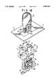
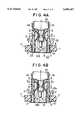
- FIG. 1Ais an exploded perspective view of the assembly of the present invention
- FIG. 1Bis an exploded perspective view of a modified version of the assembly of FIG. 1A;
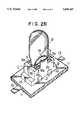
- FIGS. 2A and 2Bare perspective views after assembly of the assembly shown in FIGS. 1A and 1B, respectively;
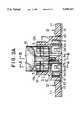
- FIGS. 3A and 3Bare vertical sectional side views of the central portion of the assembly shown in FIGS. 2A and 2B, respectively;
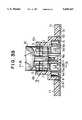
- FIGS. 4A and 4Bare cross-sectional views taken along line A--A of FIGS. 3A and 3B respectively;
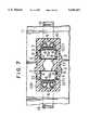
- FIGS. 5, 6 and 7are cross-sectional views taken along lines B--B, C--C and D--D, respectively, of FIG. 3A;
- FIGS. 8 and 9are perspective views showing other examples of connectors of the assembly according to the invention.
- the basic components of the assembly of the present inventionconsist of an insulating holder in which are mounted electrical connectors, the holder being attached to a base.
- the holderincludes a box-shaped holder 1 on which are formed locking tabs 2 and clamping support resilient tabs 1A protruding upwardly as shown in FIG. 1A, said tabs being formed by three-way open and close molding on both the left and right sides of the holder 1, said member 1 being of a heat resistant plastic such as Nylon 66.
- inclined surfaces 2aare formed as shown in FIG. 1 on the upper portions of the two upper locking tabs 2, such inclined surfaces may also be formed on the lower portions of the lower locking tabs 2.
- Projections 4are provided as shown in FIGS. 3A and 4A on one or both of the opposing internal surfaces of the holder 1 between opposing pieces 3 formed to both sides of the member 1 in the direction of the width thereof.
- projections 4are provided as shown in FIGS. 3B and 4B on one or both of the opposing internal surfaces of the holder 1 between opposing pieces 3 formed to both sides of the member 1 in the direction of width thereof, and respectively containing side relief holes 3a on the inside of said sides as shown in FIGS. 1B and 4S.
- the above-mentioned bulb holder 9is engaged as shown in each of the drawings from FIG. 2 to FIG. 7 with base 11 through an engaging hole 10 in said member 11 by utilizing the inclined surfaces 2a of the above-mentioned locking tabs 2, the hole 10 in the base 11 being slightly larger than the outer dimensions of the holder 1 as shown in FIG. 1A.
- connectors 7may he connected to a remote location by means of lead members 6a in the form of lead wires or bus bars as shown in FIGS. 8 and 9, instead of using the plug-in receptacles 6 integrally formed with the base portions of the clamping pieces 5 of the connectors 7.
- FIGS. 1B, 2B, 3B, 4Bare the same as those of FIGS. 1A, 2A, 3A, 4A but with the inclusion therein of side relief holes 3a.
- a known wedge base bulb lamp 12 having a base 12b and provided with conductive lead portions 12a as shown in FIG. 1Ais inserted into bulb holder 9 as shown in FIG. 4A as well as in FIGS. 3A and 5.
- the clamping pieces 5 of connectors 7are pushed apart in opposition to their resiliency by the above-mentioned lead portions 12a of bulb 12, from the broken line position in FIG. 4A to the solid line position.
- a known type of flat fusemay be inserted instead of the abovementioned wedge base bulb 12, while inclined surfaces 2a of locking tabs 2 can be omitted in which case bulb holder 9 can be attached to base 11 through its engaging hole 10 by applying an external force to bend in the sides of the holder 1.
- the present inventionoffers the following advantages.
- the present inventionprovides clamping support resilient tabs 1A, which guard the base of a wedge base bulb or a flat fuse by clamping around it, these tabs 1A being integrally formed with, to protrude from, the upper portion of the holder 1, even when the bulb protrudes significantly from the power supplying base portion thereof, as in the case of wedge base bulbs, the bulb is reliably and stably reinforced whereby it is supported in use.
- Thisoffers a first advantage of safety, in that the lamp or fuse does not come out of the assembly due to external disturbances such as vibrations.
- the holder 1 and the base 11are separate components, the only component that requires the use of an expensive, high-grade and heat resistant plastic is the holder 1. Inexpensive heat-resistant plastic can be used for the base, which uses a much larger amount of plastic than the holder 1. Thus the present invention offers the advantage of less cost than that of the prior art.
- the present inventionprovides U-shaped clamping pieces 5 within the holder 1 extending between opposing upper and lower surfaces of the substantially square-shaped holder 1, and as the periphery of each conductor clamping piece 5 is surrounded by the holder 1, which is an electrically insulating member, there can be no inadvertent contact by external conductors (such as a screwdriver or other tool) with the clamping pieces 5 or with electrically conducting portions of the lamp clamped in the conductors 7 during automobile repair or inspection.
- external conductorssuch as a screwdriver or other tool
Landscapes
- Connecting Device With Holders (AREA)
- Connector Housings Or Holding Contact Members (AREA)
- Fastening Of Light Sources Or Lamp Holders (AREA)
Abstract
Description
Claims (5)
Applications Claiming Priority (4)
| Application Number | Priority Date | Filing Date | Title |
|---|---|---|---|
| JP6-262107 | 1994-09-30 | ||
| JP6262107AJP3000192B2 (en) | 1994-09-30 | 1994-09-30 | Socket for wedge base valve |
| JP6-266350 | 1994-10-05 | ||
| JP6266350AJPH08106966A (en) | 1994-10-05 | 1994-10-05 | Installing constituent body of connecting tool |
Publications (1)
| Publication Number | Publication Date |
|---|---|
| US5695367Atrue US5695367A (en) | 1997-12-09 |
Family
ID=26545391
Family Applications (1)
| Application Number | Title | Priority Date | Filing Date |
|---|---|---|---|
| US08/520,782Expired - Fee RelatedUS5695367A (en) | 1994-09-30 | 1995-08-29 | Connector attachment component |
Country Status (6)
| Country | Link |
|---|---|
| US (1) | US5695367A (en) |
| KR (1) | KR0159151B1 (en) |
| CN (1) | CN1091965C (en) |
| CA (1) | CA2157952C (en) |
| DE (1) | DE19536455C2 (en) |
| GB (1) | GB2293701B (en) |
Cited By (12)
| Publication number | Priority date | Publication date | Assignee | Title |
|---|---|---|---|---|
| US5876251A (en)* | 1996-07-04 | 1999-03-02 | Sumitomo Wiring Systems, Ltd. | L-shaped bulb connector |
| EP0944140A1 (en)* | 1998-03-19 | 1999-09-22 | The Whitaker Corporation | Electrical connector for leaded electronic component |
| EP1045492A3 (en)* | 1999-04-14 | 2001-09-12 | BENDER & WIRTH GMBH & CO. | Socket for multi-pin lamps |
| EP1045198A3 (en)* | 1999-04-16 | 2002-04-24 | BJB GmbH & Co. KG | Socket for halogen bulb |
| US20040132336A1 (en)* | 2001-10-04 | 2004-07-08 | Guide Corporation | Terminal alignment features for bulb sockets |
| EP1289070A3 (en)* | 2001-08-31 | 2004-08-11 | Fci | Power connector |
| US20050258764A1 (en)* | 2004-05-21 | 2005-11-24 | Yazaki Corporation | Vehicle interior illumination lamp |
| US6971917B2 (en) | 2003-02-12 | 2005-12-06 | Vossloh-Schwabe Deutschland Gmbh | Socket for an electrically operated device |
| US20080273343A1 (en)* | 2007-05-04 | 2008-11-06 | Runions Alton E | Halogen burner and receptacle assembly |
| US20150118879A1 (en)* | 2012-08-27 | 2015-04-30 | Ideal Industries, Inc. | Methods and apparatus for grounding an electrical device via a lampholder |
| CN113661606A (en)* | 2019-08-27 | 2021-11-16 | 株式会社Lg新能源 | Connectors, Battery Management Units and Battery Packs |
| US20230276587A1 (en)* | 2020-07-31 | 2023-08-31 | Lg Innotek Co., Ltd. | Power module |
Families Citing this family (3)
| Publication number | Priority date | Publication date | Assignee | Title |
|---|---|---|---|---|
| DE10226489B4 (en)* | 2002-06-14 | 2004-10-28 | Wieland Electric Gmbh | terminal connector |
| US7025634B1 (en)* | 2005-05-16 | 2006-04-11 | Osram Sylvania Inc. | Lamp socket |
| CN102306618B (en)* | 2011-09-09 | 2014-03-19 | 宁波卓明电子有限公司 | Halogen bulb |
Citations (10)
| Publication number | Priority date | Publication date | Assignee | Title |
|---|---|---|---|---|
| US4418973A (en)* | 1981-09-04 | 1983-12-06 | General Electric Company | Wedge base lamp socket assembly |
| DE4022876A1 (en)* | 1989-07-21 | 1991-01-31 | Daiichi Denso Buhin | CONNECTING FASTENING DEVICE |
| US5035643A (en)* | 1989-05-17 | 1991-07-30 | Zanxx, Inc. | Axial low profile lamp socket assembly |
| DE4113559A1 (en)* | 1990-04-25 | 1991-10-31 | Daiichi Denso Buhin | CONNECTOR MOUNTING ARRANGEMENT |
| US5078625A (en)* | 1989-06-20 | 1992-01-07 | Stanley Electric Co., Ltd. | Wedge base socket attached to spg substrate |
| JPH045082U (en)* | 1990-04-25 | 1992-01-17 | ||
| GB2270804A (en)* | 1992-09-02 | 1994-03-23 | Daiichi Denso Buhin | Connector for electrical components |
| GB2279186A (en)* | 1993-06-16 | 1994-12-21 | Daiichi Denso Buhin | An electrical connector assembly |
| GB2287141A (en)* | 1994-03-02 | 1995-09-06 | Daiichi Denso Buhin | An electrical connector assembly |
| US5597329A (en)* | 1993-11-15 | 1997-01-28 | Daiichi Denso Buhin Co., Ltd. | Connector attachment component |
Family Cites Families (1)
| Publication number | Priority date | Publication date | Assignee | Title |
|---|---|---|---|---|
| US5035645A (en)* | 1988-01-15 | 1991-07-30 | The Siemon Company | Bracket for terminal block |
- 1995
- 1995-08-29USUS08/520,782patent/US5695367A/ennot_activeExpired - Fee Related
- 1995-09-11CACA002157952Apatent/CA2157952C/ennot_activeExpired - Fee Related
- 1995-09-26GBGB9519629Apatent/GB2293701B/ennot_activeExpired - Fee Related
- 1995-09-27KRKR1019950032006Apatent/KR0159151B1/ennot_activeExpired - Fee Related
- 1995-09-29DEDE19536455Apatent/DE19536455C2/ennot_activeExpired - Fee Related
- 1995-09-29CNCN95119114Apatent/CN1091965C/ennot_activeExpired - Fee Related
Patent Citations (13)
| Publication number | Priority date | Publication date | Assignee | Title |
|---|---|---|---|---|
| US4418973A (en)* | 1981-09-04 | 1983-12-06 | General Electric Company | Wedge base lamp socket assembly |
| US5035643A (en)* | 1989-05-17 | 1991-07-30 | Zanxx, Inc. | Axial low profile lamp socket assembly |
| US5078625A (en)* | 1989-06-20 | 1992-01-07 | Stanley Electric Co., Ltd. | Wedge base socket attached to spg substrate |
| GB2235832A (en)* | 1989-07-21 | 1991-03-13 | Daiichi Denso Buhin | Mounting a fuseholder. |
| DE4022876A1 (en)* | 1989-07-21 | 1991-01-31 | Daiichi Denso Buhin | CONNECTING FASTENING DEVICE |
| DE4113559A1 (en)* | 1990-04-25 | 1991-10-31 | Daiichi Denso Buhin | CONNECTOR MOUNTING ARRANGEMENT |
| GB2244391A (en)* | 1990-04-25 | 1991-11-27 | Daiichi Denso Buhin | Connector device |
| JPH045082U (en)* | 1990-04-25 | 1992-01-17 | ||
| GB2270804A (en)* | 1992-09-02 | 1994-03-23 | Daiichi Denso Buhin | Connector for electrical components |
| GB2279186A (en)* | 1993-06-16 | 1994-12-21 | Daiichi Denso Buhin | An electrical connector assembly |
| US5597329A (en)* | 1993-11-15 | 1997-01-28 | Daiichi Denso Buhin Co., Ltd. | Connector attachment component |
| GB2287141A (en)* | 1994-03-02 | 1995-09-06 | Daiichi Denso Buhin | An electrical connector assembly |
| US5558543A (en)* | 1994-03-02 | 1996-09-24 | Daiichi, Denso Buhin Co., Ltd. | Connector attachment component |
Cited By (22)
| Publication number | Priority date | Publication date | Assignee | Title |
|---|---|---|---|---|
| US5876251A (en)* | 1996-07-04 | 1999-03-02 | Sumitomo Wiring Systems, Ltd. | L-shaped bulb connector |
| EP0944140A1 (en)* | 1998-03-19 | 1999-09-22 | The Whitaker Corporation | Electrical connector for leaded electronic component |
| US6231370B1 (en) | 1998-03-19 | 2001-05-15 | The Whitaker Corporation | Electrical connector for leaded electronic component |
| EP1045492A3 (en)* | 1999-04-14 | 2001-09-12 | BENDER & WIRTH GMBH & CO. | Socket for multi-pin lamps |
| EP1045198A3 (en)* | 1999-04-16 | 2002-04-24 | BJB GmbH & Co. KG | Socket for halogen bulb |
| CN100429834C (en)* | 2001-08-31 | 2008-10-29 | Fci公司 | power connector |
| EP1289070A3 (en)* | 2001-08-31 | 2004-08-11 | Fci | Power connector |
| US20060189217A1 (en)* | 2001-10-04 | 2006-08-24 | Guide Corporation | Terminals for bulb sockets |
| US7063575B2 (en) | 2001-10-04 | 2006-06-20 | Guide Corporation | Terminal alignment features for bulb sockets |
| US7192315B2 (en) | 2001-10-04 | 2007-03-20 | Guide Corporation | Terminals for bulb sockets |
| US20040132336A1 (en)* | 2001-10-04 | 2004-07-08 | Guide Corporation | Terminal alignment features for bulb sockets |
| US6971917B2 (en) | 2003-02-12 | 2005-12-06 | Vossloh-Schwabe Deutschland Gmbh | Socket for an electrically operated device |
| US20050258764A1 (en)* | 2004-05-21 | 2005-11-24 | Yazaki Corporation | Vehicle interior illumination lamp |
| US7207847B2 (en)* | 2004-05-21 | 2007-04-24 | Yazaki Corporation | Vehicle interior illumination lamp |
| US20080273343A1 (en)* | 2007-05-04 | 2008-11-06 | Runions Alton E | Halogen burner and receptacle assembly |
| US7494262B2 (en)* | 2007-05-04 | 2009-02-24 | Honeywell International Inc. | Halogen burner and receptacle assembly |
| US20150118879A1 (en)* | 2012-08-27 | 2015-04-30 | Ideal Industries, Inc. | Methods and apparatus for grounding an electrical device via a lampholder |
| US9391415B2 (en)* | 2012-08-27 | 2016-07-12 | Ideal Industries, Inc. | Methods and apparatus for grounding an electrical device via a lampholder |
| CN113661606A (en)* | 2019-08-27 | 2021-11-16 | 株式会社Lg新能源 | Connectors, Battery Management Units and Battery Packs |
| US12051868B2 (en) | 2019-08-27 | 2024-07-30 | Lg Energy Solution, Ltd. | Connector, battery management unit and battery pack |
| US20230276587A1 (en)* | 2020-07-31 | 2023-08-31 | Lg Innotek Co., Ltd. | Power module |
| US12245388B2 (en)* | 2020-07-31 | 2025-03-04 | Lg Innotek Co., Ltd. | Power module |
Also Published As
| Publication number | Publication date |
|---|---|
| GB2293701A (en) | 1996-04-03 |
| HK1000269A1 (en) | 1998-02-13 |
| GB9519629D0 (en) | 1995-11-29 |
| KR0159151B1 (en) | 1999-02-18 |
| DE19536455A1 (en) | 1996-04-04 |
| DE19536455C2 (en) | 2001-04-26 |
| CN1091965C (en) | 2002-10-02 |
| CN1135669A (en) | 1996-11-13 |
| CA2157952C (en) | 2000-01-11 |
| GB2293701B (en) | 1996-11-20 |
| KR960012630A (en) | 1996-04-20 |
| CA2157952A1 (en) | 1996-03-31 |
Similar Documents
| Publication | Publication Date | Title |
|---|---|---|
| US5695367A (en) | Connector attachment component | |
| CA2006170C (en) | Clamp type connection device | |
| US5049092A (en) | Connector assembly for electrical components | |
| US5558543A (en) | Connector attachment component | |
| US5108314A (en) | Connector assembly for electrical components | |
| US5597329A (en) | Connector attachment component | |
| CA2125798C (en) | Connector attachment component | |
| US5389010A (en) | Connector for electrical components | |
| KR100289215B1 (en) | Switch connection structure | |
| KR100289217B1 (en) | switch | |
| EP2345840B1 (en) | Connector terminal for lamps | |
| EP0707325B1 (en) | Improved fuse holder assembly having improved fuse clips for mounting on a printed circuit board | |
| KR20030030898A (en) | Lamp socket as well as assembly consisting of a lamp socket and a reflector | |
| US3887258A (en) | Wire connector means for vehicle lamp | |
| JP3000192B2 (en) | Socket for wedge base valve | |
| JPH08106966A (en) | Installing constituent body of connecting tool | |
| JPH0719106Y2 (en) | Attachment mounting structure | |
| JPH0644047Y2 (en) | Attachment mounting structure | |
| JPH0648775Y2 (en) | Lamp mounting structure | |
| JPH0719105Y2 (en) | Attachment mounting structure | |
| JP2506850Y2 (en) | Attachment mounting structure | |
| JPH0633670Y2 (en) | Attachment mounting structure | |
| JPH07226274A (en) | Installing structural body of connector |
Legal Events
| Date | Code | Title | Description |
|---|---|---|---|
| AS | Assignment | Owner name:DALICHI DENSO BUHIN CO., LTD., JAPAN Free format text:ASSIGNMENT OF ASSIGNORS INTEREST;ASSIGNORS:TAKANO, TSUNESUKE;SINZAWA, KOUICHI;REEL/FRAME:008051/0164 Effective date:19950905 | |
| FPAY | Fee payment | Year of fee payment:4 | |
| AS | Assignment | Owner name:DAIICHI DENSO BUHLIN CO., LTD., JAPAN Free format text:CORPORATE REGISTER ADDRESS CHANGE;ASSIGNOR:DENSO BUHIN CO., LTD.;REEL/FRAME:012447/0924 Effective date:20010809 Owner name:DAIICHI DENSO BUHLIN CO., LTD., JAPAN Free format text:INVALID ASSIGNMENT;ASSIGNOR:DENSO BUHIN CO., LTD.;REEL/FRAME:012729/0940 Effective date:20010809 Owner name:DAIICHI DENSO BUHIN CO., LTD., JAPAN Free format text:CHANGE OF ADDRESS;ASSIGNOR:DAIICHI DENSO BUHIN CO., LTD.;REEL/FRAME:012822/0297 Effective date:20010809 | |
| FPAY | Fee payment | Year of fee payment:8 | |
| REMI | Maintenance fee reminder mailed | ||
| LAPS | Lapse for failure to pay maintenance fees | ||
| STCH | Information on status: patent discontinuation | Free format text:PATENT EXPIRED DUE TO NONPAYMENT OF MAINTENANCE FEES UNDER 37 CFR 1.362 | |
| FP | Lapsed due to failure to pay maintenance fee | Effective date:20091209 |