US5694268A - Spindle motor having overmolded stator - Google Patents
Spindle motor having overmolded statorDownload PDFInfo
- Publication number
- US5694268A US5694268AUS08/550,175US55017595AUS5694268AUS 5694268 AUS5694268 AUS 5694268AUS 55017595 AUS55017595 AUS 55017595AUS 5694268 AUS5694268 AUS 5694268A
- Authority
- US
- United States
- Prior art keywords
- stator
- base
- disc drive
- spindle motor
- overmold
- Prior art date
- Legal status (The legal status is an assumption and is not a legal conclusion. Google has not performed a legal analysis and makes no representation as to the accuracy of the status listed.)
- Expired - Lifetime
Links
Images


Classifications
- G—PHYSICS
- G11—INFORMATION STORAGE
- G11B—INFORMATION STORAGE BASED ON RELATIVE MOVEMENT BETWEEN RECORD CARRIER AND TRANSDUCER
- G11B19/00—Driving, starting, stopping record carriers not specifically of filamentary or web form, or of supports therefor; Control thereof; Control of operating function ; Driving both disc and head
- G11B19/20—Driving; Starting; Stopping; Control thereof
- G11B19/2009—Turntables, hubs and motors for disk drives; Mounting of motors in the drive
- G11B19/2018—Incorporating means for passive damping of vibration, either in the turntable, motor or mounting
- H—ELECTRICITY
- H02—GENERATION; CONVERSION OR DISTRIBUTION OF ELECTRIC POWER
- H02K—DYNAMO-ELECTRIC MACHINES
- H02K1/00—Details of the magnetic circuit
- H02K1/06—Details of the magnetic circuit characterised by the shape, form or construction
- H02K1/12—Stationary parts of the magnetic circuit
- H02K1/18—Means for mounting or fastening magnetic stationary parts on to, or to, the stator structures
- H02K1/185—Means for mounting or fastening magnetic stationary parts on to, or to, the stator structures to outer stators
- H—ELECTRICITY
- H02—GENERATION; CONVERSION OR DISTRIBUTION OF ELECTRIC POWER
- H02K—DYNAMO-ELECTRIC MACHINES
- H02K1/00—Details of the magnetic circuit
- H02K1/06—Details of the magnetic circuit characterised by the shape, form or construction
- H02K1/12—Stationary parts of the magnetic circuit
- H02K1/18—Means for mounting or fastening magnetic stationary parts on to, or to, the stator structures
- H02K1/187—Means for mounting or fastening magnetic stationary parts on to, or to, the stator structures to inner stators
- G—PHYSICS
- G11—INFORMATION STORAGE
- G11B—INFORMATION STORAGE BASED ON RELATIVE MOVEMENT BETWEEN RECORD CARRIER AND TRANSDUCER
- G11B25/00—Apparatus characterised by the shape of record carrier employed but not specific to the method of recording or reproducing, e.g. dictating apparatus; Combinations of such apparatus
- G11B25/04—Apparatus characterised by the shape of record carrier employed but not specific to the method of recording or reproducing, e.g. dictating apparatus; Combinations of such apparatus using flat record carriers, e.g. disc, card
- G11B25/043—Apparatus characterised by the shape of record carrier employed but not specific to the method of recording or reproducing, e.g. dictating apparatus; Combinations of such apparatus using flat record carriers, e.g. disc, card using rotating discs
Definitions
- the present inventionrelates generally to the field of disc drive spindle motors for data storage devices and, more particularly, to a spindle motor in which the stator has a resilient overmold to isolate the stator from a base of the storage device.
- Winchester type disc drivesare well-known in the industry.
- digital dataare written to and read from a thin layer of magnetizable material on the surface of rotating discs.
- Write and read operationsare performed through a transducer which is carried in a slider body.
- the slider and transducerare sometimes collectively referred to as a head, and typically a single head is associated with each disc surface.
- the headsare selectively moved under the control of electronic circuitry to any one of a plurality of circular, concentric data tracks on the disc surface by an actuator device.
- Each slider bodyincludes a self-acting hydrodynamic air bearing surface. As the disc rotates, the disc drags air beneath the air bearing surface, which develops a lifting force that causes the slider to lift and fly several microinches above the disc surface.
- the most commonly used type of actuatoris a rotary moving coil actuator.
- the discsthemselves are typically mounted in a "stack" on the hub structure of a brushless DC spindle motor.
- the rotational speed of the spindle motoris precisely controlled by motor drive circuitry which controls both the timing and the power of commutation signals directed to the stator windings of the motor.
- the first Winchester disc drives to be producedwere large cabinet models which included discs having a diameter of 14 inches and AC induction spindle motors. These types of disc drives were commonly located in dedicated "computer rooms” with large mainframe computers, where environmental factors such as temperature and humidity could be carefully controlled. In this type of environment, the acoustic noise generated by cooling fans and disc drive motors was of little concern, since the only persons directly in contact with the systems were maintenance personnel, who were generally not in the computer rooms for extended periods of time. The users of such systems were typically located at a remote location and communicated with the computer system via keyboards and display terminals which did not generate excessive amounts of acoustic noise.
- spindle motorwhich drives the discs at a constant speed.
- Typical spindle motor speedshave been in the range of 3600 RPM.
- Current technologyhas increased spindle motor speeds to 4800 RPM, 7200 RPM and above.
- Analysis of various types of disc driveshas brought to light several different modes of acoustic noise generation which are attributable to the spindle motor and its control logic.
- One mode of noise generationis sympathetic vibration of the disc drive housing in response to the rotating mass of the spindle motor.
- Another mode of acoustic noise generationis electromagnetic disturbances caused by the excitation of the stator mass by the application and removal of the commutation pulses that are used to drive the motor and control its speed.
- the commutation pulsesare timed, polarization-selected DC current pulses which are directed to sequentially selected stator windings. The rapid rise and fall times of these pulses act as a striking force and set up sympathetic vibrations in the stator structure.
- stator structureis rigidly connected to the disc drive housing, either directly or through a rigid material, these vibrations are coupled to the housing and generate resonant vibrations in the housing causing unacceptable levels of acoustic noise.
- Prior art attempts to reduce or eliminate noiseinclude controlling the resonant frequency of the housing, and damping the vibration of the housing.
- acoustic noiseis reduced by uncoupling the stator from hard contact with the stationary portion of the shaft.
- a plurality of O-ringsinterposed radially between the stator and the shaft of the spindle motor.
- a non-metallic washeris positioned at one end of the shaft and an axial O-ring is positioned at the other end of the shaft.
- the present inventionis a disc drive spindle motor for rotating at least one disc in a data storage device.
- the motorincludes a base, a stationary member, a rotor and a stator.
- a bearinginterconnects the rotor with the stationary member and allows the rotor to rotate about the stationary member.
- An overmoldencapsulates at least part of the stator and provides the stator with a smooth external surface. The overmold mechanically isolates the stator from the base and damps sympathetic vibrations in the stator structure to reduce the generation of acoustic noise in the storage device.
- the overmoldprovides a convenient structure for mounting the stator to the base.
- the statorincludes a plurality of phase windings which are disposed about the stator and spaced apart by gaps.
- the overmoldfills the gaps and substantially encapsulates the stator.
- a plurality of mounting aperturesextend in an axial direction through the overmold in the gaps between the phase windings.
- a mounting pinextends through each mounting aperture and has a distal end which can be attached to the base by heat-staking, for example.
- the overmoldcomprises at a plurality of mounting ears extending from a circumference of the stator in a radial direction for connection to the base.
- the mounting earscan include a rigid material, such as plastic or metal, which is encapsulated by the overmold or exposed to provide a rigid yet isolated connection.
- the overmoldhas a circumferential side wall opposite to the rotor having an annular raised projection.
- the projectionis compressed between the stator and the base to secure the stator within the base.
- the statoris adhered to the base through a polyester plastic film having first and second surfaces which carry a pressure sensitive adhesive.
- the overmolded statorcan have an axial position which is within or below the hub, and can have a radial position which is internal or external to the rotor.
- the overmoldprovides the stator with an environmental seal having a smooth external surface which is substantially free of apertures. The overmold can be cleaned more easily during production than a bare stator and therefore reduces impurities in the disc drive.
- the overmoldprovides a large surface area over which vibrations can be damped to reduce acoustic noise generation.
- the overmoldalso allows a greater integration of parts which reduces the number of parts that must be assembled in the disc drive.
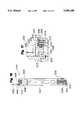
- FIG. 1is a top plan view of a disc drive data storage device, in accordance with the present invention.
- FIG. 2is a sectional view of an isolated hydrodynamic bearing spindle motor in accordance with the present invention.
- FIG. 3is a fragmentary sectional view of an alternative attachment between the stator and the base in which the stator is partially isolated from the disc.
- FIG. 4is a fragmentary sectional view of an alternative attachment between the stator and the base which includes two O-rings for isolation.
- FIG. 5is a fragmentary sectional view of another alternative attachment between the stator and the base which includes an O-ring located radially between the stator and the base and an O-ring located axially between the stator and the base.
- FIG. 6is a sectional view of a ball bearing spindle motor, in accordance with the present invention.
- FIG. 7is a plan view of an overmolded stator in accordance with the present invention.
- FIG. 8is a sectional view of the stator shown in FIG. 7, taken along lines 7--7.
- FIG. 9is a fragmentary sectional view of a spindle motor having the stator shown in FIGS. 7 and 8.
- FIG. 10is a sectional view of a fully encapsulated stator.
- FIG. 11is a sectional view of a overmolded stator having flux shields.
- FIG. 12is a plan view of an overmolded stator having mounting ears.
- FIG. 13is a sectional view of the stator shown in FIG. 12, taken along line 13--13.
- FIG. 14is a fragmentary sectional view of a spindle motor having the stator shown in FIGS. 12 and 13.
- FIG. 15is a plan view of a overmolded stator having a rigid mounting ring formed within the overmolding.
- FIG. 16is a sectional view of the stator shown in FIG. 15, taken along lines 16--16.
- FIG. 17is a fragmentary sectional view of a spindle motor having the stator shown in FIGS. 15 and 16.
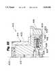
- FIG. 18is a sectional view of an overmolded stator with an annular projection.
- FIG. 19is a fragmentary sectional view of a spindle motor having the stator shown in FIG. 18.
- FIG. 20is a fragmentary sectional view of a spindle motor in which an overmolded stator is adhered to the base through a polyester plastic film.
- FIG. 21is a sectional view of an overmolded stator in which the overmold is limited to an outer diameter of the stator.
- FIG. 22is a fragmentary sectional view of a spindle motor having an overmolded stator with a radial position that is internal to the rotor.
- FIG. 1is a plan view of a typical disc drive 10 in which the present invention is useful.
- Disc drive 10includes a housing base 12 and a top cover 14. The housing base 12 is combined with top cover 14 to form a sealed environment to protect the internal components from contamination by elements from outside the sealed environment.
- the base and top cover arrangement shown in FIG. 1is common in the industry. However, other arrangements of the housing components have been frequently used, and the present invention is not limited to the configuration of the disc drive housing.
- disc driveshave been manufactured using a vertical split between two housing members. In such drives, that portion of the housing half which connects to the lower end of the spindle motor is analogous to base 12, while the opposite side of the same housing member, which is connected to or adjacent the top of the spindle motor, is functionally the same as the top cover 14.
- Disc drive 10further includes a disc pack 16 which is mounted for rotation on a spindle motor (not shown) by a disc clamp 18.
- Disc pack 16includes a plurality of individual discs which are mounted for co-rotation about a central axis. Each disc surface has an associated head 20 which is mounted to disc drive 10 for communicating with the disc surface.
- heads 20are supported by flexures 22 which are in turn attached to head mounting arms 24 of an actuator body 26.
- the actuator shown in FIG. 1is of the type known as a rotary moving coil actuator and includes a voice coil motor (VCM), shown generally at 28.
- Voice coil motor 28rotates actuator body 26 with its attached heads 20 about a pivot shaft 30 to position heads 20 over a desired data track along an arcuate path 32. While a rotary actuator is shown in FIG. 1, the present invention is also useful in disc drives having other types of actuators, such as linear actuators.
- FIG. 2is a sectional view of a hydrodynamic bearing spindle motor 32 in accordance with the present invention.
- Spindle motor 32includes a stationary member 34, a hub or sleeve 36 and a stator 38.
- the stationary memberis a shaft which is fixed and attached to base 12 through a nut 40 and a washer 42.
- Hub 36is interconnected with shaft 34 through a hydrodynamic bearing 37 for rotation about shaft 34.
- Bearing 37includes a radial working surface 46 and axial working surfaces 48 and 50.
- Shaft 34includes fluid ports 54, 56 and 58 which supply hydrodynamic fluid 60 and assist in circulating the fluid along the working surfaces of the bearing.
- Hydrodynamic fluid 60is supplied to shaft 34 by a fluid source (not shown) which is coupled to the interior of shaft 34 in a known manner.
- Spindle motor 32further includes a thrust bearing 45 which forms the axial working surfaces 48 and 50 of hydrodynamic bearing 37.
- a counterplate 62bears against working surface 48 to provide axial stability for the hydrodynamic bearing and to position hub 36 within spindle motor 32.
- An O-ring 64is provided between counterplate 62 and hub 36 to seal the hydrodynamic bearing. The seal prevents hydrodynamic fluid 60 from escaping between counterplate 62 and hub 36.
- Hub 36includes a disc carrier member 66 which supports disc pack 16 (shown in FIG. 1) for rotation about shaft 34.
- Disc pack 16is held on disc carrier member 66 by disc clamp 18 (also shown in FIG. 1).
- a permanent magnet 70is attached to the outer diameter of hub 36, which acts as a rotor for spindle motor 32.
- Stator 38is formed of a stack of stator laminations 72 and associated stator windings 74.
- stator 38is mechanically isolated from base 12 through a resilient coupling. It has been found through experiments that hydrodynamic bearing motors are much quieter and in general have lower background vibration levels than motors having ball bearings. Because the background vibration levels are less in a hydrodynamic bearing motor, vibration responses to electromagnetic disturbances become more noticeable since the responses are no longer hidden in the background. Therefore, it is desirable to reduce or eliminate as far as possible the transfer of vibrations resulting from electromagnetic disturbances from the stator to the base.
- stator 38is resiliently coupled to, but mechanically isolated from, base 12.
- Stator 38is coupled to base 12 through an O-ring 80 and a resilient damping bridge 82.
- O-ring 80is compressed between a side surface 84 of stator 38 and a side surface 86 of base 12 such that stator 38 and base 12 are adjacent to, but spaced from, one another in a radial direction with respect to a central axis 87.
- O-ring 80is integrated in stator 38 to form an assembly which facilitates a low-cost approach to mounting the stator within base 12.
- O-ring 80can be integrated in an indentation (not shown) in stator 38 through a vulcanizing process.
- O-ring 80can also be integrated in stator 38 by over-molding the O-ring onto the stator.
- the O-ring materialflows over the stator to form the desired O-ring features and is then hardened at a selected temperature and pressure.
- the vulcanizing process and the over-molding processare controlled to provide the desired damping and stiffness characteristics.
- Base 12includes a corresponding annular groove (not labeled) which retains O-ring 80 under compression when stator 38 is mounted within base 12.
- the annular groove within base 12also assists in axially constraining O-ring 80.
- O-ring 80can be formed as a continuous internal ring or as one or more individual pieces of O-ring material positioned between stator 38 and base 12.
- O-ring 80can have any suitable cross section, such as circular or rectangular.
- O-ring 80can be formed of a rubber-like or plastic-like material having high stiffness and high vibration damping characteristics.
- O-ring 80is formed of an approximately 40-75 durometer (Shore A) material having a damping ratio of at least 2 decibels in an acoustic frequency range of approximately 100 Hz to 10 KHz. The material absorbs energy of acoustic vibrations and dissipates the energy as heat.
- O-ring 80preferably has a damping ratio of at least 5 decibels. The preferred damping ratio depends on the type of bearing used, among other factors. With ball bearings, the background vibration level is higher. Electromagnetic disturbances are more hidden and require less damping. A damping ratio of 2-3 decibels may be sufficient. With hydrodynamic bearings, electromagnetic disturbances are more noticeable. A larger damping ratio is therefore preferred with hydrodynamic bearings.
- a suitable materialis a 70 durometer material such as Viton®, a patented polymer product of E.I. DuPont de Nemours Co., of Wilmington, Del., which is subjected to 0.009 inches of radial compression.
- Viton®a patented polymer product of E.I. DuPont de Nemours Co., of Wilmington, Del.
- Other materials which provide suitable isolation and stiffnessmay also be used to isolate stator 38 from base 12. It has been found that some rubber materials contain silicone or sulfur which can be harmful to the various components in a disc drive. Therefore, rubber or rubber-like materials not containing silicone and sulfur are preferred.
- Resilient bridge 82extends between an upper mounting surface 90 of stator 38 and an upper mounting surface 92 of base 12. Bolts 94 and 96 secure bridge 82 to base 12 and compress bridge 82 against the upper mounting surfaces 90 and 92 in an axial direction to provide additional vertical stiffness for the resilient coupling between stator 38 and base 12.
- the combination of O-ring 80 and resilient bridge 82clamps stator 38 rotationally and vertically with respect to base 12.
- the O-ringpreferably has enough torsional stiffness so that as spindle motor 32 begins to rotate, stator 38 is not allowed to rotate more than an insignificant amount.
- the combination of O-ring 80 and resilient bridge 82provides sufficient vertical and torsional stiffness.
- Resilient bridge 82is preferably formed of a material similar to that of O-ring 80.
- Resilient bridge 82can be an annular ring, as shown in FIG. 2, or can include one or more individual bridge pieces which extend between stator 38 and base 12.
- bridge 82can be formed as a washer which is secured to base 12 by a bolt, such as bolt 94 or 96. The washer would have a tab that would extend between base 12 and stator 38.
- Resilient bridge 82can also be formed as a clamp of O-ring type material.
- bridge 82can be compressed against the upper mounting surfaces 90 and 92 in several ways.
- resilient bridge 82can be compressed by bolt 94, as shown in FIG. 2, or can be compressed by a portion of top cover 14 (shown in FIG. 1).
- the mounting surfaces 90 and 92can also include associated grooves for accepting resilient bridge 82.
- resilient bridge 82can be integrated into the stator similar to O-ring 80.
- the spindle motoris a "below-hub” type motor in which stator 38 is positioned below hub 36, as opposed to within hub 36.
- stator 38is located externally from hub 36 and is attached directly to base 12.
- O-ring 80 and resilient damping bridge 82are located at an outer diameter of stator 38.
- FIG. 3is a fragmentary sectional view of a spindle motor which illustrates an alternative attachment between the stator and the base.
- stator 100is attached to base 102 through an O-ring 104 and a metallic C-clamp 106.
- C-clamp 106provides sufficient vertical stiffness between stator 100 and base 102 but does not provide complete isolation between the stator and the base as does the embodiment shown in FIG. 2. Therefore, the embodiment shown in FIG. 2 is preferred over the embodiment shown in FIG. 3.
- FIG. 4is a fragmentary sectional view of a spindle motor illustrating another alternative attachment between the stator and the base.
- stator 110is attached to base 112 through two O-rings 114 and 116.
- O-rings 114 and 116are located radially between stator 110 and 112.
- O-rings 114 and 116are separated from one another by a radius such that they form a couple which contributes to the vertical and torsional stiffness of stator 110 with respect to base 112. If the stator is rotated with respect to the base, the O-rings provide a restoring torque to overcome the rotation.
- the O-ringsalso maintain vertical alignment of the stator by providing a restoring force in a vertical direction in response to vertical movement of the stator with respect to the base.
- FIG. 5is a fragmentary sectional view of a spindle motor which illustrates another embodiment of the present invention.
- stator 120is resiliently coupled to base 122 through O-rings 124 and 126.
- O-ring 124is located radially between stator 120 and base 122.
- O-ring 124is compressed between the side walls of stator 120 and base 122 similar to the O-rings shown in FIGS. 2-4.
- O-ring 126is located axially and compressed between a lower mounting surface 128 of stator 120 and an opposing surface 130 of base 122.
- O-ring 126provides additional stability and isolation. rectangular.
- While the present inventionis particularly useful in hydrodynamic bearing motors to reduce pure tone vibrations where the background vibration level is relatively low, the present invention is also useful in motors having ball bearings to reduce or eliminate the transfer of vibrations from the stator to the base.
- FIG. 6illustrates a spindle motor having ball bearings, as opposed to a hydrodynamic bearing.
- Spindle motor 150includes a shaft 152, a hub 154 and a stator 156.
- Shaft 152is a stationary shaft which is fixedly attached to a base 158.
- Shaft 152is also attached to the inner races of ball bearings 160 and 162.
- Hub 154is attached to the outer races of bearings 160 and 162 for rotation about shaft 152.
- Hub 154includes a disc carrying member 164 which carries a plurality of magnetic discs (not shown) for rotation about shaft 152.
- Hub 154also carries a permanent magnet 166 which forms a rotor for spindle motor 150.
- stator 156can be attached to base 158 through one or more resilient couplings, such as O-ring 168.
- Spindle motor 150can also include a resilient damping ring or tab 170 for providing additional vertical stiffness between stator 156 and base 158. As discussed above, damping ring or tab 170 is optional.
- spindle motor 150can be provided with a metallic C-clamp as shown in FIG. 3, two O-rings as shown in FIG. 4, or an additional O-ring located between the bottom of stator 156 and base 158.
- FIGS. 1-6illustrate embodiments in which the stator is positioned external to the hub such that the O-rings are positioned along the outer diameter of the stator.
- the O-ringscan also be positioned along the inner diameter of the stator in embodiments in which the stator is attached to the base about the stator's inner diameter.
- FIG. 7is a plan view of a stator in which the resilient coupling is integrated with the stator by overmolding the coupling onto the stator.
- FIG. 8is a sectional view of the stator, taken along lines 8--8 of FIG. 7.
- Stator 200includes a stator lamination 202 comprising a back-iron 204 and a plurality of teeth 206a-206l, which extend inward from back-iron 204 toward a central axis 207. Teeth 206a-206l are disposed about a circumference 222 of stator 200.
- a plurality of phase windings 208a-208lare wound on stator teeth 206a-206l, respectively, for magnetic communication with an internal rotor (not shown).
- Phase windings 208a-208lcan have a number of winding configurations, such as those discussed in Dunfield et al. U.S. Ser. No. 08/469,643, entitled IRONLESS HYDRODYNAMIC SPINDLE MOTOR, filed Jun. 6, 1995, and Dunfield et al. U.S. Ser. No. 08/400,661, entitled HYDRODYNAMIC SPINDLE MOTOR HAVING DISTRIBUTED WINDINGS, filed Mar. 8, 1995, which are hereby incorporated by reference.
- a flexible printed circuit (FPC 210carries a plurality of conductors 212 which are electrically connected to start and finish winding terminations 214, 216,218 and 220. Terminations 214,216, and 218 and 220 are electrically connected to phase windings 208a-208l, in a known manner.
- stator teeth 206a-206l and windings 208a-208lare overmolded by a resilient rubber-like or plastic-like material. Gaps 224a-224l are formed between each phase winding 208a-208l.
- Overmold 209substantially encapsulates stator 200 and fills gaps 224a-224l such that stator 200 has a smooth external surface which is substantially free of apertures, indentations or open cavities. This provides an environmental seal and a surface which can be cleaned much more easily during assembly than a rough and uneven surface provided by an exposed stator.
- Each of the stator lamination teeth 206a-206lremain exposed at an inner diameter surface 236 along circumference 222 for closer communication with the rotor.
- overmold 209has a minimum thickness of approximately 0.25 mm around the various features of stator 200.
- the overmold materialincludes a 70 durometer rubber-like material having characteristics similar to the O-rings discussed with reference to FIG. 2. Other rubber-like and plastic-like materials can also be used in the present invention.
- the overmolding processintegrates the resilient coupling with the stator. The overmold material flows over the stator to form the desired overmolding features and is then hardened at a selected temperature and pressure. The overmolding and vulcanizing processes are controlled to provide desired damping and stiffness characteristics. High loss and stiffness characteristics are preferred such that the overmold material damps acoustic vibrations and yet provides structural integrity within the extremely small spacial constraints of a disc drive.
- stator 200provides a variety of mounting possibilities.
- stator 200includes mounting apertures 230, 232 and 234 which extend through overmold 209 within gaps 224d, 224h and 224l, respectively.
- Mounting apertures 232 and 234extend in an axial direction with respect to central axis 207.
- Spindle motor 200can include any number of mounting apertures and each aperture can have any cross section, such as circular or rectangle.
- mounting pins 240 and 242are inserted into mounting apertures 230 and 232, respectively.
- Mounting pins 240 and 242preferably have a cross section which mates with the cross section of mounting apertures 230 and 232.
- Mounting pins 240 and 242have a head 244 which rests in a seat 246 within overmold 209 for engaging an upper surface 248 of overmold 209.
- Mounting pins 240 and 242have a distal end 250 which is secured to the base of the disc drive spindle motor as shown in greater detail in FIG. 9.
- FIG. 9is a fragmentary sectional view of a disc drive spindle motor having the stator shown in FIGS. 7 and 8.
- Disc drive spindle motor 260includes a hub 262 and stator 200.
- Hub 262carries a magnet 264 which forms a rotor for spindle motor 260.
- Stator 200is coaxial with magnet 264 and has a radial position that is external to magnet 264 with respect to central axis 207 (FIG. 7).
- Stator 200is mounted to base 266 through mounting pin 242.
- Distal end 250 of pin 242is heat-staked to a lower surface 268 of base 266.
- Mounting pin 242is preferably formed of a plastic material which melts at distal end 250 when heat is supplied to base 266 (typically aluminum) at area 270. When distal end 250 cools, it adheres to lower surface 268 of base 266, thereby securing stator 200 to base 266.
- Overmold 209mechanically isolates the stator mass from mounting pin 242 and base 266 such that sympathetic vibrations generated in stator 200 are damped by overmold 209 and are not transferred to base 266.
- Circumferential side wall 272 of overmold 209can be spaced from corresponding circumferential side wall 274 of base 266 or compressed against side wall 274 to provide additional stability and additional surface area over which acoustic vibrations can be dissipated.
- Surface 236is left exposed to the rotor magnet so that overmold 209 does not increase a magnetic gap between teeth 206a-206l and the rotor magnet.
- FIG. 10is a sectional view of an overmolded stator which is fully encapsulated.
- Stator 280includes back-iron 204, stator lamination teeth 206a-206l, windings 208a-208l and overmold 209.
- overmold 209encapsulates surface 236 of stator lamination teeth 206a-206l.
- FIG. 11is a sectional view of a stator 290 having flux shields according to another embodiment of the present invention. Again, the same reference numerals are used in FIG. 11 as were used in FIGS. 7-10 for similar elements.
- Stator 290includes a flux shield 292 positioned along a lower surface 294 and a flux shield 296 positioned along an upper surface 298 of overmold 209. Overmold 209 encapsulates flux shield 292 along lower surface 294.
- flux shield 292can be attached externally to lower surface 294.
- Surface 294is referred to as a "lower" surface since it is adjacent the lower surface 268 of base 266 (FIG. 9).
- Flux shield 296has a proximal end 299 which is encapsulated by overmold 209. Flux shields 292 and 296 are formed of a magnetic flux conducting metal to assist in focusing an electromagnetic field generated by windings 208a-208l toward rotor magnet 264 (FIG. 9).
- FIG. 12is a plan view of an overmolded stator 300 having alternative mounting features.
- overmold 209further includes mounting ears 302, 304 and 306 with mounting apertures 308, 310 and 312, respectively.
- stator 300is shown with three mounting ears, any number of mounting ears can be used with the present invention.
- Mounting ears 302, 304 and 306are formed integral with overmold 209 and are used for securing stator 300 to the base of the disc drive spindle motor.
- FIG. 13is a sectional view of stator 300, as seen from lines 13--13 of FIG. 12.
- mounting ear 304includes a rigid member 316 which is encapsulated in overmold 209 to provide additional stiffness while maintaining mechanical isolation between stator 300 and the base of the disc drive spindle motor.
- Rigid member 316can include a rigid plastic or metal material, for example.
- FIG. 14is a fragmentary sectional view of a disc drive spindle motor having the overmolded stator shown in FIGS. 12 and 13.
- Stator 300is secured to base 266 through mounting ear 304 and screw 320.
- Screw 320extends through mounting aperture 310 in mounting ear 304 and is threaded into base 266.
- circumferential side wall 272 of overmold 209can be spaced from circumferential side wall 274 of base 266 or can be compressed against side wall 274.
- lower surface 322 of overmold 209can be spaced from lower surface 268 of base 266 (as shown in FIG. 14) or compressed against surface 268.
- FIG. 15is a plan view of an overmolded stator according to another embodiment of the present invention.
- Stator 330is similar to the stators shown in FIGS. 7-14 but includes a rigid mounting ring 332 extending partially around a circumference 334 at an outer diameter of stator 330.
- Mounting ring 332includes mounting ears 336, 338 and 340 with mounting apertures 342, 344 and 346, respectively.
- Mounting ears 336, 338 and 340are similar to mounting ears 302, 304 and 306 shown in FIG. 12, but are formed of a rigid material such as plastic or metal.
- Mounting ears 338, 340 and 342extend in a radial direction away from the rotor (see FIG. 17) for attachment to the base.
- mounting ring 332extends less than 270 degrees about circumference 334 of stator 330.
- the centers of mounting apertures 342 and 346are angularly displaced from one another by an angle 344 which is approximately 240 degrees.
- FIG. 16is a sectional view of stator 330 taken along lines 16--16 of FIG. 15.
- Overmold 209encapsulates a proximal edge 346 of mounting ring 332, which is adjacent to stator circumference 334.
- mounting ring 332may be positioned in a fixture with respect to stator 330 before the entire assembly is overmolded by overmold 209. This integrates several distinct component parts into a single component part which is then mounted within the base.
- FIG. 17is a fragmentary sectional view of a disc drive spindle motor having the overmolded stator shown in FIGS. 15 and 16. Again, the same reference numerals are used for similar elements as were used in FIGS. 7-14.
- Screw 320extends through mounting aperture 346 of mounting ear 340 to secure stator 330 to base 266.
- Outer circumferential surface 272 of overmold 209can be spaced from or compressed against circumferential side surface 274 of base 266.
- lower surface 312 of overmold 209can be spaced from or compressed against lower surface 268 of base 266.
- FIG. 18is a sectional view of an overmolded stator according to another embodiment of the present invention.
- Stator 350includes an overmold 209 having an annular projection 352 on circumferential side wall 272.
- Projection 352is preferably formed integral with overmold 209 and extends around the entire circumference of overmold 209. In alternative embodiments, projection 352 includes a plurality of discrete projections or segments about the circumference.
- FIG. 19is a fragmentary sectional view of a disc drive spindle motor having the overmolded stator shown in FIG. 18.
- Stator 350is mounted in base 266 by pressing the stator into cavity 354 such that projection 352 is compressed against circumferential side wall 274 of base 266.
- Projection 352has a similar function as O-rings 80, 104, 114, 116, 124 and 168 shown in FIGS. 2-6.
- overmold 209can be formed with two or more raised projections which are spaced from one another in an axial direction with respect to the central axis, similar to the embodiment shown in FIG. 4.
- overmold 209can be formed with an annular or segmented projection on lower surface 312 which engages lower surface 268 of base 266, similar to O-ring 126 shown in FIG. 5.
- projection 352can be combined with other mounting features such as those disclosed in FIGS. 2, 3, 6, 9, 14, 17 and 20. As discussed with reference to FIG. 2, projection 352 is preferably subjected to 0.009 inches of radial compression in one embodiment of the present invention. Projection 352 can have any suitable cross section, such as circular or rectangular. Projection 352 preferably has enough torsional stiffness so that as the spindle motor begins to rotate, stator 350 is not allowed to rotate more than an insignificant amount.
- FIG. 20is a fragmentary sectional view of a disc drive spindle motor having an overmolded stator with an alternative mounting feature according to the present invention.
- stator 380is adhered to base 266 through an adhesive film 382.
- Film 382is positioned between lower surface 312 of overmold 209 and lower surface 268 of base 266.
- Film 382is preferably formed of a plastic material, such as a Mylar® polyester sheet.
- Film 382has upper and lower surfaces which carry pressure sensitive adhesive 384 and 386, respectively.
- Adhesive 384is adhered to lower surface 312 of overmold 209 while adhesive 386 is adhered to lower surface 268 of base 266.
- Film 382can have a single or multiple layer construction and can have any shape, but should have enough surface area to reliably attach stator 380 to base 266. In an alternative embodiment, film 382 is positioned between side wall 272 of overmold 209 and side wall 274 of base 266.
- FIG. 21is a sectional view of an overmolded stator according to another embodiment of the present invention.
- Stator 390includes a stator lamination formed of a back-iron 392 and a plurality of teeth 394 and 396. For simplicity, phase windings are not shown in FIG. 21.
- An overmold 398is formed around a circumferential side surface 400 of stator 390.
- starer 390can be mounted within the base by compressing overmold 398 against a side wall of the base, by providing a mounting tab or a projection along surface 400, by providing an adhesive along an under surface 402 or by using a damping bridge such as that disclosed in FIG. 2.
- the overmoldcan encapsulate the entire stator, can be limited to a particular surface of the stator or can be segmented about a circumference of the stator.
- FIG. 22is a fragmentary sectional view of a disc drive spindle motor having a stator with a radial position that is internal to the rotor with respect to the central axis.
- Disc drive spindle motor 410includes a stationary member 412, a hub or sleeve 414, a stator 416 and a base 418.
- Hub 414includes a disc carrier member 420 and a permanent magnet 422 which acts as a rotor for spindle motor 410.
- Stator 416has a radial position that is internal no rotor 424 with respect to central axis 426.
- Stator 416has an overmold 428 which substantially encapsulates stator 416.
- stator lamination 432remains exposed to rotor 424.
- An inner diameter 434 of overmold 428is secured to base 418 with any one of the mounting features discussed above.
- inner diameter surface 434includes a raised annular projection 436 which is compressed against base 418.
- the overmoldprovides a larger surface area over which sympathetic and other vibrations causing acoustic noise can be damped.
- the overmoldacts as a spring to isolate the stator from the base or other stationary members.
- the overmoldprovides a smooth exterior surface which can be cleaned more easily than an exposed stator. With an exposed stator, the stator laminations, teeth and windings form a rough, uneven surface which is difficult to clean during assembly. Any impurities remaining on the stator can migrate To the disc surfaces or heads causing read and write errors and problems in controlling the fly height of the heads.
- the overmoldalso provides the stator lamination and the phase windings an effective environment seal.
- the overmoldallows a greater integration of component parts of the stator and the mounting features which results in fewer parts and an easier assembly.
- the overmoldalso increases the overall mechanical stiffness of the disc drive assembly which provides greater disc drive integrity.
- the resilient coupling between the stator and the basecan be implemented in a variety of ways and can include a combination of the embodiments discussed above.
- the embodiments shown in the figuresare provided by way of example only.
- the resilient couplingcan be implemented in a variety of stator and base configurations.
- the stator isolation of the present inventioncan be used in fixed shaft or rotating shaft spindle motors.
- the bearingIn a rotating shaft spindle motor, the bearing is located between the rotating shaft and an outer stationary sleeve which is coaxial with the rotating shaft.
- baseused herein refers to the base itself or any stationary extension thereof.
Landscapes
- Engineering & Computer Science (AREA)
- Power Engineering (AREA)
- Motor Or Generator Frames (AREA)
Abstract
Description
Claims (31)
Priority Applications (1)
| Application Number | Priority Date | Filing Date | Title |
|---|---|---|---|
| US08/550,175US5694268A (en) | 1995-02-10 | 1995-10-30 | Spindle motor having overmolded stator |
Applications Claiming Priority (2)
| Application Number | Priority Date | Filing Date | Title |
|---|---|---|---|
| US08/386,883US5619389A (en) | 1995-02-10 | 1995-02-10 | Stator isolation for spindle motor |
| US08/550,175US5694268A (en) | 1995-02-10 | 1995-10-30 | Spindle motor having overmolded stator |
Related Parent Applications (1)
| Application Number | Title | Priority Date | Filing Date |
|---|---|---|---|
| US08/386,883Continuation-In-PartUS5619389A (en) | 1995-02-10 | 1995-02-10 | Stator isolation for spindle motor |
Publications (1)
| Publication Number | Publication Date |
|---|---|
| US5694268Atrue US5694268A (en) | 1997-12-02 |
Family
ID=46250812
Family Applications (1)
| Application Number | Title | Priority Date | Filing Date |
|---|---|---|---|
| US08/550,175Expired - LifetimeUS5694268A (en) | 1995-02-10 | 1995-10-30 | Spindle motor having overmolded stator |
Country Status (1)
| Country | Link |
|---|---|
| US (1) | US5694268A (en) |
Cited By (60)
| Publication number | Priority date | Publication date | Assignee | Title |
|---|---|---|---|---|
| US5949613A (en)* | 1995-12-18 | 1999-09-07 | Seagate Technology, Inc. | Disk drive spindle motor assembly with stator having a resilient covering with a routing means, an attaching means and a connecting means to operatively connect stator to a base |
| WO1999049912A1 (en)* | 1998-03-30 | 1999-10-07 | Nimbus, Inc. | Sealed motor stator assembly for implantable blood pump |
| US5978175A (en)* | 1997-03-13 | 1999-11-02 | Seagate Technology, Inc. | Hydrodynamic bearing arrangement having a structure permitting the removal of entrapped air |
| US5986365A (en)* | 1997-09-22 | 1999-11-16 | Presicion Motors Deutsche Minebea Gmbh | Spindle motor |
| WO2000028641A1 (en)* | 1998-11-05 | 2000-05-18 | Trw Automotive Electronics & Components Gmbh & Co. Kg | Electromotive drive, especially for the pump of a power-assisted steering system of a motor vehicle |
| US6104114A (en)* | 1997-07-10 | 2000-08-15 | Nidec Corporation | Brushless motor |
| WO2001045233A1 (en)* | 1999-12-17 | 2001-06-21 | Encap Motor Corporation | Spindle motor with encapsulated stator and method of making same |
| US6271988B1 (en)* | 1997-01-04 | 2001-08-07 | Papst Licensing Gmbh & Co. Kg | Disk storage device with improved spindle torque and acceleration |
| US6300695B1 (en)* | 1999-07-29 | 2001-10-09 | Encap Motor Corporation | High speed spindle motor with hydrodynamic bearings |
| WO2001010002A3 (en)* | 1999-07-29 | 2001-11-22 | Encap Motor Corp | Spindle motor for hard disk drive |
| US6362554B1 (en) | 1999-07-29 | 2002-03-26 | Encap Motor Corporation | Stator assembly |
| US6407882B1 (en)* | 1998-11-24 | 2002-06-18 | Fujitsu Limited | Structure for suppressing vibration of spindle motor in disk drive |
| US6411463B1 (en) | 1999-07-23 | 2002-06-25 | Seagate Technology Llc | Insert for dampening acoustic vibration and shielding magnetic flux for use in a disc drive |
| US20020089252A1 (en)* | 2000-11-09 | 2002-07-11 | Herndon Troy M. | Resonant shifting and reduction of modal displacement for improved acoustics |
| US6437464B1 (en) | 1999-07-29 | 2002-08-20 | Encap Motor Corporation | Motor and disc assembly for computer hard drive |
| US6501616B1 (en) | 1999-07-29 | 2002-12-31 | Encap Motor Corporation | Hard disc drive with base incorporating a spindle motor stator |
| US6534890B2 (en) | 2000-10-03 | 2003-03-18 | Seagate Technology Llc | Disc drive spindle motor having reduced acoustic noise |
| US20030099061A1 (en)* | 2001-11-27 | 2003-05-29 | Seagate Technology Llc | Disc drive spindle motor damper |
| US20030102745A1 (en)* | 1999-04-28 | 2003-06-05 | Seagate Technology Llc, A Delaware Corporation | Spindle motor assembly with polymeric motor shaft and hub |
| US6600633B2 (en) | 2001-05-10 | 2003-07-29 | Seagate Technology Llc | Thermally conductive overmold for a disc drive actuator assembly |
| US6608734B1 (en) | 2001-03-01 | 2003-08-19 | Seagate Technology Llc | Stator ring mass/stiffener for improved acoustics |
| US6617721B1 (en) | 1999-07-29 | 2003-09-09 | Encap Motor Corporation | High speed spindle motor |
| US6735054B2 (en)* | 2000-08-04 | 2004-05-11 | Seagate Technology Llc | Low cost overmolded magnet and pole assembly |
| US6753628B1 (en)* | 1999-07-29 | 2004-06-22 | Encap Motor Corporation | High speed spindle motor for disc drive |
| US20040178692A1 (en)* | 2003-03-11 | 2004-09-16 | General Electric Company | Methods and apparatus for protectively coating a stator for an electric motor |
| US20040222712A1 (en)* | 2003-05-05 | 2004-11-11 | Yiren Hong | Composite stator and base for a low profile spindle motor |
| US20040252404A1 (en)* | 2003-06-16 | 2004-12-16 | Hitachi Global Storage Technologies Netherlands B.V. | Screw attachment from exterior of disk drive enclosure for motors with mount bracket screw bolt pattern diameter larger than the motor hub outside diameter |
| US20050060872A1 (en)* | 2002-05-23 | 2005-03-24 | Teo Joo Yong | Disc drive top cover having an over-molded top pole |
| US6892439B1 (en) | 2001-02-01 | 2005-05-17 | Encap Motor Corporation | Motor with stator made from linear core preform |
| US20050200211A1 (en)* | 2004-03-15 | 2005-09-15 | Delta Electronics, Inc. | Spindle motor and stator structure thereof |
| US6946758B2 (en) | 2001-01-09 | 2005-09-20 | Black & Decker Inc. | Dynamoelectric machine having encapsulated coil structure with one or more of phase change additives, insert molded features and insulated pinion |
| US7013552B2 (en) | 2001-01-09 | 2006-03-21 | Black & Decker Inc. | Method for forming an armature for an electric motor for a portable power tool |
| US7036207B2 (en) | 2001-03-02 | 2006-05-02 | Encap Motor Corporation | Stator assembly made from a plurality of toroidal core segments and motor using same |
| US20060176612A1 (en)* | 2005-02-10 | 2006-08-10 | Nidec Corporation | Motor and Recording Disk Driving Device |
| US20060186744A1 (en)* | 2004-03-15 | 2006-08-24 | Delta Electronics Inc. | Spindle motor and stator structure thereof |
| US7096566B2 (en) | 2001-01-09 | 2006-08-29 | Black & Decker Inc. | Method for making an encapsulated coil structure |
| US20060220481A1 (en)* | 2005-03-29 | 2006-10-05 | Showa Corporation | Attaching structure of resolver, dynamo-electric machine and attaching method of resolver |
| JP2006274811A (en)* | 2005-03-28 | 2006-10-12 | Japan Servo Co Ltd | Axial fan |
| JP2006274812A (en)* | 2005-03-28 | 2006-10-12 | Japan Servo Co Ltd | Axial fan |
| US20060291093A1 (en)* | 2005-06-28 | 2006-12-28 | Seagate Technology Llc | Overmold component seal in an electronic device housing |
| US20070013239A1 (en)* | 2005-07-16 | 2007-01-18 | Lg Innotek Co., Ltd | Spindle motor |
| US20070013255A1 (en)* | 2004-12-08 | 2007-01-18 | Akihiko Wakitani | Spindle motor |
| US20080284274A1 (en)* | 2006-01-31 | 2008-11-20 | Zhongshan Broad-Ocean Motor Co., Ltd. | Vibration-damping rotor assembly |
| US20090295254A1 (en)* | 2008-06-03 | 2009-12-03 | Alex Horng | Brushless DC Motor |
| US20100187928A1 (en)* | 2009-01-29 | 2010-07-29 | Samsung Electro-Mechanics Co., Ltd. | Motor |
| US7814641B2 (en) | 2001-01-09 | 2010-10-19 | Black & Decker Inc. | Method of forming a power tool |
| US20110171048A1 (en)* | 2009-08-19 | 2011-07-14 | Lee Snider | Magnetic Drive Pump Assembly with Integrated Motor |
| US20120050911A1 (en)* | 2010-08-31 | 2012-03-01 | Nidec Corporation | Spindle motor having magnetic circuit for stator and rotor magnet, and storage disk drive having the same |
| US20120319510A1 (en)* | 2011-06-20 | 2012-12-20 | Samsung Electro-Mechanics Co., Ltd. | Stator assembly for motor and motor including the same |
| US20130162068A1 (en)* | 2011-12-22 | 2013-06-27 | Black & Decker Inc. | Overmolded stator assembly lamination stack for a power tool |
| US9099903B2 (en) | 2012-03-14 | 2015-08-04 | Seagate Technology Llc | Stator assembly support |
| US20160294228A1 (en)* | 2013-11-19 | 2016-10-06 | Societe Industrielle De Sonceboz Sa | Electric motor |
| US9770855B2 (en) | 2011-05-12 | 2017-09-26 | Lake Region Medical, Inc. | Method of manufacturing a surgical instrument or prosthesis |
| US20190311739A1 (en)* | 2018-01-10 | 2019-10-10 | International Business Machines Corporation | Attenuating reaction forces caused by internally supported stators in brushless dc motors |
| US20190311738A1 (en)* | 2018-01-10 | 2019-10-10 | International Business Machines Corporation | Attenuating reaction forces caused by externally supported stators in brushless dc motors |
| US10998792B2 (en) | 2018-12-21 | 2021-05-04 | Abb Schweiz Ag | Polymeric industrial electrical machine |
| US11401974B2 (en) | 2017-04-23 | 2022-08-02 | Fisher & Paykel Healthcare Limited | Breathing assistance apparatus |
| US11502588B2 (en) | 2018-12-21 | 2022-11-15 | Abb Schweiz Ag | Manufacture of a polymeric electrical machine |
| US11534565B2 (en) | 2012-12-18 | 2022-12-27 | Fisher & Paykel Healthcare Limited | Impeller and motor assembly |
| US11571536B2 (en) | 2011-07-13 | 2023-02-07 | Fisher & Paykel Healthcare Limited | Impeller and motor assembly |
Citations (29)
| Publication number | Priority date | Publication date | Assignee | Title |
|---|---|---|---|---|
| US1688891A (en)* | 1927-01-10 | 1928-10-23 | Kelvinator Corp | Electric motor |
| CA770273A (en)* | 1967-10-24 | Sandoz A.G. | Elastic bearing mounting for high speed electric motor | |
| US3438407A (en)* | 1966-11-23 | 1969-04-15 | Amp Inc | Method and apparatus for connecting groups of wires |
| US3546504A (en)* | 1967-11-02 | 1970-12-08 | Licentia Gmbh | Noise reducing arrangement for electric motors |
| US4268233A (en)* | 1978-05-16 | 1981-05-19 | Atlas Copco Aktiebolag | Hand held rotary machine tool with vibration insulating means |
| GB2154072A (en)* | 1984-02-02 | 1985-08-29 | Philips Nv | Electric motor |
| US4647803A (en)* | 1983-12-28 | 1987-03-03 | Papst-Motoren Gmbh & Co. Kg | Electric motor, particularly a brushless direct current motor |
| US4672250A (en)* | 1984-11-15 | 1987-06-09 | A. O. Smith Corporation | Drive motor bearing apparatus |
| US4760299A (en)* | 1987-06-11 | 1988-07-26 | The Singer Company | Distortion free synchro |
| US4816710A (en)* | 1988-01-22 | 1989-03-28 | Prestolite Electric Incorporated | Field assembly insulator |
| US4823034A (en)* | 1985-04-30 | 1989-04-18 | Papst-Motoren Gmbh And Company | Brushless DC motor with tolerance compensation spring |
| US4965476A (en)* | 1989-04-20 | 1990-10-23 | Conner Peripherals, Inc. | Stabilized disk drive spin motor |
| JPH0389838A (en)* | 1989-06-08 | 1991-04-15 | Daikin Ind Ltd | Motor |
| US5079466A (en)* | 1990-06-22 | 1992-01-07 | General Electric Company | Method of mounting motor lamination stacks |
| US5097366A (en)* | 1989-06-30 | 1992-03-17 | Victor Company Of Japan, Ltd. | Small-size magnetic disk drive mechanism with hermetically sealed chamber |
| JPH04168942A (en)* | 1990-10-31 | 1992-06-17 | Daikin Ind Ltd | Electric motor |
| US5126612A (en)* | 1987-04-09 | 1992-06-30 | Societe Europeenne De Propulsion | Active radial magnetic bearing combined with a back-up bearing |
| JPH04251542A (en)* | 1990-12-29 | 1992-09-07 | Nippon Densan Corp | Spindle motor |
| JPH04364340A (en)* | 1991-06-12 | 1992-12-16 | Toshiba Corp | polygon mirror scanner motor |
| US5200866A (en)* | 1991-04-09 | 1993-04-06 | Digital Equipment Corporation | Motorized spindle for disk drive |
| US5227686A (en)* | 1991-04-12 | 1993-07-13 | Nagano Nidec Corporation | Spindle motor |
| US5235227A (en)* | 1991-01-23 | 1993-08-10 | Panavision International L.P. | Noise and vibration dampened electric motor such as for use with a sound movie camera |
| US5241229A (en)* | 1990-01-11 | 1993-08-31 | Sankyo Seiki Mfg. Co., Ltd. | Magnetic disc drive motor |
| US5352947A (en)* | 1989-10-27 | 1994-10-04 | Seagate Technology, Inc. | Spindle motor assembly for disc drives |
| US5367418A (en)* | 1992-11-13 | 1994-11-22 | Maxtor Corporation | Spin motor assembly that contains an O-ring which supports a disk in both the radial and axial directions |
| US5376850A (en)* | 1993-07-02 | 1994-12-27 | Seagate Technology, Inc. | Audible noise reduction in a disc drive |
| US5457588A (en)* | 1992-09-22 | 1995-10-10 | Nippon Densan Corporation | Low profile hydrodynamic motor having minimum leakage properties |
| US5519270A (en)* | 1992-08-19 | 1996-05-21 | Fujitsu Limited | Spindle motor and disk drive having the same |
| US5579188A (en)* | 1995-06-06 | 1996-11-26 | Seagate Technology, Inc. | Ironless spindle motor for disc drive |
- 1995
- 1995-10-30USUS08/550,175patent/US5694268A/ennot_activeExpired - Lifetime
Patent Citations (29)
| Publication number | Priority date | Publication date | Assignee | Title |
|---|---|---|---|---|
| CA770273A (en)* | 1967-10-24 | Sandoz A.G. | Elastic bearing mounting for high speed electric motor | |
| US1688891A (en)* | 1927-01-10 | 1928-10-23 | Kelvinator Corp | Electric motor |
| US3438407A (en)* | 1966-11-23 | 1969-04-15 | Amp Inc | Method and apparatus for connecting groups of wires |
| US3546504A (en)* | 1967-11-02 | 1970-12-08 | Licentia Gmbh | Noise reducing arrangement for electric motors |
| US4268233A (en)* | 1978-05-16 | 1981-05-19 | Atlas Copco Aktiebolag | Hand held rotary machine tool with vibration insulating means |
| US4647803A (en)* | 1983-12-28 | 1987-03-03 | Papst-Motoren Gmbh & Co. Kg | Electric motor, particularly a brushless direct current motor |
| GB2154072A (en)* | 1984-02-02 | 1985-08-29 | Philips Nv | Electric motor |
| US4672250A (en)* | 1984-11-15 | 1987-06-09 | A. O. Smith Corporation | Drive motor bearing apparatus |
| US4823034A (en)* | 1985-04-30 | 1989-04-18 | Papst-Motoren Gmbh And Company | Brushless DC motor with tolerance compensation spring |
| US5126612A (en)* | 1987-04-09 | 1992-06-30 | Societe Europeenne De Propulsion | Active radial magnetic bearing combined with a back-up bearing |
| US4760299A (en)* | 1987-06-11 | 1988-07-26 | The Singer Company | Distortion free synchro |
| US4816710A (en)* | 1988-01-22 | 1989-03-28 | Prestolite Electric Incorporated | Field assembly insulator |
| US4965476A (en)* | 1989-04-20 | 1990-10-23 | Conner Peripherals, Inc. | Stabilized disk drive spin motor |
| JPH0389838A (en)* | 1989-06-08 | 1991-04-15 | Daikin Ind Ltd | Motor |
| US5097366A (en)* | 1989-06-30 | 1992-03-17 | Victor Company Of Japan, Ltd. | Small-size magnetic disk drive mechanism with hermetically sealed chamber |
| US5352947A (en)* | 1989-10-27 | 1994-10-04 | Seagate Technology, Inc. | Spindle motor assembly for disc drives |
| US5241229A (en)* | 1990-01-11 | 1993-08-31 | Sankyo Seiki Mfg. Co., Ltd. | Magnetic disc drive motor |
| US5079466A (en)* | 1990-06-22 | 1992-01-07 | General Electric Company | Method of mounting motor lamination stacks |
| JPH04168942A (en)* | 1990-10-31 | 1992-06-17 | Daikin Ind Ltd | Electric motor |
| JPH04251542A (en)* | 1990-12-29 | 1992-09-07 | Nippon Densan Corp | Spindle motor |
| US5235227A (en)* | 1991-01-23 | 1993-08-10 | Panavision International L.P. | Noise and vibration dampened electric motor such as for use with a sound movie camera |
| US5200866A (en)* | 1991-04-09 | 1993-04-06 | Digital Equipment Corporation | Motorized spindle for disk drive |
| US5227686A (en)* | 1991-04-12 | 1993-07-13 | Nagano Nidec Corporation | Spindle motor |
| JPH04364340A (en)* | 1991-06-12 | 1992-12-16 | Toshiba Corp | polygon mirror scanner motor |
| US5519270A (en)* | 1992-08-19 | 1996-05-21 | Fujitsu Limited | Spindle motor and disk drive having the same |
| US5457588A (en)* | 1992-09-22 | 1995-10-10 | Nippon Densan Corporation | Low profile hydrodynamic motor having minimum leakage properties |
| US5367418A (en)* | 1992-11-13 | 1994-11-22 | Maxtor Corporation | Spin motor assembly that contains an O-ring which supports a disk in both the radial and axial directions |
| US5376850A (en)* | 1993-07-02 | 1994-12-27 | Seagate Technology, Inc. | Audible noise reduction in a disc drive |
| US5579188A (en)* | 1995-06-06 | 1996-11-26 | Seagate Technology, Inc. | Ironless spindle motor for disc drive |
Cited By (102)
| Publication number | Priority date | Publication date | Assignee | Title |
|---|---|---|---|---|
| US5949613A (en)* | 1995-12-18 | 1999-09-07 | Seagate Technology, Inc. | Disk drive spindle motor assembly with stator having a resilient covering with a routing means, an attaching means and a connecting means to operatively connect stator to a base |
| US6271988B1 (en)* | 1997-01-04 | 2001-08-07 | Papst Licensing Gmbh & Co. Kg | Disk storage device with improved spindle torque and acceleration |
| US5978175A (en)* | 1997-03-13 | 1999-11-02 | Seagate Technology, Inc. | Hydrodynamic bearing arrangement having a structure permitting the removal of entrapped air |
| US6195895B1 (en) | 1997-03-13 | 2001-03-06 | Seagate Technology Llc | Hydrodynamic bearing arrangement having a structure permitting the removal of entrapped air |
| US6104114A (en)* | 1997-07-10 | 2000-08-15 | Nidec Corporation | Brushless motor |
| US5986365A (en)* | 1997-09-22 | 1999-11-16 | Presicion Motors Deutsche Minebea Gmbh | Spindle motor |
| WO1999049912A1 (en)* | 1998-03-30 | 1999-10-07 | Nimbus, Inc. | Sealed motor stator assembly for implantable blood pump |
| WO2000028641A1 (en)* | 1998-11-05 | 2000-05-18 | Trw Automotive Electronics & Components Gmbh & Co. Kg | Electromotive drive, especially for the pump of a power-assisted steering system of a motor vehicle |
| US7015605B1 (en) | 1998-11-05 | 2006-03-21 | Trw Automotive Electronics & Components Gmbh & Co. Kg | Electromotive drive system for use with a pump of a power-assisted steering system in a motor vehicle |
| US6407882B1 (en)* | 1998-11-24 | 2002-06-18 | Fujitsu Limited | Structure for suppressing vibration of spindle motor in disk drive |
| US20030102745A1 (en)* | 1999-04-28 | 2003-06-05 | Seagate Technology Llc, A Delaware Corporation | Spindle motor assembly with polymeric motor shaft and hub |
| US6411463B1 (en) | 1999-07-23 | 2002-06-25 | Seagate Technology Llc | Insert for dampening acoustic vibration and shielding magnetic flux for use in a disc drive |
| US7049715B2 (en)* | 1999-07-29 | 2006-05-23 | Encap Motor Corporaiton | High speed spindle motor for disc drive |
| US6753628B1 (en)* | 1999-07-29 | 2004-06-22 | Encap Motor Corporation | High speed spindle motor for disc drive |
| US6362554B1 (en) | 1999-07-29 | 2002-03-26 | Encap Motor Corporation | Stator assembly |
| US6437464B1 (en) | 1999-07-29 | 2002-08-20 | Encap Motor Corporation | Motor and disc assembly for computer hard drive |
| US6501616B1 (en) | 1999-07-29 | 2002-12-31 | Encap Motor Corporation | Hard disc drive with base incorporating a spindle motor stator |
| US6300695B1 (en)* | 1999-07-29 | 2001-10-09 | Encap Motor Corporation | High speed spindle motor with hydrodynamic bearings |
| US7154200B2 (en)* | 1999-07-29 | 2006-12-26 | Encap Technologies, Inc. | Motor |
| WO2001010002A3 (en)* | 1999-07-29 | 2001-11-22 | Encap Motor Corp | Spindle motor for hard disk drive |
| US20050023907A1 (en)* | 1999-07-29 | 2005-02-03 | Encap Motor Corporation | High speed spindle motor for disc drive |
| US20060208580A1 (en)* | 1999-07-29 | 2006-09-21 | Encap Motor Corporation | Motor |
| US6617721B1 (en) | 1999-07-29 | 2003-09-09 | Encap Motor Corporation | High speed spindle motor |
| US7067944B2 (en) | 1999-12-17 | 2006-06-27 | Encap Motor Corporation | Motor with encapsulated stator and method of making same |
| WO2001045233A1 (en)* | 1999-12-17 | 2001-06-21 | Encap Motor Corporation | Spindle motor with encapsulated stator and method of making same |
| US6844636B2 (en)* | 1999-12-17 | 2005-01-18 | Encap Motor Corporation | Spindle motor with encapsulated stator and method of making same |
| US6735054B2 (en)* | 2000-08-04 | 2004-05-11 | Seagate Technology Llc | Low cost overmolded magnet and pole assembly |
| US6534890B2 (en) | 2000-10-03 | 2003-03-18 | Seagate Technology Llc | Disc drive spindle motor having reduced acoustic noise |
| US20020089252A1 (en)* | 2000-11-09 | 2002-07-11 | Herndon Troy M. | Resonant shifting and reduction of modal displacement for improved acoustics |
| US8997332B2 (en) | 2001-01-09 | 2015-04-07 | Black & Decker Inc. | Method of forming a power tool |
| US7814641B2 (en) | 2001-01-09 | 2010-10-19 | Black & Decker Inc. | Method of forming a power tool |
| US7464455B2 (en) | 2001-01-09 | 2008-12-16 | Black & Decker Inc. | Method for forming an armature for an electric motor |
| US7591063B2 (en) | 2001-01-09 | 2009-09-22 | Black & Decker Inc. | Method of making an armature |
| US9472989B2 (en) | 2001-01-09 | 2016-10-18 | Black & Decker Inc. | Method of manufacturing a power tool with molded armature |
| US6946758B2 (en) | 2001-01-09 | 2005-09-20 | Black & Decker Inc. | Dynamoelectric machine having encapsulated coil structure with one or more of phase change additives, insert molded features and insulated pinion |
| US8937412B2 (en) | 2001-01-09 | 2015-01-20 | Black & Decker Inc. | Method of forming a power tool |
| US8901787B2 (en) | 2001-01-09 | 2014-12-02 | Black & Decker Inc. | Method of forming a power tool |
| US7013552B2 (en) | 2001-01-09 | 2006-03-21 | Black & Decker Inc. | Method for forming an armature for an electric motor for a portable power tool |
| US7685697B2 (en) | 2001-01-09 | 2010-03-30 | Black & Decker Inc. | Method of manufacturing an electric motor of a power tool and of manufacturing the power tool |
| US8203239B2 (en) | 2001-01-09 | 2012-06-19 | Black & Decker Inc. | Method of forming a power tool |
| US7215048B2 (en) | 2001-01-09 | 2007-05-08 | Black & Decker Inc. | Dynamoelectric machine having encapsulated coil structure with one or more of phase change additives, insert molded features and insulated pinion |
| US7096566B2 (en) | 2001-01-09 | 2006-08-29 | Black & Decker Inc. | Method for making an encapsulated coil structure |
| US8324764B2 (en) | 2001-01-09 | 2012-12-04 | Black & Decker Inc. | Method for forming a power tool |
| US8850690B2 (en) | 2001-01-09 | 2014-10-07 | Black & Decker Inc. | Method of forming a power tool |
| US6892439B1 (en) | 2001-02-01 | 2005-05-17 | Encap Motor Corporation | Motor with stator made from linear core preform |
| US6608734B1 (en) | 2001-03-01 | 2003-08-19 | Seagate Technology Llc | Stator ring mass/stiffener for improved acoustics |
| US7067952B2 (en) | 2001-03-02 | 2006-06-27 | Encap Motor Corporation | Stator assembly made from a molded web of core segments and motor using same |
| US7036207B2 (en) | 2001-03-02 | 2006-05-02 | Encap Motor Corporation | Stator assembly made from a plurality of toroidal core segments and motor using same |
| US6600633B2 (en) | 2001-05-10 | 2003-07-29 | Seagate Technology Llc | Thermally conductive overmold for a disc drive actuator assembly |
| US20030099061A1 (en)* | 2001-11-27 | 2003-05-29 | Seagate Technology Llc | Disc drive spindle motor damper |
| US6898051B2 (en) | 2001-11-27 | 2005-05-24 | Seagate Technology Llc | Disc drive spindle motor having a damper on a bottom surface of the spindle motor |
| US20050060872A1 (en)* | 2002-05-23 | 2005-03-24 | Teo Joo Yong | Disc drive top cover having an over-molded top pole |
| US7549210B2 (en) | 2002-05-23 | 2009-06-23 | Seagate Technology Llc | Method for making a data storage device |
| US20040178692A1 (en)* | 2003-03-11 | 2004-09-16 | General Electric Company | Methods and apparatus for protectively coating a stator for an electric motor |
| US20040222712A1 (en)* | 2003-05-05 | 2004-11-11 | Yiren Hong | Composite stator and base for a low profile spindle motor |
| US7149052B2 (en) | 2003-06-16 | 2006-12-12 | Hitachi Global Storage Technologies Netherlands B.V. | Screw attachment from exterior of disk drive enclosure for motors with mount bracket screw bolt pattern diameter larger than the motor hub outside diameter |
| US20050270689A1 (en)* | 2003-06-16 | 2005-12-08 | Hitachi Global Storage | Screw attachment from exterior of disk drive enclosure for motors with mount bracket screw bolt pattern diameter larger than the motor hub outside diameter |
| US6989958B2 (en)* | 2003-06-16 | 2006-01-24 | Hitachi Global Storage Technologies Netherlands B.V. | Screw attachment from exterior of disk drive enclosure for motors with mount bracket screw bolt pattern diameter larger than the motor hub outside diameter |
| US20040252404A1 (en)* | 2003-06-16 | 2004-12-16 | Hitachi Global Storage Technologies Netherlands B.V. | Screw attachment from exterior of disk drive enclosure for motors with mount bracket screw bolt pattern diameter larger than the motor hub outside diameter |
| US20060186744A1 (en)* | 2004-03-15 | 2006-08-24 | Delta Electronics Inc. | Spindle motor and stator structure thereof |
| US7382068B2 (en) | 2004-03-15 | 2008-06-03 | Delta Electronics, Inc | Spindle motor and stator structure thereof |
| US20050200211A1 (en)* | 2004-03-15 | 2005-09-15 | Delta Electronics, Inc. | Spindle motor and stator structure thereof |
| US20080129139A1 (en)* | 2004-12-08 | 2008-06-05 | Akihiko Wakitani | Spindle motor |
| US7420309B2 (en) | 2004-12-08 | 2008-09-02 | Matsushita Electric Industrial Co., Ltd. | Spindle motor |
| US20070013255A1 (en)* | 2004-12-08 | 2007-01-18 | Akihiko Wakitani | Spindle motor |
| US7321178B2 (en)* | 2004-12-08 | 2008-01-22 | Matsushita Electric Industrial Co., Ltd. | Spindle motor |
| US7511398B2 (en)* | 2005-02-10 | 2009-03-31 | Nidec Corporation | Motor and recording disk driving device |
| US20060176612A1 (en)* | 2005-02-10 | 2006-08-10 | Nidec Corporation | Motor and Recording Disk Driving Device |
| JP2006274811A (en)* | 2005-03-28 | 2006-10-12 | Japan Servo Co Ltd | Axial fan |
| JP2006274812A (en)* | 2005-03-28 | 2006-10-12 | Japan Servo Co Ltd | Axial fan |
| US20060220481A1 (en)* | 2005-03-29 | 2006-10-05 | Showa Corporation | Attaching structure of resolver, dynamo-electric machine and attaching method of resolver |
| US7741745B2 (en)* | 2005-03-29 | 2010-06-22 | Showa Corporation | Attaching structure of resolver, dynamo-electric machine and attaching method of resolver |
| US20060291093A1 (en)* | 2005-06-28 | 2006-12-28 | Seagate Technology Llc | Overmold component seal in an electronic device housing |
| US7359144B2 (en) | 2005-06-28 | 2008-04-15 | Seagate Technology Llc | Overmold component seal in an electronic device housing |
| US20070013239A1 (en)* | 2005-07-16 | 2007-01-18 | Lg Innotek Co., Ltd | Spindle motor |
| US20080284274A1 (en)* | 2006-01-31 | 2008-11-20 | Zhongshan Broad-Ocean Motor Co., Ltd. | Vibration-damping rotor assembly |
| US7737583B2 (en)* | 2006-01-31 | 2010-06-15 | Zhongshan Broad-Ocean Motor Co., Ltd. | Vibration-damping rotor assembly |
| US7884523B2 (en)* | 2008-06-03 | 2011-02-08 | Sunonwealth Electric Machine Industry Co., Ltd. | Brushless DC motor |
| US20090295254A1 (en)* | 2008-06-03 | 2009-12-03 | Alex Horng | Brushless DC Motor |
| US20100187928A1 (en)* | 2009-01-29 | 2010-07-29 | Samsung Electro-Mechanics Co., Ltd. | Motor |
| US20110171048A1 (en)* | 2009-08-19 | 2011-07-14 | Lee Snider | Magnetic Drive Pump Assembly with Integrated Motor |
| US8979504B2 (en)* | 2009-08-19 | 2015-03-17 | Moog Inc. | Magnetic drive pump assembly with integrated motor |
| US20120050911A1 (en)* | 2010-08-31 | 2012-03-01 | Nidec Corporation | Spindle motor having magnetic circuit for stator and rotor magnet, and storage disk drive having the same |
| US8508882B1 (en)* | 2010-08-31 | 2013-08-13 | Nidec Corporation | Spindle motor having magnetic circuit for stator and rotor magnet, and storage disk drive having the same |
| US8259408B2 (en)* | 2010-08-31 | 2012-09-04 | Nidec Corporation | Spindle motor having magnetic circuit for stator and rotor magnet, and storage disk drive having the same |
| US9770855B2 (en) | 2011-05-12 | 2017-09-26 | Lake Region Medical, Inc. | Method of manufacturing a surgical instrument or prosthesis |
| US20120319510A1 (en)* | 2011-06-20 | 2012-12-20 | Samsung Electro-Mechanics Co., Ltd. | Stator assembly for motor and motor including the same |
| US12318538B2 (en) | 2011-07-13 | 2025-06-03 | Fisher & Paykel Healthcare Limited | Impeller and motor assembly |
| US11571536B2 (en) | 2011-07-13 | 2023-02-07 | Fisher & Paykel Healthcare Limited | Impeller and motor assembly |
| US20130162068A1 (en)* | 2011-12-22 | 2013-06-27 | Black & Decker Inc. | Overmolded stator assembly lamination stack for a power tool |
| US9099903B2 (en) | 2012-03-14 | 2015-08-04 | Seagate Technology Llc | Stator assembly support |
| US11534565B2 (en) | 2012-12-18 | 2022-12-27 | Fisher & Paykel Healthcare Limited | Impeller and motor assembly |
| US11992613B2 (en) | 2012-12-18 | 2024-05-28 | Fisher & Paykel Healthcare Limited | Impeller and motor assembly |
| US20160294228A1 (en)* | 2013-11-19 | 2016-10-06 | Societe Industrielle De Sonceboz Sa | Electric motor |
| US12292085B2 (en) | 2017-04-23 | 2025-05-06 | Fisher & Paykel Healthare Limited | Breathing assistance apparatus |
| US11401974B2 (en) | 2017-04-23 | 2022-08-02 | Fisher & Paykel Healthcare Limited | Breathing assistance apparatus |
| US20190311739A1 (en)* | 2018-01-10 | 2019-10-10 | International Business Machines Corporation | Attenuating reaction forces caused by internally supported stators in brushless dc motors |
| US10789980B2 (en)* | 2018-01-10 | 2020-09-29 | International Business Machines Corrporation | Attenuating reaction forces caused by externally supported stators in brushless DC motors |
| US10783919B2 (en)* | 2018-01-10 | 2020-09-22 | International Business Machines Corporation | Attenuating reaction forces caused by internally supported stators in brushless DC motors |
| US20190311738A1 (en)* | 2018-01-10 | 2019-10-10 | International Business Machines Corporation | Attenuating reaction forces caused by externally supported stators in brushless dc motors |
| US11502588B2 (en) | 2018-12-21 | 2022-11-15 | Abb Schweiz Ag | Manufacture of a polymeric electrical machine |
| US10998792B2 (en) | 2018-12-21 | 2021-05-04 | Abb Schweiz Ag | Polymeric industrial electrical machine |
Similar Documents
| Publication | Publication Date | Title |
|---|---|---|
| US5694268A (en) | Spindle motor having overmolded stator | |
| US5376850A (en) | Audible noise reduction in a disc drive | |
| US5619389A (en) | Stator isolation for spindle motor | |
| US5579188A (en) | Ironless spindle motor for disc drive | |
| US6751051B1 (en) | Reduced acoustics treatment spindle motor for a disk drive | |
| US5850318A (en) | Slotless spindle motor for disc drive | |
| US5008573A (en) | Magnetic disk enclosure with detachable stator | |
| JPH09265771A (en) | Storage device | |
| US5274288A (en) | Low noise spin motor for use in disk drive | |
| US6534890B2 (en) | Disc drive spindle motor having reduced acoustic noise | |
| GB2075240A (en) | Disk storage drive | |
| US6411463B1 (en) | Insert for dampening acoustic vibration and shielding magnetic flux for use in a disc drive | |
| US6898051B2 (en) | Disc drive spindle motor having a damper on a bottom surface of the spindle motor | |
| US6510021B1 (en) | Mechanical isolation for a disc drive spindle motor | |
| US6204996B1 (en) | Low profile spindle motor | |
| US20040222712A1 (en) | Composite stator and base for a low profile spindle motor | |
| GB2323962A (en) | Disk player with improved spindle torque | |
| JP2792977B2 (en) | Spin motor for stabilized disk drive | |
| US6608734B1 (en) | Stator ring mass/stiffener for improved acoustics | |
| WO2001099111A1 (en) | Disk device | |
| JP3708898B2 (en) | Disk rotation motor and disk device | |
| US6606221B2 (en) | Viscoelastic disc clamp using adhesive with radial compliance | |
| US20010038509A1 (en) | Undersized DML cover for a disc drive | |
| JPH0973741A (en) | Disk unit | |
| KR100591804B1 (en) | Anti-vibration structure of spindle motor |
Legal Events
| Date | Code | Title | Description |
|---|---|---|---|
| AS | Assignment | Owner name:SEAGATE TECHNOLOGY, INC., CALIFORNIA Free format text:ASSIGNMENT OF ASSIGNORS INTEREST;ASSIGNORS:DUNFIELD, JOHN CHARLES;HEINE, GUNTER KARL;REEL/FRAME:007759/0127 Effective date:19951025 | |
| STCF | Information on status: patent grant | Free format text:PATENTED CASE | |
| AS | Assignment | Owner name:SEAGATE TECHNOLOGY LLC, CALIFORNIA Free format text:ASSIGNMENT OF ASSIGNORS INTEREST;ASSIGNOR:SEAGATE TECHNOLOGY, INC.;REEL/FRAME:011077/0319 Effective date:20000728 | |
| FEPP | Fee payment procedure | Free format text:PAYOR NUMBER ASSIGNED (ORIGINAL EVENT CODE: ASPN); ENTITY STATUS OF PATENT OWNER: LARGE ENTITY | |
| AS | Assignment | Owner name:THE CHASE MANHATTAN BANK, AS COLLATERAL AGENT, NEW Free format text:SECURITY AGREEMENT;ASSIGNOR:SEAGATE TECHNOLOGY LLC;REEL/FRAME:011461/0001 Effective date:20001122 | |
| FPAY | Fee payment | Year of fee payment:4 | |
| FEPP | Fee payment procedure | Free format text:PAYOR NUMBER ASSIGNED (ORIGINAL EVENT CODE: ASPN); ENTITY STATUS OF PATENT OWNER: LARGE ENTITY Free format text:PAYER NUMBER DE-ASSIGNED (ORIGINAL EVENT CODE: RMPN); ENTITY STATUS OF PATENT OWNER: LARGE ENTITY | |
| AS | Assignment | Owner name:JPMORGAN CHASE BANK, AS COLLATERAL AGENT, NEW YORK Free format text:SECURITY AGREEMENT;ASSIGNOR:SEAGATE TECHNOLOGY LLC;REEL/FRAME:013177/0001 Effective date:20020513 Owner name:JPMORGAN CHASE BANK, AS COLLATERAL AGENT,NEW YORK Free format text:SECURITY AGREEMENT;ASSIGNOR:SEAGATE TECHNOLOGY LLC;REEL/FRAME:013177/0001 Effective date:20020513 | |
| FPAY | Fee payment | Year of fee payment:8 | |
| AS | Assignment | Owner name:SEAGATE TECHNOLOGY LLC, CALIFORNIA Free format text:RELEASE OF SECURITY INTERESTS IN PATENT RIGHTS;ASSIGNOR:JPMORGAN CHASE BANK, N.A. (FORMERLY KNOWN AS THE CHASE MANHATTAN BANK AND JPMORGAN CHASE BANK), AS ADMINISTRATIVE AGENT;REEL/FRAME:016945/0679 Effective date:20051130 | |
| AS | Assignment | Owner name:WELLS FARGO BANK, NATIONAL ASSOCIATION, AS COLLATERAL AGENT AND SECOND PRIORITY REPRESENTATIVE, CALIFORNIA Free format text:SECURITY AGREEMENT;ASSIGNORS:MAXTOR CORPORATION;SEAGATE TECHNOLOGY LLC;SEAGATE TECHNOLOGY INTERNATIONAL;REEL/FRAME:022757/0017 Effective date:20090507 Owner name:JPMORGAN CHASE BANK, N.A., AS ADMINISTRATIVE AGENT AND FIRST PRIORITY REPRESENTATIVE, NEW YORK Free format text:SECURITY AGREEMENT;ASSIGNORS:MAXTOR CORPORATION;SEAGATE TECHNOLOGY LLC;SEAGATE TECHNOLOGY INTERNATIONAL;REEL/FRAME:022757/0017 Effective date:20090507 Owner name:JPMORGAN CHASE BANK, N.A., AS ADMINISTRATIVE AGENT Free format text:SECURITY AGREEMENT;ASSIGNORS:MAXTOR CORPORATION;SEAGATE TECHNOLOGY LLC;SEAGATE TECHNOLOGY INTERNATIONAL;REEL/FRAME:022757/0017 Effective date:20090507 Owner name:WELLS FARGO BANK, NATIONAL ASSOCIATION, AS COLLATE Free format text:SECURITY AGREEMENT;ASSIGNORS:MAXTOR CORPORATION;SEAGATE TECHNOLOGY LLC;SEAGATE TECHNOLOGY INTERNATIONAL;REEL/FRAME:022757/0017 Effective date:20090507 | |
| FPAY | Fee payment | Year of fee payment:12 | |
| AS | Assignment | Owner name:SEAGATE TECHNOLOGY INTERNATIONAL, CALIFORNIA Free format text:RELEASE;ASSIGNOR:JPMORGAN CHASE BANK, N.A., AS ADMINISTRATIVE AGENT;REEL/FRAME:025662/0001 Effective date:20110114 Owner name:MAXTOR CORPORATION, CALIFORNIA Free format text:RELEASE;ASSIGNOR:JPMORGAN CHASE BANK, N.A., AS ADMINISTRATIVE AGENT;REEL/FRAME:025662/0001 Effective date:20110114 Owner name:SEAGATE TECHNOLOGY HDD HOLDINGS, CALIFORNIA Free format text:RELEASE;ASSIGNOR:JPMORGAN CHASE BANK, N.A., AS ADMINISTRATIVE AGENT;REEL/FRAME:025662/0001 Effective date:20110114 Owner name:SEAGATE TECHNOLOGY LLC, CALIFORNIA Free format text:RELEASE;ASSIGNOR:JPMORGAN CHASE BANK, N.A., AS ADMINISTRATIVE AGENT;REEL/FRAME:025662/0001 Effective date:20110114 | |
| AS | Assignment | Owner name:THE BANK OF NOVA SCOTIA, AS ADMINISTRATIVE AGENT, CANADA Free format text:SECURITY AGREEMENT;ASSIGNOR:SEAGATE TECHNOLOGY LLC;REEL/FRAME:026010/0350 Effective date:20110118 Owner name:THE BANK OF NOVA SCOTIA, AS ADMINISTRATIVE AGENT, Free format text:SECURITY AGREEMENT;ASSIGNOR:SEAGATE TECHNOLOGY LLC;REEL/FRAME:026010/0350 Effective date:20110118 | |
| AS | Assignment | Owner name:SEAGATE TECHNOLOGY INTERNATIONAL, CAYMAN ISLANDS Free format text:TERMINATION AND RELEASE OF SECURITY INTEREST IN PATENT RIGHTS;ASSIGNOR:WELLS FARGO BANK, NATIONAL ASSOCIATION, AS COLLATERAL AGENT AND SECOND PRIORITY REPRESENTATIVE;REEL/FRAME:030833/0001 Effective date:20130312 Owner name:SEAGATE TECHNOLOGY US HOLDINGS, INC., CALIFORNIA Free format text:TERMINATION AND RELEASE OF SECURITY INTEREST IN PATENT RIGHTS;ASSIGNOR:WELLS FARGO BANK, NATIONAL ASSOCIATION, AS COLLATERAL AGENT AND SECOND PRIORITY REPRESENTATIVE;REEL/FRAME:030833/0001 Effective date:20130312 Owner name:EVAULT INC. (F/K/A I365 INC.), CALIFORNIA Free format text:TERMINATION AND RELEASE OF SECURITY INTEREST IN PATENT RIGHTS;ASSIGNOR:WELLS FARGO BANK, NATIONAL ASSOCIATION, AS COLLATERAL AGENT AND SECOND PRIORITY REPRESENTATIVE;REEL/FRAME:030833/0001 Effective date:20130312 Owner name:SEAGATE TECHNOLOGY LLC, CALIFORNIA Free format text:TERMINATION AND RELEASE OF SECURITY INTEREST IN PATENT RIGHTS;ASSIGNOR:WELLS FARGO BANK, NATIONAL ASSOCIATION, AS COLLATERAL AGENT AND SECOND PRIORITY REPRESENTATIVE;REEL/FRAME:030833/0001 Effective date:20130312 | |
| AS | Assignment | Owner name:SEAGATE TECHNOLOGY PUBLIC LIMITED COMPANY, CALIFORNIA Free format text:RELEASE BY SECURED PARTY;ASSIGNOR:THE BANK OF NOVA SCOTIA;REEL/FRAME:072193/0001 Effective date:20250303 Owner name:SEAGATE TECHNOLOGY, CALIFORNIA Free format text:RELEASE BY SECURED PARTY;ASSIGNOR:THE BANK OF NOVA SCOTIA;REEL/FRAME:072193/0001 Effective date:20250303 Owner name:SEAGATE TECHNOLOGY HDD HOLDINGS, CALIFORNIA Free format text:RELEASE BY SECURED PARTY;ASSIGNOR:THE BANK OF NOVA SCOTIA;REEL/FRAME:072193/0001 Effective date:20250303 Owner name:I365 INC., CALIFORNIA Free format text:RELEASE BY SECURED PARTY;ASSIGNOR:THE BANK OF NOVA SCOTIA;REEL/FRAME:072193/0001 Effective date:20250303 Owner name:SEAGATE TECHNOLOGY LLC, CALIFORNIA Free format text:RELEASE BY SECURED PARTY;ASSIGNOR:THE BANK OF NOVA SCOTIA;REEL/FRAME:072193/0001 Effective date:20250303 Owner name:SEAGATE TECHNOLOGY INTERNATIONAL, CAYMAN ISLANDS Free format text:RELEASE BY SECURED PARTY;ASSIGNOR:THE BANK OF NOVA SCOTIA;REEL/FRAME:072193/0001 Effective date:20250303 Owner name:SEAGATE HDD CAYMAN, CAYMAN ISLANDS Free format text:RELEASE BY SECURED PARTY;ASSIGNOR:THE BANK OF NOVA SCOTIA;REEL/FRAME:072193/0001 Effective date:20250303 Owner name:SEAGATE TECHNOLOGY (US) HOLDINGS, INC., CALIFORNIA Free format text:RELEASE BY SECURED PARTY;ASSIGNOR:THE BANK OF NOVA SCOTIA;REEL/FRAME:072193/0001 Effective date:20250303 |