US5693079A - Apparatus and method for simulating an inflatable thermal blanket to test an air source - Google Patents
Apparatus and method for simulating an inflatable thermal blanket to test an air sourceDownload PDFInfo
- Publication number
- US5693079A US5693079AUS08/697,053US69705396AUS5693079AUS 5693079 AUS5693079 AUS 5693079AUS 69705396 AUS69705396 AUS 69705396AUS 5693079 AUS5693079 AUS 5693079A
- Authority
- US
- United States
- Prior art keywords
- airflow
- cylindrical pipe
- mesh screens
- sequence
- dimensional grid
- Prior art date
- Legal status (The legal status is an assumption and is not a legal conclusion. Google has not performed a legal analysis and makes no representation as to the accuracy of the status listed.)
- Expired - Lifetime
Links
- 238000012360testing methodMethods0.000titleclaimsdescription12
- 238000000034methodMethods0.000titledescription6
- 238000009530blood pressure measurementMethods0.000claimsdescription8
- 239000000463materialSubstances0.000claimsdescription3
- 239000004033plasticSubstances0.000claimsdescription3
- 239000003570airSubstances0.000description76
- QLRRUWXMMVXORS-UHFFFAOYSA-NAugustineNatural productsC12=CC=3OCOC=3C=C2CN2C3CC(OC)C4OC4C31CC2QLRRUWXMMVXORS-UHFFFAOYSA-N0.000description6
- 230000008878couplingEffects0.000description5
- 238000010168coupling processMethods0.000description5
- 238000005859coupling reactionMethods0.000description5
- 230000000717retained effectEffects0.000description5
- 239000011324beadSubstances0.000description4
- 238000010438heat treatmentMethods0.000description4
- 238000005259measurementMethods0.000description4
- 238000010276constructionMethods0.000description3
- 238000001816coolingMethods0.000description3
- 230000000694effectsEffects0.000description3
- 206010021113HypothermiaDiseases0.000description2
- 229910052782aluminiumInorganic materials0.000description2
- XAGFODPZIPBFFR-UHFFFAOYSA-NaluminiumChemical compound[Al]XAGFODPZIPBFFR-UHFFFAOYSA-N0.000description2
- 239000012080ambient airSubstances0.000description2
- 230000002631hypothermal effectEffects0.000description2
- 239000004417polycarbonateSubstances0.000description2
- 229920000515polycarbonatePolymers0.000description2
- 239000002904solventSubstances0.000description2
- 238000012795verificationMethods0.000description2
- 206010019332Heat exhaustionDiseases0.000description1
- 206010019345Heat strokeDiseases0.000description1
- 241000935974Paralichthys dentatusSpecies0.000description1
- 241000555745SciuridaeSpecies0.000description1
- CDBYLPFSWZWCQE-UHFFFAOYSA-LSodium CarbonateChemical compound[Na+].[Na+].[O-]C([O-])=OCDBYLPFSWZWCQE-UHFFFAOYSA-L0.000description1
- 206010052428WoundDiseases0.000description1
- 208000027418Wounds and injuryDiseases0.000description1
- 238000004026adhesive bondingMethods0.000description1
- 230000009286beneficial effectEffects0.000description1
- JFIOVJDNOJYLKP-UHFFFAOYSA-NbithionolChemical compoundOC1=C(Cl)C=C(Cl)C=C1SC1=CC(Cl)=CC(Cl)=C1OJFIOVJDNOJYLKP-UHFFFAOYSA-N0.000description1
- 239000004568cementSubstances0.000description1
- 230000003750conditioning effectEffects0.000description1
- 230000036757core body temperatureEffects0.000description1
- 238000013461designMethods0.000description1
- 238000010586diagramMethods0.000description1
- 238000010304firingMethods0.000description1
- 239000006261foam materialSubstances0.000description1
- 230000035876healingEffects0.000description1
- 229910052751metalInorganic materials0.000description1
- 239000002184metalSubstances0.000description1
- 239000004745nonwoven fabricSubstances0.000description1
- 238000012856packingMethods0.000description1
- 238000004088simulationMethods0.000description1
- 239000010902strawSubstances0.000description1
- 230000001225therapeutic effectEffects0.000description1
- XLYOFNOQVPJJNP-UHFFFAOYSA-NwaterSubstancesOXLYOFNOQVPJJNP-UHFFFAOYSA-N0.000description1
- 239000002759woven fabricSubstances0.000description1
Images


Classifications
- A—HUMAN NECESSITIES
- A61—MEDICAL OR VETERINARY SCIENCE; HYGIENE
- A61F—FILTERS IMPLANTABLE INTO BLOOD VESSELS; PROSTHESES; DEVICES PROVIDING PATENCY TO, OR PREVENTING COLLAPSING OF, TUBULAR STRUCTURES OF THE BODY, e.g. STENTS; ORTHOPAEDIC, NURSING OR CONTRACEPTIVE DEVICES; FOMENTATION; TREATMENT OR PROTECTION OF EYES OR EARS; BANDAGES, DRESSINGS OR ABSORBENT PADS; FIRST-AID KITS
- A61F7/00—Heating or cooling appliances for medical or therapeutic treatment of the human body
- A61F7/0085—Devices for generating hot or cold treatment fluids
- G—PHYSICS
- G01—MEASURING; TESTING
- G01K—MEASURING TEMPERATURE; MEASURING QUANTITY OF HEAT; THERMALLY-SENSITIVE ELEMENTS NOT OTHERWISE PROVIDED FOR
- G01K13/00—Thermometers specially adapted for specific purposes
- G01K13/02—Thermometers specially adapted for specific purposes for measuring temperature of moving fluids or granular materials capable of flow
- A—HUMAN NECESSITIES
- A61—MEDICAL OR VETERINARY SCIENCE; HYGIENE
- A61F—FILTERS IMPLANTABLE INTO BLOOD VESSELS; PROSTHESES; DEVICES PROVIDING PATENCY TO, OR PREVENTING COLLAPSING OF, TUBULAR STRUCTURES OF THE BODY, e.g. STENTS; ORTHOPAEDIC, NURSING OR CONTRACEPTIVE DEVICES; FOMENTATION; TREATMENT OR PROTECTION OF EYES OR EARS; BANDAGES, DRESSINGS OR ABSORBENT PADS; FIRST-AID KITS
- A61F7/00—Heating or cooling appliances for medical or therapeutic treatment of the human body
- A61F2007/0059—Heating or cooling appliances for medical or therapeutic treatment of the human body with an open fluid circuit
- A61F2007/006—Heating or cooling appliances for medical or therapeutic treatment of the human body with an open fluid circuit of gas
- A—HUMAN NECESSITIES
- A61—MEDICAL OR VETERINARY SCIENCE; HYGIENE
- A61F—FILTERS IMPLANTABLE INTO BLOOD VESSELS; PROSTHESES; DEVICES PROVIDING PATENCY TO, OR PREVENTING COLLAPSING OF, TUBULAR STRUCTURES OF THE BODY, e.g. STENTS; ORTHOPAEDIC, NURSING OR CONTRACEPTIVE DEVICES; FOMENTATION; TREATMENT OR PROTECTION OF EYES OR EARS; BANDAGES, DRESSINGS OR ABSORBENT PADS; FIRST-AID KITS
- A61F7/00—Heating or cooling appliances for medical or therapeutic treatment of the human body
- A61F2007/0091—Heating or cooling appliances for medical or therapeutic treatment of the human body inflatable
- A—HUMAN NECESSITIES
- A61—MEDICAL OR VETERINARY SCIENCE; HYGIENE
- A61F—FILTERS IMPLANTABLE INTO BLOOD VESSELS; PROSTHESES; DEVICES PROVIDING PATENCY TO, OR PREVENTING COLLAPSING OF, TUBULAR STRUCTURES OF THE BODY, e.g. STENTS; ORTHOPAEDIC, NURSING OR CONTRACEPTIVE DEVICES; FOMENTATION; TREATMENT OR PROTECTION OF EYES OR EARS; BANDAGES, DRESSINGS OR ABSORBENT PADS; FIRST-AID KITS
- A61F7/00—Heating or cooling appliances for medical or therapeutic treatment of the human body
- A61F7/0097—Blankets with active heating or cooling sources
Definitions
- the inventionconcerns the simulation of an inflatable thermal blanket for testing an air source used to provide thermally-controlled, pressurized air to the blanket. More particularly, the invention concerns an inflatable thermal blanket simulator that includes an airflow resistor. When fitted over the end of an air hose, the simulator presents the apparent airflow resistance of an inflatable thermal blanket to an air source that is coupled to the other end of the air hose.
- Inflatable thermal blanketsthat operate by convecting temperature-controlled air are well-established clinical tools that are used, for example, to treat hypothermia.
- Such blanketshave been produced and sold by AUGUSTINE MEDICAL, INC., the assignee of this application, and are gaining a gathering acceptance as evidenced by increases in sales every year since their introduction in 1989 by the assignee.
- These blanketsare described in detail in, for example, U.S. Pat. Nos. 4,572,188; 5,300,101; 5,300,102; 5,324,320; and 5,405,371, among others. All of these patents are assigned to AUGUSTINE MEDICAL, INC., and are incorporated into this application by this reference.
- Air sources for inflatable thermal blanketsare well known. One is described, for example, in U.S. patent application Ser. No. 08/525,407, filed Sep. 8, 1995, and assigned to AUGUSTINE MEDICAL, INC., the assignee of this patent application. Typical air sources are represented, for example, by the Bair Hugger® Model 500/OR and Model 505 products, both available from AUGUSTINE MEDICAL, INC., the assignee of this application.
- air sources used to provide temperature-controlled, pressurized air to inflatable thermal blanketsinclude a heater or cooler and a blower unit which operate to provide a steady stream of temperature-conditioned air at a given flow rate.
- the temperature-conditioned airis ducted from the air source to an inflatable thermal blanket which disperses the temperature-controlled air around a patient in order to raise or lower the core body temperature of the patient.
- the temperature of the air which reaches the inflatable thermal blanketis a function of several factors including, but not limited to: 1.) the heating or cooling capacity of the temperature-conditioning unit; 2.) the blower capacity; 3.) the length and thermal conductivity of the duct (typically, an air hose) between the air source and the inflatable thermal blanket; and, 4.) the airflow resistance of the inflatable thermal blanket.
- the thermal characteristic of an airflow leaving an air sourceis generally controlled by continuously sensing the temperature of the airflow and adjusting power provided to the heating or cooling unit to maintain the temperature at a constant setting.
- the temperature of the airflow at the end of the air hose that couples to the inflatable thermal blanket(the "distal end” of the air hose), however, depends greatly on the time that the air remains within the air hose between the air source and the inflatable thermal blanket. This time is generally referred to as "residence" time.
- the most important variable that affects residence timeis the airflow resistance imposed by the inflatable thermal blanket.
- a meansshould present a test condition approximating the actual airflow resistance of an inflatable thermal blanket.
- This inventionis based on the inventor's critical observation that a well-characterized, frictional airflow resistance can be presented in a very compact form by a porous structure receivable over the distal end of an air hose.
- the inventorprovides, with his invention, a portable, inexpensive, self contained airflow resistor that incorporates the porous structure and presents a well-characterized, frictional airflow resistance that closely mimics the resistance of an inflatable thermal blanket.
- An objective of this inventionis therefore to provide a frictional airflow resistor receivable over the distal end of an air hose for simulating an inflatable thermal blanket to measure the temperature of pressurized air delivered by an air source.
- a further objectiveis to provide a method for measuring the inlet temperature presented to an inflatable thermal blanket across an airflow resistor that simulates the resistance of the inflatable thermal blanket.
- Another objectiveis to provide for measurement of the pressure drop across the airflow resistor.
- Yet one more objectiveis to compute airflow through the resistor by way of the proportional relationship of flow to pressure.
- the design of the airflow resistorpermits the construction of inflatable thermal blanket simulators having different, but well-defined, resistance characteristics to simulate the operation of different types of inflatable thermal blankets.
- FIG. 1illustrates a convective system for controlling the temperature of a patient by means of an inflatable thermal blanket
- FIG. 2is a schematic diagram illustrating use of inflatable thermal blanket simulator that embodies the apparatus of this invention in combination with an air source and a flexible air hose;
- FIGS. 3, 4, and 5illustrate various construction details and elements of the simulator of FIG. 2, which includes an airflow resistor;
- FIG. 6illustrates a test set up to measure the airflow resistance of an inflatable thermal blanket
- FIG. 7illustrates a typical airflow resistance curve obtained by measuring an inflatable thermal blanket with the test setup of FIG. 6.
- FIGS. 1 and 2show components of a system for convectively controlling the core temperature of a human body. These components are described in terms of temperature elevation in that they operate to raise the core temperature of a human body to promote treatment of hypothermia, or the healing of wounds, for example. It should be understood that with a change to a means for conditioning airflow temperature, the description could apply as well to a cooling system used to treat, for example, heat stroke or heat exhaustion.
- a system for raising the core temperature of personincludes an air source 10 that delivers heated, pressurized air through a coupling 14 to which a flexible air hose 16 is attached at one end 17 (the "proximal" end).
- the second ("distal") end 18 of the air hose 16is coupled to an inflatable thermal blanket 20 by way of inflation port cuff 22.
- the air source 10includes a control panel 12 that provides buttons or similar user-operated means to select airflow temperature. In some air sources, the airflow rate is fixed, in others it may be variable.
- the essential elements of the air source 10 that are controlled by way of the control panel 12are shown in FIG. 2. In FIG.
- the air source 10includes a low-noise air blower unit (also "blower unit") having a casing 28 that contains a blower 30 powered by an electric motor 34.
- the blower 30can comprise, for example, a squirrel cage blower. This type of blower typically has a short cylinder with a plurality of fan blades that are positioned around the circumference of the cylinder.
- the blower 30, operated by the motor 34draws ambient air into the casing 28 through an inlet 31 and creates an airflow that continues up, into and through the coupling 14.
- the airflowis heated by a heater 32, which may comprise a resistive heating coil.
- the power radiated by the heating coil 32may be controlled from the control panel 12. In some units provision may be made for varying motor speed. Control of the speed of the blower unit 30 controls the rate of the airflow delivered through the coupling 14; control of the power delivered to the heater 32 controls the airflow's temperature.
- FIG. 2measurement of the temperature of the airflow delivered by the air source 10 through the air hose 16 is supported by provision of a simulator 40 that is slidably received on the distal end 18 of the air hose 16.
- the simulator 40includes an airflow resistor that operates by frictionally impeding the airflow as it exits the distal end 18, which closely mimics the effect of an inflatable thermal blanket represented by the simulator 40.
- FIGS. 3 and 4One embodiment of the simulator 40 is illustrated in FIGS. 3 and 4. It should be understood that this embodiment is only representative of many possible instantiations of an inflatable thermal blanket simulator that incorporates an airflow resistor.
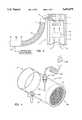
- the simulator 40includes a conduit 42 in the particular form of a right cylindrical tube.
- the conduithas an outer surface 44, an inner surface 46, and two ends, a first end being denoted by 47 and a second end by 48.
- the cylindrical tubular structure of the conduit 42enables it to contain an airflow between the two ends 47 and 48.
- a hole 50opens through the outer surface 44 into the interior of the conduit 42.
- the hole 50is preferably a circular threaded hole that is placed to position a temperature sensor in the conduit 42 where it will sense the temperature of the air flowing through the conduit 42.
- the temperature sensorindicated generally by 52, includes a thermocouple cable 53 having a thermocouple bead 54 at one end and a thermocouple coil cable 59 near another end.
- a plug 55adapts the temperature sensor 52 for being conventionally electrically connected to a measuring/recording thermometer 51 such a Fluke® model 51K/J or other, equivalent device.
- the thermocouple bead 54is kept in place by an adjustable pigtail firing including a strain relief device 56 having a threaded part 57 for engaging the threads of the circular hole 50.
- a nut 58squeezes the strain relief unit 56 around the thermocouple cable 53.
- a second circular, threaded burr-free hole 60may be provided.
- access through the burr-free hole 60is provided by a port 62 with a threaded lower portion.
- the port 62is sealed by a plug 63.
- FIG. 3shows the male luer fitting 64 of a pressure measurement tube 65 retained on the port 62.
- the tube 65is conventionally connected to a pressure measuring/recording device 66, such as a manometer.
- the second hole 60 and its associated port 62are optional and are not necessary to the practice of the invention.
- the second hole 60when the second hole 60 is provided, it should be located away from the first hole 50 in order to avoid measuring the effects of turbulence caused by the temperature sensor 52.
- the second hole 60is arcuately displaced from the first hole 50 by, for example, 90°.
- An airflow resistor 70is composed of a plurality of circular mesh screens 72 that are arranged in sequence between two circular rings 73.
- the mesh screensmay be cut from for example, 14 ⁇ 16 ⁇ 0.013" aluminum screen, which exhibits a substantially rectangular grid of fourteen wires by sixteen wires per square inch, with the diameter of the wires being 0.013 inches.
- the circular mesh screens 72are arranged so that the parallel strands in one screen are offset by rotation with respect to the corresponding strands of a preceding (or succeeding) screen. The rotation may be, for example, through an arc of 45°.
- the number of mesh screens 72is selected to give a pressure drop that is appropriate to a particular inflatable thermal blanket.
- Model 300 Full Body Inflatable Thermal Blanket available from AUGUSTINE MEDICAL, INC.is well simulated by eleven sections of mesh screen 72.
- the relation of the number of screens required to present a particular airflow resistance representing a particular inflatable thermal blanket produced by AUGUSTINE MEDICAL, INC.is given in Table I.
- the simulator 40may comprise a 6-inch length of clear polycarbonate pipe having an outside diameter of 2.5 inches and an inside diameter of 2.25 inches.
- the first (proximal) end 47 of the pipeis machined on its inner surface to accept the nozzle from an air hose.
- a temperature sensorsuch as the thermocouple bead 54 is retained on the pipe by the means described above, with the thermocouple wire entering the pipe at a right angle.
- the second (distal) end 48 of the pipecontains the airflow resistor 70 that includes a preselected number of circular mesh screens 72.
- the mesh screensare retained between two circular rings 73 that are, preferably, made of polycarbonate.
- the inventorhas constructed airflow resistors that have the structure and function of the airflow resistor 70 and that can be handled as integral units by gluing the two rings 73 together, with the circular mesh screens 72 sandwiched therebetween, using a solvent such as PVC cement.
- the outside diameters of the ringsare slightly less than the inside diameter of the conduit 42 so that the air resistor 70 can be retained in the distal end 48 of the pipe by friction or, if desired, by a solvent bond.
- an airflow resistorcan be constructed as illustrated in FIG. 3 with one, or both, of the rings 73 threaded on their outside surfaces, glued together with the circular mesh screens 72 sandwiched therebetween, and removably received in corresponding threading on the inner surface 46 of the conduit 42 at its distal end 48.
- the airflow resistance of the various blanket modelscan be simulated by selection of an airflow resistor.
- airflow resistors of varying resistancecan be formed integrally with respective conduits; alternatively, a single conduit with a threaded distal end can be provided as described above to receive a threaded airflow resistor having a selected airflow resistance that simulates the airflow resistance of a particular inflatable thermal blanket.
- the airflow resistorcan constructed in many ways. For example, a plurality of woven or non-woven fabrics can be used in place of the circular mesh screens. Alternatively, a disk of open cell type foam material can be employed. The inventor has also built airflow resistors using a plurality of small diameter tube sections, such as soda straws, packed into a honeycomb pattern. Prefabricated plastic or metal honeycomb material may also be used for airflow resistor construction. Aluminum honeycomb is available from, for example, Plascore, Inc., Zeeland, MI. Manifestly, any cross-sectional geometry can be employed both for the small tubes and for the packing pattern of the tubes.
- FIG. 5shows the simulator 40 (assembled with the temperature sensor 52 and airflow resistor 70) received on a nozzle 80 conventionally attached to the distal end 18 of the air hose 16.
- the end of the nozzle 80is received and frictionally retained in the proximal end 47 of the conduit 42.
- measurement of the airflow temperature delivered by the air source 10 through the air hose 16 at the distal end 18 of the air hosecan be understood.
- the methodtests the air source, specifically the temperature at which it delivers an airflow, by simulating an inflatable thermal blanket by means of the airflow resistor 70.
- the first end 17 of the air hose 16is coupled to the air source 10 through the coupling 14.
- the simulator 40is attached to the distal end 18 of the air hose and the air source 10 is brought to operation at a selected airflow and selected temperature.
- the airflow resistor 70presents an airflow resistance that simulates the airflow resistance of an inflatable thermal blanket
- the temperature of the airflow at the distal end 18 of the air hose 16is measured by means of the temperature sensor 52.
- the thermocouple bead 54is positioned (substantially the center of the conduit 42) the temperature flowing through, and from, the air hose 16 is measured.
- the point where the temperature is measuredis near the distal end of the air hose, which is the location at which an inflatable thermal blanket would receive the heated airflow.
- the step of coupling the simulator 40 to the distal end 18 of the air hose 16may preceded by the step of selecting an airflow resistor having a value of airflow resistance corresponding to the inflatable thermal blanket to be simulated.
- the pressure of the airflow near the distal end 18 of the air hose 16can be measured by attachment of a pressure line to the port 62 and connection of the line to a pressure measurement device, such as a manometer.
- the airflow resistance of an inflatable thermal blanketmay be measured by a test setup such as the setup illustrated in FIG. 6.
- a blower 80provides an airflow to an inflatable thermal blanket 82 through an air hose 84 having two ends, one of which is coupled to the blower 80 and the other of which is coupled to a cuff 85 that defines an inflation inlet of the inflatable thermal blanket 82.
- An autotransformer 86is conventionally connected to the motor of the blower 80 in order to vary the blower speed, and therefore the rate of airflow provided by the blower 80.
- Two instruments, an anemometer 88 and a manometer 90have respective sensors that are disposed in the air hose 84 in order to measure the airflow velocity and pressure, respectively, within the air hose 84.
- a vane 89is positioned in the air hose 84 and conventionally coupled to the anemometer 88, which enables the anemometer 88 to measure the airflow velocity and compute the flow in standard cubic feet per minute (SCFM), where standard conditions are: 1 atmosphere, 70° F.
- SCFMstandard cubic feet per minute
- the sensor that enables the manometer 90 to measure pressure in the air hose 84is positioned between the anemometer sensor 89 and the inflatable thermal blanket 82.
- the manometer sensorshould be as close as possible to the inflatable thermal blanket 82 in order to reduce the contribution to airflow resistance of the air hose 84.
- FIG. 7A typical set of resistance curves for three blower speed settings is presented in FIG. 7.
- airflow SCFMis plotted against measured pressure in inches of water (inH 2 O).
- Each of the three blower curves (X, Y, and Z) in FIG. 7illustrate the response of a blower having a fixed speed when airflow resistance is varied.
- the speed of the blower 80produces the blower curve depicted by X and the resistance of the variable airflow resistor is varied between zero and a maximum value.
- variable resistance airflow resistorWith the inflatable thermal blanket 82.
- the blower speedis varied from minimum to maximum, while the airflow characteristics of the inflatable thermal blanket 82 remain fixed.
- the curve of blanket resistance (R)exhibits a direct relationship between airflow and pressure.
- the curve R of blanket resistanceintersects the blower curves X, Y, and Z at locations that may be considered the operating points of the inflatable thermal blanket 82 in response to fixed speed blowers X, Y, and Z.
- Table Iwere obtained using the test setup illustrated in FIG. 6, with the values representing an average resistance over three fixed blower speeds.
- the simulator described and illustrated in this applicationmay be used in the factory and in the field to test and calibrate air sources.
- the airflow resistance of any inflatable thermal blanketmay be presented to an air source.
- the air sourcewould be connected to the second end of the air hose and turned on to a preselected airflow rate and temperature. While operating, the speed and temperature of the airflow delivered by the air source would be adjusted to specified standard values, with the certainty that the adjustments would reflect the actual conditions under which the air source is intended to operate.
Landscapes
- Health & Medical Sciences (AREA)
- Vascular Medicine (AREA)
- General Physics & Mathematics (AREA)
- Engineering & Computer Science (AREA)
- Biomedical Technology (AREA)
- Heart & Thoracic Surgery (AREA)
- Physics & Mathematics (AREA)
- Life Sciences & Earth Sciences (AREA)
- Animal Behavior & Ethology (AREA)
- General Health & Medical Sciences (AREA)
- Public Health (AREA)
- Veterinary Medicine (AREA)
- Thermotherapy And Cooling Therapy Devices (AREA)
Abstract
Description
TABLE I ______________________________________ BAIR HUGGER ® NUMBER OF BLANKET MODEL Airflow RESISTANCE CIRCULAR NO. (in H.sub.2 O/SCFM) MESH SCREENS ______________________________________ 305 0.0095 7 300 0.014 11 525 0.0145 11 610 o.0155 11 522 0.016 11 655 0.017 11 537 0.0175 11 310 0.018 11 315 0.018 11 540 0.018 11 530 0.018 11 110 0.022 11 650 0.027 17 536 0.031 17 ______________________________________
Claims (21)
Priority Applications (3)
| Application Number | Priority Date | Filing Date | Title |
|---|---|---|---|
| US08/697,053US5693079A (en) | 1996-08-19 | 1996-08-19 | Apparatus and method for simulating an inflatable thermal blanket to test an air source |
| US08/893,175US5876428A (en) | 1996-08-19 | 1997-07-15 | Apparatus and method for simulating an inflatable thermal blanket to test an air source |
| US09/199,718US6146412A (en) | 1996-08-19 | 1998-11-25 | Apparatus and method for simulating an inflatable thermal blanket to test an air source |
Applications Claiming Priority (1)
| Application Number | Priority Date | Filing Date | Title |
|---|---|---|---|
| US08/697,053US5693079A (en) | 1996-08-19 | 1996-08-19 | Apparatus and method for simulating an inflatable thermal blanket to test an air source |
Related Child Applications (1)
| Application Number | Title | Priority Date | Filing Date |
|---|---|---|---|
| US08/893,175DivisionUS5876428A (en) | 1996-08-19 | 1997-07-15 | Apparatus and method for simulating an inflatable thermal blanket to test an air source |
Publications (1)
| Publication Number | Publication Date |
|---|---|
| US5693079Atrue US5693079A (en) | 1997-12-02 |
Family
ID=24799611
Family Applications (3)
| Application Number | Title | Priority Date | Filing Date |
|---|---|---|---|
| US08/697,053Expired - LifetimeUS5693079A (en) | 1996-08-19 | 1996-08-19 | Apparatus and method for simulating an inflatable thermal blanket to test an air source |
| US08/893,175Expired - LifetimeUS5876428A (en) | 1996-08-19 | 1997-07-15 | Apparatus and method for simulating an inflatable thermal blanket to test an air source |
| US09/199,718Expired - LifetimeUS6146412A (en) | 1996-08-19 | 1998-11-25 | Apparatus and method for simulating an inflatable thermal blanket to test an air source |
Family Applications After (2)
| Application Number | Title | Priority Date | Filing Date |
|---|---|---|---|
| US08/893,175Expired - LifetimeUS5876428A (en) | 1996-08-19 | 1997-07-15 | Apparatus and method for simulating an inflatable thermal blanket to test an air source |
| US09/199,718Expired - LifetimeUS6146412A (en) | 1996-08-19 | 1998-11-25 | Apparatus and method for simulating an inflatable thermal blanket to test an air source |
Country Status (1)
| Country | Link |
|---|---|
| US (3) | US5693079A (en) |
Cited By (9)
| Publication number | Priority date | Publication date | Assignee | Title |
|---|---|---|---|---|
| US5876428A (en)* | 1996-08-19 | 1999-03-02 | Augustine Medical, Inc. | Apparatus and method for simulating an inflatable thermal blanket to test an air source |
| US5988876A (en)* | 1997-07-15 | 1999-11-23 | Augustine Medical, Inc. | Method for measuring temperature of an airflow for an inflatable thermal device |
| US6197045B1 (en) | 1999-01-04 | 2001-03-06 | Medivance Incorporated | Cooling/heating pad and system |
| US6245064B1 (en) | 1997-07-08 | 2001-06-12 | Atrionix, Inc. | Circumferential ablation device assembly |
| US6334228B1 (en) | 1999-10-01 | 2002-01-01 | Halo Innovations, Inc. | Apparatus, system and method for quantifying carbon dioxide dispersal on ventilated sleep surfaces |
| US6375674B1 (en) | 1999-01-04 | 2002-04-23 | Medivance, Inc. | Cooling/heating pad and system |
| US20060051204A1 (en)* | 2004-09-03 | 2006-03-09 | Lyons Leslie A | Lobed joint draft inducer blower |
| US7220273B2 (en)* | 1998-08-24 | 2007-05-22 | Arizant Healthcare Inc., | Control of airflow to an inflatable thermal device |
| US10813468B1 (en)* | 2008-07-30 | 2020-10-27 | Youngblood Ip Holdings, Llc | Multi-zone temperature modulation system for bed or blanket |
Families Citing this family (23)
| Publication number | Priority date | Publication date | Assignee | Title |
|---|---|---|---|---|
| US6440157B1 (en) | 1998-07-10 | 2002-08-27 | Respiratory Support Products Inc. | Air warming system for providing a controlled temperature of air to an air blanket |
| US6143020A (en)* | 1998-07-10 | 2000-11-07 | Respiratory Support Products, Inc. | Air warming system for providing a controlled temperature of air to an air blanket |
| US6357491B1 (en)* | 1999-07-08 | 2002-03-19 | Gaymar Industries Inc. | Controlling the misuse of an operating-room apparatus |
| US20080066484A1 (en)* | 2001-06-21 | 2008-03-20 | Blackstone Ralf W | Air cooling device |
| DE102004011139B4 (en)* | 2004-03-08 | 2011-01-20 | Dräger Safety AG & Co. KGaA | Method and device for body climate control |
| US20060016012A1 (en)* | 2004-07-21 | 2006-01-26 | Xiaoguang Liu | Device and method to prevent deep vein thrombosis |
| WO2006076148A1 (en)* | 2004-12-30 | 2006-07-20 | 3M Innovative Properties Company | Patient warming blanket |
| US7550000B2 (en)* | 2005-05-27 | 2009-06-23 | Smiths Medical Asd, Inc. | Restrictor regulated air flow blanket, system utilizing such blanket and method therefor |
| RU2378478C2 (en)* | 2006-08-29 | 2010-01-10 | Владислав Владимирович Смолянинов | Single-row rolling bearing for rotary drill |
| US20080307970A1 (en) | 2007-02-23 | 2008-12-18 | Augustine Biomedical And Design, Llc | Neck-worn air filtration device |
| AU2008218120A1 (en) | 2007-02-23 | 2008-08-28 | Augustine Biomedical And Design, Llc | Personal air filtration device |
| WO2008151426A1 (en)* | 2007-06-12 | 2008-12-18 | Kinetic Spine Technologies Inc. | Artificial intervertebral disc |
| US8057547B2 (en)* | 2007-06-12 | 2011-11-15 | Kinetic Spine Technologies Inc. | Articulating intervertebral disc prosthesis |
| US10337761B2 (en) | 2007-12-21 | 2019-07-02 | Ralf W. Blackstone | Microenvironmental cooling system |
| US20090223368A1 (en)* | 2008-03-07 | 2009-09-10 | Augustine Biomedical And Design, Llc | Distal hose end filter |
| CN202222659U (en)* | 2008-09-23 | 2012-05-23 | 莱瑞达科学公司 | Air current applying device |
| WO2010042537A1 (en)* | 2008-10-06 | 2010-04-15 | Augustine Biomedical And Design, Llc | Personal air filtration device |
| GB0919832D0 (en)* | 2009-11-13 | 2009-12-30 | Airbus Operations Ltd | Thermal test apparatus and method |
| WO2011119581A2 (en) | 2010-03-23 | 2011-09-29 | Loushin Michael K H | Gas altering convective thermoregulation blanket |
| US20110247134A1 (en)* | 2010-04-09 | 2011-10-13 | Howell Charles A | Siderail accessory module |
| US8914922B1 (en)* | 2012-03-28 | 2014-12-23 | Charles D. Wells | Mountable fan for massage table |
| USD719596S1 (en) | 2012-12-20 | 2014-12-16 | Sfs Intec Holding Ag | Induction apparatus |
| US20150320592A1 (en)* | 2014-05-09 | 2015-11-12 | Scion Neurostim, Llc | Devices, Systems and Methods for Delivering Thermal Stimulation |
Citations (12)
| Publication number | Priority date | Publication date | Assignee | Title |
|---|---|---|---|---|
| US4398535A (en)* | 1979-11-27 | 1983-08-16 | Sunset Ltd. | Hyperthermia technique |
| US4572188A (en)* | 1984-03-05 | 1986-02-25 | Augustine Scott D | Airflow cover for controlling body temperature |
| US4647219A (en)* | 1983-10-31 | 1987-03-03 | Baxter Travenol Laboratories, Inc. | Safety system for heating conduit |
| US4989456A (en)* | 1989-11-06 | 1991-02-05 | Bicore Monitoring Systems | Variable area obstruction gas flow meter |
| US5040655A (en)* | 1989-09-22 | 1991-08-20 | Pirelli Coordinamento Pneumatici S.P.A. | Variable length roller table |
| US5111827A (en)* | 1988-02-11 | 1992-05-12 | Instrumentarium Corp. | Respiratory sampling device |
| US5277196A (en)* | 1992-03-31 | 1994-01-11 | The United States Of America As Represented By The Department Of Health And Human Services | Portable spirometer with improved accuracy |
| US5300098A (en)* | 1992-05-14 | 1994-04-05 | Progressive Dynamics, Inc. | Patient warmer heater blower control |
| US5300101A (en)* | 1987-10-05 | 1994-04-05 | Augustine Medical, Inc. | Method and apparatus for treatment of pediatric hypothermia |
| US5300102A (en)* | 1987-10-05 | 1994-04-05 | Augustine Medical, Inc. | Thermal blanket |
| US5324320A (en)* | 1987-10-05 | 1994-06-28 | Augustine Medical, Inc. | Thermal blanket |
| US5405371A (en)* | 1987-10-05 | 1995-04-11 | Augustine Medical, Inc. | Thermal blanket |
Family Cites Families (4)
| Publication number | Priority date | Publication date | Assignee | Title |
|---|---|---|---|---|
| US5060655A (en)* | 1988-11-15 | 1991-10-29 | Hans Rudolph, Inc. | Pneumotach |
| US5486205A (en)* | 1994-04-18 | 1996-01-23 | Progressive Dynamics, Inc. | Diffused air heating system |
| US5785723A (en)* | 1995-10-23 | 1998-07-28 | Respiratory Support Products | Positive pressure filter system for inflatable blanket heaters |
| US5693079A (en)* | 1996-08-19 | 1997-12-02 | Augustine Medical, Inc. | Apparatus and method for simulating an inflatable thermal blanket to test an air source |
- 1996
- 1996-08-19USUS08/697,053patent/US5693079A/ennot_activeExpired - Lifetime
- 1997
- 1997-07-15USUS08/893,175patent/US5876428A/ennot_activeExpired - Lifetime
- 1998
- 1998-11-25USUS09/199,718patent/US6146412A/ennot_activeExpired - Lifetime
Patent Citations (12)
| Publication number | Priority date | Publication date | Assignee | Title |
|---|---|---|---|---|
| US4398535A (en)* | 1979-11-27 | 1983-08-16 | Sunset Ltd. | Hyperthermia technique |
| US4647219A (en)* | 1983-10-31 | 1987-03-03 | Baxter Travenol Laboratories, Inc. | Safety system for heating conduit |
| US4572188A (en)* | 1984-03-05 | 1986-02-25 | Augustine Scott D | Airflow cover for controlling body temperature |
| US5300101A (en)* | 1987-10-05 | 1994-04-05 | Augustine Medical, Inc. | Method and apparatus for treatment of pediatric hypothermia |
| US5300102A (en)* | 1987-10-05 | 1994-04-05 | Augustine Medical, Inc. | Thermal blanket |
| US5324320A (en)* | 1987-10-05 | 1994-06-28 | Augustine Medical, Inc. | Thermal blanket |
| US5405371A (en)* | 1987-10-05 | 1995-04-11 | Augustine Medical, Inc. | Thermal blanket |
| US5111827A (en)* | 1988-02-11 | 1992-05-12 | Instrumentarium Corp. | Respiratory sampling device |
| US5040655A (en)* | 1989-09-22 | 1991-08-20 | Pirelli Coordinamento Pneumatici S.P.A. | Variable length roller table |
| US4989456A (en)* | 1989-11-06 | 1991-02-05 | Bicore Monitoring Systems | Variable area obstruction gas flow meter |
| US5277196A (en)* | 1992-03-31 | 1994-01-11 | The United States Of America As Represented By The Department Of Health And Human Services | Portable spirometer with improved accuracy |
| US5300098A (en)* | 1992-05-14 | 1994-04-05 | Progressive Dynamics, Inc. | Patient warmer heater blower control |
Non-Patent Citations (2)
| Title |
|---|
| "Procedure To Check Output Temperature Of WarmTouch™ Model 5000 And Model 5100 Warming Units", Malinckrodt Medical, Inc., Anesthesiology Division, Technical Bulletin No. WT202, Mar. 3, 1993. |
| Procedure To Check Output Temperature Of WarmTouch Model 5000 And Model 5100 Warming Units , Malinckrodt Medical, Inc., Anesthesiology Division, Technical Bulletin No. WT202, Mar. 3, 1993.* |
Cited By (15)
| Publication number | Priority date | Publication date | Assignee | Title |
|---|---|---|---|---|
| US6146412A (en)* | 1996-08-19 | 2000-11-14 | Augustine Medical, Inc. | Apparatus and method for simulating an inflatable thermal blanket to test an air source |
| US5876428A (en)* | 1996-08-19 | 1999-03-02 | Augustine Medical, Inc. | Apparatus and method for simulating an inflatable thermal blanket to test an air source |
| US6245064B1 (en) | 1997-07-08 | 2001-06-12 | Atrionix, Inc. | Circumferential ablation device assembly |
| US5988876A (en)* | 1997-07-15 | 1999-11-23 | Augustine Medical, Inc. | Method for measuring temperature of an airflow for an inflatable thermal device |
| US7220273B2 (en)* | 1998-08-24 | 2007-05-22 | Arizant Healthcare Inc., | Control of airflow to an inflatable thermal device |
| US6197045B1 (en) | 1999-01-04 | 2001-03-06 | Medivance Incorporated | Cooling/heating pad and system |
| US6375674B1 (en) | 1999-01-04 | 2002-04-23 | Medivance, Inc. | Cooling/heating pad and system |
| WO2001025728A3 (en)* | 1999-10-01 | 2002-01-24 | Halo Innovations Inc | Apparatus, system and method for quantifying carbon dioxide dispersal on ventilated sleep surfaces |
| US6334228B1 (en) | 1999-10-01 | 2002-01-01 | Halo Innovations, Inc. | Apparatus, system and method for quantifying carbon dioxide dispersal on ventilated sleep surfaces |
| US20060051204A1 (en)* | 2004-09-03 | 2006-03-09 | Lyons Leslie A | Lobed joint draft inducer blower |
| US10813468B1 (en)* | 2008-07-30 | 2020-10-27 | Youngblood Ip Holdings, Llc | Multi-zone temperature modulation system for bed or blanket |
| US10986934B1 (en)* | 2008-07-30 | 2021-04-27 | Kryo, Inc. | Multi-zone temperature modulation system for bed or blanket |
| US11147389B1 (en)* | 2008-07-30 | 2021-10-19 | Kryo, Inc. | Multi-zone temperature modulation system for bed or blanket |
| US11324330B1 (en)* | 2008-07-30 | 2022-05-10 | Sleepme Inc. | Multi-zone temperature modulation system for bed or blanket |
| US11583096B1 (en)* | 2008-07-30 | 2023-02-21 | Sleepme Inc. | Multi-zone temperature modulation system for bed or blanket |
Also Published As
| Publication number | Publication date |
|---|---|
| US5876428A (en) | 1999-03-02 |
| US6146412A (en) | 2000-11-14 |
Similar Documents
| Publication | Publication Date | Title |
|---|---|---|
| US5693079A (en) | Apparatus and method for simulating an inflatable thermal blanket to test an air source | |
| US4930317A (en) | Apparatus for localized heat and cold therapy | |
| US4552059A (en) | Flow measurement for exhaust-type canopy and ventilating hood | |
| US5449275A (en) | Controller and method for operation of electric fan | |
| US6692518B2 (en) | Patient temperature control system | |
| US4759712A (en) | Device for applying controlled temperature stimuli to nerve sensitive tissue | |
| JP5074387B2 (en) | Blanket with controlled air flow in a restrictor, system, apparatus and method for using such a blanket | |
| US20020062955A1 (en) | Inflatable mannequin and system for thermal property measurement and associated methods | |
| BRPI0608706A2 (en) | system, combination and blanket for use with a fluid temperature control system | |
| JPH02193680A (en) | Humidifying device | |
| US5749259A (en) | Apparatus for simulating the thermoregulatory responses of human skin and related method for predicting fabric comfort level | |
| CN109196232A (en) | air heater | |
| US5988876A (en) | Method for measuring temperature of an airflow for an inflatable thermal device | |
| US2621297A (en) | Apparatus for measuring vapor content of gas | |
| US20170354557A1 (en) | Moisture Control System | |
| US4143649A (en) | Pump for closed circulation system | |
| US7578165B1 (en) | Measurement apparatus and methods for balloon catheters | |
| Fohimi et al. | Experimental Study of Indoor Air Temperature in the Laboratory | |
| CN111402665A (en) | System for simulating human body sweating based on fire scene condition and working method | |
| US4570493A (en) | Variable orifice air flow measuring device and method | |
| CN104807665B (en) | Humidifying capability testing device for humidifier | |
| CN211534951U (en) | Fixed heat preservation device of experimental animals | |
| JP7346244B2 (en) | Air volume adjustment method | |
| US3751634A (en) | Apparatus for measuring the degree of thermal discomfort and a system comprising such an apparatus | |
| IT202100025229A1 (en) | DEVICE FOR CONDITIONING AN AIR FLOW AND RELATED REGULATION PROCEDURE |
Legal Events
| Date | Code | Title | Description |
|---|---|---|---|
| AS | Assignment | Owner name:AUGUSTINE MEDICAL INC., MINNESOTA Free format text:ASSIGNMENT OF ASSIGNORS INTEREST;ASSIGNOR:VAN DUREN, ALBERT;REEL/FRAME:008129/0764 Effective date:19960808 | |
| STCF | Information on status: patent grant | Free format text:PATENTED CASE | |
| FPAY | Fee payment | Year of fee payment:4 | |
| AS | Assignment | Owner name:ARIZANT HEALTHCARE INC., MINNESOTA Free format text:ASSIGNMENT OF ASSIGNORS INTEREST;ASSIGNOR:AUGUSTINE MEDICAL, INC.;REEL/FRAME:013804/0785 Effective date:20030217 | |
| AS | Assignment | Owner name:MERRILL LYNCH CAPITAL, A DIVISION OF MERRILL LYNCH Free format text:SECURITY INTEREST;ASSIGNOR:ARIZANT HEALTHCARE INC.;REEL/FRAME:015629/0084 Effective date:20040730 | |
| FPAY | Fee payment | Year of fee payment:8 | |
| FPAY | Fee payment | Year of fee payment:12 | |
| AS | Assignment | Owner name:GENERAL ELECTRIC CAPITAL CORPORATION,AS ADMINISTRA Free format text:SECURITY AGREEMENT;ASSIGNOR:ARIZANT HEALTHCARE INC.;REEL/FRAME:022813/0114 Effective date:20090611 | |
| AS | Assignment | Owner name:ARIZANT HEALTHCARE INC., MINNESOTA Free format text:RELEASE BY SECURED PARTY;ASSIGNOR:GE BUSINESS FINANCIAL SERVICES INC. (F/K/A MERRILL LYNCH BUSINESS FINANCIAL SERVICES INC.), AS ADMINISTRATIVE AGENT;REEL/FRAME:022813/0325 Effective date:20090611 | |
| AS | Assignment | Owner name:GENERAL ELECTRIC CAPITAL CORPORATION, MARYLAND Free format text:ASSIGNMENT OF ASSIGNORS INTEREST;ASSIGNOR:ARIZANT HEALTHCARE INC.;REEL/FRAME:025137/0066 Effective date:20101013 | |
| AS | Assignment | Owner name:ARIZANT HEALTHCARE INC., MINNESOTA Free format text:CORRECTIVE ASSIGNMENT TO CORRECT THE NATURE OF THE CONVEYANCE AS A RELEASE BY SECURED PARTY, AND THE IDENTITY OF THE ASSIGNOR AND ASSIGNEE PREVIOUSLY RECORDED ON REEL 025137 FRAME 0066. ASSIGNOR(S) HEREBY CONFIRMS THE RELEASE OF SECURITY INTEREST IN ALL OF GRANTOR'S RIGHT, TITLE AND INTEREST IN PATENT RIGHTS;ASSIGNOR:GENERAL ELECTRIC CAPITAL CORPORATION, AS ADMINISTRATIVE AGENT;REEL/FRAME:025444/0901 Effective date:20101013 | |
| AS | Assignment | Owner name:3M INNOVATIVE PROPERTIES COMPANY, MINNESOTA Free format text:ASSIGNMENT OF ASSIGNORS INTEREST;ASSIGNOR:ARIZANT HEALTHCARE INC.;REEL/FRAME:032040/0362 Effective date:20131212 |