US5692796A - Front-end spoiler arrangement for automotive vehicle - Google Patents
Front-end spoiler arrangement for automotive vehicleDownload PDFInfo
- Publication number
- US5692796A US5692796AUS08/550,814US55081495AUS5692796AUS 5692796 AUS5692796 AUS 5692796AUS 55081495 AUS55081495 AUS 55081495AUS 5692796 AUS5692796 AUS 5692796A
- Authority
- US
- United States
- Prior art keywords
- vehicle
- under cover
- face
- section
- under
- Prior art date
- Legal status (The legal status is an assumption and is not a legal conclusion. Google has not performed a legal analysis and makes no representation as to the accuracy of the status listed.)
- Expired - Fee Related
Links
Images


Classifications
- B—PERFORMING OPERATIONS; TRANSPORTING
- B62—LAND VEHICLES FOR TRAVELLING OTHERWISE THAN ON RAILS
- B62D—MOTOR VEHICLES; TRAILERS
- B62D35/00—Vehicle bodies characterised by streamlining
- B62D35/005—Front spoilers
- Y—GENERAL TAGGING OF NEW TECHNOLOGICAL DEVELOPMENTS; GENERAL TAGGING OF CROSS-SECTIONAL TECHNOLOGIES SPANNING OVER SEVERAL SECTIONS OF THE IPC; TECHNICAL SUBJECTS COVERED BY FORMER USPC CROSS-REFERENCE ART COLLECTIONS [XRACs] AND DIGESTS
- Y02—TECHNOLOGIES OR APPLICATIONS FOR MITIGATION OR ADAPTATION AGAINST CLIMATE CHANGE
- Y02T—CLIMATE CHANGE MITIGATION TECHNOLOGIES RELATED TO TRANSPORTATION
- Y02T10/00—Road transport of goods or passengers
- Y02T10/80—Technologies aiming to reduce greenhouse gasses emissions common to all road transportation technologies
- Y02T10/82—Elements for improving aerodynamics
- Y—GENERAL TAGGING OF NEW TECHNOLOGICAL DEVELOPMENTS; GENERAL TAGGING OF CROSS-SECTIONAL TECHNOLOGIES SPANNING OVER SEVERAL SECTIONS OF THE IPC; TECHNICAL SUBJECTS COVERED BY FORMER USPC CROSS-REFERENCE ART COLLECTIONS [XRACs] AND DIGESTS
- Y10—TECHNICAL SUBJECTS COVERED BY FORMER USPC
- Y10S—TECHNICAL SUBJECTS COVERED BY FORMER USPC CROSS-REFERENCE ART COLLECTIONS [XRACs] AND DIGESTS
- Y10S180/00—Motor vehicles
- Y10S180/903—Airstream reactive vehicle or vehicle structure
Definitions
- This inventionrelates to a front-end arrangement for an automotive vehicle which is formed on an under cover of the vehicle so as to reduce a lifting force acting on front wheels, and more particularly to a front-end spoiler arrangement suitable to an automotive vehicle having a low height of chassis above ground.
- Air currents impinging on a front area of a travelling vehiclepushes the vehicle backward, and those present around the vehicle body function to lift it.
- the air resistancesuppresses the driving force of the vehicle while the lift reduces the driving force or braking force of the automotive vehicle.
- FIGS. 18 and 19 of the accompanying drawingsexemplify an air dam 1 and an under cover 2, respectively, which are used to reduce the front wheel lift.
- the air dam 1projects from an under floor of the vehicle and laterally extends thereon (i.e. in a direction perpendicular to the plane shown in FIG. 18). Air currents impinging on the air dam 1 are diverted from the front part of the vehicle, thereby increasing negative lift applied to the vehicle.
- the under cover 2 shown in FIG. 19functions to accelerate impinging air currents on its downwardly bulging part, generating a negative pressure under the vehicle and reducing the front wheel lift.
- a height of the air dam 1 or the under cover 2is limited by an approach angle ⁇ . Therefore, it is difficult to effectively reduce a coefficient of lift (C LF ). Further, it is difficult for the air dam 1 having a large form drag to reduce the air drag (a reduction of the air drag coefficient C D ).
- Japanese Utility Model Publication No. Hei 1-015,577discloses a front-end spoiler which projects in the shape of a letter V from a front under part of a vehicle. Air whirls are generated at a downstream side of the front-end spoiler, thereby preventing an excessive increase in air resistance and reducing front lift (a reduction of the front lift coefficient C LF ).
- a recessis formed on an under floor near the front wheels and at lower ends of front aprons. Air currents flowing into the recess are changed into whirls so as to produce downward force.
- the front-end spoiler in Japanese Utility Model Publication No. Hei 1-015,577is prone to a problem that its height is usually limited by the approach angle ⁇ . Therefore, the front-end spoiler cannot be high enough to sufficiently reduce the front lift. Further, because of its large form drag, it is difficult for the front-end spoiler to sufficiently reduce the air drag coefficient C D .
- the recessis formed only in an area between the front aprons and spaces before the front wheels. Thus, it is difficult to obtain sufficient downward force.
- the inventionis intended to provide a front-end spoiler arrangement which can sufficiently reduce the air drag and front lift.
- the front-end spoiler arrangementis formed on an under cover covering a front under part of an automotive vehicle, and comprises: a front part and a rear part extending between a front edge and a rear edge of the under cover, and a step formed between the front and rear parts.
- the stepdefines a space on the rear part. In this case, the space functions as a downward recess with respect to the front part.
- the stepmay have a profile of a letter V or U, or a symmetrical polygon.
- a vertex of the V-shaped or U-shaped, or polygonal stepmay coincide with a longitudinal center line of a vehicle body.
- the stepis in the shape of a rectangle whose longitudinal center line coincides with a longitudinal center line of a vehicle body.
- the front partprogressively and downwardly bulges toward a rear end of the vehicle.
- air currentscan flow smoothly on the downwardly bulging front part.
- the front part and the stepcan prevent an increase of the air drag. Further, since the bulging front part accelerates the air currents, a negative pressure can be produced under the front part. This causes the downward force which reduces the front lift.
- the rear part defining the space thereon with the stepmay be upwardly inclined toward the rear end of the vehicle. In such a case, whirls generated at the opposite ends of the step near the rear part become larger without any interference as they move toward the rear edge. This is because the rear part is upwardly inclined toward the rear end of the vehicle.
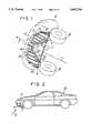
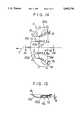
- FIG. 1is a perspective view, viewed in the direction Z shown in FIG. 2, of a front-end spoiler arrangement according to a first embodiment of the invention
- FIG. 2is a side view of a vehicle to which the front-end spoiler arrangement is applied;
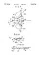
- FIG. 3is a bottom plan view of the front-end spoiler arrangement shown in FIG. 1;
- FIG. 4is a sectional view taken along line A--A of FIG. 3;
- FIG. 5is a sectional view taken along line B--B of FIG. 3;
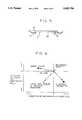
- FIG. 6is a graph showing aerodynamic characteristics of the front-end spoiler arrangement of FIG. 1 and examples of the prior art arrangements;
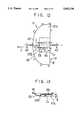
- FIG. 7is a bottom plan view of a front-end spoiler arrangement according to a second embodiment of the invention.
- FIG. 8is a sectional view taken along line A1--A1 of FIG. 7;
- FIG. 9is a sectional view taken along line B1--B1 of FIG. 7;
- FIG. 10is a bottom plan view of a front-end spoiler arrangement according to a third embodiment
- FIG. 11is a sectional view taken along line A2--A2 of FIG. 10;
- FIG. 12is a bottom plan view of a front-end spoiler arrangement according to a fourth embodiment.
- FIG. 13is a sectional view taken along line A3--A3 of FIG. 12;
- FIG. 14is a bottom plan view of a front-end spoiler arrangement according to a fifth embodiment
- FIG. 15is a sectional view taken along line A4--A4 of FIG. 14;
- FIG. 16is a bottom plan view of a front-end spoiler arrangement according to a sixth embodiment.
- FIG. 17is a sectional view taken along line A5--A5 of FIG. 16;
- FIG. 18is a side view of the air dam as a front-end spoiler arrangement of the prior art.
- FIG. 19is a side view of the under cover as a front-end spoiler arrangement of the prior art.
- FIG. 1shows a front-end spoiler arrangement according to a first embodiment of the invention.
- the front-end spoiler arrangement(called “front-end spoiler” hereinafter) is formed on an under cover 11, which is made of sheet metal and covers a front underside of an engine compartment of a vehicle 10 (not shown).
- the under cover 11is substantially in the shape of a semicircular plate, and includes a curved front edge 16, a front part 12, a rear part 14, a step 13, a pair of side portions 121, a rear end 19, and a plurality of brackets 15 positioned around a peripheral edge of the under cover 11.
- the under cover 11 and the front-end spoiler arrangementare formed as a one-piece member.
- the front part 12extends from the curved front edge 16 toward a rear end of the vehicle, and has a portion a progressively and downwardly bulging toward the rear end (called “bulging portion a).
- the bulging portion ahas a plurality of beads 17 so as to strengthen the front part 12.
- the curved front edge 16joins with the substantially straight rear edge 19.
- the side portions 121extend to the rear edge 19, and are free from the step 13.
- the side portions 121face against front wheels 18, as shown in FIG. 1 and function to control air currents f (shown in FIG. 2) such that they are downwardly diverted and are prevented from being caught by the front wheels 18.
- the side portions 121are effective in preventing an increase of the air drag.
- the step 13is formed by upwardly folding the front part 12.
- the step 13has a V-shaped profile.
- the step 13defines a space C at the rear part 14 of the under cover 11, and serves as a downward recess with respect to the front part 12.
- the rear part 14has a height h with respect to the front part 12, and is inclined with an angle ⁇ . Specifically, the rear part 14 is upwardly inclined with respect to the step 13 toward the rear edge 19. A vertex CP of the V-shaped step 13 coincides with a longitudinal center line Lc of the vehicle body (not shown).
- the brackets 15extend from the curved front edge 16 and the rear edge 19, and fasten the under cover 11 to the vehicle body using screws.
- the front-end spoilerreceives air currents f flowing toward the rear end of the vehicle.
- the air currents fflow into the space C via the downwardly bulging portion of the front part 12 (FIG. 4).
- the portion a of the front part 12progressively and downwardly bulges toward the rear end of the vehicle.
- the air currents fcan smoothly move on the bulging portion a from the curved front edge 16 of the front part 12, so the front part 12 and the step 13 can prevent the increase of the air drag.
- a negative pressure produced by the whirls sis locally and strongly applied to the rear part 14 of the under cover 11, functioning as force P to pull the vehicle downward, i.e. downward force P, as shown in FIG. 2. This prevents reduction of driving force or braking force of the vehicle.
- the V-shaped step 13the vertex of which faces in the forward direction F, directs the whirls s toward the opposite side edges (in a three-dimensional direction) of the vehicle.
- the front-end spoiler of the present inventioncan easily reduce the air drag coefficient C D .
- the whirls sadvance toward the opposite side edges of the vehicle, thereby reaching the areas inside the front wheels 18.
- Ddenotes a reference point of characteristics of the test vehicle without a front-end spoiler
- a triangle ( ⁇ )denotes characteristics of the air dam of the prior art shown in FIG. 18
- a black circle ( ⁇ )denotes characteristics of the under cover of the prior art shown in FIG. 19
- a black square ( ⁇ )denotes characteristics of the V-shaped projection as the front-end spoiler disclosed in Japanese Utility Model Publication No. Hei 1-015,577 (the data confirmed by the inventors)
- a circle ( ⁇ )denotes characteristics of the front-end spoiler according to the present invention.
- the air dam ( ⁇ ) and the under cover ( ⁇ )did not reduce the variations of the front lift coefficient ⁇ C LF and air drag coefficient ⁇ C D .
- the V-shaped projection ( ⁇ )reduced the variation of the front lift coefficient ⁇ C LF , but positively increased the variation of the air drag coefficient ⁇ C D .
- the front-end spoiler (O) of the present inventionprevented positive increases in the variation of the front lift coefficient ⁇ C LF and reduced the variation of the air drag coefficient ⁇ C D . This means that the front-end spoiler of the present invention can generate the downward force P for reducing the front lift and, effectively prevent the reduction of driving force and braking force of the vehicle.
- the under cover 11is made of sheet metal.
- an under cover 20 made of resinmay be used as shown in FIGS. 7 to 9 related to a second embodiment of the invention.
- the under cover 20is substantially in the shape of a thick semicircular plate, and has a curved front edge 16, a front part 12a, a ridge 122a, a step 13a, a pair of side portions 121a, and a rear part 14a.
- the step 13adefines a space Ca at the rear part 14a.
- the space Cais similar to the space C in the first embodiment, and is higher than the front part 12a by a height h.
- the foregoing componentsare formed as a one-piece member.
- the side portions 121a facing against the front wheels 18guide air currents f downward, and prevent them from being caught by the front wheels 18 and prevent the increase of the air resistance.
- the under cover 20is screwed on the vehicle body using brackets (not shown) along the curved front edge 16 and the rear edge 22.
- the front-end spoiler of the second embodimentchanges air currents f into whirls s at the V-shaped step 13a.
- the whirls sare diverted toward areas inside the front wheels 18.
- a negative pressureis caused by the whirls s at the rear part 14a, which applies the downward force P to the front wheels 18 so as to reduce the front lift and prevent the reduction of the driving or braking force. Since the front part 12a progressively and downwardly bulges toward the rear end of the vehicle body, the front part 12a and the step 13a can prevent an increase of the air drag.
- the whirls s generated by the step 13areach the areas inside the front wheels 18, so a negative pressure can be guided to disc brakes (not shown), which is effective in cooling the disc brakes.
- the under cover 20 made of resinis light in weight.
- FIG. 10shows a front-end spoiler according to a third embodiment of the invention.
- This embodimentfeatures a space Cb whose shape differs from the space C of the first embodiment. Therefore, identical parts have identical reference numbers, and will not be repeatedly described in detail.
- the front-end spoileris formed on the under cover 11 made of sheet metal, and includes a curved front edge 16, a front part 12b, a ridge 122b, a step 13b, side portions 121b, a rear part 14b, and a rear edge 19.
- the step 13bdefines the space Cb at the rear part 14b.
- the side portions 121bare free from the step 13b, and extend to the rear edge 19.
- the step 13bhas a profile in the shape of a letter U, of which vertex CP coincides with the longitudinal center line Lc of the vehicle body.
- the U-shaped step 13bdiverts them as whirls s obliquely advancing right and left toward the opposite sides edges of the vehicle.
- the whirls sgenerate a negative pressure on the rear part 14b, which generates the downward force P for reducing the front lift, and prevents the reduction of the driving or braking force of the vehicle.
- the front part 12bprogressively and downwardly bulges such that it can prevent an increase of the air drag together with the step 13b.
- the step 13bis also effective in assuring a reduced air drag coefficient C D .
- a front-end spoiler according to a fourth embodimentwill be described with reference to FIGS. 12 and 13. This embodiment differs from the first embodiment in the shape of a space Cc.
- the front-end spoileris formed on the under cover 11 made of a sheet metal, and includes a curved front edge 16, a front part 12c, a step 13c, a ridge 122c, a rear part 14c, a pair of side portions 121c, and a rear edge 19.
- the side portions 121care free from the step 13c, and extend to the rear edge 19.
- the step 13c and the rear edge 19define the space Cc in the shape of a rectangle.
- a longitudinal center CP' of the rectangular space Cccoincides with the longitudinal center line Lc of the vehicle body.
- Air currents f striking the front-end spoilerare changed into whirls s by a linear portion of the step 13c, and these whirls flow toward the rear end of the vehicle.
- the whirls scause a negative pressure on the rear part 14b of the under cover 11, which serves as a downward force P to reduce the front lift, and prevents reduction of the driving or braking force.
- the front part 12cprogressively and downwardly bulges toward the rear end of the vehicle, so it can prevent an increase of the air drag together with the step 13c.
- FIG. 14shows a front-end spoiler according to a fifth embodiment. This embodiment differs from the first embodiment of FIG. 1 in the shape of a space Cd, which will be described in detail. The other components are substantially the same as those in the first embodiment, and will not be repeatedly described here.
- the front-end spoileris formed on the under cover 11, and includes a curved front edge 16, a front part 12d, a ridge 122d, a step 13d, a pair of side portions 121d, a rear part 14d, and a rear edge 19.
- the step 13ddefines a polygonal space Cd at the rear part 14d.
- the space Cdis higher than the front part 12d by a height h.
- the side portions 121dare free from the step 13d, and extends to the rear edge 19.
- the step 13dhas a polygonal profile.
- a center line CP halving a straight portion 131d of the polygonal step 13dcoincides with the longitudinal center line Lc of the vehicle body.
- the polygonal step 13bdiverts them as whirls s obliquely advancing toward the opposite side edges of the vehicle.
- the whirls sgenerate a negative pressure in the space Cd on the rear part 14d, which in turn generates the downward force P for reducing the front lift P, which prevents the reduction of the driving or braking force of the vehicle.
- the front part 12dprogressively and downwardly bulges such that it can prevent an increase of the air drag together with the step 13d.
- the step 13dis also effective in assuring the reduction of the air drag coefficient C D .
- FIG. 16shows a front-end spoiler according to a sixth embodiment. This embodiment differs from the first embodiment of FIG. 1 in the shape of a space Ce, which will be described in detail. The other components are substantially the same as those in the first embodiment, and will not be repeatedly described here.
- the front-end spoileris formed on the under cover 11, and includes a curved front edge 16, a front part 12e, a ridge 122e, a step 133e, a pair of side portions 121e, a rear part 14e, and rear edge 19.
- the step 13edefines a modified polygonal space Cd at the rear part 14e.
- the space Ceis higher than the front part 12e by a height h.
- the side portions 121eare free from the step 13e, and extend to the rear edge 19.
- the step 13dhas a modified polygonal profile having a center V-shaped portion 131e and a pair of sawtoothed projections having portions 132e and 133e.
- a Vertex CP of the V-shaped portion 131e of the modified polygonal step 13ecoincides with the longitudinal center line Lc of the vehicle body.
- the polygonal step 13ediverts them as whirls s obliquely advancing right and left toward the opposite sides of the vehicle.
- the whirls sgenerate a negative pressure in the space Ce at the rear part 14e, thus producing the downward force P for reducing the front lift, and preventing the reduction of the driving or braking force of the vehicle.
- the front part 12eprogressively and downwardly bulges such that it can prevent an increase of the air drag together with the step 13e.
- the step 13eis also effective in assuring the reduction of the air drag coefficient C D .
- the rear parts 14a to 14ehave the spaces Ca to Ce which are higher than the front parts 12a to 12e by the height h.
- the rear ends 14a to 14emay be upwardly inclined toward the rear end of the vehicle as shown by dashed lines in FIGS. 8, 11, 13, 15 and 17. In such a case, the whirls s generated near the rear parts 14a to 14e can become larger without obstruction, and cause downward force P, which reliably reduce the lift to be applied to the front wheels.
- the front-end spoiler arrangements of the present inventionare applicable to automotive vehicles having a reduced height of chassis above ground which is affected by the approach angle ⁇ . These front-end spoiler are effective in improving acceleration and braking force.
Landscapes
- Engineering & Computer Science (AREA)
- Chemical & Material Sciences (AREA)
- Combustion & Propulsion (AREA)
- Transportation (AREA)
- Mechanical Engineering (AREA)
- Body Structure For Vehicles (AREA)
Abstract
Description
Claims (21)
Applications Claiming Priority (2)
| Application Number | Priority Date | Filing Date | Title |
|---|---|---|---|
| JP6267267AJPH08127367A (en) | 1994-10-31 | 1994-10-31 | Front wheel lift reduction device |
| JP6-267267 | 1994-10-31 |
Publications (1)
| Publication Number | Publication Date |
|---|---|
| US5692796Atrue US5692796A (en) | 1997-12-02 |
Family
ID=17442472
Family Applications (1)
| Application Number | Title | Priority Date | Filing Date |
|---|---|---|---|
| US08/550,814Expired - Fee RelatedUS5692796A (en) | 1994-10-31 | 1995-10-31 | Front-end spoiler arrangement for automotive vehicle |
Country Status (4)
| Country | Link |
|---|---|
| US (1) | US5692796A (en) |
| EP (1) | EP0709280B1 (en) |
| JP (1) | JPH08127367A (en) |
| DE (1) | DE69512176T2 (en) |
Cited By (23)
| Publication number | Priority date | Publication date | Assignee | Title |
|---|---|---|---|---|
| US6070933A (en)* | 1996-04-26 | 2000-06-06 | Nissan Motor Co., Ltd. | Automotive front lower structure |
| US20030116996A1 (en)* | 2001-12-11 | 2003-06-26 | Heinz Soja | Motor vehicle having a front end comprising an air-guiding device and method of making and using same |
| US20050121945A1 (en)* | 2003-12-04 | 2005-06-09 | Browne Alan L. | Airflow control devices based on active materials |
| US20050121240A1 (en)* | 2003-12-04 | 2005-06-09 | Aase Jan H. | Airflow control devices based on active materials |
| US20050194815A1 (en)* | 2003-12-04 | 2005-09-08 | Mc Knight Geoffrey P. | Airflow control devices based on active materials |
| US20080035400A1 (en)* | 2006-08-08 | 2008-02-14 | Paccar Inc | Airflow diverter |
| US20080272615A1 (en)* | 2004-11-05 | 2008-11-06 | General Motors Corporation | Airflow control devices based on active materials |
| US20090115221A1 (en)* | 2007-11-05 | 2009-05-07 | Michael Shinedling | Adjustable aerodynamic splitter |
| US20100072777A1 (en)* | 2008-09-25 | 2010-03-25 | Honda Motor Co., Ltd. | Front fascia plasma-induced drag reduction device |
| US20100219661A1 (en)* | 2009-03-02 | 2010-09-02 | Gm Global Technology Operations, Inc. | Extendable Air Control Dam for Vehicle |
| US20120013146A1 (en)* | 2010-07-16 | 2012-01-19 | Dr. Ing. H.C.F. Porsche Aktiengesellschaft | Air guiding device |
| US8210600B1 (en)* | 2011-01-05 | 2012-07-03 | Ford Global Technologies, Llc | Aerodynamic package for an automotive vehicle |
| US20140070564A1 (en)* | 2012-09-11 | 2014-03-13 | Hendrickson Usa, L.L.C. | Air flow control assembly for a motor vehicle |
| US20150175222A1 (en)* | 2013-12-20 | 2015-06-25 | Apollo Tyres Global R&D B.V. | Vehicle front spoiler |
| US9108580B2 (en) | 2013-04-11 | 2015-08-18 | Shape Corp. | Bumper system with pedestrian-friendly lower apron |
| US20150232138A1 (en)* | 2012-09-21 | 2015-08-20 | Mclaren Automotive Limited | Devices for controlling the downforce generated by a vehicle |
| US20150336615A1 (en)* | 2014-05-22 | 2015-11-26 | Hanwha Advanced Materials Corporation | Car undercover |
| US9266571B2 (en) | 2013-03-05 | 2016-02-23 | Joseph D'Arcy | Speed-adaptive wing for drag reduction |
| US10214255B1 (en)* | 2017-11-06 | 2019-02-26 | Yoshitaka Suzuka | Undercarriage panel for increasing fuel efficiency by reducing drag of a vehicle |
| US11059441B2 (en)* | 2015-08-14 | 2021-07-13 | Scrape Armor, Inc. | Vehicle protection apparatus |
| US20230234524A1 (en)* | 2019-11-05 | 2023-07-27 | Scott Whitehead | Vehicle protection adapter |
| US11794825B2 (en)* | 2020-07-28 | 2023-10-24 | Honda Motor Co., Ltd. | Undercover structure |
| US20240109506A1 (en)* | 2015-08-14 | 2024-04-04 | Scrape Armor, Inc. | Vehicle protection adapter |
Families Citing this family (7)
| Publication number | Priority date | Publication date | Assignee | Title |
|---|---|---|---|---|
| GB2300607B (en)* | 1995-05-11 | 1998-09-02 | Draftex Ind Ltd | Vehicle undershielding arrangements |
| DE19744601B4 (en)* | 1997-10-09 | 2008-12-11 | Volkswagen Ag | Engine compartment bulkhead in the front area of a vehicle |
| DE102004061835A1 (en)* | 2004-12-22 | 2006-07-06 | Bayerische Motoren Werke Ag | spoiler device |
| JP4850567B2 (en)* | 2006-04-13 | 2012-01-11 | 小島プレス工業株式会社 | Vehicle under cover |
| DE102007045004A1 (en)* | 2007-09-20 | 2009-04-02 | Bayerische Motoren Werke Aktiengesellschaft | spoiler device |
| JP6670338B2 (en)* | 2018-03-30 | 2020-03-18 | 株式会社ホンダアクセス | Rectifying fin |
| WO2024161296A1 (en)* | 2023-01-31 | 2024-08-08 | Waldner Alessio | Protection shield for the front wing of passenger cars |
Citations (7)
| Publication number | Priority date | Publication date | Assignee | Title |
|---|---|---|---|---|
| FR1336673A (en)* | 1962-03-08 | 1963-09-06 | Method for improving the road holding of automobiles | |
| FR1529933A (en)* | 1967-05-12 | 1968-06-21 | Device used to increase the grip of vehicles at high speeds | |
| JPS545460A (en)* | 1977-06-14 | 1979-01-16 | Matsushita Electric Ind Co Ltd | Bodily temperatuer measuring device |
| DE8505038U1 (en)* | 1985-02-22 | 1985-05-15 | Dr.Ing.H.C. F. Porsche Ag, 7000 Stuttgart | AERODYNAMIC FAIRING ON THE BOTTOM OF PERSONAL CARS |
| JPS6415577A (en)* | 1987-07-10 | 1989-01-19 | Yazaki Corp | Switching valve |
| US4810021A (en)* | 1985-11-30 | 1989-03-07 | Dr.-Ing H.C.F. Porsche Aktiengesellschaft | Aerodynamic brake cooling spoiler |
| JPH02303980A (en)* | 1989-05-18 | 1990-12-17 | Nissan Motor Co Ltd | Automobile underfloor structure |
- 1994
- 1994-10-31JPJP6267267Apatent/JPH08127367A/enactivePending
- 1995
- 1995-10-31EPEP95307770Apatent/EP0709280B1/ennot_activeExpired - Lifetime
- 1995-10-31USUS08/550,814patent/US5692796A/ennot_activeExpired - Fee Related
- 1995-10-31DEDE69512176Tpatent/DE69512176T2/ennot_activeExpired - Fee Related
Patent Citations (7)
| Publication number | Priority date | Publication date | Assignee | Title |
|---|---|---|---|---|
| FR1336673A (en)* | 1962-03-08 | 1963-09-06 | Method for improving the road holding of automobiles | |
| FR1529933A (en)* | 1967-05-12 | 1968-06-21 | Device used to increase the grip of vehicles at high speeds | |
| JPS545460A (en)* | 1977-06-14 | 1979-01-16 | Matsushita Electric Ind Co Ltd | Bodily temperatuer measuring device |
| DE8505038U1 (en)* | 1985-02-22 | 1985-05-15 | Dr.Ing.H.C. F. Porsche Ag, 7000 Stuttgart | AERODYNAMIC FAIRING ON THE BOTTOM OF PERSONAL CARS |
| US4810021A (en)* | 1985-11-30 | 1989-03-07 | Dr.-Ing H.C.F. Porsche Aktiengesellschaft | Aerodynamic brake cooling spoiler |
| JPS6415577A (en)* | 1987-07-10 | 1989-01-19 | Yazaki Corp | Switching valve |
| JPH02303980A (en)* | 1989-05-18 | 1990-12-17 | Nissan Motor Co Ltd | Automobile underfloor structure |
Cited By (47)
| Publication number | Priority date | Publication date | Assignee | Title |
|---|---|---|---|---|
| US6070933A (en)* | 1996-04-26 | 2000-06-06 | Nissan Motor Co., Ltd. | Automotive front lower structure |
| US7040690B2 (en)* | 2001-12-11 | 2006-05-09 | Dr. Ing H.C.F. Porsche Ag | Motor vehicle having a front end comprising an air-guiding device and method of making and using same |
| US20030116996A1 (en)* | 2001-12-11 | 2003-06-26 | Heinz Soja | Motor vehicle having a front end comprising an air-guiding device and method of making and using same |
| US7703839B2 (en) | 2003-12-04 | 2010-04-27 | Gm Global Technology Operations, Inc. | Airflow control devices based on active materials |
| US20050194815A1 (en)* | 2003-12-04 | 2005-09-08 | Mc Knight Geoffrey P. | Airflow control devices based on active materials |
| US20050230546A1 (en)* | 2003-12-04 | 2005-10-20 | Mc Knight Geoffrey P | Airflow control devices based on active materials |
| US6979050B2 (en)* | 2003-12-04 | 2005-12-27 | General Motors Corporation | Airflow control devices based on active materials |
| US20060049666A1 (en)* | 2003-12-04 | 2006-03-09 | General Motors Corporation | Airflow control devices based on active materials |
| US20050121240A1 (en)* | 2003-12-04 | 2005-06-09 | Aase Jan H. | Airflow control devices based on active materials |
| US7059664B2 (en) | 2003-12-04 | 2006-06-13 | General Motors Corporation | Airflow control devices based on active materials |
| US20060214469A1 (en)* | 2003-12-04 | 2006-09-28 | General Motors Corporation | Airflow control devices based on active materials |
| US7118652B2 (en)* | 2003-12-04 | 2006-10-10 | General Motors Corporation | Airflow control devices based on active materials |
| US20060267376A1 (en)* | 2003-12-04 | 2006-11-30 | Mcknight Geoffrey P | Airflow control devices based on active materials |
| US7147271B2 (en) | 2003-12-04 | 2006-12-12 | General Motors Corporation | Airflow control devices with planar surfaces |
| US7147269B2 (en) | 2003-12-04 | 2006-12-12 | General Motors Corporation | Airflow control devices using current |
| US7178859B2 (en) | 2003-12-04 | 2007-02-20 | General Motors Corporation | Method for controlling airflow |
| US20050121945A1 (en)* | 2003-12-04 | 2005-06-09 | Browne Alan L. | Airflow control devices based on active materials |
| US7429074B2 (en) | 2003-12-04 | 2008-09-30 | General Motors Corporation | Airflow control devices based on active materials |
| US7854467B2 (en) | 2004-11-05 | 2010-12-21 | General Motors Corporation | Airflow control devices based on active materials |
| US20080272615A1 (en)* | 2004-11-05 | 2008-11-06 | General Motors Corporation | Airflow control devices based on active materials |
| US20080035400A1 (en)* | 2006-08-08 | 2008-02-14 | Paccar Inc | Airflow diverter |
| US20090115221A1 (en)* | 2007-11-05 | 2009-05-07 | Michael Shinedling | Adjustable aerodynamic splitter |
| US7661753B2 (en)* | 2007-11-05 | 2010-02-16 | Chrysler Group Llc | Adjustable aerodynamic splitter |
| US20100072777A1 (en)* | 2008-09-25 | 2010-03-25 | Honda Motor Co., Ltd. | Front fascia plasma-induced drag reduction device |
| US7887119B2 (en) | 2008-09-25 | 2011-02-15 | Honda Motor Co., Ltd. | Front fascia plasma-induced drag reduction device |
| US20100219661A1 (en)* | 2009-03-02 | 2010-09-02 | Gm Global Technology Operations, Inc. | Extendable Air Control Dam for Vehicle |
| US8100460B2 (en)* | 2009-03-02 | 2012-01-24 | GM Global Technology Operations LLC | Extendable air control dam for vehicle |
| US20120013146A1 (en)* | 2010-07-16 | 2012-01-19 | Dr. Ing. H.C.F. Porsche Aktiengesellschaft | Air guiding device |
| US8297685B2 (en)* | 2010-07-16 | 2012-10-30 | Dr. Ing. H.C.F. Porsche Aktiengesellschaft | Air guiding device |
| US8210600B1 (en)* | 2011-01-05 | 2012-07-03 | Ford Global Technologies, Llc | Aerodynamic package for an automotive vehicle |
| US20140070564A1 (en)* | 2012-09-11 | 2014-03-13 | Hendrickson Usa, L.L.C. | Air flow control assembly for a motor vehicle |
| US9561827B2 (en)* | 2012-09-21 | 2017-02-07 | McLaren Technology Centre | Devices for controlling the downforce generated by a vehicle |
| US10106211B2 (en)* | 2012-09-21 | 2018-10-23 | Mclaren Automotive Limited | Adjustable component cooling device for controlling downforce generated by a vehicle |
| US10099731B2 (en)* | 2012-09-21 | 2018-10-16 | Mclaren Automotive Limited | Devices for controlling the downforce generated by a vehicle during cornering |
| US10752303B2 (en)* | 2012-09-21 | 2020-08-25 | Mclaren Automotive Limited | Component for controlling downforce generated by a vehicle |
| US20150232138A1 (en)* | 2012-09-21 | 2015-08-20 | Mclaren Automotive Limited | Devices for controlling the downforce generated by a vehicle |
| US9266571B2 (en) | 2013-03-05 | 2016-02-23 | Joseph D'Arcy | Speed-adaptive wing for drag reduction |
| US9108580B2 (en) | 2013-04-11 | 2015-08-18 | Shape Corp. | Bumper system with pedestrian-friendly lower apron |
| US9394012B2 (en)* | 2013-12-20 | 2016-07-19 | Apollo Tyres Global R&D B.V. | Vehicle front spoiler |
| US20150175222A1 (en)* | 2013-12-20 | 2015-06-25 | Apollo Tyres Global R&D B.V. | Vehicle front spoiler |
| US9650077B2 (en)* | 2014-05-22 | 2017-05-16 | Hanwha Advanced Materials Corporation | Car undercover |
| US20150336615A1 (en)* | 2014-05-22 | 2015-11-26 | Hanwha Advanced Materials Corporation | Car undercover |
| US11059441B2 (en)* | 2015-08-14 | 2021-07-13 | Scrape Armor, Inc. | Vehicle protection apparatus |
| US20240109506A1 (en)* | 2015-08-14 | 2024-04-04 | Scrape Armor, Inc. | Vehicle protection adapter |
| US10214255B1 (en)* | 2017-11-06 | 2019-02-26 | Yoshitaka Suzuka | Undercarriage panel for increasing fuel efficiency by reducing drag of a vehicle |
| US20230234524A1 (en)* | 2019-11-05 | 2023-07-27 | Scott Whitehead | Vehicle protection adapter |
| US11794825B2 (en)* | 2020-07-28 | 2023-10-24 | Honda Motor Co., Ltd. | Undercover structure |
Also Published As
| Publication number | Publication date |
|---|---|
| DE69512176T2 (en) | 2000-04-27 |
| EP0709280B1 (en) | 1999-09-15 |
| EP0709280A2 (en) | 1996-05-01 |
| EP0709280A3 (en) | 1997-08-13 |
| JPH08127367A (en) | 1996-05-21 |
| DE69512176D1 (en) | 1999-10-21 |
Similar Documents
| Publication | Publication Date | Title |
|---|---|---|
| US5692796A (en) | Front-end spoiler arrangement for automotive vehicle | |
| US8210600B1 (en) | Aerodynamic package for an automotive vehicle | |
| US6435298B1 (en) | Vehicle rear underside structure | |
| US10933927B2 (en) | Airflow deflector for a vehicle | |
| JPS6253287A (en) | A car with an air guide device installed on the body side | |
| CN110431066B (en) | Aerodynamic part for automobile | |
| US11623700B2 (en) | Multi-panel skirt system for cargo enclosures | |
| US20040155485A1 (en) | Deflector for the air-flow in a motor-vehicle | |
| JP2004345562A (en) | Automotive air drag reduction device | |
| JP2002362429A (en) | Under-floor structure of car | |
| US5941595A (en) | Method and apparatus for reducing lift and drag of a soft top passenger vehicle | |
| US20230278649A1 (en) | Vehicle with undercover | |
| JPH06227436A (en) | Air guide structure for vehicle wheel house | |
| CA1084082A (en) | Drag reducer for land vehicles | |
| JP3055409B2 (en) | Lift reduction device | |
| US10393003B2 (en) | Stamped aerodynamic deflector for vehicle muffler | |
| US20210354767A1 (en) | Airflow deflector for vehicle | |
| JP3055410B2 (en) | Lift reduction device | |
| JP2842119B2 (en) | Vehicle air flow control device | |
| KR200181787Y1 (en) | Downforce device of car | |
| GB2247867A (en) | Aerodynamic device for vehicle bonnet | |
| JPH0423117Y2 (en) | ||
| US5823609A (en) | Forward tilt windshield | |
| GB1576972A (en) | Aerodynamic drag reducer for vehicles | |
| KR20240126136A (en) | Drag-reducing device for commercial vehicle |
Legal Events
| Date | Code | Title | Description |
|---|---|---|---|
| AS | Assignment | Owner name:MITSUBISHI JIDOSHA KOGYO KABUSHIKI KAISHA, JAPAN Free format text:ASSIGNMENT OF ASSIGNORS INTEREST;ASSIGNORS:YAMAMOTO, SATORU;YANAGIMOTO, KAZUO;KANIE, KEISUKE;AND OTHERS;REEL/FRAME:007782/0140 Effective date:19951019 | |
| FEPP | Fee payment procedure | Free format text:PAYOR NUMBER ASSIGNED (ORIGINAL EVENT CODE: ASPN); ENTITY STATUS OF PATENT OWNER: LARGE ENTITY | |
| FPAY | Fee payment | Year of fee payment:4 | |
| AS | Assignment | Owner name:MITSUBISHI JIDOSHA KOGYO K.K. (A.K.A. MITSUBISHI M Free format text:CHANGE OF ADDRESS;ASSIGNOR:MITSUBISHI JIDOSHA KOGYO K.K.;REEL/FRAME:014601/0865 Effective date:20030905 | |
| FPAY | Fee payment | Year of fee payment:8 | |
| AS | Assignment | Owner name:MITSUBISHI JIDOSHA KOGYO K.K. (A.K.A. MITSUBISHI M Free format text:CHANGE OF ADDRESS;ASSIGNOR:MITSUBISHI JIDOSHA KOGYO K.K. (A.K.A. MITSUBISHI MOTORS CORPORATION);REEL/FRAME:019019/0761 Effective date:20070101 | |
| REMI | Maintenance fee reminder mailed | ||
| LAPS | Lapse for failure to pay maintenance fees | ||
| STCH | Information on status: patent discontinuation | Free format text:PATENT EXPIRED DUE TO NONPAYMENT OF MAINTENANCE FEES UNDER 37 CFR 1.362 | |
| FP | Lapsed due to failure to pay maintenance fee | Effective date:20091202 |