US5692054A - Multiple source self noise cancellation - Google Patents
Multiple source self noise cancellationDownload PDFInfo
- Publication number
- US5692054A US5692054AUS08/411,785US41178595AUS5692054AUS 5692054 AUS5692054 AUS 5692054AUS 41178595 AUS41178595 AUS 41178595AUS 5692054 AUS5692054 AUS 5692054A
- Authority
- US
- United States
- Prior art keywords
- phenomena
- repetitive
- unwanted
- controller system
- canceling
- Prior art date
- Legal status (The legal status is an assumption and is not a legal conclusion. Google has not performed a legal analysis and makes no representation as to the accuracy of the status listed.)
- Expired - Fee Related
Links
Images


Classifications
- F—MECHANICAL ENGINEERING; LIGHTING; HEATING; WEAPONS; BLASTING
- F04—POSITIVE - DISPLACEMENT MACHINES FOR LIQUIDS; PUMPS FOR LIQUIDS OR ELASTIC FLUIDS
- F04D—NON-POSITIVE-DISPLACEMENT PUMPS
- F04D29/00—Details, component parts, or accessories
- F04D29/66—Combating cavitation, whirls, noise, vibration or the like; Balancing
- F04D29/661—Combating cavitation, whirls, noise, vibration or the like; Balancing especially adapted for elastic fluid pumps
- F04D29/663—Sound attenuation
- F04D29/665—Sound attenuation by means of resonance chambers or interference
- F—MECHANICAL ENGINEERING; LIGHTING; HEATING; WEAPONS; BLASTING
- F24—HEATING; RANGES; VENTILATING
- F24F—AIR-CONDITIONING; AIR-HUMIDIFICATION; VENTILATION; USE OF AIR CURRENTS FOR SCREENING
- F24F13/00—Details common to, or for air-conditioning, air-humidification, ventilation or use of air currents for screening
- F24F13/24—Means for preventing or suppressing noise
- F24F2013/247—Active noise-suppression
- G—PHYSICS
- G10—MUSICAL INSTRUMENTS; ACOUSTICS
- G10K—SOUND-PRODUCING DEVICES; METHODS OR DEVICES FOR PROTECTING AGAINST, OR FOR DAMPING, NOISE OR OTHER ACOUSTIC WAVES IN GENERAL; ACOUSTICS NOT OTHERWISE PROVIDED FOR
- G10K2210/00—Details of active noise control [ANC] covered by G10K11/178 but not provided for in any of its subgroups
- G10K2210/10—Applications
- G10K2210/109—Compressors, e.g. fans
- G—PHYSICS
- G10—MUSICAL INSTRUMENTS; ACOUSTICS
- G10K—SOUND-PRODUCING DEVICES; METHODS OR DEVICES FOR PROTECTING AGAINST, OR FOR DAMPING, NOISE OR OTHER ACOUSTIC WAVES IN GENERAL; ACOUSTICS NOT OTHERWISE PROVIDED FOR
- G10K2210/00—Details of active noise control [ANC] covered by G10K11/178 but not provided for in any of its subgroups
- G10K2210/10—Applications
- G10K2210/123—Synchrophasors or other applications where multiple noise sources are driven with a particular phase relationship
- G—PHYSICS
- G10—MUSICAL INSTRUMENTS; ACOUSTICS
- G10K—SOUND-PRODUCING DEVICES; METHODS OR DEVICES FOR PROTECTING AGAINST, OR FOR DAMPING, NOISE OR OTHER ACOUSTIC WAVES IN GENERAL; ACOUSTICS NOT OTHERWISE PROVIDED FOR
- G10K2210/00—Details of active noise control [ANC] covered by G10K11/178 but not provided for in any of its subgroups
- G10K2210/30—Means
- G10K2210/301—Computational
- G10K2210/3026—Feedback
Definitions
- This inventionrelates to a unique method of canceling noise or vibration where two or more noisy sources are employed.
- the tonal noise or vibrationis canceled without the use of a loudspeaker or other transducer.
- the present inventionrefers to a method of canceling tonal noise (or vibration) generated by sources such as fans when installed into an appropriate apparatus to produce air flow.
- sourcessuch as fans when installed into an appropriate apparatus to produce air flow.
- These fansusually have backward curved or backward inclined blades on the actual fan wheel.
- the wheelis installed into a housing with a certain scroll associated with it. Part of the scroll is a cutoff where the air flow is directed out the outlet of the housing. As the blades pass the cutoff, pressure pulses associated with them strike the cutoff and produce a tonal frequency equal to the rotational frequency times the number of blades on the wheel.
- Typical installationsmight create tonals from 50 to 2000 Hz. At these frequencies, passive silencing is not feasible due to the large amount of material necessary for these low frequencies. Therefore, active noise cancellation can be used.
- the present inventionemploys some of the teachings of the MISACT algorithm. It includes the use of two or more rotating, tonal noise generating devices in conjunction with MISACT to cancel the tonal noise produced.
- the MISACT algorithmgenerates a control signal to synchronize the devices thereby minimizing the tonal noise at a specific location such as a fan inlet, outlet or both.
- the inventionincludes methods to adjust the relative phase of noise producing pressure pulses.
- Thiscan include multiple motors with single fan wheels or single motors with multiple fan wheels, for example.
- Thiscan also include two or more motors mounted on a single plate.
- the procedure in both systemsis, given a certain motor or engine speed, to adjust the relative times at which the pressure pulses generate the noise so that at the error sensor the tonal noise is minimized.
- the great advantage to this approachis that no acoustic actuator such as a speaker or electromagnetic current is needed.
- the life of the canceling systemwill be as long at the motor and will not be limited by the speaker cone life.
- Another object of this inventionis to provide a method and device for canceling tonal noise in a system having a single fan on each multiple motor.
- a further object of this inventionis to provide a method and device for canceling tonal noise in a system having a single motor and multiple fans.
- a still further object of this inventionis to provide a method of canceling tonal noise in a system with multiple fans by adjusting the phase angle between the fans.
- Another object of this inventionis to provide a tonal noise canceling system without the use of an acoustic actuator.
- Another object of this inventionis to provide tonal vibration cancellation by adjusting the relative rotation between two co-located rotating machines without the use of an electromagnetic actuator.
- FIG. 1is a diagrammatic view of a two motor, two fan system
- FIG. 2is a diagrammatic view of a one motor, two fan system
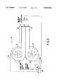
- FIG. 3is a semi-diagrammatic view of self cancellation using two fans as sources
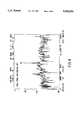
- FIGS. 4 and 5show the effect on tonal noise when running with dual tonal fan phase control off and on, respectively.
- FIG. 1depicts a two motor/two fan system 10.
- the blades or fans 11, 12can be rotating in the same direction or counter rotating. It is assumed that they are installed into a housing where the passage of the blades creates tonal noise.
- One motor 13is chosen as the reference with its rotation rate being the basic sync signal for the system
- the syncwill also serve as input 1 to the MISACT system.
- Input 2is another position signal that will be used by the MISACT algorithm processor 15 as a measure of the relative position of blade 12 versus blade 11.
- MISACTwill keep the blades rotating at the same angular frequency but will adjust the relative times that the blades in each wheel go past the cutoffs in the housing. Thus, by adjusting that timing, MISACT will reduce the acoustic noise sensed at the error sensor 15.
- the synchronizing signalcan be magnetic, optical or acoustic in nature and the sensor signal can be inductive or capacitive.
- FIG. 2is another two bladed system 20 but with both blades 21, 22 on the same shaft of motor 24.
- the speedis set by the back pressure in the system and the timing of blades past the cutoff is adjusted to minimize the error sensor signal.
- the processor 23is connected to error sensor 26.
- the phaseis shifted at relative blade angle shifter 25 to minimize the signal from sensor 26.
- FIG. 3shows the detailed interaction from a system 30 such as that shown in. FIG. 1.
- Two fan motor and wheel combinations 31, 32are mounted back to back with their outlets 33, 34 coming together at the error residual microphone 35.
- the controller 36monitors the position of the blades of the wheels from position sensors 37, 38. Based on information from the error residual microphone 35, the controller adjusts the relative positions of the wheels by regulating motor speed through connections 39, 40 to reduce the tonal noise seen at the error residual microphone.
- FIG. 4shows the plot of a laboratory experiment using the apparatus in FIG. 3.
- the blade passage tonalis seen to be 485 Hz.
- the positions of the wheelswere then adjusted to produce the results shown in FIG. 5.
- the blade passage tonalis seen to be reduced by 20 dB.
Landscapes
- Engineering & Computer Science (AREA)
- Mechanical Engineering (AREA)
- General Engineering & Computer Science (AREA)
- Chemical & Material Sciences (AREA)
- Combustion & Propulsion (AREA)
- Soundproofing, Sound Blocking, And Sound Damping (AREA)
- Exhaust Silencers (AREA)
Abstract
Description
This invention relates to a unique method of canceling noise or vibration where two or more noisy sources are employed. The tonal noise or vibration is canceled without the use of a loudspeaker or other transducer.
The present invention refers to a method of canceling tonal noise (or vibration) generated by sources such as fans when installed into an appropriate apparatus to produce air flow. These fans usually have backward curved or backward inclined blades on the actual fan wheel. The wheel is installed into a housing with a certain scroll associated with it. Part of the scroll is a cutoff where the air flow is directed out the outlet of the housing. As the blades pass the cutoff, pressure pulses associated with them strike the cutoff and produce a tonal frequency equal to the rotational frequency times the number of blades on the wheel. Typical installations might create tonals from 50 to 2000 Hz. At these frequencies, passive silencing is not feasible due to the large amount of material necessary for these low frequencies. Therefore, active noise cancellation can be used.
In U.S. Pat. No. 5,091,953, hereby incorporated by reference herein, a repetitive phenomena canceling controller is described. The fundamental phenomenon frequencies are determined and a known electrical frequency corresponding to the fundamental and its harmonics is generated. A plurality of sensors and actuators is used to perform the canceling function with interactions between sensors and actuators taken into account by the controller. The algorithm will henceforth be referred to as MISACT.
The present invention employs some of the teachings of the MISACT algorithm. It includes the use of two or more rotating, tonal noise generating devices in conjunction with MISACT to cancel the tonal noise produced. The MISACT algorithm generates a control signal to synchronize the devices thereby minimizing the tonal noise at a specific location such as a fan inlet, outlet or both.
The invention includes methods to adjust the relative phase of noise producing pressure pulses. This can include multiple motors with single fan wheels or single motors with multiple fan wheels, for example. This can also include two or more motors mounted on a single plate.
The procedure in both systems is, given a certain motor or engine speed, to adjust the relative times at which the pressure pulses generate the noise so that at the error sensor the tonal noise is minimized. The great advantage to this approach is that no acoustic actuator such as a speaker or electromagnetic current is needed. The life of the canceling system will be as long at the motor and will not be limited by the speaker cone life.
Accordingly, it is an object of this invention to provide a unique method of canceling tonal noise generated by fans or other co-located rotating machinery.
Another object of this invention is to provide a method and device for canceling tonal noise in a system having a single fan on each multiple motor.
A further object of this invention is to provide a method and device for canceling tonal noise in a system having a single motor and multiple fans.
A still further object of this invention is to provide a method of canceling tonal noise in a system with multiple fans by adjusting the phase angle between the fans.
Another object of this invention is to provide a tonal noise canceling system without the use of an acoustic actuator.
Another object of this invention is to provide tonal vibration cancellation by adjusting the relative rotation between two co-located rotating machines without the use of an electromagnetic actuator.
These and other objects of the invention will become apparent when reference is had to the accompanying drawings in which
FIG. 1 is a diagrammatic view of a two motor, two fan system,
FIG. 2 is a diagrammatic view of a one motor, two fan system,
FIG. 3 is a semi-diagrammatic view of self cancellation using two fans as sources, and
FIGS. 4 and 5 show the effect on tonal noise when running with dual tonal fan phase control off and on, respectively.
FIG. 1 depicts a two motor/twofan system 10. The blades orfans 11, 12 can be rotating in the same direction or counter rotating. It is assumed that they are installed into a housing where the passage of the blades creates tonal noise. Onemotor 13 is chosen as the reference with its rotation rate being the basic sync signal for the system The sync will also serve as input 1 to the MISACT system.Input 2 is another position signal that will be used by the MISACTalgorithm processor 15 as a measure of the relative position ofblade 12 versus blade 11. MISACT will keep the blades rotating at the same angular frequency but will adjust the relative times that the blades in each wheel go past the cutoffs in the housing. Thus, by adjusting that timing, MISACT will reduce the acoustic noise sensed at theerror sensor 15. The synchronizing signal can be magnetic, optical or acoustic in nature and the sensor signal can be inductive or capacitive.
FIG. 2 is another twobladed system 20 but with bothblades processor 23 is connected toerror sensor 26. The phase is shifted at relativeblade angle shifter 25 to minimize the signal fromsensor 26.
FIG. 3 shows the detailed interaction from asystem 30 such as that shown in. FIG. 1. Two fan motor andwheel combinations outlets residual microphone 35. Thecontroller 36 monitors the position of the blades of the wheels fromposition sensors residual microphone 35, the controller adjusts the relative positions of the wheels by regulating motor speed throughconnections
FIG. 4 shows the plot of a laboratory experiment using the apparatus in FIG. 3. The blade passage tonal is seen to be 485 Hz. The positions of the wheels were then adjusted to produce the results shown in FIG. 5. The blade passage tonal is seen to be reduced by 20 dB.
Thus it is seen that undesirable noise and/or vibration can be canceled without the use of a transducer/loudspeaker or counter vibrating means where there are multiple sources of said undesirable noise.
Claims (28)
1. A repetitive phenomena canceling controller system for canceling unwanted repetitive phenomena generated by co-located rotating devices comprising
known frequency determining means for generating a known electrical frequency signal corresponding to the known fundamental frequencies of the unwanted repetition phenomena generated by the co-located rotating devices,
a means for determining the relative timing of the generation of the fundamental unwanted phenomena using said known electrical frequency signal as a synchronizing signal,
a single residual sensor for sensing and generating an electrical signal related to the residual unwanted noise,
a plurality of actuators for providing canceling phenomena signals at a plurality of locations,
controller means for automatically controlling each of the actuators as a function of the fundamental phenomena and the residual sensors while accommodating the interaction between various sensors and actuators.
2. A system as in claim 1 wherein including at least one means for generating said unwanted repetition phenomena.
3. A repetitive phenomena canceling controller system as claimed in claim 1, wherein said unwanted repetitive phenomena is generated by one main device with two or more unwanted, repetitive noise generating means attached.
4. A repetitive phenomena canceling controller system as claimed in claim 3, wherein said unwanted repetitive phenomena is generated by rotating blades.
5. A repetitive phenomena canceling controller system as claimed in claim 3, wherein said unwanted repetitive phenomena is generated by propellers.
6. A repetitive phenomena canceling controller system as claimed in claim 1, wherein said synchronizing signal is magnetic or inductive in nature.
7. A controller system as claimed in claim 6 wherein said unwanted repetitive phenomena is generated by rotating machinery.
8. A repetitive phenomena canceling controller system as claimed in claim 1, wherein said synchronizing signal is optical in nature.
9. A repetitive phenomena canceling controller system as claimed in claim 1, wherein said synchronizing signal is acoustic in nature.
10. A repetitive phenomena canceling controller system as claimed in claim 1, wherein said synchronizing signal is a means that operates at the rate of the unwanted phenomena.
11. A repetitive phenomena canceling controller system as claimed in claim 1, wherein said sensor signal is inductive or capacitive in nature.
12. A repetitive phenomena canceling controller system as claimed in claim 1, wherein said control signal is appropriate to control the speed of the main repetitive unwanted noise generating devices.
13. A repetitive phenomena canceling controller system as claimed in claim 1, wherein said control signal is appropriate to control the relative timing of the generation of the repetitive unwanted noise from two or more noise generating means on one main device.
14. A repetitive phenomena canceling controller system as claimed in claim 13 wherein said unwanted repetitive phenomena is generated from two or more noise generating means on two or more main devices.
15. A repetitive phenomena canceling controller system for canceling unwanted repetitive phenomena generated by co-located rotating devices comprising
known frequency determining means for generating a known electrical frequency signal corresponding to the known fundamental frequencies of the unwanted repetition phenomena, wherein the unwanted repetition phenomena is generated by an air-moving device having two or more co-located rotating devices,
a means for determining the relative timing of the generation of the fundamental unwanted phenomena using said known electrical frequency signal as a synchronizing signal,
a single residual sensor for sensing and generating an electrical signal related to the residual unwanted noise,
a plurality of actuators for providing canceling phenomena signals at a plurality of locations,
controller means for automatically controlling each of the actuators as a function of the fundamental phenomena and the residual sensors while accommodating the interaction between various sensors and actuators.
16. A system as in claim 15 wherein including at least one means for generating said unwanted repetition phenomena.
17. A repetitive phenomena canceling controller system as claimed in claim 15, wherein said unwanted repetitive phenomena is generated by rotating blades.
18. A repetitive phenomena canceling controller system as claimed in claim 15, wherein said air-moving device is a fan.
19. A repetitive phenomena canceling controller system as claimed in claim 15, wherein said two or more co-located rotating devices are fans.
20. A repetitive phenomena canceling controller system as claimed in claim 15, wherein said synchronizing signal is magnetic or inductive in nature.
21. A controller system as claimed in claim 20 wherein said unwanted repetitive phenomena is generated by rotating machinery.
22. A repetitive phenomena canceling controller system as claimed in claim 15, wherein said synchronizing signal is optical in nature.
23. A repetitive phenomena canceling controller system as claimed in claim 15, wherein said synchronizing signal is acoustic in nature.
24. A repetitive phenomena canceling controller system as claimed in claim 15, wherein said synchronizing signal is a means that operates at the rate of the unwanted phenomena.
25. A repetitive phenomena canceling controller system as claimed in claim 15, wherein said sensor signal is inductive or capacitive in nature.
26. A repetitive phenomena canceling controller system as claimed in claim 15, wherein said control signal is appropriate to control the speed of the main repetitive unwanted noise generating devices.
27. A repetitive phenomena canceling controller system as claimed in claim 15, wherein said control signal is appropriate to control the relative timing of the generation of the repetitive unwanted noise from two or more noise generating means on one main device.
28. A repetitive phenomena canceling controller system as claimed in claim 27, wherein said unwanted repetitive phenomena is generated from two or more noise generating means on two or more main devices.
Priority Applications (1)
| Application Number | Priority Date | Filing Date | Title |
|---|---|---|---|
| US08/411,785US5692054A (en) | 1992-10-08 | 1992-10-08 | Multiple source self noise cancellation |
Applications Claiming Priority (2)
| Application Number | Priority Date | Filing Date | Title |
|---|---|---|---|
| US08/411,785US5692054A (en) | 1992-10-08 | 1992-10-08 | Multiple source self noise cancellation |
| PCT/US1992/008400WO1994009483A1 (en) | 1992-10-08 | 1992-10-08 | Multiple source self noise cancellation |
Publications (1)
| Publication Number | Publication Date |
|---|---|
| US5692054Atrue US5692054A (en) | 1997-11-25 |
Family
ID=23630320
Family Applications (1)
| Application Number | Title | Priority Date | Filing Date |
|---|---|---|---|
| US08/411,785Expired - Fee RelatedUS5692054A (en) | 1992-10-08 | 1992-10-08 | Multiple source self noise cancellation |
Country Status (1)
| Country | Link |
|---|---|
| US (1) | US5692054A (en) |
Cited By (28)
| Publication number | Priority date | Publication date | Assignee | Title |
|---|---|---|---|---|
| US5995632A (en)* | 1996-07-09 | 1999-11-30 | Nec Corporation | Fan noise canceller |
| US6061456A (en) | 1992-10-29 | 2000-05-09 | Andrea Electronics Corporation | Noise cancellation apparatus |
| US6259224B1 (en)* | 1994-09-09 | 2001-07-10 | Noise Cancellation Technologies, Inc. | Electronic cancellation of DC motor noise |
| US6363345B1 (en) | 1999-02-18 | 2002-03-26 | Andrea Electronics Corporation | System, method and apparatus for cancelling noise |
| US6594367B1 (en) | 1999-10-25 | 2003-07-15 | Andrea Electronics Corporation | Super directional beamforming design and implementation |
| US6850252B1 (en) | 1999-10-05 | 2005-02-01 | Steven M. Hoffberg | Intelligent electronic appliance system and method |
| US20050121171A1 (en)* | 2003-11-04 | 2005-06-09 | Tomoharu Mukasa | Jet flow generating apparatus, electronic apparatus, and jet flow generating method |
| US20060103334A1 (en)* | 2004-11-16 | 2006-05-18 | International Business Machines Corporation | Mutual active cancellation of fan noise and vibration |
| US20060269077A1 (en)* | 2005-05-25 | 2006-11-30 | Purdue Research Foundation | Fan noise control apparatus |
| US20080000351A1 (en)* | 2006-06-30 | 2008-01-03 | Celik Cem E | Twin blowers for gas separation plants |
| US20080003094A1 (en)* | 2006-06-30 | 2008-01-03 | Celik Cem E | Twin blowers for gas separation plants |
| US20080095620A1 (en)* | 2006-10-20 | 2008-04-24 | Sun Microsystems, Inc. | Sync method for reducing fan noise |
| US20090129936A1 (en)* | 2007-11-15 | 2009-05-21 | Nobuhiro Yokoyama | Electronic device having blower |
| US20090180635A1 (en)* | 2008-01-10 | 2009-07-16 | Sun Microsystems, Inc. | Method and apparatus for attenuating fan noise through turbulence mitigation |
| US20100064696A1 (en)* | 2006-11-03 | 2010-03-18 | Koninklijke Philips Electronics N.V. | Active control of an acoustic cooling system |
| US20120164931A1 (en)* | 2009-09-14 | 2012-06-28 | Yasukata Takeda | Operational noise control method for air conditioner |
| US20120285667A1 (en)* | 2011-05-13 | 2012-11-15 | Lighting Science Group Corporation | Sound baffling cooling system for led thermal management and associated methods |
| US20140180484A1 (en)* | 2012-12-23 | 2014-06-26 | Asia Vital Components (China) Co., Ltd. | Fan noise and vibration elimination system |
| US20160083073A1 (en)* | 2014-09-23 | 2016-03-24 | Amazon Technologies, Inc. | Vehicle noise control and communication |
| US20160084268A1 (en)* | 2014-09-22 | 2016-03-24 | Regal Beloit America, Inc. | System and methods for reducing noise in an air moving system |
| US20160160865A1 (en)* | 2014-12-05 | 2016-06-09 | Eberspächer Climate Control Systems GmbH & Co. KG | Side channel blower, especially for a vehicle heater |
| US20170102000A1 (en)* | 2015-10-09 | 2017-04-13 | Fanuc Corporation | Motor drive device capable of informing malfunction in operation of fan, and method thereof |
| EP3242292A1 (en)* | 2016-05-04 | 2017-11-08 | Sontech International AB | A sound damping device |
| US10043507B2 (en)* | 2016-10-13 | 2018-08-07 | Lenovo Enterprise Solutions (Singapore) Pte. Ltd. | Dynamic positioning of fans to reduce noise |
| US10319360B1 (en)* | 2018-03-06 | 2019-06-11 | GM Global Technology Operations LLC | Active masking of tonal noise using motor-based acoustic generator to improve sound quality |
| DE102021211808A1 (en) | 2021-10-20 | 2023-04-20 | Zf Friedrichshafen Ag | Method and device for reducing the volume of a cooler unit using active noise suppression |
| US20230260498A1 (en)* | 2022-02-13 | 2023-08-17 | Taurus Technologies Holdings, Inc. | Acoustic suppression system |
| EP4246798A1 (en)* | 2022-03-14 | 2023-09-20 | J.C. Bamford Excavators Limited | Control system |
Citations (3)
| Publication number | Priority date | Publication date | Assignee | Title |
|---|---|---|---|---|
| US4947356A (en)* | 1986-06-23 | 1990-08-07 | The Secretary Of State For Trade And Industry In Her Britannic Majesty's Government Of The United Kingdom Of Great Britain And Northern Ireland | Aircraft cabin noise control apparatus |
| WO1991012608A1 (en)* | 1990-02-13 | 1991-08-22 | The University Of Maryland | Repetitive phenomena cancellation arrangement with multiple sensors and actuators |
| US5146505A (en)* | 1990-10-04 | 1992-09-08 | General Motors Corporation | Method for actively attenuating engine generated noise |
- 1992
- 1992-10-08USUS08/411,785patent/US5692054A/ennot_activeExpired - Fee Related
Patent Citations (3)
| Publication number | Priority date | Publication date | Assignee | Title |
|---|---|---|---|---|
| US4947356A (en)* | 1986-06-23 | 1990-08-07 | The Secretary Of State For Trade And Industry In Her Britannic Majesty's Government Of The United Kingdom Of Great Britain And Northern Ireland | Aircraft cabin noise control apparatus |
| WO1991012608A1 (en)* | 1990-02-13 | 1991-08-22 | The University Of Maryland | Repetitive phenomena cancellation arrangement with multiple sensors and actuators |
| US5146505A (en)* | 1990-10-04 | 1992-09-08 | General Motors Corporation | Method for actively attenuating engine generated noise |
Cited By (47)
| Publication number | Priority date | Publication date | Assignee | Title |
|---|---|---|---|---|
| US6061456A (en) | 1992-10-29 | 2000-05-09 | Andrea Electronics Corporation | Noise cancellation apparatus |
| US6259224B1 (en)* | 1994-09-09 | 2001-07-10 | Noise Cancellation Technologies, Inc. | Electronic cancellation of DC motor noise |
| US5995632A (en)* | 1996-07-09 | 1999-11-30 | Nec Corporation | Fan noise canceller |
| US6188770B1 (en) | 1996-07-09 | 2001-02-13 | Nec Corporation | Fan noise canceller |
| US6363345B1 (en) | 1999-02-18 | 2002-03-26 | Andrea Electronics Corporation | System, method and apparatus for cancelling noise |
| US6850252B1 (en) | 1999-10-05 | 2005-02-01 | Steven M. Hoffberg | Intelligent electronic appliance system and method |
| US6594367B1 (en) | 1999-10-25 | 2003-07-15 | Andrea Electronics Corporation | Super directional beamforming design and implementation |
| US20050121171A1 (en)* | 2003-11-04 | 2005-06-09 | Tomoharu Mukasa | Jet flow generating apparatus, electronic apparatus, and jet flow generating method |
| US8033324B2 (en)* | 2003-11-04 | 2011-10-11 | Sony Corporation | Jet flow generating apparatus, electronic apparatus, and jet flow generating method |
| US20060103334A1 (en)* | 2004-11-16 | 2006-05-18 | International Business Machines Corporation | Mutual active cancellation of fan noise and vibration |
| US7282873B2 (en) | 2004-11-16 | 2007-10-16 | Lenovo (Singapore) Pte. Ltd. | Mutual active cancellation of fan noise and vibration |
| US7762373B2 (en)* | 2005-05-25 | 2010-07-27 | Sony Corporation | Fan noise control apparatus |
| US20060269077A1 (en)* | 2005-05-25 | 2006-11-30 | Purdue Research Foundation | Fan noise control apparatus |
| US20080000351A1 (en)* | 2006-06-30 | 2008-01-03 | Celik Cem E | Twin blowers for gas separation plants |
| WO2008005239A3 (en)* | 2006-06-30 | 2008-02-21 | Praxair Technology Inc | Twin blowers for gas separation plants |
| US20080003094A1 (en)* | 2006-06-30 | 2008-01-03 | Celik Cem E | Twin blowers for gas separation plants |
| US7766996B2 (en) | 2006-06-30 | 2010-08-03 | Praxair Technology, Inc. | Twin blowers for gas separation plants |
| US7695553B2 (en) | 2006-06-30 | 2010-04-13 | Praxair Technology, Inc. | Twin blowers for gas separation plants |
| US20080095620A1 (en)* | 2006-10-20 | 2008-04-24 | Sun Microsystems, Inc. | Sync method for reducing fan noise |
| US20100064696A1 (en)* | 2006-11-03 | 2010-03-18 | Koninklijke Philips Electronics N.V. | Active control of an acoustic cooling system |
| US7925028B2 (en)* | 2007-11-15 | 2011-04-12 | Hitachi, Ltd. | Electronic device having a blower with noise control |
| US20090129936A1 (en)* | 2007-11-15 | 2009-05-21 | Nobuhiro Yokoyama | Electronic device having blower |
| US20090180635A1 (en)* | 2008-01-10 | 2009-07-16 | Sun Microsystems, Inc. | Method and apparatus for attenuating fan noise through turbulence mitigation |
| US8155332B2 (en)* | 2008-01-10 | 2012-04-10 | Oracle America, Inc. | Method and apparatus for attenuating fan noise through turbulence mitigation |
| US20120164931A1 (en)* | 2009-09-14 | 2012-06-28 | Yasukata Takeda | Operational noise control method for air conditioner |
| US9466284B2 (en)* | 2009-09-14 | 2016-10-11 | Sharp Kabushiki Kaisha | Operational noise control method for air conditioner |
| US20120285667A1 (en)* | 2011-05-13 | 2012-11-15 | Lighting Science Group Corporation | Sound baffling cooling system for led thermal management and associated methods |
| US9341228B2 (en)* | 2012-12-23 | 2016-05-17 | Asia Vital Components (China) Co., Ltd. | Fan noise and vibration elimination system |
| US20140180484A1 (en)* | 2012-12-23 | 2014-06-26 | Asia Vital Components (China) Co., Ltd. | Fan noise and vibration elimination system |
| EP3001560A3 (en)* | 2014-09-22 | 2016-06-08 | Regal Beloit America, Inc. | System and methods for reducing noise in an air moving system |
| US20160084268A1 (en)* | 2014-09-22 | 2016-03-24 | Regal Beloit America, Inc. | System and methods for reducing noise in an air moving system |
| US10371171B2 (en)* | 2014-09-22 | 2019-08-06 | Regal Beloit America, Inc. | System and methods for reducing noise in an air moving system |
| US20160083073A1 (en)* | 2014-09-23 | 2016-03-24 | Amazon Technologies, Inc. | Vehicle noise control and communication |
| US10013900B2 (en)* | 2014-09-23 | 2018-07-03 | Amazon Technologies, Inc. | Vehicle noise control and communication |
| US10184480B2 (en)* | 2014-12-05 | 2019-01-22 | Eberspächer Climate Control Systems GmbH & Co. KG | Side channel blower, especially for a vehicle heater |
| US20160160865A1 (en)* | 2014-12-05 | 2016-06-09 | Eberspächer Climate Control Systems GmbH & Co. KG | Side channel blower, especially for a vehicle heater |
| EP3029329B1 (en)* | 2014-12-05 | 2018-01-10 | Eberspächer Climate Control Systems GmbH & Co. KG. | Side channel blower, in particular for a vehicle heating device |
| US20170102000A1 (en)* | 2015-10-09 | 2017-04-13 | Fanuc Corporation | Motor drive device capable of informing malfunction in operation of fan, and method thereof |
| EP3242292A1 (en)* | 2016-05-04 | 2017-11-08 | Sontech International AB | A sound damping device |
| WO2017191293A1 (en)* | 2016-05-04 | 2017-11-09 | Sontech International Ab | A sound damping device |
| US20180310434A1 (en)* | 2016-10-13 | 2018-10-25 | Lenovo Enterprise Solutions (Singapore) Pte. Ltd. | Apparatus for dynamic positioning of a fan to reduce noise |
| US10043507B2 (en)* | 2016-10-13 | 2018-08-07 | Lenovo Enterprise Solutions (Singapore) Pte. Ltd. | Dynamic positioning of fans to reduce noise |
| US10888021B2 (en)* | 2016-10-13 | 2021-01-05 | Lenovo Enterprise Solutions (Singapore) Pte. Ltd. | Apparatus for dynamic positioning of a fan to reduce noise |
| US10319360B1 (en)* | 2018-03-06 | 2019-06-11 | GM Global Technology Operations LLC | Active masking of tonal noise using motor-based acoustic generator to improve sound quality |
| DE102021211808A1 (en) | 2021-10-20 | 2023-04-20 | Zf Friedrichshafen Ag | Method and device for reducing the volume of a cooler unit using active noise suppression |
| US20230260498A1 (en)* | 2022-02-13 | 2023-08-17 | Taurus Technologies Holdings, Inc. | Acoustic suppression system |
| EP4246798A1 (en)* | 2022-03-14 | 2023-09-20 | J.C. Bamford Excavators Limited | Control system |
Similar Documents
| Publication | Publication Date | Title |
|---|---|---|
| US5692054A (en) | Multiple source self noise cancellation | |
| US7282873B2 (en) | Mutual active cancellation of fan noise and vibration | |
| US7706547B2 (en) | System and method for noise cancellation | |
| US6188770B1 (en) | Fan noise canceller | |
| US5010576A (en) | Active acoustic attenuation system for reducing tonal noise in rotating equipment | |
| CN104299610B (en) | Active noise reduction sef-adapting filter adaptive rate is adjusted | |
| US20080187147A1 (en) | Noise reduction systems and methods | |
| JPH08272379A (en) | Equipment and method for active control of noise of air movement device | |
| JPH11502032A (en) | Active suppression of aircraft engine inlet noise using small sound sources and distributed error sensors | |
| KR930007959B1 (en) | Noise reduction device and method of air conditioner | |
| EP0594626A4 (en) | High efficiency fan with adaptive noise cancellation | |
| GB2254979A (en) | Active enchancement of recurring sounds | |
| WO1994009483A1 (en) | Multiple source self noise cancellation | |
| JP3240628B2 (en) | Air conditioner | |
| JP2767855B2 (en) | Intake noise reduction device | |
| JPH07160280A (en) | Electronic silencer for air conditioning equipment | |
| Sutliff et al. | Active control of far-field noise from a ducted propeller | |
| JP2809135B2 (en) | Duct silencer | |
| JP2661324B2 (en) | Indoor unit of air conditioner | |
| US20250095626A1 (en) | Method for actively monitoring sound emissions of turbomachinery, system comprising turbomachinery, and device for carrying out the method | |
| WO1994029847A1 (en) | Three dimensional sound control with active noise cancellation | |
| JP2624858B2 (en) | refrigerator | |
| JPH0313998A (en) | Electronic sound deadening system | |
| JPH04308897A (en) | Active sound elimination device | |
| JP3445295B2 (en) | Active silencer |
Legal Events
| Date | Code | Title | Description |
|---|---|---|---|
| AS | Assignment | Owner name:NOISE CANCELLATION TECHNOLOGIES, INC., MARYLAND Free format text:ASSIGNMENT OF ASSIGNORS INTEREST;ASSIGNORS:PARRELLA, MICHAEL J.;SMITH, DEXTER G.;REEL/FRAME:007698/0319 Effective date:19950413 | |
| FEPP | Fee payment procedure | Free format text:PAYOR NUMBER ASSIGNED (ORIGINAL EVENT CODE: ASPN); ENTITY STATUS OF PATENT OWNER: LARGE ENTITY | |
| FPAY | Fee payment | Year of fee payment:4 | |
| AS | Assignment | Owner name:NCT GROUP, INC., CONNECTICUT Free format text:ASSIGNMENT OF ASSIGNORS INTEREST;ASSIGNOR:NOISE CANCELLATION TECHNOLOGIES, INC.;REEL/FRAME:015334/0431 Effective date:19981022 | |
| FPAY | Fee payment | Year of fee payment:8 | |
| REMI | Maintenance fee reminder mailed | ||
| LAPS | Lapse for failure to pay maintenance fees | ||
| STCH | Information on status: patent discontinuation | Free format text:PATENT EXPIRED DUE TO NONPAYMENT OF MAINTENANCE FEES UNDER 37 CFR 1.362 | |
| FP | Lapsed due to failure to pay maintenance fee | Effective date:20091125 |