US5691765A - Image forming and processing device and method for use with no moving parts camera - Google Patents
Image forming and processing device and method for use with no moving parts cameraDownload PDFInfo
- Publication number
- US5691765A US5691765AUS08/508,115US50811595AUS5691765AUS 5691765 AUS5691765 AUS 5691765AUS 50811595 AUS50811595 AUS 50811595AUS 5691765 AUS5691765 AUS 5691765A
- Authority
- US
- United States
- Prior art keywords
- image
- fisheye
- coordinates
- lens
- pixels
- Prior art date
- Legal status (The legal status is an assumption and is not a legal conclusion. Google has not performed a legal analysis and makes no representation as to the accuracy of the status listed.)
- Expired - Lifetime
Links
Images

Classifications
- G—PHYSICS
- G08—SIGNALLING
- G08B—SIGNALLING OR CALLING SYSTEMS; ORDER TELEGRAPHS; ALARM SYSTEMS
- G08B13/00—Burglar, theft or intruder alarms
- G08B13/18—Actuation by interference with heat, light, or radiation of shorter wavelength; Actuation by intruding sources of heat, light, or radiation of shorter wavelength
- G08B13/189—Actuation by interference with heat, light, or radiation of shorter wavelength; Actuation by intruding sources of heat, light, or radiation of shorter wavelength using passive radiation detection systems
- G08B13/194—Actuation by interference with heat, light, or radiation of shorter wavelength; Actuation by intruding sources of heat, light, or radiation of shorter wavelength using passive radiation detection systems using image scanning and comparing systems
- G08B13/196—Actuation by interference with heat, light, or radiation of shorter wavelength; Actuation by intruding sources of heat, light, or radiation of shorter wavelength using passive radiation detection systems using image scanning and comparing systems using television cameras
- G08B13/19617—Surveillance camera constructional details
- G08B13/19619—Details of casing
- G—PHYSICS
- G06—COMPUTING OR CALCULATING; COUNTING
- G06T—IMAGE DATA PROCESSING OR GENERATION, IN GENERAL
- G06T3/00—Geometric image transformations in the plane of the image
- G06T3/04—Context-preserving transformations, e.g. by using an importance map
- G06T3/047—Fisheye or wide-angle transformations
- G—PHYSICS
- G08—SIGNALLING
- G08B—SIGNALLING OR CALLING SYSTEMS; ORDER TELEGRAPHS; ALARM SYSTEMS
- G08B13/00—Burglar, theft or intruder alarms
- G08B13/18—Actuation by interference with heat, light, or radiation of shorter wavelength; Actuation by intruding sources of heat, light, or radiation of shorter wavelength
- G08B13/189—Actuation by interference with heat, light, or radiation of shorter wavelength; Actuation by intruding sources of heat, light, or radiation of shorter wavelength using passive radiation detection systems
- G08B13/194—Actuation by interference with heat, light, or radiation of shorter wavelength; Actuation by intruding sources of heat, light, or radiation of shorter wavelength using passive radiation detection systems using image scanning and comparing systems
- G08B13/196—Actuation by interference with heat, light, or radiation of shorter wavelength; Actuation by intruding sources of heat, light, or radiation of shorter wavelength using passive radiation detection systems using image scanning and comparing systems using television cameras
- G08B13/19617—Surveillance camera constructional details
- G08B13/19626—Surveillance camera constructional details optical details, e.g. lenses, mirrors or multiple lenses
- G08B13/19628—Surveillance camera constructional details optical details, e.g. lenses, mirrors or multiple lenses of wide angled cameras and camera groups, e.g. omni-directional cameras, fish eye, single units having multiple cameras achieving a wide angle view
- H—ELECTRICITY
- H04—ELECTRIC COMMUNICATION TECHNIQUE
- H04N—PICTORIAL COMMUNICATION, e.g. TELEVISION
- H04N23/00—Cameras or camera modules comprising electronic image sensors; Control thereof
- H04N23/58—Means for changing the camera field of view without moving the camera body, e.g. nutating or panning of optics or image sensors
- H—ELECTRICITY
- H04—ELECTRIC COMMUNICATION TECHNIQUE
- H04N—PICTORIAL COMMUNICATION, e.g. TELEVISION
- H04N5/00—Details of television systems
- H04N5/222—Studio circuitry; Studio devices; Studio equipment
- H04N5/262—Studio circuits, e.g. for mixing, switching-over, change of character of image, other special effects ; Cameras specially adapted for the electronic generation of special effects
- H04N5/2628—Alteration of picture size, shape, position or orientation, e.g. zooming, rotation, rolling, perspective, translation
Definitions
- This inventionrelates generally to the field of video surveillance systems. More specifically, it relates to an image forming and processing device including a fisheye lens having a substantially hemispherical field of view.
- the inventionallows an operator to view a selected part of the image formed by the fisheye lens as if it were formed by a normal lens by simulating the panning, tilting or zooming of the normal lens. This allows the operations of panning, tilting and zooming to be implemented without the use of moving parts.
- Surveillance camerasare commonly used to monitor areas of retail stores, factories, airports and the like.
- the cameraIn order to use a single camera to survey a large area, the camera is typically provided with mechanisms to enable it to pan, tilt and zoom.
- Such mechanismsincrease the complexity and hence the cost of the camera and can also adversely affect its reliability.
- Due to the presence of moving parts, mechanical pan, tilt and zoom devicesare subject to damage and degradation brought on by extremes of temperature, moisture and dust.
- mechanical systemsconsume relatively large amounts of power.
- a surveillance camera capable of panning, tilting and zooming without the use of moving partswould therefore provide significant advantages over existing surveillance cameras.
- the best available CCD'shave approximately 16,000,000 pixels (4,000 ⁇ 4,000) and operate at clocking rates of the order of 10 Mhz. However, in order to satisfy the NTSC sampling rate of 30 samples per second, a clocking rate of 480 MHz is needed. Thus, the type of resolution required for an NTSC picture with the desired magnification cannot be achieved using the prior art.
- Neta et al.describe a system in which a wide angle scene is monitored by means of a plurality of sensor arrays mounted on a generally hemispherical surface. Each sensor array has its own lens system. This allows a wide field to be monitored without the need for moving parts to effect panning and tilting. The resolution of the system would be relatively high due to the plurality of sensor arrays. However a system such as that described by Neta et al. would be very costly to implement due to the large number of high quality components needed.
- the present inventionis a method of video surveillance comprising the following steps.
- a video camerais provided having an image plane and a fisheye lens.
- the fisheye lenshas a lens constant indicative of distortion caused by the fisheye lens, a primary axis and a substantially hemispheric field of view.
- the camerahas an image plane which has a center point through which the primary axis passes.
- the camerais mounted at a mounting point vertically above a surveillance plane such that the primary axis of the fisheye lens lies substantially perpendicular to the surveillance plane.
- the video cameraforms a fisheye image, which is distorted by the fisheye lens.
- the fisheye imageis made up of a plurality of pixels, each pixel having unique fisheye coordinates.
- a corrected image of sub-area in the field of viewis generated by providing normal coordinates of an object in the field of view by simulating a hypothetical camera having a hypothetical axis.
- the hypothetical axispasses through the center point and the object in the field of view at specific pan and tilt angles.
- the operatorselects an area of the fisheye image, the area comprising a subset of the pixels in the fisheye image. Each pixel of the subset is displaced from the specific pan angle by an angle "b.”
- the fisheye coordinates of each pixel of the subset of pixelsis determined by means of a formula comprising the lens constant, the specific tilt angle and the angle "b."
- the corrected image of the sub-areais formed by mapping the subset of pixels to the normal coordinates.
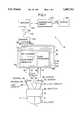
- FIG. 1is a block diagram of a system embodying the invention
- FIG. 2is a plan view of the image plane of the fisheye lens showing a distorted fisheye image
- FIG. 2Ais a diagram of a selected part of the fisheye image, corrected using the present invention.
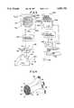
- FIG. 3is a perspective view of the image splitter of the invention.
- FIG. 4is a perspective view of the fiber optic bundles in the image splitter
- FIG. 5is a block diagram of the fisheye distortion correction system of the invention.
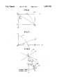
- FIG. 6is a diagram showing the projection of a point C at tilt angle b on the Y axis of the image plane as a result of the fisheye distortion;
- FIG. 7is a diagram of the image plane X-Y showing the projection of a point C on the image plane.
- FIG. 8is a three dimensional diagram showing the primary axis of the fisheye lens, the primary axis of a hypothetical camera panned and tilted to point at point C.
- system 10is provided with a lens 20 which has a substantially hemispherical field of view, for example a fisheye lens. It is preferable to have an azimuthal view of 180°, a zenithal view of 90° and an infinite depth of field. This produces the desired substantially hemispherical field.
- the preferred lensis a commercially available equidistant fisheye lens having a focal length of 1.9 mm, and an f stop of 1.8.
- Lens 20has a primary axis Z and forms a circular image 14 on image plane 13.
- image 14is distorted. Specifically, the orientation of objects in image 14 is altered relative to their real orientation. For example, an object 11 in the field of view of lens 20 (See FIG. 8) will appear on the periphery of image 14 in distorted form as shown in FIG. 2.
- Image 14is preferably split into four separate components by splitter 30.
- Image 14could be split into any number of components, depending on the resolution required and the available technology.
- each componentrespectively contains an image 15, 16, 17 or 18 made up of one quadrant of circular image 14. (See FIG. 2).
- Splitter 30is made up of four light conduits 25, 26, 27 and 28.
- Light conduits 25, 26, 27 and 28respectively contain coherent fiber optic bundles 35, 36, 37 and 38 (See FIG. 4). Images 15, 16, 17 and 18 are thus respectively carried in conduits 25, 26, 27 and 28 by fiber optic bundles 35, 36, 37 and 38.
- Splitter 30is shown in greater detail in FIGS. 3 and 4.
- Splitter 30is made up of a housing 32 to which are attached conduits 25, 26, 27 and 28.
- Optical fiber bundles 35, 36, 37 and 38housed in conduits 25, 26, 27 and 28 respectively, branch off from a major bundle of fibers, terminating at image plane 13 in a polished surface. See FIG. 4.
- Optical fiber bundles 35, 36, 37 and 38are each made up of a plurality of optical fibers. Each optical fiber carries a sample of image 14 formed by fisheye lens 20 and has a diameter of approximately 10 ⁇ m.
- Images 15, 16, 17 and 18respectively travel along each of conduits 25, 26, 27 and 28 and impinge respectively upon sensors 45, 46, 47 and 48.
- Sensors 45, 46, 47 and 48are 768 ⁇ 480 CCD's with fiberoptic windows formed from a fiberoptic faceplate which allows for direct coupling of the CCD's to the optical fibers. Suitable fiberoptic faceplates are available from Galileo Electrooptics Corporation of Sturbridge, Mass. under the name "CP Series.” Images 15, 16, 17 and 18 are respectively converted by the sensors into representative electrical signals 55, 56, 57 and 58.
- CCD control processor 60which is made up four identical off the shelf video camera sensor image controllers 65, 66, 67 and 68, each corresponding respectively to one of signals 55, 56, 57 or 58.
- Each of the control processorscontains a CCD clocking circuit 72, a video processing circuit 74 and a color space converter 76.
- Color space conversion circuit 76produces chrominance and luminance signals Cr, Cb and Y for each signal 55, 56, 57 and 58.
- Control processors 65, 66, 67 and 68respectively produce video outputs 85, 86, 87 and 88 in the form of luminance and chrominance components suitable for compression by encoder 100. Compression of the video signals 85, 86, 87 and 88 allows a very large number of image samples to be transmitted over a channel having limited bandwidth. The video outputs are therefore compressed if the lens is at a location remote from correction circuit 140. Encoder 100 compresses the video signals 85, 86, 87 and 88 by compressing them in accordance with a compression scheme, for example, MPEG or H. 261. Alternatively, a sub-band coding scheme can be used.
- a compression schemefor example, MPEG or H. 261. Alternatively, a sub-band coding scheme can be used.
- Encoder 100packetizes the video signals into a serial data stream for transmission over high speed network 110 such as coaxial cable or optical fibers.
- the compressed video signalsare received by decoder 120 which performs a transform on the compressed video signals which is the inverse of the transform performed by encoder 100.
- Decoder 120produces a decoded video signal 130 which is fed into correction circuit 140.
- correction circuit 140is to correct the distortion introduced by fisheye lens 20. This correction is performed in accordance with the algorithm described below.
- Correction circuit 140produces a corrected signal 150 which is displayed on display 160.
- CCD 180has axes X and Y.
- Lens 20is mounted at a mounting point 17 vertically above surveillance plane 19, preferably such that principal axis Z is perpendicular to surveillance plane 19.
- Surveillance plane 19is the floor of a room 15.
- Mounting point 17is on the ceiling of room 15.
- Axes X, Y and Zintersect at center point I on the surface of CCD 180.
- the surface of CCD 180forms image plane 13 which is parallel to surveillance plane 19.
- the field of viewcovers a full 360°. This allows the simulation of a pan through 360° rather than a pan range limited by the presence of the wall.
- the hypothetical (simulated) pan axisis the primary axis Z of the fisheye lens, rather than an axis perpendicular to the primary axis in the case of a wall mounted lens.
- the angle about the primary axis Zis maintained from the object to the image. This facilitates the calculation of radial coordinates because the pan axis is already in radial form and no conversion is needed.
- the imageis spread over 2R pixels.
- the imageis spread over ⁇ R (half the circumference)-- ⁇ /2 more pixels than for objects appearing at the center of the image.
- Fisheye lens 20has a 180 degree field of view covering area "A.” With lens 20 is mounted on the ceiling of room 15, area A includes the floor and walls of the room. Fisheye lens 20 forms a fisheye image A d of area A on image plane 13. Any point in area A represented by unique coordinates (x;y), is displaced to point (x d ;y d ) in the fisheye image A d in accordance with the characteristics of fisheye lens 20.
- Image plane 13(the surface of CCD 180) is made up of a matrix comprising a plurality of pixels 182. Each pixel has unique fisheye coordinates. CCD thus produces an electronic representation of area A.
- CCD control processor 250identical to control processor 60 which produces chrominance and luminance values for each pixel in CCD 180.
- Those chrominance and luminance valuesare stored in dual ported image memory ("DPIM") 200.
- DPIMdual ported image memory
- the present inventionallows the user to manipulate the fisheye image electronically in order to implement the operations of panning, tilting and zooming.
- a sub-area ⁇ of area Acan be examined in detail by the transformation of sub-area ⁇ d of area A d from a distorted fisheye image into a normal image.
- a default corrected sub-area ⁇ cappears on monitor 240.
- the userselects sub-area ⁇ by means of area select unit 210--a control station having a keyboard and a pointing device. This is done by using pointing device 214 to simulate the panning and a tilting of a hypothetical conventional camera.
- the image on monitor 240appears to have been formed by a conventional camera. In reality, it is formed by correction of part of fisheye image 14.
- the selection of sub-area ⁇provides the normal (non-fisheye) coordinates of an object in the center of sub-area ⁇ . This operation simulates the pointing of the primary axis (IC in FIG. 8) of hypothetical conventional camera at the object.
- the hypothetical camerais mounted at mounting point 17 with its primary axis IC passing through center point I and through the center of sub-area ⁇ . Pointing this hypothetical camera by means of input device 214 such that a sub-area ⁇ appears on monitor 240 also causes area select unit 210 to generate the pan and tilt angles which would be associated with the hypothetical camera positioned at hypothetical pan and tilt angles so that it points at an object in sub-area ⁇ .
- ⁇ dthe distorted fisheye image of area ⁇
- ⁇ cthe corrected image
- Each of the pixels in the fisheye image A dis stored at a unique address in DPIM 200 in the form of the intensity and color data generated by CCD 180 via control processor 250.
- DPIM 200thus contains a digital electronic representation of the distorted fisheye image A d of area A.
- DPIM 200contains an electronic representation of the corresponding distorted sub-area ⁇ d .
- Image plane 13is the plane formed by the X and Y axes as shown in FIGS. 6, 7 and 8.
- Primary axis Z of lens 20is perpendicular to the X and Y axes. If a user wished to view in detail the scene centered around point C (i.e sub-area ⁇ --the image shown in FIG. 2) with a hypothetical non-fisheye lensed camera, the user would instruct the camera to tilt by an angle b relative to the primary axis Z. Doing so would orient the hypothetical camera such that the hypothetical primary axis (center line IC) passes through the center point I of image plane 13 and through point C.
- area ⁇would appear on CCD 180 as an image 300 centered at line 320 and made up of a large number of horizontal lines of pixels 310. (See FIG. 2). Each pixel on a particular horizontal line is displaced from center line 320 by a particular distance x. That distance corresponds to an angle "a" relative to center line IC (See FIG. 8) or angle a' about primary axis Z.
- Each pixel in image 14can be described by reference to a set of rectangular or polar coordinates.
- the pixel at point C on center line ICcan be located by reference to polar coordinates in the form of tilt angle b (See FIG. 6) and angle a--the displacement of the pixel from center (for point C, a is equal to zero since C lies on the X axis).
- tilt angle bSee FIG. 6
- angle a--the displacement of the pixel from centerfor point C, a is equal to zero since C lies on the X axis.
- moving along a horizontal line in CCD 180i.e., moving parallel to the Y axis
- a pixel at point Scan be described by reference to tilt angle b' relative to principle axis Z and pan angle a' relative to center line IC.
- the corresponding rectangular coordinatesare x d and y d .
- the fisheye imageis distorted.
- Objects located close to the principal axis of fisheye lens 20appear on CCD 180 substantially normally (See area 182), whereas, objects further from the principal axis are progressively more distorted (See area 184).
- the information carried by a pixel located at point (x;y) in a non-fisheye imagewill, in the fisheye image, be located at (x d ;y d ), where (x d ;y d ) are displaced from (x;y) by an amount dependent on the properties of fisheye lens 20.
- fis a lens constant in mm/radian indicative of the distortion caused by the fisheye lens
- b'is the angle of an incident ray from an object to the primary axis (in radians).
- the relationship between tilt angle b and the radius at which the image of point C formsis:
- point Clies in the plane formed by the Y and Z axes and at a tilt angle of b relative to the primary axis Z.
- the line IC from the center I of the image plane to point Cis taken as the primary axis of a hypothetical camera lens pointed at point C.
- Line CSextends from point C to a point S.
- CSis parallel to the X axis.
- CSthus represents a horizontal line of pixels in CCD 180.
- Equations (2) and (3)convert the polar coordinates of any particular pixel of the fisheye image formed on CCD to rectangular coordinates.
- the pixel at point Scan therefore be located by reference to tilt angle b' (an angle measured off the principal axis Z) and pan angle a' (the angle of rotation around the principal axis Z).
- a default area ⁇is displayed, corresponding to the initial area at which the hypothetical camera is pointing. For convenience, this area lies along the primary axis Z (so the tilt angle b is zero).
- the pan angleis also zero (i.e., line IC lies along the X axis).
- the hypothetical camera(with the primary axis of its lens lying along line IC) is then tilted by an angle of "b" relative to the primary axis Z of the fisheye lens so that it points at an object centered at point C.
- the panning and tilting of the hypothetical camerais measured relative to the initial position of the hypothetical camera.
- the position of a pixel representing a point at Swill be expressed in terms of tilt angle "b" and the angle of point S from center line IC--angle "a” the amount of pan from center line IC to point S.
- the rectangular coordinates (X;Y) of each pixel in each line of pixels in sub-area ⁇are generated by area select unit 210 and stored in look-up table ("LUT") 222.
- the systemalso automatically calculates the coordinates (X d ;Y d ) of the fisheye image from the using equations (9) and (10). For each set of normal coordinates (X;Y) in sub-area ⁇ , the calculated coordinates (X d ;Y d ) are stored in LUT 222 as addresses in DPIM 200.
- All of the coordinates for the fisheye imagecould be pre-calculated or only the coordinates for a particular area need be calculated as the area is selected. In either case, the coordinates are stored in LUT 222 and the corresponding pixels are stored in DPIM 200. This allows the pixels corresponding to those calculated coordinates to be fetched from CCD 180. The fetched pixels are then displayed on monitor 240 at locations (X;Y) just as if the image had been formed by the panning and tilting of a normal camera to coordinates (X;Y).
- Zoomingcan be accommodated by varying the amount that angle a is incremented between pixels and the amount b is incremented between rows when calculating the contents of LUT 222. For example, if there are 400 pixels on a horizontal display line and a is incremented from -20° for the left side of the display in steps of 0.1°, a 40° horizontal field of view will result. Likewise, to display a 30° vertical field of view that would correctly maintain the 4:3 aspect ratio of a standard display, the 483 display lines would be obtained by incrementing b by 0.062° between each horizontal display line.
- LUT 222 and DPIM 200are represented in the following table:
- a historical log of images over timecan also be stored.
- the oldest imageis continually overwritten with the current image as the memory capacity is exceeded, thus maintaining a revolving log of images generated over a predetermined time period.
- images captured in the preceding predetermined time intervalcan be displayed when an alarm event occurs (e.g. an intruder attempting to enter the monitored premises and triggering a sensor).
- this systemimplements the operations of panning and tilting without any moving parts. This increases the reliability of the camera while limiting the cost of acquiring and maintaining it.
- the inventionthus enables the monitoring of a large area by means of a single camera covering a wide field of view.
Landscapes
- Engineering & Computer Science (AREA)
- Physics & Mathematics (AREA)
- General Physics & Mathematics (AREA)
- Multimedia (AREA)
- Signal Processing (AREA)
- Theoretical Computer Science (AREA)
- Closed-Circuit Television Systems (AREA)
- Studio Devices (AREA)
- Vehicle Body Suspensions (AREA)
- General Factory Administration (AREA)
Abstract
Description
r=f.b (1)
X=f.b'.cos(a') (2)
Y=f.b'.sin(a') (3)
______________________________________ tan(a') = SC/PC SC = IS · sin(a) PC = IC · sin(b) IC = IS · cos(a) therefore tan(a') = IS · sin(a)/IS · cos(a) · sin(b) = tan(a)/sin(b) a' = tan.sup.-1 (tan(a)/sin(b)) (4) cos(b') = IP/IS IP = IC · cos(b) IC = IS · cos(a) therefore cos(b') = IS · cos(a) · cos(b)/IS = cos(a) · cos(b) b' = cos.sup.-1 (cos(a) · cos(b)) (5) ______________________________________
X.sub.d =f.cos.sup.-1 (cos(a).cos(b)).cos(tan.sup.-1 (tan(a)/sin(b))) (6)
Y.sub.d =f.cos.sup.-1 (cos(a).cos(b)).sin(tan.sup.-1 (tan(a)/sin(b))) (7)
a"=p+tan.sup.-1 (tan(a)/sin(b)) (8)
X.sub.d =f.cos.sup.-1 (cos(a).cos(b)).cos(p+tan.sup.-1 (tan(a)/sin(b)) (9)
Y.sub.d =f.cos.sup.-1 (cos(a).cos(b)).sin(p+tan.sup.-1 (tan(a)/sin(b)) (10)
TABLE I ______________________________________ ADDRESS SEQUENCE DUAL FOR BOTH DATA FEA GENERATOR LUT PORT MEMORY STRUCTURES CONTENTS CONTENTS ______________________________________ Starting Address Address of 1st pixel of 1st 1st pixel 1st row row Starting Address + 1 Add. of 2nd pixel of 1st row 2nd pixel 1st row . . . . . . . . . Starting Address + H Add. of 1st pixel of 2nd row 1st pixel 2nd row Starting Address + Add. of 2nd pixel of 2nd row 2nd pixel 2nd row H + 1 . . . . . . . . . Starting Address + 2H Add. of 1st pixel of 3rd row 1st pixel 3rd row Starting Address + Add. of 2nd pixel of 3rd row 2nd pixel 2H + 1 3rd row . . . . . . . . . ______________________________________ H = Number of pixels per line in display processor.
Claims (11)
X.sub.d =f.cos.sup.-1 (cos(a).cos(b)).cos(tan.sup.-1 (tan(a)/sin(b)))
Y.sub.d =f.cos.sup.-1 (cos(a).cos(b)).sin(tan.sup.-1 (tan(a)/sin(b))),
Priority Applications (9)
| Application Number | Priority Date | Filing Date | Title |
|---|---|---|---|
| US08/508,115US5691765A (en) | 1995-07-27 | 1995-07-27 | Image forming and processing device and method for use with no moving parts camera |
| JP50779397AJP3951191B2 (en) | 1995-07-27 | 1996-07-26 | Image forming and processing apparatus and method using camera without moving parts |
| CN96195844ACN1192312A (en) | 1995-07-27 | 1996-07-26 | Image forming and processing device and method for use with no moving parts camera |
| ARP960103756AAR003044A1 (en) | 1995-07-27 | 1996-07-26 | A method of video surveillance. |
| AU66020/96AAU706467B2 (en) | 1995-07-27 | 1996-07-26 | Image forming and processing device and method for use with no moving parts camera |
| EP96925535AEP0842580A4 (en) | 1995-07-27 | 1996-07-26 | Image forming and processing device and method for use with no moving parts camera |
| PCT/US1996/012332WO1997005741A1 (en) | 1995-07-27 | 1996-07-26 | Image forming and processing device and method for use with no moving parts camera |
| CA002220960ACA2220960A1 (en) | 1995-07-27 | 1996-07-26 | Image forming and processing device and method for use with no moving parts camera |
| BR9609894ABR9609894A (en) | 1995-07-27 | 1996-07-26 | Imaging and processing device and method for use with a camera without moving parts |
Applications Claiming Priority (1)
| Application Number | Priority Date | Filing Date | Title |
|---|---|---|---|
| US08/508,115US5691765A (en) | 1995-07-27 | 1995-07-27 | Image forming and processing device and method for use with no moving parts camera |
Publications (1)
| Publication Number | Publication Date |
|---|---|
| US5691765Atrue US5691765A (en) | 1997-11-25 |
Family
ID=24021448
Family Applications (1)
| Application Number | Title | Priority Date | Filing Date |
|---|---|---|---|
| US08/508,115Expired - LifetimeUS5691765A (en) | 1995-07-27 | 1995-07-27 | Image forming and processing device and method for use with no moving parts camera |
Country Status (9)
| Country | Link |
|---|---|
| US (1) | US5691765A (en) |
| EP (1) | EP0842580A4 (en) |
| JP (1) | JP3951191B2 (en) |
| CN (1) | CN1192312A (en) |
| AR (1) | AR003044A1 (en) |
| AU (1) | AU706467B2 (en) |
| BR (1) | BR9609894A (en) |
| CA (1) | CA2220960A1 (en) |
| WO (1) | WO1997005741A1 (en) |
Cited By (42)
| Publication number | Priority date | Publication date | Assignee | Title |
|---|---|---|---|---|
| US5832139A (en)* | 1996-07-31 | 1998-11-03 | Omniplanar, Inc. | Method and apparatus for determining degrees of freedom of a camera |
| US5856844A (en)* | 1995-09-21 | 1999-01-05 | Omniplanar, Inc. | Method and apparatus for determining position and orientation |
| EP0933666A1 (en)* | 1998-01-30 | 1999-08-04 | SONY DEUTSCHLAND GmbH | Image detecting apparatus controlled by detecting the viewing direction |
| WO1999065245A1 (en)* | 1998-06-11 | 1999-12-16 | Surreal Online Pte Ltd. | A method and system for providing a seamless omniview image from fisheye images |
| EP0927979A3 (en)* | 1997-12-29 | 2000-06-28 | François Dipl.-Ing. Sodji | Device for monitoring a building and/or a room |
| WO2000060869A1 (en)* | 1999-04-08 | 2000-10-12 | Internet Pictures Corporation | Perspective-corrected video presentations |
| US6204852B1 (en)* | 1998-12-09 | 2001-03-20 | Lucent Technologies Inc. | Video hand image three-dimensional computer interface |
| US20010015751A1 (en)* | 1998-06-16 | 2001-08-23 | Genex Technologies, Inc. | Method and apparatus for omnidirectional imaging |
| US20020061134A1 (en)* | 2000-11-17 | 2002-05-23 | Honeywell International Inc. | Object detection |
| US20020125435A1 (en)* | 2001-01-19 | 2002-09-12 | Cofer Darren D. | Method and apparatus for detecting objects |
| US20030164877A1 (en)* | 2000-06-30 | 2003-09-04 | Nobuo Murai | Remote monitoring method and monitor control server |
| US20040146184A1 (en)* | 2000-11-17 | 2004-07-29 | Hamza Ridha M | Object detection |
| US6778211B1 (en) | 1999-04-08 | 2004-08-17 | Ipix Corp. | Method and apparatus for providing virtual processing effects for wide-angle video images |
| US20040202380A1 (en)* | 2001-03-05 | 2004-10-14 | Thorsten Kohler | Method and device for correcting an image, particularly for occupant protection |
| US20040256541A1 (en)* | 2001-01-19 | 2004-12-23 | Honeywell International Inc. | Method and apparatus for detecting objects using structured light patterns |
| US20050007478A1 (en)* | 2003-05-02 | 2005-01-13 | Yavuz Ahiska | Multiple-view processing in wide-angle video camera |
| US20060034370A1 (en)* | 2004-08-13 | 2006-02-16 | Samsung Electronics Co., Ltd. | Method and apparatus for interpolating a reference pixel in an annular image and encoding/decoding an annular image |
| US7015954B1 (en) | 1999-08-09 | 2006-03-21 | Fuji Xerox Co., Ltd. | Automatic video system using multiple cameras |
| US20070002159A1 (en)* | 2005-07-01 | 2007-01-04 | Olsen Richard I | Method and apparatus for use in camera and systems employing same |
| US20070071349A1 (en)* | 2005-09-27 | 2007-03-29 | Primax Electronics Ltd. | Focus adjustable method of optical image |
| US20070177819A1 (en)* | 2006-02-01 | 2007-08-02 | Honeywell International Inc. | Multi-spectral fusion for video surveillance |
| US20070211164A1 (en)* | 2004-08-25 | 2007-09-13 | Olsen Richard I | Imager module optical focus and assembly method |
| US20070258006A1 (en)* | 2005-08-25 | 2007-11-08 | Olsen Richard I | Solid state camera optics frame and assembly |
| US20070295893A1 (en)* | 2004-08-25 | 2007-12-27 | Olsen Richard I | Lens frame and optical focus assembly for imager module |
| US20080030597A1 (en)* | 2004-08-25 | 2008-02-07 | Newport Imaging Corporation | Digital camera with multiple pipeline signal processors |
| US20080174670A1 (en)* | 2004-08-25 | 2008-07-24 | Richard Ian Olsen | Simultaneous multiple field of view digital cameras |
| CN100465783C (en)* | 2005-10-09 | 2009-03-04 | 致伸科技股份有限公司 | Focusing adjustment method of optical lens module |
| US20090268043A1 (en)* | 2004-08-25 | 2009-10-29 | Richard Ian Olsen | Large dynamic range cameras |
| DE102008062997A1 (en)* | 2008-12-23 | 2010-07-22 | Mobotix Ag | bus camera |
| US20100194850A1 (en)* | 2009-01-30 | 2010-08-05 | Panasonic Automotive Systems Company Of America, Division Of Panasonic Corporation Of North America | Method and apparatus for correction of an image from a fisheye lens in a camera |
| US20100201833A1 (en)* | 2007-07-20 | 2010-08-12 | Techwell Japan K.K. | Image Processing Apparatus and Camera System |
| US20110059341A1 (en)* | 2008-06-12 | 2011-03-10 | Junichi Matsumoto | Electric vehicle |
| US7964835B2 (en) | 2005-08-25 | 2011-06-21 | Protarius Filo Ag, L.L.C. | Digital cameras with direct luminance and chrominance detection |
| US20120098965A1 (en)* | 2010-10-21 | 2012-04-26 | Sensormatic Electronics, LLC | Method and system for converting privacy zone planar images to their corresponding pan/tilt coordinates |
| US20120242788A1 (en)* | 2010-12-16 | 2012-09-27 | The Massachusetts Institute Of Technology | Imaging system for immersive surveillance |
| US8405731B2 (en) | 2007-02-19 | 2013-03-26 | Axis Ab | Method for compensating hardware misalignments in a camera |
| ES2545542A1 (en)* | 2014-03-11 | 2015-09-11 | Alberto ADARVE LOZANO | Panoramic vision system with image correction in refueling operations and the like |
| US10178314B2 (en) | 2011-03-08 | 2019-01-08 | Mitsubishi Electric Corporation | Moving object periphery image correction apparatus |
| CN112150554A (en)* | 2019-06-28 | 2020-12-29 | 杭州海康威视数字技术股份有限公司 | Picture display method, device, terminal and storage medium |
| US11032481B2 (en) | 2018-07-06 | 2021-06-08 | Medos International Sarl | Camera scope electronic variable prism |
| US11202014B2 (en) | 2018-07-06 | 2021-12-14 | Medos International Sari | Camera scope electronic variable angle of view |
| WO2024249970A1 (en)* | 2023-06-02 | 2024-12-05 | Apple Inc. | Virtual camera rendering for user framing adjustments |
Families Citing this family (13)
| Publication number | Priority date | Publication date | Assignee | Title |
|---|---|---|---|---|
| AU1901701A (en)* | 1999-11-15 | 2001-05-30 | Equal Reverse Thoughts Limited | Method of improved image depth perception |
| GB2368221A (en)* | 2000-08-31 | 2002-04-24 | Lee Scott Friend | Camera apparatus having both omnidirectional and normal view imaging modes. |
| JP2005339313A (en) | 2004-05-28 | 2005-12-08 | Toshiba Corp | Image presentation method and apparatus |
| JP2007318597A (en)* | 2006-05-29 | 2007-12-06 | Opt Kk | Compression method of image data by wide angle lens, compression apparatus, wide angle camera apparatus, and monitor system |
| JP2007318596A (en)* | 2006-05-29 | 2007-12-06 | Opt Kk | Compression method of image data by wide angle lens, expansion display method, compression apparatus, wide angle camera apparatus, and monitor system |
| JP4977419B2 (en) | 2006-08-10 | 2012-07-18 | 三洋電機株式会社 | Surveillance camera |
| CN101188741B (en)* | 2006-11-16 | 2010-08-18 | 中兴通讯股份有限公司 | A monitoring control system |
| KR101014572B1 (en)* | 2007-08-27 | 2011-02-16 | 주식회사 코아로직 | Image distortion correction method and image processing apparatus employing the correction method |
| JP5499802B2 (en)* | 2010-03-18 | 2014-05-21 | 株式会社デンソーウェーブ | Visual inspection system |
| TWI476730B (en)* | 2012-10-31 | 2015-03-11 | Vivotek Inc | A de-warp method of the digital image |
| KR101465607B1 (en)* | 2012-12-05 | 2014-11-27 | 광운대학교 산학협력단 | Distorted Image Processing Method For Fish-Eye Lens |
| EP3051495B1 (en)* | 2015-01-29 | 2018-09-19 | Wipro Limited | Systems and methods for mapping object coordinates from a video frame view to real world coordinates |
| US9792664B2 (en) | 2015-01-29 | 2017-10-17 | Wipro Limited | System and method for mapping object coordinates from a video to real world coordinates using perspective transformation |
Citations (6)
| Publication number | Priority date | Publication date | Assignee | Title |
|---|---|---|---|---|
| US4984089A (en)* | 1990-01-08 | 1991-01-08 | Sensormatic Electronics Corporation | Outdoor surveillance dome with enhanced environmental aptitude and control system therefor |
| US5185667A (en)* | 1991-05-13 | 1993-02-09 | Telerobotics International, Inc. | Omniview motionless camera orientation system |
| US5200818A (en)* | 1991-03-22 | 1993-04-06 | Inbal Neta | Video imaging system with interactive windowing capability |
| US5319744A (en)* | 1991-04-03 | 1994-06-07 | General Electric Company | Polygon fragmentation method of distortion correction in computer image generating systems |
| US5359363A (en)* | 1991-05-13 | 1994-10-25 | Telerobotics International, Inc. | Omniview motionless camera surveillance system |
| US5586231A (en)* | 1993-12-29 | 1996-12-17 | U.S. Philips Corporation | Method and device for processing an image in order to construct from a source image a target image with charge of perspective |
Family Cites Families (4)
| Publication number | Priority date | Publication date | Assignee | Title |
|---|---|---|---|---|
| JPS59184973A (en)* | 1983-04-04 | 1984-10-20 | Fujitsu Ltd | Environment understanding system of robot |
| JPS60205381A (en)* | 1984-03-30 | 1985-10-16 | Fuji Electric Corp Res & Dev Ltd | Omnidirectional position detector |
| US5384588A (en)* | 1991-05-13 | 1995-01-24 | Telerobotics International, Inc. | System for omindirectional image viewing at a remote location without the transmission of control signals to select viewing parameters |
| JPH0636020A (en)* | 1992-07-17 | 1994-02-10 | Matsushita Electric Ind Co Ltd | Image pickup monitoring device |
- 1995
- 1995-07-27USUS08/508,115patent/US5691765A/ennot_activeExpired - Lifetime
- 1996
- 1996-07-26CNCN96195844Apatent/CN1192312A/enactivePending
- 1996-07-26EPEP96925535Apatent/EP0842580A4/ennot_activeWithdrawn
- 1996-07-26WOPCT/US1996/012332patent/WO1997005741A1/ennot_activeApplication Discontinuation
- 1996-07-26JPJP50779397Apatent/JP3951191B2/ennot_activeExpired - Lifetime
- 1996-07-26AUAU66020/96Apatent/AU706467B2/ennot_activeCeased
- 1996-07-26ARARP960103756Apatent/AR003044A1/enunknown
- 1996-07-26CACA002220960Apatent/CA2220960A1/ennot_activeAbandoned
- 1996-07-26BRBR9609894Apatent/BR9609894A/ennot_activeApplication Discontinuation
Patent Citations (6)
| Publication number | Priority date | Publication date | Assignee | Title |
|---|---|---|---|---|
| US4984089A (en)* | 1990-01-08 | 1991-01-08 | Sensormatic Electronics Corporation | Outdoor surveillance dome with enhanced environmental aptitude and control system therefor |
| US5200818A (en)* | 1991-03-22 | 1993-04-06 | Inbal Neta | Video imaging system with interactive windowing capability |
| US5319744A (en)* | 1991-04-03 | 1994-06-07 | General Electric Company | Polygon fragmentation method of distortion correction in computer image generating systems |
| US5185667A (en)* | 1991-05-13 | 1993-02-09 | Telerobotics International, Inc. | Omniview motionless camera orientation system |
| US5359363A (en)* | 1991-05-13 | 1994-10-25 | Telerobotics International, Inc. | Omniview motionless camera surveillance system |
| US5586231A (en)* | 1993-12-29 | 1996-12-17 | U.S. Philips Corporation | Method and device for processing an image in order to construct from a source image a target image with charge of perspective |
Non-Patent Citations (5)
| Title |
|---|
| "Near-Fisheye CCD Camera Broadens View for Imaging", by Francis Hamit, Advanced Imaging, Mar., 1993. |
| NASA Tech Briefs, Mar., 1994, pp. 46 and 48.* |
| Near Fisheye CCD Camera Broadens View for Imaging , by Francis Hamit, Advanced Imaging, Mar., 1993.* |
| Schott Fiber Optics, "Fused Fiber Optic Tapers", Apr., 1994. |
| Schott Fiber Optics, Fused Fiber Optic Tapers , Apr., 1994.* |
Cited By (102)
| Publication number | Priority date | Publication date | Assignee | Title |
|---|---|---|---|---|
| US5856844A (en)* | 1995-09-21 | 1999-01-05 | Omniplanar, Inc. | Method and apparatus for determining position and orientation |
| US5832139A (en)* | 1996-07-31 | 1998-11-03 | Omniplanar, Inc. | Method and apparatus for determining degrees of freedom of a camera |
| EP0927979A3 (en)* | 1997-12-29 | 2000-06-28 | François Dipl.-Ing. Sodji | Device for monitoring a building and/or a room |
| EP0933666A1 (en)* | 1998-01-30 | 1999-08-04 | SONY DEUTSCHLAND GmbH | Image detecting apparatus controlled by detecting the viewing direction |
| WO1999065245A1 (en)* | 1998-06-11 | 1999-12-16 | Surreal Online Pte Ltd. | A method and system for providing a seamless omniview image from fisheye images |
| US20010015751A1 (en)* | 1998-06-16 | 2001-08-23 | Genex Technologies, Inc. | Method and apparatus for omnidirectional imaging |
| US6204852B1 (en)* | 1998-12-09 | 2001-03-20 | Lucent Technologies Inc. | Video hand image three-dimensional computer interface |
| US6778211B1 (en) | 1999-04-08 | 2004-08-17 | Ipix Corp. | Method and apparatus for providing virtual processing effects for wide-angle video images |
| WO2000060869A1 (en)* | 1999-04-08 | 2000-10-12 | Internet Pictures Corporation | Perspective-corrected video presentations |
| US20050062869A1 (en)* | 1999-04-08 | 2005-03-24 | Zimmermann Steven Dwain | Immersive video presentations |
| US20050007483A1 (en)* | 1999-04-08 | 2005-01-13 | Zimmermann Steven Dwain | Method and apparatus for providing virtual processing effects for wide-angle video images |
| US7312820B2 (en) | 1999-04-08 | 2007-12-25 | Ipix Corporation | Method and apparatus for providing virtual processing effects for wide-angle video images |
| US7277118B2 (en) | 1999-08-09 | 2007-10-02 | Fuji Xerox Co., Ltd. | Method and system for compensating for parallax in multiple camera systems |
| US7710463B2 (en) | 1999-08-09 | 2010-05-04 | Fuji Xerox Co., Ltd. | Method and system for compensating for parallax in multiple camera systems |
| US7015954B1 (en) | 1999-08-09 | 2006-03-21 | Fuji Xerox Co., Ltd. | Automatic video system using multiple cameras |
| US20030164877A1 (en)* | 2000-06-30 | 2003-09-04 | Nobuo Murai | Remote monitoring method and monitor control server |
| US7231654B2 (en)* | 2000-06-30 | 2007-06-12 | Japan Network Service Co., Ltd. | Remote monitoring method and monitor control server |
| US20040146184A1 (en)* | 2000-11-17 | 2004-07-29 | Hamza Ridha M | Object detection |
| US20020061134A1 (en)* | 2000-11-17 | 2002-05-23 | Honeywell International Inc. | Object detection |
| US7200246B2 (en) | 2000-11-17 | 2007-04-03 | Honeywell International Inc. | Object detection |
| US7184585B2 (en) | 2000-11-17 | 2007-02-27 | Honeywell International Inc. | Object detection |
| US20040256541A1 (en)* | 2001-01-19 | 2004-12-23 | Honeywell International Inc. | Method and apparatus for detecting objects using structured light patterns |
| US6841780B2 (en) | 2001-01-19 | 2005-01-11 | Honeywell International Inc. | Method and apparatus for detecting objects |
| US7176440B2 (en) | 2001-01-19 | 2007-02-13 | Honeywell International Inc. | Method and apparatus for detecting objects using structured light patterns |
| US20060038114A9 (en)* | 2001-01-19 | 2006-02-23 | Honeywell International Inc. | Method and apparatus for detecting objects using structured light patterns |
| US20020125435A1 (en)* | 2001-01-19 | 2002-09-12 | Cofer Darren D. | Method and apparatus for detecting objects |
| US20040202380A1 (en)* | 2001-03-05 | 2004-10-14 | Thorsten Kohler | Method and device for correcting an image, particularly for occupant protection |
| US7304680B2 (en)* | 2001-03-05 | 2007-12-04 | Siemens Aktiengesellschaft | Method and device for correcting an image, particularly for occupant protection |
| US7450165B2 (en)* | 2003-05-02 | 2008-11-11 | Grandeye, Ltd. | Multiple-view processing in wide-angle video camera |
| US20050007478A1 (en)* | 2003-05-02 | 2005-01-13 | Yavuz Ahiska | Multiple-view processing in wide-angle video camera |
| US8130827B2 (en)* | 2004-08-13 | 2012-03-06 | Samsung Electronics Co., Ltd. | Method and apparatus for interpolating a reference pixel in an annular image and encoding/decoding an annular image |
| US20060034370A1 (en)* | 2004-08-13 | 2006-02-16 | Samsung Electronics Co., Ltd. | Method and apparatus for interpolating a reference pixel in an annular image and encoding/decoding an annular image |
| US8436286B2 (en) | 2004-08-25 | 2013-05-07 | Protarius Filo Ag, L.L.C. | Imager module optical focus and assembly method |
| US8415605B2 (en) | 2004-08-25 | 2013-04-09 | Protarius Filo Ag, L.L.C. | Digital camera with multiple pipeline signal processors |
| US20070295893A1 (en)* | 2004-08-25 | 2007-12-27 | Olsen Richard I | Lens frame and optical focus assembly for imager module |
| US20080030597A1 (en)* | 2004-08-25 | 2008-02-07 | Newport Imaging Corporation | Digital camera with multiple pipeline signal processors |
| US8664579B2 (en) | 2004-08-25 | 2014-03-04 | Protarius Filo Ag, L.L.C. | Digital camera with multiple pipeline signal processors |
| US20080174670A1 (en)* | 2004-08-25 | 2008-07-24 | Richard Ian Olsen | Simultaneous multiple field of view digital cameras |
| US10142548B2 (en) | 2004-08-25 | 2018-11-27 | Callahan Cellular L.L.C. | Digital camera with multiple pipeline signal processors |
| US8598504B2 (en) | 2004-08-25 | 2013-12-03 | Protarius Filo Ag, L.L.C. | Large dynamic range cameras |
| US20090268043A1 (en)* | 2004-08-25 | 2009-10-29 | Richard Ian Olsen | Large dynamic range cameras |
| US20070211164A1 (en)* | 2004-08-25 | 2007-09-13 | Olsen Richard I | Imager module optical focus and assembly method |
| US20090302205A9 (en)* | 2004-08-25 | 2009-12-10 | Olsen Richard I | Lens frame and optical focus assembly for imager module |
| US7916180B2 (en)* | 2004-08-25 | 2011-03-29 | Protarius Filo Ag, L.L.C. | Simultaneous multiple field of view digital cameras |
| US20100060746A9 (en)* | 2004-08-25 | 2010-03-11 | Richard Ian Olsen | Simultaneous multiple field of view digital cameras |
| US9232158B2 (en) | 2004-08-25 | 2016-01-05 | Callahan Cellular L.L.C. | Large dynamic range cameras |
| US8334494B2 (en) | 2004-08-25 | 2012-12-18 | Protarius Filo Ag, L.L.C. | Large dynamic range cameras |
| US8198574B2 (en) | 2004-08-25 | 2012-06-12 | Protarius Filo Ag, L.L.C. | Large dynamic range cameras |
| US9313393B2 (en) | 2004-08-25 | 2016-04-12 | Callahan Cellular L.L.C. | Digital camera with multiple pipeline signal processors |
| US10009556B2 (en) | 2004-08-25 | 2018-06-26 | Callahan Cellular L.L.C. | Large dynamic range cameras |
| US8124929B2 (en) | 2004-08-25 | 2012-02-28 | Protarius Filo Ag, L.L.C. | Imager module optical focus and assembly method |
| US20100208100A9 (en)* | 2004-08-25 | 2010-08-19 | Newport Imaging Corporation | Digital camera with multiple pipeline signal processors |
| US7795577B2 (en) | 2004-08-25 | 2010-09-14 | Richard Ian Olsen | Lens frame and optical focus assembly for imager module |
| US7884309B2 (en) | 2004-08-25 | 2011-02-08 | Richard Ian Olsen | Digital camera with multiple pipeline signal processors |
| US7772532B2 (en) | 2005-07-01 | 2010-08-10 | Richard Ian Olsen | Camera and method having optics and photo detectors which are adjustable with respect to each other |
| US7714262B2 (en) | 2005-07-01 | 2010-05-11 | Richard Ian Olsen | Digital camera with integrated ultraviolet (UV) response |
| US20070002159A1 (en)* | 2005-07-01 | 2007-01-04 | Olsen Richard I | Method and apparatus for use in camera and systems employing same |
| US20080029708A1 (en)* | 2005-07-01 | 2008-02-07 | Newport Imaging Corporation | Digital camera with integrated ultraviolet (UV) response |
| US8629390B2 (en) | 2005-08-25 | 2014-01-14 | Protarius Filo Ag, L.L.C. | Digital cameras with direct luminance and chrominance detection |
| US9294745B2 (en) | 2005-08-25 | 2016-03-22 | Callahan Cellular L.L.C. | Digital cameras with direct luminance and chrominance detection |
| US10148927B2 (en) | 2005-08-25 | 2018-12-04 | Callahan Cellular L.L.C. | Digital cameras with direct luminance and chrominance detection |
| US7964835B2 (en) | 2005-08-25 | 2011-06-21 | Protarius Filo Ag, L.L.C. | Digital cameras with direct luminance and chrominance detection |
| US12200374B2 (en) | 2005-08-25 | 2025-01-14 | Intellectual Ventures Ii Llc | Digital cameras with direct luminance and chrominance detection |
| US8304709B2 (en) | 2005-08-25 | 2012-11-06 | Protarius Filo Ag, L.L.C. | Digital cameras with direct luminance and chrominance detection |
| US10694162B2 (en) | 2005-08-25 | 2020-06-23 | Callahan Cellular L.L.C. | Digital cameras with direct luminance and chrominance detection |
| US11706535B2 (en) | 2005-08-25 | 2023-07-18 | Intellectual Ventures Ii Llc | Digital cameras with direct luminance and chrominance detection |
| US20070258006A1 (en)* | 2005-08-25 | 2007-11-08 | Olsen Richard I | Solid state camera optics frame and assembly |
| US11425349B2 (en) | 2005-08-25 | 2022-08-23 | Intellectual Ventures Ii Llc | Digital cameras with direct luminance and chrominance detection |
| US20110205407A1 (en)* | 2005-08-25 | 2011-08-25 | Richard Ian Olsen | Digital cameras with direct luminance and chrominance detection |
| US11412196B2 (en) | 2005-08-25 | 2022-08-09 | Intellectual Ventures Ii Llc | Digital cameras with direct luminance and chrominance detection |
| US7634183B2 (en)* | 2005-09-27 | 2009-12-15 | Primax Electronics Ltd. | Focus adjustable method of optical image |
| US20070071349A1 (en)* | 2005-09-27 | 2007-03-29 | Primax Electronics Ltd. | Focus adjustable method of optical image |
| CN100465783C (en)* | 2005-10-09 | 2009-03-04 | 致伸科技股份有限公司 | Focusing adjustment method of optical lens module |
| US20070177819A1 (en)* | 2006-02-01 | 2007-08-02 | Honeywell International Inc. | Multi-spectral fusion for video surveillance |
| US7613360B2 (en) | 2006-02-01 | 2009-11-03 | Honeywell International Inc | Multi-spectral fusion for video surveillance |
| US8405731B2 (en) | 2007-02-19 | 2013-03-26 | Axis Ab | Method for compensating hardware misalignments in a camera |
| US9118831B2 (en)* | 2007-07-20 | 2015-08-25 | Intersil Americas LLC | Image processing apparatus and camera system |
| US20130222532A1 (en)* | 2007-07-20 | 2013-08-29 | Intersil Corporation | Image Processing Apparatus and Camera System |
| US20100201833A1 (en)* | 2007-07-20 | 2010-08-12 | Techwell Japan K.K. | Image Processing Apparatus and Camera System |
| US8325247B2 (en)* | 2007-07-20 | 2012-12-04 | Techwell Japan K.K. | Image processing apparatus and camera system |
| US20110059341A1 (en)* | 2008-06-12 | 2011-03-10 | Junichi Matsumoto | Electric vehicle |
| US9165445B2 (en) | 2008-12-23 | 2015-10-20 | Mobotix Ag | Omnibus camera |
| DE102008062997A1 (en)* | 2008-12-23 | 2010-07-22 | Mobotix Ag | bus camera |
| US8988492B2 (en)* | 2009-01-30 | 2015-03-24 | Panasonic Automotive Systems Company Of America, Division Of Panasonic Corporation Of North America | Method and apparatus for correction of an image from a fisheye lens in a camera |
| US20100194850A1 (en)* | 2009-01-30 | 2010-08-05 | Panasonic Automotive Systems Company Of America, Division Of Panasonic Corporation Of North America | Method and apparatus for correction of an image from a fisheye lens in a camera |
| US9794518B2 (en)* | 2010-10-21 | 2017-10-17 | Sensormatic Electronics, LLC | Method and system for converting privacy zone planar images to their corresponding pan/tilt coordinates |
| US20120098965A1 (en)* | 2010-10-21 | 2012-04-26 | Sensormatic Electronics, LLC | Method and system for converting privacy zone planar images to their corresponding pan/tilt coordinates |
| US10630899B2 (en) | 2010-12-16 | 2020-04-21 | Massachusetts Institute Of Technology | Imaging system for immersive surveillance |
| US9749526B2 (en) | 2010-12-16 | 2017-08-29 | Massachusetts Institute Of Technology | Imaging system for immersive surveillance |
| US20120242788A1 (en)* | 2010-12-16 | 2012-09-27 | The Massachusetts Institute Of Technology | Imaging system for immersive surveillance |
| US9036001B2 (en)* | 2010-12-16 | 2015-05-19 | Massachusetts Institute Of Technology | Imaging system for immersive surveillance |
| US10178314B2 (en) | 2011-03-08 | 2019-01-08 | Mitsubishi Electric Corporation | Moving object periphery image correction apparatus |
| WO2015136138A1 (en)* | 2014-03-11 | 2015-09-17 | Alberto Adarve Lozano | Panoramic viewing system with image correction in refuelling and similar operations |
| ES2545542A1 (en)* | 2014-03-11 | 2015-09-11 | Alberto ADARVE LOZANO | Panoramic vision system with image correction in refueling operations and the like |
| US11032481B2 (en) | 2018-07-06 | 2021-06-08 | Medos International Sarl | Camera scope electronic variable prism |
| US11317029B2 (en) | 2018-07-06 | 2022-04-26 | Medos International Sarl | Camera scope electronic variable prism |
| US11202014B2 (en) | 2018-07-06 | 2021-12-14 | Medos International Sari | Camera scope electronic variable angle of view |
| US12082772B2 (en) | 2018-07-06 | 2024-09-10 | Medos International Sarl | Camera scope electronic variable prism |
| US12200364B2 (en) | 2018-07-06 | 2025-01-14 | Medos International Sarl | Camera scope electronic variable prism |
| CN112150554B (en)* | 2019-06-28 | 2023-08-04 | 杭州海康威视数字技术股份有限公司 | Picture display method, device, terminal and storage medium |
| CN112150554A (en)* | 2019-06-28 | 2020-12-29 | 杭州海康威视数字技术股份有限公司 | Picture display method, device, terminal and storage medium |
| WO2024249970A1 (en)* | 2023-06-02 | 2024-12-05 | Apple Inc. | Virtual camera rendering for user framing adjustments |
Also Published As
| Publication number | Publication date |
|---|---|
| AU706467B2 (en) | 1999-06-17 |
| CA2220960A1 (en) | 1997-02-13 |
| EP0842580A4 (en) | 2000-08-02 |
| AU6602096A (en) | 1997-02-26 |
| CN1192312A (en) | 1998-09-02 |
| BR9609894A (en) | 1999-05-25 |
| AR003044A1 (en) | 1998-05-27 |
| JPH11510341A (en) | 1999-09-07 |
| JP3951191B2 (en) | 2007-08-01 |
| EP0842580A1 (en) | 1998-05-20 |
| WO1997005741A1 (en) | 1997-02-13 |
Similar Documents
| Publication | Publication Date | Title |
|---|---|---|
| US5691765A (en) | Image forming and processing device and method for use with no moving parts camera | |
| US5870135A (en) | Image splitting forming and processing device and method for use with no moving parts camera | |
| US5686957A (en) | Teleconferencing imaging system with automatic camera steering | |
| US9794518B2 (en) | Method and system for converting privacy zone planar images to their corresponding pan/tilt coordinates | |
| AU701222B2 (en) | Video surveillance system | |
| US6583815B1 (en) | Method and apparatus for presenting images from a remote location | |
| US20110310219A1 (en) | Intelligent monitoring camera apparatus and image monitoring system implementing same | |
| US6043837A (en) | Method and apparatus for electronically distributing images from a panoptic camera system | |
| US6226035B1 (en) | Adjustable imaging system with wide angle capability | |
| US7148914B2 (en) | Method and apparatus for providing subimages to remote sites | |
| US20100045773A1 (en) | Panoramic adapter system and method with spherical field-of-view coverage | |
| US20030103063A1 (en) | Panoramic imaging and display system with canonical magnifier | |
| CA2115179C (en) | System for the monitoring and detection of heat sources in open areas | |
| CA2530187A1 (en) | Panoramic video system with real-time distortion-free imaging | |
| JP2006352851A (en) | Method and device for acquiring image of scene using composite camera | |
| CA1289655C (en) | Portable infrared imaging apparatus | |
| KR100585822B1 (en) | Surveillance system using real-time panoramic video image and control method thereof | |
| JPH11146295A (en) | Image transfer system | |
| JP2001169271A (en) | Image information provision system using 360-degree digital camera | |
| Butterfield | Very high resolution stereoscopic television | |
| GB2360413A (en) | Wide angle parabolic imaging and image mapping apparatus | |
| JP3206766B2 (en) | Remote monitoring device | |
| HK1016000A (en) | Image forming and processing device and method for use with no moving parts camera | |
| HK1015999A (en) | Image splitting, forming and processing device and method for use with no moving parts camera | |
| JPH05183902A (en) | Tv interphone |
Legal Events
| Date | Code | Title | Description |
|---|---|---|---|
| AS | Assignment | Owner name:SENSORMATIC ELECTRONICS CORPORATION, FLORIDA Free format text:ASSIGNMENT OF ASSIGNORS INTEREST;ASSIGNORS:SCHIELTZ, STEVEN W.;LAURANCE, TERRY;KUPERSMIT, CARL;REEL/FRAME:007707/0046 Effective date:19951026 | |
| AS | Assignment | Owner name:SENSORMATIC ELECTRONICS CORPORATION, FLORIDA Free format text:ASSIGNMENT OF ASSIGNORS INTEREST;ASSIGNORS:SCHIELTZ, STEVEN W.;GLATT, TERRY LAURENCE;KUPERSMIT, CARL;REEL/FRAME:007932/0537 Effective date:19960424 | |
| STCF | Information on status: patent grant | Free format text:PATENTED CASE | |
| FEPP | Fee payment procedure | Free format text:PAYOR NUMBER ASSIGNED (ORIGINAL EVENT CODE: ASPN); ENTITY STATUS OF PATENT OWNER: LARGE ENTITY | |
| FPAY | Fee payment | Year of fee payment:4 | |
| AS | Assignment | Owner name:SENSORMATIC ELECTRONICS CORPORATION, FLORIDA Free format text:MERGER/CHANGE OF NAME;ASSIGNOR:SENSORMATIC ELECTRONICS CORPORATION;REEL/FRAME:012991/0641 Effective date:20011113 | |
| FPAY | Fee payment | Year of fee payment:8 | |
| FPAY | Fee payment | Year of fee payment:12 | |
| AS | Assignment | Owner name:SENSORMATIC ELECTRONICS, LLC,FLORIDA Free format text:MERGER;ASSIGNOR:SENSORMATIC ELECTRONICS CORPORATION;REEL/FRAME:024213/0049 Effective date:20090922 Owner name:SENSORMATIC ELECTRONICS, LLC, FLORIDA Free format text:MERGER;ASSIGNOR:SENSORMATIC ELECTRONICS CORPORATION;REEL/FRAME:024213/0049 Effective date:20090922 |