US5691692A - Portable machine with machine diagnosis indicator circuit - Google Patents
Portable machine with machine diagnosis indicator circuitDownload PDFInfo
- Publication number
- US5691692A US5691692AUS08/591,331US59133196AUS5691692AUS 5691692 AUS5691692 AUS 5691692AUS 59133196 AUS59133196 AUS 59133196AUS 5691692 AUS5691692 AUS 5691692A
- Authority
- US
- United States
- Prior art keywords
- machine
- engine
- combination
- protective
- diagnosis
- Prior art date
- Legal status (The legal status is an assumption and is not a legal conclusion. Google has not performed a legal analysis and makes no representation as to the accuracy of the status listed.)
- Expired - Lifetime
Links
Images


Classifications
- F—MECHANICAL ENGINEERING; LIGHTING; HEATING; WEAPONS; BLASTING
- F02—COMBUSTION ENGINES; HOT-GAS OR COMBUSTION-PRODUCT ENGINE PLANTS
- F02B—INTERNAL-COMBUSTION PISTON ENGINES; COMBUSTION ENGINES IN GENERAL
- F02B63/00—Adaptations of engines for driving pumps, hand-held tools or electric generators; Portable combinations of engines with engine-driven devices
- F02B63/06—Adaptations of engines for driving pumps, hand-held tools or electric generators; Portable combinations of engines with engine-driven devices for pumps
- G—PHYSICS
- G07—CHECKING-DEVICES
- G07C—TIME OR ATTENDANCE REGISTERS; REGISTERING OR INDICATING THE WORKING OF MACHINES; GENERATING RANDOM NUMBERS; VOTING OR LOTTERY APPARATUS; ARRANGEMENTS, SYSTEMS OR APPARATUS FOR CHECKING NOT PROVIDED FOR ELSEWHERE
- G07C5/00—Registering or indicating the working of vehicles
- G07C5/08—Registering or indicating performance data other than driving, working, idle, or waiting time, with or without registering driving, working, idle or waiting time
- G07C5/0808—Diagnosing performance data
- G—PHYSICS
- G07—CHECKING-DEVICES
- G07C—TIME OR ATTENDANCE REGISTERS; REGISTERING OR INDICATING THE WORKING OF MACHINES; GENERATING RANDOM NUMBERS; VOTING OR LOTTERY APPARATUS; ARRANGEMENTS, SYSTEMS OR APPARATUS FOR CHECKING NOT PROVIDED FOR ELSEWHERE
- G07C5/00—Registering or indicating the working of vehicles
- G07C5/08—Registering or indicating performance data other than driving, working, idle, or waiting time, with or without registering driving, working, idle or waiting time
- G07C5/0816—Indicating performance data, e.g. occurrence of a malfunction
- G07C5/0825—Indicating performance data, e.g. occurrence of a malfunction using optical means
Definitions
- This inventiongenerally relates to a portable machine such as a fluid compressor, light tower or a generator which has a machine diagnosis indicator circuit, and more particularly the invention relates to a machine diagnosis indicator circuit for a portable machine where the indicator circuit includes an indicator comprised of a Light Emitting Diode (LED) pair.
- LEDLight Emitting Diode
- the portable machinesinclude protective shutdown circuits which are used to continuously check a number of machine operating parameters during operation of the machine.
- the circuitsare used to shutdown the machine if there is a problem during operation.
- the types of parameters associated with such protective shutdown circuitsmay be air temperature, engine temperature, fuel level, water level, and oil pressure.
- Prior art portable machinesare provided with a number of diagnostic circuits and each circuit is associated with a different engine operating parameter.
- Each circuitincludes a protective switch that is actuated if the associated machine operating parameter falls out of a predetermined acceptable operating range.
- the protective switchesmay be series-wired in a manner well known in the art so that if one switch is opened, power to the engine is terminated causing the machine engine to shutdown, and the associated portable machine driven by the engine is likewise shutdown.
- Another known protective circuitincludes a relay contact that is normally closed in order to power the machine engine.
- the protective switchesare parallel wired so that if one switch is actuated power to the relay coil is affected, causing the machine to shutdown. In this way, the protective switches serve to prevent damage to the machine due to an out-of-range machine operating parameter.
- the majority of prior art portable machinesinclude a fuel solenoid that opens to permit a fuel such as gasoline to be supplied to the engine during machine operation.
- the switches of a number of protective circuitsare either series-wired with the fuel solenoid or parallel-wired to control a series wired relay contact so that if one of the machine operating parameters falls outside an acceptable predetermined operating range, the associated protective switch will be actuated terminating the supply of electrical power to the fuel solenoid.
- Such known systemsinclude a single indicator light that is illuminated by a relay contact when there is a machine operating problem and the switch is opened. Since such known systems only include a single incandescent-type indicator light, the machine operator is not informed what specific protective switch opened and caused the shutdown.
- the lightis illuminated when the switch is opened however, because of the circuitry of the prior art machines, the light does not stay illuminated when the machine is shutdown.
- Another shortcoming of known machinesis that when the light is illuminated, it may not be readable in all environments where the machine is used, and may not be visible during daylight use.
- some portable machinesare provided with a number of diagnostic lights, one light associated with each protective switch. When there is an operating problem in the portable machine, the associated switch is opened and the respective light is illuminated.
- Such circuitsinclude more complicated electronic circuitry and protection for such circuitry such as noise suppression filters and the like. These systems are quite complex and expensive to manufacture.
- a portable machinehaving a frame and an engine supported by the frame, the engine has a power source and a cutoff device connected to the engine.
- a machine diagnosis circuitcomprised of at least one protective switch connected in series with the engine power source and the engine cutoff device. Each of the at least one switches is associated with an machine operating parameter.
- the circuitalso includes a diagnosis indicator combination wired across each of the at least one protective switches, the diagnosis indicator combination is comprised of an LED pair and a resistor.
- an indicator panelis located along the outside of the machine. The indicator panel overlays the LED pairs and includes at least one icon for each of the LED pairs. Each icon is illuminated by the associated LED pair to provide graphical indication of the existence and location of the operating problem.
- FIG. 1is a schematic representation of a portable machine that includes the present invention
- FIG. 2is a schematic representation of the machine diagnosis circuit of the present invention
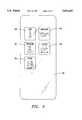
- FIG. 3is a front view of the indicator panel of the present invention.
- FIG. 4is an indicator panel like the indicator panel of FIG. 3 with additional icons included on the panel.
- FIG. 1schematically shows a portable machine 10 which is adapted to be towed between construction sites or other locations where use of the machine is required.
- the machine 10includes a frame 12 which has a trailer hitch 14 or other means for connecting the machine to a truck or another suitable towing vehicle.
- the trailer hitchis located at one end of the frame.
- the portable machine shown schematically in FIG. 1may be any portable type machine, including, but not limited to a fluid compressor, a light tower or a generator.
- the portable machineis driven by an engine 16 which is supported by frame 12.
- the enginemay be powered by any suitable conventional means including gasoline, diesel fuel, or electricity.
- the enginewill be a diesel engine and the portable machine will be a fluid compressor.
- the compressormay be a conventional screw-type compressor that is well known to one skilled in the art with an airend 18 that is connected to the engine to be driven by the engine.
- the compressorincludes a discharge pipe or conduit 20 for flowing compressed gas, such as air, from the compressor to an object of interest.
- a conventional protective shell or shroud 22encloses the engine and airend.
- Engine fuelis stored in a conventional fuel tank 24 and the required electrical power is supplied to the engine by conventional battery 26 which is charged during operation by an alternator 27.
- a fuel line 29ajoins the fuel tank and electrically actuated fuel solenoid 28 and fuel line 29b joins the solenoid with engine 16. In this way, fuel is supplied to the engine when the solenoid is opened.
- the solenoidis grounded by the machine frame.
- the fuel solenoidacts as a means for providing and terminating power to the engine however it is contemplated that in another embodiment with an electrically powered engine the power terminating means may be a circuit breaker.
- Machine 10is provided with a machine diagnosis indicator circuit 30 shown schematically in FIG. 2.
- the circuitis supported by the machine in a conventional manner, well known to one skilled in the art and illuminates at least one LED pair when a machine operating problem is diagnosed by the circuit.
- a means for indicating specifically where the operating problem is locatedis an indicator panel 32 (FIG. 3), that may be mounted on the shroud 22 or frame 12.
- the panelincludes at least one translucent icon member that is illuminated by an associated LED pair when the machine operating problem corresponding to the icon is present.
- machine diagnosis indicator circuit 30includes a three-way switch 34 that is electrically connected to the engine battery 26.
- the switchmay be moved to a start position to start the engine 16 and also may be used to energize and de-energize the diagnosis indicator circuit 30.
- At least one machine protective switchis series wired with the system switch 34 and the fuel solenoid 28.
- the circuit 30 of the present inventionincludes a protective switch series chain comprised of four protective switches 36, 38, 40 and 42 series wired together so that if one switch is opened, power to the fuel solenoid 28 will be interrupted.
- the switchesare conventional single-pole switches well known to one skilled in the art. Four switches are disclosed for purposes of describing the preferred embodiment of the invention however it should be understood that any number of switches may be used.
- Each switchis associated with a particular machine operating parameter and is programmed with predetermined acceptable operating values for the parameter so that during operation of the machine, if the parameter falls outside the predetermined acceptable value the switch will open.
- Switch 36is associated with engine temperature
- switch 38is associated with engine oil pressure
- switch 40is associated with discharge air temperature
- switch 42is associated with fuel level.
- Conventional sensing devices 36a, 38a, 42a, and 40a shown schematically in FIG. 2are located in the desired locations along the engine 16, fuel tank 24 and discharge conduit 20 and each sensing device is connected to the respective switch by a wire or other suitable means.
- An indicator combinationcomprised of an LED annunciator pair 44a and 44b and a resistor 46 is wired in parallel with each of the switches 36, 38, 40 and 42 as shown in FIG. 2.
- the current that flows through and illuminates each LED pairis limited by the resistor.
- a pair of LED annunciatoris necessary to light the icons on panel 32 (FIG. 3). However only one LED annunciator may be used if sufficient to fully illuminate an icon.
- An indicator combinationis wired across each of the switches so that if one of the switches is opened, current flows through the LED pair and illuminates the pair.
- Each LED annunciatoris a super high brightness LED with a rating of 2000-3500 millicandella. Using a super high brightness LED permits the illuminated LED to be visible in all machine operating environments including bright sunlight during daytime operation of the machine.
- the preferred resistor 46is a 270 ohm resistor.
- Resistorsare selected to enable adequate current flow to illuminate a maximum of two LED annunciator pairs across two protective switches with 12 V DC power input. At the same time, maximum current specifications for the LED annunciator pair are not exceeded should only one pair be illuminated.
- Machine 10includes at least one non-protective switch 48.
- the non-protective switch shown in FIG. 2is associated with engine alternator 27 and is integral with the alternator.
- An indicator combinationcomprised of LED annunciator pair 44a and 44b and a resistor 47 are wired through switch 48 so that actuating the switch will cause current to flow through the LED pair and illuminate the pair.
- the preferred resistor 47is a 390 ohm resistor.
- the switch 48is made integral with the alternator and is actuated if the battery charge falls below a predetermined acceptable value. Because the switch 48 is not series wired with the protective switches, the engine does not shut down when switch 48 is actuated and closed.
- Indicator panel (FIG. 3) 32includes translucent icons 50, 52, 54, 56, and 58. Each of the icons overlays a respective indicator combination.
- the iconsgraphically represent the different machine parameters monitored by machine diagnosis circuit 30.
- Icon 50is a combination of a thermometer with the word "AIR” and when illuminated signals high discharge air temperature. The icon 50 overlays the indicator combination associated with switch 40.
- Icon 52is a combination of a thermometer partially immersed in a fluid with the word "ENGINE” and represents high engine temperature and overlays the indicator combination associated with engine temperature switch 36.
- Icon 54is a fuel pump in combination with the word "FUEL" and signifies a low fuel level and overlays the indicator combination associated with switch 42.
- Icon 56is an oil can in combination with the word “ENGINE” signals low oil pressure and overlays the indicator combination associated with oil pressure protective switch 38.
- Icon 58is a battery in combination with the word “VOLTS” and signals low battery voltage and overlays the indicator combination associated with switch 48. When an LED pair is illuminated, the icon which overlays the LED pair will be illuminated and visible to the machine operator and the machine operator will know specifically what the machine problem is and also where the problem is located.
- Additional iconsmay be added to the indicator panel 32.
- icons 60, 62 and 64 associated with engine air filter, general engine service and water level respectivelymay be added.
- Each icon 60, 62, and 64is associated with a non-protective switch and indicator combination like switches 36-42.
- the switches associated with icons 60, 62 and 64are single-pole switches.
- Each indicator combination associated with icons 60, 62 and 64is series wired with the switch (not shown) associated with the icon. When a machine operating parameter falls outside an acceptable range, the respective switch is closed and the associated icon 60, 62 or 64 is illuminated.
- non-protective switches associated with icons 60, 62, and 64are not series wired with the chain of protective switches 36-42 so that if one of the non-protective switches is closed, the engine will not shut down. Any number and combination of icons may be provided on panel 32 for a particular machine.
- the circuit 30may include a conventional relay which allows the machine operator to momentarily activate all the LED annunciators to test the LED's during machine power-up and make sure they will illuminate if required.
- the power to the fuel solenoidis interrupted by the opening of any of the protective switches.
- current that flows through and activates each LED annunciator pair limited by the resistorflows through the solenoid 28 to the ground connection.
- this currentis insufficient to power the fuel solenoid resulting in cutoff of fuel to the engine and then machine shutdown.
- the circuit 30is functional even though the machine is shutdown, and the LED pair stays illuminated even though the machine is not running.
- the LED annunciator pairWhen the switch is opened, the LED annunciator pair provides a visible fault condition that is readily visible to the machine operator. The corresponding icon is illuminated indicating specifically the location of the machine problem.
- a maximum of two protective switchesmay be opened during any single occurrence of a protective machine shutdown. However it is contemplated that in another embodiment of the present invention, greater than two switches may be opened during any single occurrence.
- a machine operating parameter associated with a non-protective switchfalls out of a predetermined acceptable range, the associated non-protective switch is closed, illuminating the LED pair and making the associated icon visible.
- Icons 58-64are associated with the non-protective switches. The machine does not stop running when the non-protective switch is closed and the icon remains illuminated thereby providing a clearly visible reminder to the machine operator of a specific machine problem.
- the inventionprovides direct indication to the machine operator of the status of the protective and non-protective switches using a simple circuit which includes indicator combinations comprised of an LED annunciator pair and resistor.
- the circuit of the present inventioneliminates potential problems associated with more complex diagnostic circuits including relay latching; alternator, starter and device coil electrical interference effects on electronics; and lamp replacement usually required with incandescent bulbs.
Landscapes
- Engineering & Computer Science (AREA)
- Chemical & Material Sciences (AREA)
- Combustion & Propulsion (AREA)
- Mechanical Engineering (AREA)
- General Engineering & Computer Science (AREA)
- Physics & Mathematics (AREA)
- General Physics & Mathematics (AREA)
- Combined Controls Of Internal Combustion Engines (AREA)
Abstract
Description
Claims (10)
Priority Applications (1)
| Application Number | Priority Date | Filing Date | Title |
|---|---|---|---|
| US08/591,331US5691692A (en) | 1996-01-25 | 1996-01-25 | Portable machine with machine diagnosis indicator circuit |
Applications Claiming Priority (1)
| Application Number | Priority Date | Filing Date | Title |
|---|---|---|---|
| US08/591,331US5691692A (en) | 1996-01-25 | 1996-01-25 | Portable machine with machine diagnosis indicator circuit |
Publications (1)
| Publication Number | Publication Date |
|---|---|
| US5691692Atrue US5691692A (en) | 1997-11-25 |
Family
ID=24366072
Family Applications (1)
| Application Number | Title | Priority Date | Filing Date |
|---|---|---|---|
| US08/591,331Expired - LifetimeUS5691692A (en) | 1996-01-25 | 1996-01-25 | Portable machine with machine diagnosis indicator circuit |
Country Status (1)
| Country | Link |
|---|---|
| US (1) | US5691692A (en) |
Cited By (29)
| Publication number | Priority date | Publication date | Assignee | Title |
|---|---|---|---|---|
| US6154122A (en)* | 1999-01-29 | 2000-11-28 | M. P. Menze Research & Development | Snowplow diagnostic system |
| US6323759B1 (en)* | 1999-01-29 | 2001-11-27 | M. P. Menze Research Development Inc. | Snowplow diagnostic system |
| US6336430B2 (en)* | 1998-06-29 | 2002-01-08 | Fatpower Inc. | Hydrogen generating apparatus |
| US6805462B1 (en) | 2002-09-03 | 2004-10-19 | Sullivan-Palatek, Inc. | Towable light tower and power plant |
| US20050126515A1 (en)* | 2001-01-19 | 2005-06-16 | Fatpower Inc. | Hydrogen generating apparatus and components therefor |
| US20060120059A1 (en)* | 2004-12-03 | 2006-06-08 | Dell Products L.P. | System and method for optimizing printed circuit boards to minimize effects of non-uniform dielectric |
| US7878006B2 (en) | 2004-04-27 | 2011-02-01 | Emerson Climate Technologies, Inc. | Compressor diagnostic and protection system and method |
| US20110062725A1 (en)* | 2009-09-17 | 2011-03-17 | Michael Cristoforo | Generator And Carbon Monoxide Detector |
| US20120055446A1 (en)* | 2010-09-08 | 2012-03-08 | Honda Motor Co., Ltd. | Fuel shortage detecting apparatus for general-purpose engine |
| US8160827B2 (en) | 2007-11-02 | 2012-04-17 | Emerson Climate Technologies, Inc. | Compressor sensor module |
| US8393169B2 (en) | 2007-09-19 | 2013-03-12 | Emerson Climate Technologies, Inc. | Refrigeration monitoring system and method |
| US8590325B2 (en) | 2006-07-19 | 2013-11-26 | Emerson Climate Technologies, Inc. | Protection and diagnostic module for a refrigeration system |
| US8964338B2 (en) | 2012-01-11 | 2015-02-24 | Emerson Climate Technologies, Inc. | System and method for compressor motor protection |
| US8974573B2 (en) | 2004-08-11 | 2015-03-10 | Emerson Climate Technologies, Inc. | Method and apparatus for monitoring a refrigeration-cycle system |
| US9140728B2 (en) | 2007-11-02 | 2015-09-22 | Emerson Climate Technologies, Inc. | Compressor sensor module |
| US9285802B2 (en) | 2011-02-28 | 2016-03-15 | Emerson Electric Co. | Residential solutions HVAC monitoring and diagnosis |
| US9310094B2 (en) | 2007-07-30 | 2016-04-12 | Emerson Climate Technologies, Inc. | Portable method and apparatus for monitoring refrigerant-cycle systems |
| US9310439B2 (en) | 2012-09-25 | 2016-04-12 | Emerson Climate Technologies, Inc. | Compressor having a control and diagnostic module |
| US9480177B2 (en) | 2012-07-27 | 2016-10-25 | Emerson Climate Technologies, Inc. | Compressor protection module |
| US9551504B2 (en) | 2013-03-15 | 2017-01-24 | Emerson Electric Co. | HVAC system remote monitoring and diagnosis |
| US9638436B2 (en) | 2013-03-15 | 2017-05-02 | Emerson Electric Co. | HVAC system remote monitoring and diagnosis |
| US9765979B2 (en) | 2013-04-05 | 2017-09-19 | Emerson Climate Technologies, Inc. | Heat-pump system with refrigerant charge diagnostics |
| US9823632B2 (en) | 2006-09-07 | 2017-11-21 | Emerson Climate Technologies, Inc. | Compressor data module |
| US10488090B2 (en) | 2013-03-15 | 2019-11-26 | Emerson Climate Technologies, Inc. | System for refrigerant charge verification |
| US11120652B2 (en)* | 2018-03-21 | 2021-09-14 | Shenzhen Launch Software Co., Ltd. | Method and system for graphically displaying data stream, and vehicle diagnostic device |
| US11352964B2 (en)* | 2017-10-06 | 2022-06-07 | Briggs & Stratton, Llc | Cylinder deactivation for a multiple cylinder engine |
| USD1043749S1 (en)* | 2021-11-05 | 2024-09-24 | Thor Tech, Inc. | Display screen or portion thereof with a transitional graphical user interface |
| USD1050169S1 (en)* | 2021-11-05 | 2024-11-05 | Thor Tech, Inc. | Display screen or portion thereof with a transitional graphical user interface |
| USD1084027S1 (en)* | 2023-12-14 | 2025-07-15 | Caterpillar Inc. | Display screen or portion thereof with graphical user interface |
Citations (6)
| Publication number | Priority date | Publication date | Assignee | Title |
|---|---|---|---|---|
| US2037748A (en)* | 1934-10-29 | 1936-04-21 | Victor F Zahodiakin | Indicating device for engine cooling systems |
| US4502090A (en)* | 1983-02-24 | 1985-02-26 | Sloan Albert H | Protective control system for engine |
| US4727353A (en)* | 1987-01-21 | 1988-02-23 | Deere & Company | Monitor display system |
| US4890088A (en)* | 1988-02-16 | 1989-12-26 | Arthur Woodell | Engine monitoring and control apparatus |
| US4899706A (en)* | 1988-02-03 | 1990-02-13 | Fuji Jukogyo Kabushiki Kaisha | Fuel shortage detection system for engine driven generator |
| US4995357A (en)* | 1989-11-13 | 1991-02-26 | Briggs & Stratton Corporation | Engine shut-off circuit |
- 1996
- 1996-01-25USUS08/591,331patent/US5691692A/ennot_activeExpired - Lifetime
Patent Citations (6)
| Publication number | Priority date | Publication date | Assignee | Title |
|---|---|---|---|---|
| US2037748A (en)* | 1934-10-29 | 1936-04-21 | Victor F Zahodiakin | Indicating device for engine cooling systems |
| US4502090A (en)* | 1983-02-24 | 1985-02-26 | Sloan Albert H | Protective control system for engine |
| US4727353A (en)* | 1987-01-21 | 1988-02-23 | Deere & Company | Monitor display system |
| US4899706A (en)* | 1988-02-03 | 1990-02-13 | Fuji Jukogyo Kabushiki Kaisha | Fuel shortage detection system for engine driven generator |
| US4890088A (en)* | 1988-02-16 | 1989-12-26 | Arthur Woodell | Engine monitoring and control apparatus |
| US4995357A (en)* | 1989-11-13 | 1991-02-26 | Briggs & Stratton Corporation | Engine shut-off circuit |
Cited By (67)
| Publication number | Priority date | Publication date | Assignee | Title |
|---|---|---|---|---|
| US6336430B2 (en)* | 1998-06-29 | 2002-01-08 | Fatpower Inc. | Hydrogen generating apparatus |
| US6323759B1 (en)* | 1999-01-29 | 2001-11-27 | M. P. Menze Research Development Inc. | Snowplow diagnostic system |
| US6154122A (en)* | 1999-01-29 | 2000-11-28 | M. P. Menze Research & Development | Snowplow diagnostic system |
| US20060219190A1 (en)* | 2001-01-19 | 2006-10-05 | Hy-Drive Technologies Ltd. | Hydrogen generating apparatus and components therefor |
| US20050126515A1 (en)* | 2001-01-19 | 2005-06-16 | Fatpower Inc. | Hydrogen generating apparatus and components therefor |
| US7240641B2 (en) | 2001-01-19 | 2007-07-10 | Hy-Drive Technologies Ltd. | Hydrogen generating apparatus and components therefor |
| US6805462B1 (en) | 2002-09-03 | 2004-10-19 | Sullivan-Palatek, Inc. | Towable light tower and power plant |
| US9121407B2 (en) | 2004-04-27 | 2015-09-01 | Emerson Climate Technologies, Inc. | Compressor diagnostic and protection system and method |
| US9669498B2 (en) | 2004-04-27 | 2017-06-06 | Emerson Climate Technologies, Inc. | Compressor diagnostic and protection system and method |
| US7878006B2 (en) | 2004-04-27 | 2011-02-01 | Emerson Climate Technologies, Inc. | Compressor diagnostic and protection system and method |
| US7905098B2 (en) | 2004-04-27 | 2011-03-15 | Emerson Climate Technologies, Inc. | Compressor diagnostic and protection system and method |
| US8474278B2 (en) | 2004-04-27 | 2013-07-02 | Emerson Climate Technologies, Inc. | Compressor diagnostic and protection system and method |
| US10335906B2 (en) | 2004-04-27 | 2019-07-02 | Emerson Climate Technologies, Inc. | Compressor diagnostic and protection system and method |
| US8974573B2 (en) | 2004-08-11 | 2015-03-10 | Emerson Climate Technologies, Inc. | Method and apparatus for monitoring a refrigeration-cycle system |
| US9081394B2 (en) | 2004-08-11 | 2015-07-14 | Emerson Climate Technologies, Inc. | Method and apparatus for monitoring a refrigeration-cycle system |
| US9086704B2 (en) | 2004-08-11 | 2015-07-21 | Emerson Climate Technologies, Inc. | Method and apparatus for monitoring a refrigeration-cycle system |
| US10558229B2 (en) | 2004-08-11 | 2020-02-11 | Emerson Climate Technologies Inc. | Method and apparatus for monitoring refrigeration-cycle systems |
| US9046900B2 (en) | 2004-08-11 | 2015-06-02 | Emerson Climate Technologies, Inc. | Method and apparatus for monitoring refrigeration-cycle systems |
| US9023136B2 (en) | 2004-08-11 | 2015-05-05 | Emerson Climate Technologies, Inc. | Method and apparatus for monitoring a refrigeration-cycle system |
| US9690307B2 (en) | 2004-08-11 | 2017-06-27 | Emerson Climate Technologies, Inc. | Method and apparatus for monitoring refrigeration-cycle systems |
| US9021819B2 (en) | 2004-08-11 | 2015-05-05 | Emerson Climate Technologies, Inc. | Method and apparatus for monitoring a refrigeration-cycle system |
| US9304521B2 (en) | 2004-08-11 | 2016-04-05 | Emerson Climate Technologies, Inc. | Air filter monitoring system |
| US9017461B2 (en) | 2004-08-11 | 2015-04-28 | Emerson Climate Technologies, Inc. | Method and apparatus for monitoring a refrigeration-cycle system |
| US7292454B2 (en) | 2004-12-03 | 2007-11-06 | Dell Products L.P. | System and method for optimizing printed circuit boards to minimize effects of non-uniform dielectric |
| US20060120059A1 (en)* | 2004-12-03 | 2006-06-08 | Dell Products L.P. | System and method for optimizing printed circuit boards to minimize effects of non-uniform dielectric |
| US8590325B2 (en) | 2006-07-19 | 2013-11-26 | Emerson Climate Technologies, Inc. | Protection and diagnostic module for a refrigeration system |
| US9885507B2 (en) | 2006-07-19 | 2018-02-06 | Emerson Climate Technologies, Inc. | Protection and diagnostic module for a refrigeration system |
| US9823632B2 (en) | 2006-09-07 | 2017-11-21 | Emerson Climate Technologies, Inc. | Compressor data module |
| US10352602B2 (en) | 2007-07-30 | 2019-07-16 | Emerson Climate Technologies, Inc. | Portable method and apparatus for monitoring refrigerant-cycle systems |
| US9310094B2 (en) | 2007-07-30 | 2016-04-12 | Emerson Climate Technologies, Inc. | Portable method and apparatus for monitoring refrigerant-cycle systems |
| US8393169B2 (en) | 2007-09-19 | 2013-03-12 | Emerson Climate Technologies, Inc. | Refrigeration monitoring system and method |
| US9651286B2 (en) | 2007-09-19 | 2017-05-16 | Emerson Climate Technologies, Inc. | Refrigeration monitoring system and method |
| US9194894B2 (en) | 2007-11-02 | 2015-11-24 | Emerson Climate Technologies, Inc. | Compressor sensor module |
| US9140728B2 (en) | 2007-11-02 | 2015-09-22 | Emerson Climate Technologies, Inc. | Compressor sensor module |
| US10458404B2 (en) | 2007-11-02 | 2019-10-29 | Emerson Climate Technologies, Inc. | Compressor sensor module |
| US8160827B2 (en) | 2007-11-02 | 2012-04-17 | Emerson Climate Technologies, Inc. | Compressor sensor module |
| US8335657B2 (en) | 2007-11-02 | 2012-12-18 | Emerson Climate Technologies, Inc. | Compressor sensor module |
| US8534258B2 (en)* | 2009-09-17 | 2013-09-17 | Daydream Believers, Llc | Generator and carbon monoxide detector |
| US20110062725A1 (en)* | 2009-09-17 | 2011-03-17 | Michael Cristoforo | Generator And Carbon Monoxide Detector |
| US8770172B2 (en)* | 2010-09-08 | 2014-07-08 | Honda Motor Co., Ltd. | Fuel shortage detecting apparatus for general-purpose engine |
| US20120055446A1 (en)* | 2010-09-08 | 2012-03-08 | Honda Motor Co., Ltd. | Fuel shortage detecting apparatus for general-purpose engine |
| US10884403B2 (en) | 2011-02-28 | 2021-01-05 | Emerson Electric Co. | Remote HVAC monitoring and diagnosis |
| US9703287B2 (en) | 2011-02-28 | 2017-07-11 | Emerson Electric Co. | Remote HVAC monitoring and diagnosis |
| US10234854B2 (en) | 2011-02-28 | 2019-03-19 | Emerson Electric Co. | Remote HVAC monitoring and diagnosis |
| US9285802B2 (en) | 2011-02-28 | 2016-03-15 | Emerson Electric Co. | Residential solutions HVAC monitoring and diagnosis |
| US8964338B2 (en) | 2012-01-11 | 2015-02-24 | Emerson Climate Technologies, Inc. | System and method for compressor motor protection |
| US9590413B2 (en) | 2012-01-11 | 2017-03-07 | Emerson Climate Technologies, Inc. | System and method for compressor motor protection |
| US9876346B2 (en) | 2012-01-11 | 2018-01-23 | Emerson Climate Technologies, Inc. | System and method for compressor motor protection |
| US10028399B2 (en) | 2012-07-27 | 2018-07-17 | Emerson Climate Technologies, Inc. | Compressor protection module |
| US9480177B2 (en) | 2012-07-27 | 2016-10-25 | Emerson Climate Technologies, Inc. | Compressor protection module |
| US10485128B2 (en) | 2012-07-27 | 2019-11-19 | Emerson Climate Technologies, Inc. | Compressor protection module |
| US9310439B2 (en) | 2012-09-25 | 2016-04-12 | Emerson Climate Technologies, Inc. | Compressor having a control and diagnostic module |
| US9762168B2 (en) | 2012-09-25 | 2017-09-12 | Emerson Climate Technologies, Inc. | Compressor having a control and diagnostic module |
| US10274945B2 (en) | 2013-03-15 | 2019-04-30 | Emerson Electric Co. | HVAC system remote monitoring and diagnosis |
| US10775084B2 (en) | 2013-03-15 | 2020-09-15 | Emerson Climate Technologies, Inc. | System for refrigerant charge verification |
| US9551504B2 (en) | 2013-03-15 | 2017-01-24 | Emerson Electric Co. | HVAC system remote monitoring and diagnosis |
| US9638436B2 (en) | 2013-03-15 | 2017-05-02 | Emerson Electric Co. | HVAC system remote monitoring and diagnosis |
| US10488090B2 (en) | 2013-03-15 | 2019-11-26 | Emerson Climate Technologies, Inc. | System for refrigerant charge verification |
| US9765979B2 (en) | 2013-04-05 | 2017-09-19 | Emerson Climate Technologies, Inc. | Heat-pump system with refrigerant charge diagnostics |
| US10060636B2 (en) | 2013-04-05 | 2018-08-28 | Emerson Climate Technologies, Inc. | Heat pump system with refrigerant charge diagnostics |
| US10443863B2 (en) | 2013-04-05 | 2019-10-15 | Emerson Climate Technologies, Inc. | Method of monitoring charge condition of heat pump system |
| US11352964B2 (en)* | 2017-10-06 | 2022-06-07 | Briggs & Stratton, Llc | Cylinder deactivation for a multiple cylinder engine |
| US11120652B2 (en)* | 2018-03-21 | 2021-09-14 | Shenzhen Launch Software Co., Ltd. | Method and system for graphically displaying data stream, and vehicle diagnostic device |
| USD1043749S1 (en)* | 2021-11-05 | 2024-09-24 | Thor Tech, Inc. | Display screen or portion thereof with a transitional graphical user interface |
| USD1050169S1 (en)* | 2021-11-05 | 2024-11-05 | Thor Tech, Inc. | Display screen or portion thereof with a transitional graphical user interface |
| USD1092543S1 (en) | 2021-11-05 | 2025-09-09 | Thor Tech, Inc. | Display screen or portion thereof with a transitional graphical user interface |
| USD1084027S1 (en)* | 2023-12-14 | 2025-07-15 | Caterpillar Inc. | Display screen or portion thereof with graphical user interface |
Similar Documents
| Publication | Publication Date | Title |
|---|---|---|
| US5691692A (en) | Portable machine with machine diagnosis indicator circuit | |
| US3975708A (en) | Vehicle condition monitoring system | |
| US4884033A (en) | Diagnostic test apparatus for electrical system of automotive vehicle | |
| US4053868A (en) | Vehicle system monitor | |
| US5949330A (en) | Method and apparatus for displaying sensor outputs in a diagnostic system | |
| JPH06234335A (en) | Computerized diagnostic and monitoring system | |
| US3644915A (en) | Filter bypass indicator | |
| US4764727A (en) | Circuit continuity and voltage tester | |
| JPH06174600A (en) | Method and device for displaying change of state | |
| AU740359B2 (en) | Electrical tester for small motor vehicles | |
| US3744046A (en) | Engine heater monitor and control system | |
| US3566401A (en) | Engine warning circuit | |
| US3196389A (en) | Vehicle engine oil level and pressure responsive indicator | |
| US6323759B1 (en) | Snowplow diagnostic system | |
| US4162478A (en) | Circuit arrangement for testing operating and/or capacity conditions in automotive vehicles | |
| CN100368670C (en) | Diagnosis system for liquefied petroleum injection fuel pump | |
| US4086812A (en) | Display device | |
| US4584526A (en) | Combination continuity and live circuit path tester | |
| CA1036687A (en) | Multiple input warning system for a motor vehicle | |
| US4642604A (en) | Auxiliary lubrication pump apparatus | |
| US3586868A (en) | Zero current transfer device | |
| JPS642772B2 (en) | ||
| US4565963A (en) | Test circuit for motor vehicle speed control | |
| GB2172456A (en) | A device for monitoring the operation of the lights circuit of a trailer of a commercial vehicle | |
| US4214227A (en) | Instrument panel assembly |
Legal Events
| Date | Code | Title | Description |
|---|---|---|---|
| AS | Assignment | Owner name:INGERSOLL-RAND COMPANY, NEW JERSEY Free format text:ASSIGNMENT OF ASSIGNORS INTEREST;ASSIGNOR:HERBSTRITT, DALE R.;REEL/FRAME:008101/0452 Effective date:19960122 | |
| STCF | Information on status: patent grant | Free format text:PATENTED CASE | |
| FEPP | Fee payment procedure | Free format text:PAYOR NUMBER ASSIGNED (ORIGINAL EVENT CODE: ASPN); ENTITY STATUS OF PATENT OWNER: LARGE ENTITY | |
| FPAY | Fee payment | Year of fee payment:4 | |
| REMI | Maintenance fee reminder mailed | ||
| FPAY | Fee payment | Year of fee payment:8 | |
| SULP | Surcharge for late payment | Year of fee payment:7 | |
| AS | Assignment | Owner name:DOOSAN INTERNATIONAL USA, INC., GEORGIA Free format text:ASSIGNMENT OF ASSIGNORS INTEREST;ASSIGNOR:INGERSOLL-RAND COMPANY;REEL/FRAME:020243/0832 Effective date:20071130 | |
| AS | Assignment | Owner name:HSBC BANK PLC, UNITED KINGDOM Free format text:SECURITY AGREEMENT;ASSIGNOR:DOOSAN INTERNATIONAL USA, INC.;REEL/FRAME:020468/0836 Effective date:20080129 | |
| AS | Assignment | Owner name:CLARK EQUIPMENT COMPANY, NORTH DAKOTA Free format text:MERGER;ASSIGNOR:DOOSAN INTERNATIONAL USA, INC.;REEL/FRAME:022151/0137 Effective date:20081231 | |
| AS | Assignment | Owner name:DOOSAN INTERNATIONAL USA, INC., NORTH CAROLINA Free format text:ASSIGNMENT OF ASSIGNORS INTEREST;ASSIGNOR:INGERSOLL-RAND COMPANY;REEL/FRAME:022235/0134 Effective date:20071130 | |
| FPAY | Fee payment | Year of fee payment:12 | |
| AS | Assignment | Owner name:CLARK EQUIPMENT COMPANY, NORTH DAKOTA Free format text:RELEASE OF SECURITY INTEREST;ASSIGNOR:HSBC BANK PLC;REEL/FRAME:033062/0254 Effective date:20120808 | |
| AS | Assignment | Owner name:JPMORGAN CHASE BANK, N.A., AS ADMINISTRATIVE AGENT Free format text:PATENT SECURITY AGREEMENT-ABL;ASSIGNORS:DOOSAN INFRACORE INTERNATIONAL, INC.;CLARK EQUIPMENT COMPANY;REEL/FRAME:033085/0873 Effective date:20140528 Owner name:JPMORGAN CHASE BANK, N.A., AS ADMINISTRATIVE AGENT Free format text:PATENT SECURITY AGREEMENT-TERM LOAN;ASSIGNORS:DOOSAN INFRACORE INTERNATIONAL, INC.;CLARK EQUIPMENT COMPANY;REEL/FRAME:033085/0916 Effective date:20140528 | |
| AS | Assignment | Owner name:CLARK EQUIPMENT COMPANY, DELAWARE Free format text:MERGER;ASSIGNORS:DOOSAN INFRACORE INTERNATIONAL, INC.;CLARK EQUIPMENT COMPANY;REEL/FRAME:042500/0899 Effective date:20160630 | |
| AS | Assignment | Owner name:CLARK EQUIPMENT COMPANY, DELAWARE Free format text:RELEASE OF PATENT SECURITY AGREEMENT-ABL;ASSIGNOR:JPMORGAN CHASE BANK, N.A., AS ADMINISTRATIVE AGENT;REEL/FRAME:042563/0747 Effective date:20170518 Owner name:CLARK EQUIPMENT COMPANY, DELAWARE Free format text:RELEASE OF PATENT SECURITY AGREEMENT-TERM LOAN;ASSIGNOR:JPMORGAN CHASE BANK, N.A., AS ADMINISTRATIVE AGENT;REEL/FRAME:042563/0801 Effective date:20170518 |