US5690816A - Anti-drain back/pressure relieved filter cartridges - Google Patents
Anti-drain back/pressure relieved filter cartridgesDownload PDFInfo
- Publication number
- US5690816A US5690816AUS08/556,595US55659595AUS5690816AUS 5690816 AUS5690816 AUS 5690816AUS 55659595 AUS55659595 AUS 55659595AUS 5690816 AUS5690816 AUS 5690816A
- Authority
- US
- United States
- Prior art keywords
- filter element
- annular
- end plate
- valve member
- outer sleeve
- Prior art date
- Legal status (The legal status is an assumption and is not a legal conclusion. Google has not performed a legal analysis and makes no representation as to the accuracy of the status listed.)
- Expired - Lifetime
Links
Images


Classifications
- B—PERFORMING OPERATIONS; TRANSPORTING
- B01—PHYSICAL OR CHEMICAL PROCESSES OR APPARATUS IN GENERAL
- B01D—SEPARATION
- B01D27/00—Cartridge filters of the throw-away type
- B01D27/04—Cartridge filters of the throw-away type with cartridges made of a piece of unitary material, e.g. filter paper
- B01D27/06—Cartridge filters of the throw-away type with cartridges made of a piece of unitary material, e.g. filter paper with corrugated, folded or wound material
- B—PERFORMING OPERATIONS; TRANSPORTING
- B01—PHYSICAL OR CHEMICAL PROCESSES OR APPARATUS IN GENERAL
- B01D—SEPARATION
- B01D27/00—Cartridge filters of the throw-away type
- B01D27/10—Safety devices, e.g. by-passes
- B01D27/103—Bypass or safety valves
- B—PERFORMING OPERATIONS; TRANSPORTING
- B01—PHYSICAL OR CHEMICAL PROCESSES OR APPARATUS IN GENERAL
- B01D—SEPARATION
- B01D27/00—Cartridge filters of the throw-away type
- B01D27/10—Safety devices, e.g. by-passes
- B01D27/106—Anti-leakage or anti-return valves
- Y—GENERAL TAGGING OF NEW TECHNOLOGICAL DEVELOPMENTS; GENERAL TAGGING OF CROSS-SECTIONAL TECHNOLOGIES SPANNING OVER SEVERAL SECTIONS OF THE IPC; TECHNICAL SUBJECTS COVERED BY FORMER USPC CROSS-REFERENCE ART COLLECTIONS [XRACs] AND DIGESTS
- Y10—TECHNICAL SUBJECTS COVERED BY FORMER USPC
- Y10S—TECHNICAL SUBJECTS COVERED BY FORMER USPC CROSS-REFERENCE ART COLLECTIONS [XRACs] AND DIGESTS
- Y10S210/00—Liquid purification or separation
- Y10S210/17—Twist-on
Definitions
- the present inventionrelates to improvements in anti-drain back/pressure relieved filter cartridges. More particularly, the present invention relates to improvements in valve configurations for such filter cartridges and in improvements in configurations for retaining annular filter elements and valve components within filter cartridges.
- Annular filter elementsare mounted in filter housings to form replaceable filter cartridges which are threadably mounted on internal combustion engines. These cartridges are known as "spin-on filters" because they are threadably mounted and removable. If a customer follows the recommended procedures for changing the filter cartridge when lubricating oil is changed, then it is unusual for the filter to clog; however, if the customer fails to change the filter cartridge, or if the lubricating oil becomes contaminated for some other reason, the filter can become clogged or either blocked or minimize flow of lubricating oil to the engine. If this happens, an engine can be destroyed or seriously damaged.
- filter cartridgeshave been configured to allow oil to bypass filter elements in the cartridges when the filter elements become clogged.
- the engineis thereafter supplied with at least unfiltered lubricant rather than no lubricant at all, or insufficient lubricant.
- a lubricating oil filter cartridgein the present invention, includes a housing with an annular filter element therein and an end plate, the end plate having inlet openings therethrough for allowing unfiltered lubricating oil to enter the housing and a central outlet for allowing filtered oil to pass out of the filter housing.
- the improvementcomprises an annular valve support disposed between the end plate and the filter element, the annular valve element having an inner sleeve bearing against the end plate proximate the outlet and an outer sleeve with a plurality of holes therethrough for allowing lubricating oil to bypass the filter element when the holes are uncovered by an annular valve member.
- the annular valve supportfurther has a radially extending flange which underlies the annular filter element.
- the annular valve memberhas a flexible shirt which functions as an anti-drain back valve and an expandable collar fitting around the outer sleeve of the annular valve support to function as a bypass valve.
- the expandable collarIn order to function as a bypass valve, the expandable collar normally covers the holes but and spreads to uncover the holes when the filter element becomes clogged. Consequently, unfiltered lubricating oil normally passes through the annular filter element, but when the filter element becomes clogged, bypasses the annular filter element and flows through the holes in the annular filter support.
- the annular valve memberis disposed between the annular filter element and the outer sleeve of the annular valve support with the radially extending flap disposed between the radially extending flange of the annular valve support and the filter element.
- the annular valve supportis made of metal which may, for example, be steel.
- FIG. 1is a side view, partially in section, of an anti-drain back/pressure relievable filter cartridge configured in accordance with the principles of the present invention, showing the filter cartridge in an anti-drain back mode when the filter is connected to an engine which is not running;
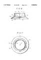
- FIG. 2is an end view of a bottom end cap used with a filter element supported in the filter cartridge of FIGS. 1--3;
- FIG. 3is a side elevation of the end cap of FIG. 2 taken along lines 3--3 of FIG. 2;
- FIG. 4is a side elevation of a combination valve member and filter element support
- FIG. 5is an end view of the support of FIG. 4;
- FIG. 6is a side elevation of an annular valve member which is supported by the annular filter element and valve member support of FIGS. 4 and 5;
- FIG. 7is a top view of the valve member of FIG. 6.
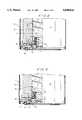
- FIG. 8is an enlarged view of a portion of the filter cartridge of FIG. 1, but showing the filter cartridge in an active mode filtering lubricating oil circulating in an operating engine;
- FIG. 9is a view similar to FIG. 8, but showing the filter cartridge operating in a bypass mode when the filter element is clogged;
- a lubricating oil filter cartridge 10configured in accordance with the present invention, wherein the cartridge comprises an annular filter element 12 configured of a conventional pleated paper filament media 13, or some other filter material, contained within a cylindrical housing 14.
- the annular filter element 12is concentric with respect to an axis 16 of the cartridge 10 and has a hollow core 18.
- the annular filter element 12has a first end 19 configured as a closed, dished end cap 20 which is abutted by a spring 21 that is seated in a depression 22 within the closed, dished end cap (see FIGS. 2 and 3).
- a spring 21that is seated in a depression 22 within the closed, dished end cap (see FIGS. 2 and 3).
- annular end cap 23At the second end of the annular filter element 12, there is an annular end cap 23 having an outer axial flange 24 and an inner axial flange 27 surrounding a central opening 28.
- the inner axial flange 27is aligned with the hollow core 18 of the filter element.
- the inner and outer axial flangesare connected to one another via a radially extending plate 29 which has an annular stiffening offset 30 therein.
- An end plate 31encloses the filter element 12 in the housing 14.
- the end plate 30includes a threaded outlet 32, coaxial with the axis 16 of the filter cartridge 10 and a plurality of inlet openings 34 (only one of which is shown) disposed in spaced relation with one another around the axis 16 of the cartridge 10.
- the end cap 30is held proximate the end of the housing by a cover 36 which is crimped to the bottom end of the housing 14 by a peripheral crimp 38.
- An annular seal 40seals the inlet openings 34 with respect to the environment surrounding the filter cartridge 10.
- FIGS. 4 and 5there is shown a combination valve member and filter element support 45 preferably made of metal but can also be made of plastic.
- the support 45has an inner sleeve 46 with an annular rolled stiffener 48 and an outer sleeve 50 which is connected to the inner sleeve by an annular, arcuate bight 52.
- the outer sleeve 50has a radial flange 54 extending outwardly therefrom, the radial flange terminating in an upper convex surface 56.
- FIG. 1in combination with FIGS. 4 and 5, it is seen that the filter and valve member support 45 is seated against the end plate 30 coaxially with the internally threaded outlet 32.
- the rolled end stiffener 48forms an annular foot surrounding the outlet 32.
- the inner and outer sleeves 46 and 50 of the support 45are received within the central opening 28 of the end cap 23 shown in FIGS. 2 and 3.
- the end cap 23also overlies the radial flange 54 of the combined valve member and filter element support 45.
- valve member 60which is comprised of an expandable collar portion 62 and a skirt portion 64.
- the collar 60is preferably made of a material such as Goshen 2624 which is a rubber like low swell silicone material available from the Goshen Rubber Company.
- the skirt 64has a frustoconical portion 66 which has a periphery 67 and a generally radial section 68 that joins the frustoconical section to the expandable collar portion 62.
- Disposed around the exterior of the radial collar portion 62 and a lower section 72 thereofare a plurality of fibs 74.
- the ribs 74extend slightly past the lower portion 72 of the expandable collar to overlie part of an upper portion 76 and stiffen the portion of the collar portion on which they are located.
- the upper portion 76is separated from the lower portion of the expandable collar 62 by a very narrow annular shoulder 78.
- the upper portionhas an inner diameter of about 1/100ths of an inch less than the lower portion 72.
- valve member 60 of FIGS. 7 and 8fits over the combined valve member and filter element support 45 of FIGS. 4 and 5 and, as is seen in FIGS. 1 has the annular end cap 23 of the filter element 12 urged thereagainst by the coil spring 21.
- the inner axial flange 27 of the end cap 23is adjacent to and engages the ribs 74 on the expandable collar 62 and an inner peripheral portion of the plate 29 abuts the radially extending portion 68 of the skirt 64.
- the frustoconical portion 66 of the skirt 64drapes over the upper convex surface 56 of the radial flange 54 with the peripheral end 67 of the skirt resting on the end plate 30.
- skirt 64Normally, when the engine (not shown) to which the canister 10 is connected is not operating (see FIG. 1), lubricating oil in the canister is retained in the canister by the skirt 64 because the frustoconical portion 66 of the skirt prevents lubricating oil from flowing out of the inlet holes 34. Accordingly, the skirt 64 functions as an anti-drain back valve.
- the frustoconical portion 66 of the skirt 64deflects upwardly, allowing lubricating oil to flow in the direction of the arrows 85, wherein the lubricating oil flows around the outside of the filter element 12 and is forced radially therethrough into the hollow core 18 of the filter element, from which it then flows through the internally threaded out 32 and out of the filter cartridge 10.
- the unitary valve member 60performs both the pressure relief and anti-drain back functions without the need for an additional spring.
- the valve member 60By making the valve member 60 of a material such as the preferred material, Goshen 2624, the bias necessary to close the valve member is unitary with its structure.
Landscapes
- Chemical & Material Sciences (AREA)
- Chemical Kinetics & Catalysis (AREA)
- Lubrication Details And Ventilation Of Internal Combustion Engines (AREA)
- Filtration Of Liquid (AREA)
Abstract
Description
Claims (20)
Priority Applications (9)
| Application Number | Priority Date | Filing Date | Title |
|---|---|---|---|
| US08/556,595US5690816A (en) | 1995-11-13 | 1995-11-13 | Anti-drain back/pressure relieved filter cartridges |
| US08/653,715US5833843A (en) | 1995-11-13 | 1996-05-23 | Anti-drain back/pressure relieved filter cartridges |
| US08/741,968US6096199A (en) | 1995-11-13 | 1996-10-31 | Oil filter cartridge with temperature sensitive bypass valve |
| GB9623430AGB2307189B (en) | 1995-11-13 | 1996-11-11 | Improvements in anti-drain back/pressure relieved filter cartridges |
| GB9927010AGB2342595B (en) | 1995-11-13 | 1996-11-11 | Improvements in anti-drain back/pressure relieved filter cartridges |
| MX9605525AMX9605525A (en) | 1995-11-13 | 1996-11-12 | Improvements in anti-drain back/pressure relieved filter cartridges. |
| CA002190076ACA2190076C (en) | 1995-11-13 | 1996-11-12 | Improvements in anti-drain back/pressure relieved filter cartridges |
| BR9605551ABR9605551A (en) | 1995-11-13 | 1996-11-13 | Improvements in filter cartridges with flow back and pressure relief |
| US09/040,422US6027640A (en) | 1995-11-13 | 1998-03-18 | Anti-drain back/pressure relieved filter cartridges |
Applications Claiming Priority (1)
| Application Number | Priority Date | Filing Date | Title |
|---|---|---|---|
| US08/556,595US5690816A (en) | 1995-11-13 | 1995-11-13 | Anti-drain back/pressure relieved filter cartridges |
Related Child Applications (1)
| Application Number | Title | Priority Date | Filing Date |
|---|---|---|---|
| US08/653,715Continuation-In-PartUS5833843A (en) | 1995-11-13 | 1996-05-23 | Anti-drain back/pressure relieved filter cartridges |
Publications (1)
| Publication Number | Publication Date |
|---|---|
| US5690816Atrue US5690816A (en) | 1997-11-25 |
Family
ID=24222007
Family Applications (1)
| Application Number | Title | Priority Date | Filing Date |
|---|---|---|---|
| US08/556,595Expired - LifetimeUS5690816A (en) | 1995-11-13 | 1995-11-13 | Anti-drain back/pressure relieved filter cartridges |
Country Status (1)
| Country | Link |
|---|---|
| US (1) | US5690816A (en) |
Cited By (13)
| Publication number | Priority date | Publication date | Assignee | Title |
|---|---|---|---|---|
| US6027646A (en)* | 1998-04-06 | 2000-02-22 | Caterpillar Inc. | Canister oil filter with improved filter sealing |
| US6027640A (en)* | 1995-11-13 | 2000-02-22 | Dana Corporation | Anti-drain back/pressure relieved filter cartridges |
| US6214215B1 (en) | 1999-03-17 | 2001-04-10 | Alliedsignal Inc. | Resilient oil filter seal with pressure relief valves |
| US6284130B1 (en) | 1999-02-04 | 2001-09-04 | Dana Corporation | Filter cartridge with clean side anti-drainback valve |
| US20030178351A1 (en)* | 2002-03-19 | 2003-09-25 | Doyle E. Michael | Multi-stage EDM filter |
| US20040164007A1 (en)* | 2003-02-26 | 2004-08-26 | Bhardwaj Arun K. | Center tube with integrated relief valve |
| US20040173512A1 (en)* | 2003-03-03 | 2004-09-09 | Frye Randy C. | Washer relief valve assembly |
| US20060021952A1 (en)* | 2003-09-11 | 2006-02-02 | Skinkle David W | Apparatus for separating blood components |
| US20060054547A1 (en)* | 2004-09-13 | 2006-03-16 | Baldwin Filters, Inc. | Fuel filter cartridge and keyed end cap |
| US20090211955A1 (en)* | 2008-02-27 | 2009-08-27 | Purolator Filters Na Llc | Anti-Drainback Valve with Position Positive Locking for Spin-on Oil and Fuel Filters |
| US7662284B2 (en) | 2004-06-29 | 2010-02-16 | Donaldson Company, Inc. | Liquid filter arrangement and methods |
| US20100078375A1 (en)* | 2008-09-30 | 2010-04-01 | Caterpillar Inc. | Filter assembly |
| US8293103B2 (en) | 2005-12-08 | 2012-10-23 | Donaldson Company, Inc. | Spin-on filter assembly and methods |
Citations (20)
| Publication number | Priority date | Publication date | Assignee | Title |
|---|---|---|---|---|
| US2092162A (en)* | 1936-05-25 | 1937-09-07 | Thomas M Lyons | Game apparatus |
| US2183616A (en)* | 1939-12-19 | Fuel filter | ||
| US2937756A (en)* | 1954-12-29 | 1960-05-24 | Wix Corp | Filter unit |
| US3132097A (en)* | 1960-03-28 | 1964-05-05 | Walker Mfg Co | Filter |
| CA722021A (en)* | 1965-11-23 | I. Thornton Donald | Filters | |
| US3231089A (en)* | 1963-01-24 | 1966-01-25 | Fram Corp | Filters |
| US3235085A (en)* | 1962-01-08 | 1966-02-15 | Wix Corp | Filter unit having dual purpose valve assembly |
| US3243045A (en)* | 1960-03-28 | 1966-03-29 | Walker Mfg Co | Filter |
| US3305095A (en)* | 1964-06-11 | 1967-02-21 | Walker Mfg Co | Filter having a flat resilient disc serving as both a relief and check valve |
| US3332554A (en)* | 1966-05-04 | 1967-07-25 | Wix Corp | Filter unit employing in combination one-way and pressure relief valve |
| US3529722A (en)* | 1969-05-22 | 1970-09-22 | Wix Corp | Combined anti-drain back valve and by-pass valve |
| US3557957A (en)* | 1968-05-31 | 1971-01-26 | Baldwin Mfg Co J A | Filter assembly having a two-way bypass valve therein |
| US3567023A (en)* | 1968-07-13 | 1971-03-02 | Gen Motors Corp | Valved filter support tube |
| US3785491A (en)* | 1971-10-28 | 1974-01-15 | Purolator Inc | Filter anti-drainback and relief valves |
| GB1525689A (en)* | 1976-07-01 | 1978-09-20 | Gen Motors Corp | Pressure vessels |
| US4144168A (en)* | 1977-10-26 | 1979-03-13 | Fram Corporation | Fluid filter |
| US4732678A (en)* | 1986-05-01 | 1988-03-22 | Wix Corporation | Filter body having closely adjacent filter material |
| US4872976A (en)* | 1988-07-25 | 1989-10-10 | Baldwin Filters, Inc. | Oil filter with multiple function valve |
| US5284579A (en)* | 1992-08-31 | 1994-02-08 | Dana Corporation | One-piece anti-drainback and relief valve |
| US5405527A (en)* | 1994-02-24 | 1995-04-11 | Dana Corporation | Anti-drainback/pressure-relieved filter cartridges for lubricating oil |
- 1995
- 1995-11-13USUS08/556,595patent/US5690816A/ennot_activeExpired - Lifetime
Patent Citations (20)
| Publication number | Priority date | Publication date | Assignee | Title |
|---|---|---|---|---|
| US2183616A (en)* | 1939-12-19 | Fuel filter | ||
| CA722021A (en)* | 1965-11-23 | I. Thornton Donald | Filters | |
| US2092162A (en)* | 1936-05-25 | 1937-09-07 | Thomas M Lyons | Game apparatus |
| US2937756A (en)* | 1954-12-29 | 1960-05-24 | Wix Corp | Filter unit |
| US3132097A (en)* | 1960-03-28 | 1964-05-05 | Walker Mfg Co | Filter |
| US3243045A (en)* | 1960-03-28 | 1966-03-29 | Walker Mfg Co | Filter |
| US3235085A (en)* | 1962-01-08 | 1966-02-15 | Wix Corp | Filter unit having dual purpose valve assembly |
| US3231089A (en)* | 1963-01-24 | 1966-01-25 | Fram Corp | Filters |
| US3305095A (en)* | 1964-06-11 | 1967-02-21 | Walker Mfg Co | Filter having a flat resilient disc serving as both a relief and check valve |
| US3332554A (en)* | 1966-05-04 | 1967-07-25 | Wix Corp | Filter unit employing in combination one-way and pressure relief valve |
| US3557957A (en)* | 1968-05-31 | 1971-01-26 | Baldwin Mfg Co J A | Filter assembly having a two-way bypass valve therein |
| US3567023A (en)* | 1968-07-13 | 1971-03-02 | Gen Motors Corp | Valved filter support tube |
| US3529722A (en)* | 1969-05-22 | 1970-09-22 | Wix Corp | Combined anti-drain back valve and by-pass valve |
| US3785491A (en)* | 1971-10-28 | 1974-01-15 | Purolator Inc | Filter anti-drainback and relief valves |
| GB1525689A (en)* | 1976-07-01 | 1978-09-20 | Gen Motors Corp | Pressure vessels |
| US4144168A (en)* | 1977-10-26 | 1979-03-13 | Fram Corporation | Fluid filter |
| US4732678A (en)* | 1986-05-01 | 1988-03-22 | Wix Corporation | Filter body having closely adjacent filter material |
| US4872976A (en)* | 1988-07-25 | 1989-10-10 | Baldwin Filters, Inc. | Oil filter with multiple function valve |
| US5284579A (en)* | 1992-08-31 | 1994-02-08 | Dana Corporation | One-piece anti-drainback and relief valve |
| US5405527A (en)* | 1994-02-24 | 1995-04-11 | Dana Corporation | Anti-drainback/pressure-relieved filter cartridges for lubricating oil |
Cited By (25)
| Publication number | Priority date | Publication date | Assignee | Title |
|---|---|---|---|---|
| US6027640A (en)* | 1995-11-13 | 2000-02-22 | Dana Corporation | Anti-drain back/pressure relieved filter cartridges |
| US6027646A (en)* | 1998-04-06 | 2000-02-22 | Caterpillar Inc. | Canister oil filter with improved filter sealing |
| US6284130B1 (en) | 1999-02-04 | 2001-09-04 | Dana Corporation | Filter cartridge with clean side anti-drainback valve |
| US6214215B1 (en) | 1999-03-17 | 2001-04-10 | Alliedsignal Inc. | Resilient oil filter seal with pressure relief valves |
| US20030178351A1 (en)* | 2002-03-19 | 2003-09-25 | Doyle E. Michael | Multi-stage EDM filter |
| US6881330B2 (en) | 2002-03-19 | 2005-04-19 | Hoff Engineering Co., Inc. | Multi-stage EDM filter |
| US20040164007A1 (en)* | 2003-02-26 | 2004-08-26 | Bhardwaj Arun K. | Center tube with integrated relief valve |
| US20040173512A1 (en)* | 2003-03-03 | 2004-09-09 | Frye Randy C. | Washer relief valve assembly |
| US20060021952A1 (en)* | 2003-09-11 | 2006-02-02 | Skinkle David W | Apparatus for separating blood components |
| US7955502B2 (en) | 2004-06-29 | 2011-06-07 | Donaldson Company, Inc. | Liquid filter arrangement and methods |
| US11673082B2 (en) | 2004-06-29 | 2023-06-13 | Donaldson Company, Inc. | Liquid filter arrangements and methods |
| US7662284B2 (en) | 2004-06-29 | 2010-02-16 | Donaldson Company, Inc. | Liquid filter arrangement and methods |
| US10646803B2 (en) | 2004-06-29 | 2020-05-12 | Donaldson Company, Inc. | Liquid filter arrangement and methods |
| US9120041B2 (en) | 2004-06-29 | 2015-09-01 | Donaldson Company, Inc. | Liquid filter arrangement and methods |
| US8440079B2 (en) | 2004-06-29 | 2013-05-14 | Donaldson Company, Inc. | Liquid filter arrangements and methods |
| US7326342B2 (en) | 2004-09-13 | 2008-02-05 | Baldwin Filters, Inc. | Fuel filter cartridge and keyed end cap |
| US20080073262A1 (en)* | 2004-09-13 | 2008-03-27 | Baldwin Filters, Inc. | Fuel Filter Cartridge And Keyed End Cap |
| US8628663B2 (en) | 2004-09-13 | 2014-01-14 | Baldwin Filters, Inc. | Fuel filter cartridge and keyed end cap |
| US8197686B2 (en) | 2004-09-13 | 2012-06-12 | Baldwin Filters, Inc. | Fuel filter cartridge and keyed end cap |
| US20060054547A1 (en)* | 2004-09-13 | 2006-03-16 | Baldwin Filters, Inc. | Fuel filter cartridge and keyed end cap |
| US8293103B2 (en) | 2005-12-08 | 2012-10-23 | Donaldson Company, Inc. | Spin-on filter assembly and methods |
| US9095795B2 (en)* | 2008-02-27 | 2015-08-04 | Mann+Hummel Purolator Filters Llc | Anti-drainback valve with position positive locking for spin-on oil and fuel filters |
| US20090211955A1 (en)* | 2008-02-27 | 2009-08-27 | Purolator Filters Na Llc | Anti-Drainback Valve with Position Positive Locking for Spin-on Oil and Fuel Filters |
| US8211302B2 (en) | 2008-09-30 | 2012-07-03 | Caterpillar Inc. | Filter assembly |
| US20100078375A1 (en)* | 2008-09-30 | 2010-04-01 | Caterpillar Inc. | Filter assembly |
Similar Documents
| Publication | Publication Date | Title |
|---|---|---|
| US5405527A (en) | Anti-drainback/pressure-relieved filter cartridges for lubricating oil | |
| US5180490A (en) | Lubricant filter assembly with internal bypass lock-out | |
| US5078877A (en) | Dual flow and dual stage lubricant filter assembly | |
| US5690816A (en) | Anti-drain back/pressure relieved filter cartridges | |
| US3822787A (en) | Fluid filter device | |
| US4872976A (en) | Oil filter with multiple function valve | |
| US3235085A (en) | Filter unit having dual purpose valve assembly | |
| US4853118A (en) | Liquid filter | |
| US5395518A (en) | High pressure filter with integral relief valve | |
| US6096199A (en) | Oil filter cartridge with temperature sensitive bypass valve | |
| US20020100720A1 (en) | Filter arrangement for liquids | |
| EP0844012B1 (en) | Oil filter | |
| US20050023209A1 (en) | Filter assembly with vented filter element | |
| EP0890385B1 (en) | Cartridge filter assembly with hand primer | |
| US5256280A (en) | Combination valve for liquid filter | |
| US6936162B1 (en) | Three valve filter element support for filter cartridge | |
| EP1399235A1 (en) | Spin-on filter element and corresponding filter head | |
| US5833843A (en) | Anti-drain back/pressure relieved filter cartridges | |
| US6027640A (en) | Anti-drain back/pressure relieved filter cartridges | |
| US3690460A (en) | Relief valve for oil filters or the like | |
| US6793808B2 (en) | Combination valve support and sealing element for filter cartridges | |
| US6110365A (en) | Fluid filter, more particularly spin-on type fluid filter | |
| MXPA96005525A (en) | Improvements in filter cartridges of retro pressure released, anti-dren | |
| US5733443A (en) | Inside to outside flow filters | |
| EP2237847B1 (en) | Single piece resilient combination bottom support and relief valve end seal element for fluid filters |
Legal Events
| Date | Code | Title | Description |
|---|---|---|---|
| AS | Assignment | Owner name:DANA CORPORATION, OHIO Free format text:ASSIGNMENT OF ASSIGNORS INTEREST;ASSIGNOR:COVINGTON, EDWARD A.;REEL/FRAME:008573/0003 Effective date:19951107 | |
| STCF | Information on status: patent grant | Free format text:PATENTED CASE | |
| FEPP | Fee payment procedure | Free format text:PAYOR NUMBER ASSIGNED (ORIGINAL EVENT CODE: ASPN); ENTITY STATUS OF PATENT OWNER: LARGE ENTITY | |
| FPAY | Fee payment | Year of fee payment:4 | |
| AS | Assignment | Owner name:WIX FILTRATION CORP., NORTH CAROLINA Free format text:ASSIGNMENT OF ASSIGNORS INTEREST;ASSIGNOR:DANA CORPORATION;REEL/FRAME:015562/0231 Effective date:20041130 | |
| AS | Assignment | Owner name:JPMORGAN CHASE BANK, N.A., NEW YORK Free format text:SECURITY AGREEMENT;ASSIGNOR:WIX FILTRATION CORP.;REEL/FRAME:016153/0246 Effective date:20041130 | |
| FPAY | Fee payment | Year of fee payment:8 | |
| AS | Assignment | Owner name:WIX FILTRATION CORP LLC, NORTH CAROLINA Free format text:CONVERSION FROM A CORPORATION TO A LIMITED LIABILITY COMPANY;ASSIGNOR:WIX FILTRATION CORP.;REEL/FRAME:019673/0582 Effective date:20070702 | |
| FPAY | Fee payment | Year of fee payment:12 | |
| AS | Assignment | Owner name:AFFINIA GROUP INC., MICHIGAN Free format text:PATENT RELEASE;ASSIGNOR:JPMORGAN CHASE BANK, N.A.;REEL/FRAME:023134/0704 Effective date:20090813 Owner name:BRAKE PARTS INC., MICHIGAN Free format text:PATENT RELEASE;ASSIGNOR:JPMORGAN CHASE BANK, N.A.;REEL/FRAME:023134/0704 Effective date:20090813 Owner name:WIX FILTRATION CORP. LLC, MICHIGAN Free format text:PATENT RELEASE;ASSIGNOR:JPMORGAN CHASE BANK, N.A.;REEL/FRAME:023134/0704 Effective date:20090813 Owner name:WILMINGTON TRUST FSB, AS NOTEHOLDER COLLATERAL AGE Free format text:SECURITY AGREEMENT;ASSIGNOR:WIX FILTRATION CORP. LLC;REEL/FRAME:023134/0898 Effective date:20090813 Owner name:BANK OF AMERICA, N.A., AS ABL COLLATERAL AGENT, MI Free format text:SECURITY AGREEMENT;ASSIGNOR:WIX FILTRATION CORP. LLC;REEL/FRAME:023134/0898 Effective date:20090813 Owner name:AFFINIA GROUP INC.,MICHIGAN Free format text:PATENT RELEASE;ASSIGNOR:JPMORGAN CHASE BANK, N.A.;REEL/FRAME:023134/0704 Effective date:20090813 Owner name:BRAKE PARTS INC.,MICHIGAN Free format text:PATENT RELEASE;ASSIGNOR:JPMORGAN CHASE BANK, N.A.;REEL/FRAME:023134/0704 Effective date:20090813 Owner name:WIX FILTRATION CORP. LLC,MICHIGAN Free format text:PATENT RELEASE;ASSIGNOR:JPMORGAN CHASE BANK, N.A.;REEL/FRAME:023134/0704 Effective date:20090813 Owner name:BANK OF AMERICA, N.A., AS ABL COLLATERAL AGENT,MIC Free format text:SECURITY AGREEMENT;ASSIGNOR:WIX FILTRATION CORP. LLC;REEL/FRAME:023134/0898 Effective date:20090813 Owner name:BANK OF AMERICA, N.A., AS ABL COLLATERAL AGENT, MICHIGAN Free format text:SECURITY AGREEMENT;ASSIGNOR:WIX FILTRATION CORP. LLC;REEL/FRAME:023134/0898 Effective date:20090813 Owner name:WILMINGTON TRUST FSB, AS NOTEHOLDER COLLATERAL AGENT, MINNESOTA Free format text:SECURITY AGREEMENT;ASSIGNOR:WIX FILTRATION CORP. LLC;REEL/FRAME:023134/0898 Effective date:20090813 | |
| AS | Assignment | Owner name:BANK OF AMERICA, N.A., AS ADMINISTRATIVE AGENT, MI Free format text:SECURITY AGREEMENT;ASSIGNOR:WIX FILTRATION CORP LLC;REEL/FRAME:030291/0354 Effective date:20130425 Owner name:BANK OF AMERICA, N.A., AS ADMINISTRATIVE AGENT, MICHIGAN Free format text:SECURITY AGREEMENT;ASSIGNOR:WIX FILTRATION CORP LLC;REEL/FRAME:030291/0354 Effective date:20130425 | |
| AS | Assignment | Owner name:WIX FILTRATION CORP LLC, NORTH CAROLINA Free format text:TERMINATION AND RELEASE OF SECURITY INTEREST IN PATENT RIGHTS;ASSIGNORS:WILMINGTON TRUST, NATIONAL ASSOCIATION (AS SUCCESSOR BY MERGER TO WILMINGTON TRUST FSB);BANK OF AMERICA, N.A.;REEL/FRAME:030416/0052 Effective date:20130425 | |
| AS | Assignment | Owner name:JPMORGAN CHASE BANK, N.A., AS ADMINISTRATIVE AGENT, ILLINOIS Free format text:SECURITY AGREEMENT;ASSIGNOR:WIX FILTRATION CORP LLC;REEL/FRAME:030466/0180 Effective date:20130425 Owner name:JPMORGAN CHASE BANK, N.A., AS ADMINISTRATIVE AGENT Free format text:SECURITY AGREEMENT;ASSIGNOR:WIX FILTRATION CORP LLC;REEL/FRAME:030466/0180 Effective date:20130425 | |
| AS | Assignment | Owner name:WIX FILTRATION CORP LLC, NORTH CAROLINA Free format text:RELEASE BY SECURED PARTY;ASSIGNOR:BANK OF AMERICA, N.A.;REEL/FRAME:038663/0231 Effective date:20160504 | |
| AS | Assignment | Owner name:WIX FILTRATION CORP LLC, NORTH CAROLINA Free format text:RELEASE BY SECURED PARTY;ASSIGNOR:JPMORGAN CHASE BANK N.A.;REEL/FRAME:038665/0551 Effective date:20160504 |