US5690664A - Trocar having movable blade - Google Patents
Trocar having movable bladeDownload PDFInfo
- Publication number
- US5690664A US5690664AUS08/715,305US71530596AUS5690664AUS 5690664 AUS5690664 AUS 5690664AUS 71530596 AUS71530596 AUS 71530596AUS 5690664 AUS5690664 AUS 5690664A
- Authority
- US
- United States
- Prior art keywords
- blade
- cutting member
- obturator
- surgical apparatus
- actuating mechanism
- Prior art date
- Legal status (The legal status is an assumption and is not a legal conclusion. Google has not performed a legal analysis and makes no representation as to the accuracy of the status listed.)
- Expired - Lifetime
Links
Images


Classifications
- A—HUMAN NECESSITIES
- A61—MEDICAL OR VETERINARY SCIENCE; HYGIENE
- A61B—DIAGNOSIS; SURGERY; IDENTIFICATION
- A61B17/00—Surgical instruments, devices or methods
- A61B17/34—Trocars; Puncturing needles
- A61B17/3417—Details of tips or shafts, e.g. grooves, expandable, bendable; Multiple coaxial sliding cannulas, e.g. for dilating
- A—HUMAN NECESSITIES
- A61—MEDICAL OR VETERINARY SCIENCE; HYGIENE
- A61B—DIAGNOSIS; SURGERY; IDENTIFICATION
- A61B17/00—Surgical instruments, devices or methods
- A61B17/34—Trocars; Puncturing needles
- A61B17/3494—Trocars; Puncturing needles with safety means for protection against accidental cutting or pricking, e.g. limiting insertion depth, pressure sensors
- A61B17/3496—Protecting sleeves or inner probes; Retractable tips
- A—HUMAN NECESSITIES
- A61—MEDICAL OR VETERINARY SCIENCE; HYGIENE
- A61B—DIAGNOSIS; SURGERY; IDENTIFICATION
- A61B90/00—Instruments, implements or accessories specially adapted for surgery or diagnosis and not covered by any of the groups A61B1/00 - A61B50/00, e.g. for luxation treatment or for protecting wound edges
- A61B90/30—Devices for illuminating a surgical field, the devices having an interrelation with other surgical devices or with a surgical procedure
- A61B2090/306—Devices for illuminating a surgical field, the devices having an interrelation with other surgical devices or with a surgical procedure using optical fibres
- A—HUMAN NECESSITIES
- A61—MEDICAL OR VETERINARY SCIENCE; HYGIENE
- A61B—DIAGNOSIS; SURGERY; IDENTIFICATION
- A61B90/00—Instruments, implements or accessories specially adapted for surgery or diagnosis and not covered by any of the groups A61B1/00 - A61B50/00, e.g. for luxation treatment or for protecting wound edges
- A61B90/30—Devices for illuminating a surgical field, the devices having an interrelation with other surgical devices or with a surgical procedure
- A—HUMAN NECESSITIES
- A61—MEDICAL OR VETERINARY SCIENCE; HYGIENE
- A61B—DIAGNOSIS; SURGERY; IDENTIFICATION
- A61B90/00—Instruments, implements or accessories specially adapted for surgery or diagnosis and not covered by any of the groups A61B1/00 - A61B50/00, e.g. for luxation treatment or for protecting wound edges
- A61B90/36—Image-producing devices or illumination devices not otherwise provided for
- A61B90/361—Image-producing devices, e.g. surgical cameras
Definitions
- a trocar assembly having a movable blade for penetrating body tissueis provided. More particularly, the trocar assembly has a reciprocating blade which may be selectively deployed to penetrate the peritoneum or other body tissue.
- Endoscopic and laparoscopic surgical proceduresthat is, surgical procedures performed through tubular sleeves or cannulas, have been utilized for many years.
- endoscopic proceduressurgery is performed in any hollow viscus of the body through a small incision or through narrow endoscopic tubes (cannulas) inserted through small entrance wounds in the skin.
- laparoscopic proceduressurgery is performed in the interior of the abdomen. Initially, such surgical procedures were primarily diagnostic in nature. More recently, endoscopic and laparoscopic surgical techniques and instrumentation have advanced to permit surgeons to perform increasingly complex and innovative surgical procedures.
- Endoscopic and laparoscopic proceduresoften require the surgeon to act on organs, tissues and vessels far removed from the incision, thereby requiring that any instruments to be used in such procedures be of sufficient size and length to permit remote operation.
- such proceduresgenerally utilize instrumentation that is internally sealed to inhibit gases from entering or exiting the body through the laparoscopic or endoscopic incision. This is particularly true in surgical procedures in which the surgical region is insufflated.
- trocarsare used to puncture the body cavity and include a cannula which remains in place for use during the endoscopic or laparoscopic procedures.
- trocars used during such proceduresinclude a protective tube and a styler having a sharp tip which is positioned coaxially within the protective tube to protect a patient or surgeon from inadvertent contact with the tip.
- An example of a known trocaris described in commonly assigned, U.S. Pat. No. 4,601,710 to Moll.
- Most currently used trocarsrequire the surgeon to apply pressure to the trocar to cause the sharp tip to penetrate the body tissue. The amount of pressure required often varies depending on, for example, the thickness of the tissue being penetrated.
- the trocar assembly of the present inventionprovides an alternative technique for penetrating the body tissue by providing a reciprocating blade to incise body tissue while the trocar penetrates the body tissue.
- a surgical apparatus for penetrating body tissuehaving a movable blade at a distal end portion which cuts or severs the body tissue during penetration.
- the trocar assemblyincludes a cannula, an obturator having a proximal portion and a distal portion and which is configured for insertion into the cannula.
- a body tissue cutting memberis mounted to the distal portion of the obturator and is movable between deployed and non-deployed positions.
- An actuating mechanismis also provided to move the tissue cutting member between the deployed and non-deployed positions independent of the position of the obturator.
- the actuating mechanismincludes a pair of pusher members each having a proximal portion connected to a drive mechanism and a distal portion connected to the tissue cutting member.
- a triggeris operatively connected to the drive mechanism for longitudinally moving the pair of pusher members.
- the pair of pusher membersare associated with the obturator and longitudinally movable relative to the obturator.
- the triggermay be pivotally mounted to an obturator housing such that pivotal movement of the trigger is translated to longitudinal movement of the pusher members.
- the triggeris movable between first and second predetermined positions such that movement of the trigger to the first predetermined position causes the pusher members to move the tissue cutting member to the deployed position, and movement of the trigger to the second position causes the at least one pusher member to move the tissue cutting member to the non-deployed position.
- the tissue cutting memberis positioned within a recess in the obturator when in the non-deployed position and extends from the obturator when deployed.
- a housingmay be positioned at the distal portion of the obturator to receive the tissue cutting member when in the non-deployed position.
- the tissue cutting memberis a blade having an apex.
- other blade configurationsare contemplated, such as an arcuate shaped blade.
- FIG. 1is a perspective view with parts separated of a trocar assembly with a movable blade
- FIG. 2is a side elevational view with parts separated of the trocar assembly with a movable blade
- FIG. 2Ais an enlarged perspective view of the movable cutting blade and a blade housing
- FIG. 2Bis an enlarged cross-sectional view of an obturator sleeve shown in FIG. 2;
- FIG. 3is a side elevational view in partial cross-section of the trocar assembly of FIG. 2, illustrating the cutting blade in the non-deployed position within the blade housing;
- FIG. 3Ais an enlarged partial cross-sectional view of the distal end of the trocar assembly of FIG. 3, illustrating the cutting blade recessed within the blade housing;
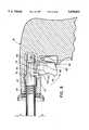
- FIG. 3Bis an enlarged view of the distal end of the trocar assembly illustrating the cutting blade
- FIG. 3Cis an enlarged view showing an alternate embodiment of the distal end of the trocar assembly
- FIG. 4is a side elevational view in partial cross-section of the trocar assembly of FIG. 2, illustrating the cutting blade in the deployed position;
- FIG. 4Ais an enlarged partial cross-sectional view of the distal end of the trocar assembly of FIG. 4, illustrating the cutting blade extending from the blade housing;
- FIG. 5is a side elevational view of an alternate embodiment of the cutting blade
- FIG. 6is a side elevational view of another alternative embodiment of the cutting blade
- FIGS. 7, 8 and 9are side elevational views of an alternative embodiment of the blade actuation mechanism
- FIG. 10is a rear plan view of a portion of the automatic release member of the blade actuating mechanism of FIG. 7;
- FIG. 11is a perspective view with parts separated of a portion of an alternative embodiment of the blade actuating mechanism
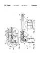
- FIG. 12is a side elevational view of the obturator assembly of FIG. 11;
- FIG. 13is an enlarged side elevational view of the blade actuating mechanism of FIG. 12, illustrating the trigger in a non-actuated position;
- FIG. 14is a sectional assembled view of a portion of the blade actuating mechanism of FIG. 11, illustrating the interconnection of the blade pusher arms to the actuating mechanism;
- FIG. 15is a side elevational view the obturator assembly of FIG. 11, illustrating partial actuation of the blade actuating mechanism with the blade in the non-deployed position;
- FIG. 16is an enlarged side elevational view of the blade actuating mechanism of FIG. 15;
- FIG. 17is an enlarged view of the distal end of the obturator assembly of FIG. 15, illustrating the dome-shaped blade housing;
- FIG. 18is a side elevational view of the obturator assembly of FIG. 11, illustrating actuation of the blade actuating mechanism and the blade in the deployed position;
- FIG. 19is an enlarged side elevational view of the blade actuating mechanism of FIG. 18.
- FIG. 20is an enlarged view of the distal end of the obturator assembly of FIG. 18, illustrating the dome-shaped blade housing and the blade in the deployed position.
- FIG. 1illustrates a trocar assembly 10 which typically includes two subassemblies, an obturator assembly 12 and a cannula assembly 14.
- the obturator assembly and the cannulaare configured to interfit during penetration and to be separated once penetration is completed.
- the term obturator assembly as used hereinrefers to the tissue penetrating assembly of the trocar assembly.
- obturator assembly 12includes housing 18 and a longitudinally extending obturator sleeve 20.
- obturator housing 18has two halves which are joined by adhesives or welding.
- the housingincludes barrel portion 22 and hand grip 24.
- the proximal end of obturator sleeve 20is secured within channel 26 of barrel portion 22 so that the obturator sleeve 20 extends outwardly from the obturator housing 18.
- Hand grip 24is provided for manual gripping to facilitate penetration of the body tissue.
- Obturator sleeve 20has a longitudinal bore 28 which extends between the proximal end and the distal end. The longitudinal bore 28 is configured and dimensioned to interact with the reciprocating blade and blade actuating assembly of the obturator assembly.
- the cutting portion of obturator assembly 12includes a cutting blade 34 connected to actuating assembly 36 and a blade housing 35.
- Blade housing 35is positioned at the distal end of obturator sleeve 20 and includes recess 37 configured to receive blade 34 when the blade is in the non-deployed position.
- Blade housing 35is provided to prevent inadvertent contact with the blade 34 by a user, as well as to support or stabilize the blade when the apparatus is not in use.
- Recess 37extends transverse to the longitudinal axis of the obturator.
- Blade 34extends at an angle to the longitudinal axis of the obturator.
- Blade 34includes a plurality of cutting surfaces 34a which have one end joined at an apex 34b, as shown in FIGS. 3A and 3B.
- the cutting surfaces as shownare two substantially straight edges angled towards each other.
- the bladesits in a recess 37 formed at the distal end of surface 37a which is composed of four substantially flat surfaces as shown.
- the blade 34'sits in a recess formed in conical surface 37b.
- the blade 34"may alternatively be arcuate in shape, as shown in FIG. 5 or the blade 34'" may be a solid triangular shape, as shown in FIG. 6.
- the blademay alternately be positioned in a recess formed at the distal end of the obturator itself.
- actuating assembly 36is provided to selectively control the blade 34, i.e. to move it 34 between a non-deployed position, shown in FIG. 3A, and a deployed position, shown in FIG. 4A.
- the blademoves with respect to the obturator and the actuating mechanism allows movement of the blade in any position. Consequently, movement of the blade is not dependent on the position of the obturator.
- the actuating assembly 36includes blade pusher arms 38 and 40, blade drive member 42, drive spring 44 and trigger 46.
- Blade 34can be formed as an integral piece with blade drive member 42 and/or blade arms 38 and 40.
- blade 34can be connected, such as by welding, to the distal end of blade pusher arms 38 and 40 which extend along the longitudinal axis of obturator sleeve 20 within slots 48 and 50 in the obturator sleeve, shown in FIG. 2B.
- the proximal end of blade pusher arms 38 and 40are secured within slots 52 and 54 of blade drive member 42, as shown.
- Blade drive member 42 and drive spring 44are positioned within channel 26 of obturator housing 18 so that drive spring 44 normally biases blade drive member 42 toward the proximal end of obturator housing 18.
- blade 34is normally biased to the proximal non-deployed position.
- Trigger 46is pivotally secured to obturator housing 18 via pin 56 so that camming surface 58 of trigger 46 engages the proximal end portion 42a of blade drive member 42.
- actuation of trigger 46i.e. movement of the trigger in the direction of the arrow in FIG. 4, causes camming surface 58 to engage blade drive member 42 and move the drive member distally within channel 26.
- Distal movement of drive member 42causes blade pusher arms 38 and 40 to move distally to move blade 34 distally to the deployed (extended) position.
- Release of trigger 46permits blade 34 to return to the non-deployed position in response to the action of drive spring 44 forcing blade drive member 42 proximally.
- the blade or cutting membercan also alternatively be movable in directions other than longitudinally as described above. For example, the blade can be movable in a direction transverse to the longitudinal axis, or the blade can vibrate.
- blade 34The movement of blade 34 between non-deployed and deployed positions can be seen by comparing FIGS. 3A and 4A. As shown in FIG. 3A, in the non-deployed position the blade 34 is at rest within recess 37 in blade housing 35. In the deployed position blade 34 is extended from recess 37 beyond the distal end of cannula assembly 14, as shown in FIG. 4A.
- FIGS. 7-10An alternative embodiment of the actuating assembly 36 is shown in FIGS. 7-10.
- an automatic release memberis associated with blade drive member 42 and trigger 46 and is provided to automatically return blade 34 to the non-deployed position after the blade is deployed. That is, the blade 34 returns to its initial undeployed position without requiring release of the trigger 46.
- trigger 46is pivotally secured to obturator housing 18 via pin 62 and lever 64 is pivotally secured to trigger 46 via lever pin 66.
- Spring 68biases trigger 46 distally.
- Lever spring 70is secured to trigger 46 at one end 70a and is positioned around pin 62, as shown.
- the biasing arm 70b of lever spring 70engages crossbar 72 of lever 64, shown in FIG. 10, and is provided to pivot lever 64 clockwise a predetermined angular distance, such as 12'.
- Lever bushing 74is secured to the upper portion of blade drive member 42, as shown, and is provided to engage lever 64.
- actuation of trigger 46i.e., movement of the trigger in the proximal direction, causes lever 64 to move blade drive member 42 distally to compress drive spring 44 and to advance blade 34 to the deployed position, shown in FIG. 4A.
- Lever 64pivots counter-clockwise with the actuation of trigger 46.
- a tactile or audible indicatormay be connected to the actuating assembly 36 to provide a surgeon with an indication that the blade is deployed.
- trigger 46may include a camming surface 80 which cams against rib 82 when the trigger is pivoted, as shown in FIGS. 7 and 8. Thus, providing the surgeon with a tactile indication that the blade is deployed.
- the actuating assembly 36includes a trigger 90 slidably positioned within channel 92 in housing 18 and movable between non-actuating and actuating positions.
- Spring 94is secured between housing 18 and trigger 90 so as to normally bias the trigger to the non-actuating position, shown in FIG. 12.
- Alignment fingers 96 and 98extend from trigger 90 into corresponding channels 100 and 102 within housing 18. Alignment fingers 96 and 98 are provided to maintain the alignment of trigger 90 within channel 92 of housing 18.
- Hammer latch 104is secured to trigger 90 and includes a latch release member, in the form of post 106.
- Post 106extends between the two housing halves and into corresponding channel 108 of each housing half, as shown in FIG. 11.
- Channel 108include a longitudinal portion 108a which permits the hammer latch 104 to engage the hammer, and a sloped portion 108b which causes hammer latch 104 to disengage from the hammer, as will be described in more detail below.
- the actuating assembly 36also includes blade drive members, such as hammer 110, bushing 112 and a pair of drive springs 114 and 116.
- blade drive memberssuch as hammer 110, bushing 112 and a pair of drive springs 114 and 116.
- the hammer, bushing and drive springsare coaxially aligned with obturator sleeve 20.
- Drive spring 114is positioned about obturator sleeve 20 within channel 118 of each housing half so that one end of the spring engages the housing and the other end engages the proximal end of hammer 110.
- Drive spring 114normally biases hammer 110 toward the distal end of the obturator assembly 12, indicated by arrow "A" in FIG. 13.
- the proximal end of bushing 112is positioned adjacent hammer 110 and the distal end of bushing 112 engages one end of drive spring 116.
- the other end of drive spring 116engages the housing 18, as shown.
- Finger 120 extending from bushing 112 into channel 122 within housing 18,is provided to limit the proximal and distal movement of the bushing 112 and thus the proximal and distal movement of blade 34.
- blade pusher arms 124 and 126are positioned in slots 128 and 130, respectively, within the obturator sleeve 20.
- the proximal end of each blade pusher armincludes fingers 132 extending outwardly therefrom. Fingers 132 are configured to slide within corresponding notches 134 in bushing 112 to releasably secure the blade pusher arms 124 and 126 to bushing 112, as shown in FIG. 14.
- actuating assembly 36The actuation of actuating assembly 36 is shown in FIGS. 15-20 and described below. Movement of trigger 90 in the proximal direction, shown by arrow "B" in FIGS. 15 and 16, causes hammer latch 104 to retract hammer 110 and compress drive spring 114 (i.e., the hammer latch moves the hammer to a cocked or armed position). Post 106 is within the longitudinal portion 108a of channel 108 and blade 34 continues to remain in the non-deployed (i.e., retracted) position within blade housing 35, as shown in FIG. 17. Further proximal movement of trigger 90 causes post 106 to move in a downward direction within the sloped portion 108b of channel 108, as shown in FIGS. 18 and 19.
- engagement of hammer 110 and bushing 112provides substantially instantaneous deployment and retraction of the blade so the blade remains exposed for a short period of time.
- the bladeis deployed and then retracted without further action of the user (i.e., without further movement of the trigger).
- the actuation assembly 36operates in a two step manner.
- trigger 90is moved proximally to cock hammer 110.
- further proximal movement of trigger 90causes the hammer 110 to automatically move distally to advance the blade 34 to the deployed position, and the blade is automatically returned to the non-deployed position under the force of drive spring 116.
- This two step mannerautomatically occurs upon fully squeezing the trigger 90.
- a tactile or audible indicatormay be connected to the actuating assembly 36 to provide a surgeon with an indication that the blade is deployed.
- cannula assembly 14includes cannula housing 76 and cannula sleeve 78 secured to the cannula housing 76 and extending outwardly therefrom.
- Obturator housing 18includes bushing 80 which is configured and dimensioned to interfit with the proximal end of cannula housing 76, so that obturator sleeve 20 coaxially aligns with cannula sleeve 78 when the two assemblies are interfitted.
- the cannula sleeve 78is adapted to remain in the body after penetration and subsequent removal of the obturator assembly 12 to allow insertion of appropriate endoscopic and/or laparoscopic instrumentation therethrough.
- a sealing member or systemmay be positioned therewithin which is adapted to receive the obturator assembly 12, as well as other endoscopic or laparoscopic surgical instruments.
- a suitable sealing systemutilizes a duckbill sealing member.
- a surgeonpositions the blade housing 35 against the body tissue and continuously moves blade 34 between the non-deployed and deployed positions, i.e., reciprocally moving blade 34 via actuating assembly 36. While reciprocating the blade 34, pressure is applied to hand grip 24 in the distal direction to penetrate the body tissue. The movement of blade 34 facilitates cutting of the body tissue, thus permitting the surgeon to apply relatively minimal pressure to hand grip 24 to penetrate the body tissue.
- An alternative method for penetrating the body tissueincorporates blunt penetration for soft tissue and cutting penetration for thicker tissue.
- the surgeonpositions the blade housing 35 against body tissue and applies pressure to hand grip 24 to bluntly penetrate soft body tissue.
- thicker tissuesuch as muscle
- the bladecan be deployed to penetrate (cut through) this thick tissue, then retracted to provide blunt penetration until thick tissue is again encountered, where once again the blade can be deployed.
- the obturator assembly 12After penetration into the body cavity, the obturator assembly 12 is removed from the cannula assembly 14, leaving the cannula assembly 14 in the body for insertion of desired instrumentation therethrough.
Landscapes
- Health & Medical Sciences (AREA)
- Surgery (AREA)
- Life Sciences & Earth Sciences (AREA)
- Biomedical Technology (AREA)
- Nuclear Medicine, Radiotherapy & Molecular Imaging (AREA)
- Engineering & Computer Science (AREA)
- Pathology (AREA)
- Heart & Thoracic Surgery (AREA)
- Medical Informatics (AREA)
- Molecular Biology (AREA)
- Animal Behavior & Ethology (AREA)
- General Health & Medical Sciences (AREA)
- Public Health (AREA)
- Veterinary Medicine (AREA)
- Surgical Instruments (AREA)
Abstract
Description
This is a continuation of application Ser. No. 08/322,884, filed on Oct. 13, 1994, now abandoned which is a continuation-in-part of U.S. application Ser. No. 08/249,707, filed May 26, 1994, which is a continuation-in-part of U.S. application Ser. No. 08/132,403, filed Oct. 6, 1993, now U.S. Pat. No. 5,467,762 issued Nov. 21, 1995, which is a continuation-in-part of U.S. application Ser. No. 08/120,489, filed Sep. 13, 1993 now U.S. Pat. No. 5,441,041, issued Aug. 15, 1995.
1. Technical Field
A trocar assembly having a movable blade for penetrating body tissue is provided. More particularly, the trocar assembly has a reciprocating blade which may be selectively deployed to penetrate the peritoneum or other body tissue.
2. Description of Related Art
Endoscopic and laparoscopic surgical procedures, that is, surgical procedures performed through tubular sleeves or cannulas, have been utilized for many years. In endoscopic procedures, surgery is performed in any hollow viscus of the body through a small incision or through narrow endoscopic tubes (cannulas) inserted through small entrance wounds in the skin. In laparoscopic procedures surgery is performed in the interior of the abdomen. Initially, such surgical procedures were primarily diagnostic in nature. More recently, endoscopic and laparoscopic surgical techniques and instrumentation have advanced to permit surgeons to perform increasingly complex and innovative surgical procedures.
Endoscopic and laparoscopic procedures often require the surgeon to act on organs, tissues and vessels far removed from the incision, thereby requiring that any instruments to be used in such procedures be of sufficient size and length to permit remote operation. Moreover, such procedures generally utilize instrumentation that is internally sealed to inhibit gases from entering or exiting the body through the laparoscopic or endoscopic incision. This is particularly true in surgical procedures in which the surgical region is insufflated.
Typically, after the surgical region is insufflated, trocars are used to puncture the body cavity and include a cannula which remains in place for use during the endoscopic or laparoscopic procedures. Heretofore, trocars used during such procedures include a protective tube and a styler having a sharp tip which is positioned coaxially within the protective tube to protect a patient or surgeon from inadvertent contact with the tip. An example of a known trocar is described in commonly assigned, U.S. Pat. No. 4,601,710 to Moll. Most currently used trocars require the surgeon to apply pressure to the trocar to cause the sharp tip to penetrate the body tissue. The amount of pressure required often varies depending on, for example, the thickness of the tissue being penetrated.
The trocar assembly of the present invention provides an alternative technique for penetrating the body tissue by providing a reciprocating blade to incise body tissue while the trocar penetrates the body tissue.
A surgical apparatus for penetrating body tissue is disclosed. In particular, a trocar assembly is provided having a movable blade at a distal end portion which cuts or severs the body tissue during penetration. The trocar assembly includes a cannula, an obturator having a proximal portion and a distal portion and which is configured for insertion into the cannula. A body tissue cutting member is mounted to the distal portion of the obturator and is movable between deployed and non-deployed positions. An actuating mechanism is also provided to move the tissue cutting member between the deployed and non-deployed positions independent of the position of the obturator.
In one embodiment, the actuating mechanism includes a pair of pusher members each having a proximal portion connected to a drive mechanism and a distal portion connected to the tissue cutting member. A trigger is operatively connected to the drive mechanism for longitudinally moving the pair of pusher members. The pair of pusher members are associated with the obturator and longitudinally movable relative to the obturator.
To achieve the longitudinal movement of the pusher members, the trigger may be pivotally mounted to an obturator housing such that pivotal movement of the trigger is translated to longitudinal movement of the pusher members. In an alternative embodiment, the trigger is movable between first and second predetermined positions such that movement of the trigger to the first predetermined position causes the pusher members to move the tissue cutting member to the deployed position, and movement of the trigger to the second position causes the at least one pusher member to move the tissue cutting member to the non-deployed position.
Generally, the tissue cutting member is positioned within a recess in the obturator when in the non-deployed position and extends from the obturator when deployed. Alternatively, a housing may be positioned at the distal portion of the obturator to receive the tissue cutting member when in the non-deployed position. Preferably, the tissue cutting member is a blade having an apex. However, other blade configurations are contemplated, such as an arcuate shaped blade.
Preferred embodiments are described hereinbelow with reference to the drawings wherein:
FIG. 1 is a perspective view with parts separated of a trocar assembly with a movable blade;
FIG. 2 is a side elevational view with parts separated of the trocar assembly with a movable blade;
FIG. 2A is an enlarged perspective view of the movable cutting blade and a blade housing;
FIG. 2B is an enlarged cross-sectional view of an obturator sleeve shown in FIG. 2;
FIG. 3 is a side elevational view in partial cross-section of the trocar assembly of FIG. 2, illustrating the cutting blade in the non-deployed position within the blade housing;
FIG. 3A is an enlarged partial cross-sectional view of the distal end of the trocar assembly of FIG. 3, illustrating the cutting blade recessed within the blade housing;
FIG. 3B is an enlarged view of the distal end of the trocar assembly illustrating the cutting blade;
FIG. 3C is an enlarged view showing an alternate embodiment of the distal end of the trocar assembly;
FIG. 4 is a side elevational view in partial cross-section of the trocar assembly of FIG. 2, illustrating the cutting blade in the deployed position;
FIG. 4A is an enlarged partial cross-sectional view of the distal end of the trocar assembly of FIG. 4, illustrating the cutting blade extending from the blade housing;
FIG. 5 is a side elevational view of an alternate embodiment of the cutting blade;
FIG. 6 is a side elevational view of another alternative embodiment of the cutting blade;
FIGS. 7, 8 and 9 are side elevational views of an alternative embodiment of the blade actuation mechanism;
FIG. 10 is a rear plan view of a portion of the automatic release member of the blade actuating mechanism of FIG. 7;
FIG. 11 is a perspective view with parts separated of a portion of an alternative embodiment of the blade actuating mechanism;
FIG. 12 is a side elevational view of the obturator assembly of FIG. 11;
FIG. 13 is an enlarged side elevational view of the blade actuating mechanism of FIG. 12, illustrating the trigger in a non-actuated position;
FIG. 14 is a sectional assembled view of a portion of the blade actuating mechanism of FIG. 11, illustrating the interconnection of the blade pusher arms to the actuating mechanism;
FIG. 15 is a side elevational view the obturator assembly of FIG. 11, illustrating partial actuation of the blade actuating mechanism with the blade in the non-deployed position;
FIG. 16 is an enlarged side elevational view of the blade actuating mechanism of FIG. 15;
FIG. 17 is an enlarged view of the distal end of the obturator assembly of FIG. 15, illustrating the dome-shaped blade housing;
FIG. 18 is a side elevational view of the obturator assembly of FIG. 11, illustrating actuation of the blade actuating mechanism and the blade in the deployed position;
FIG. 19 is an enlarged side elevational view of the blade actuating mechanism of FIG. 18; and
FIG. 20 is an enlarged view of the distal end of the obturator assembly of FIG. 18, illustrating the dome-shaped blade housing and the blade in the deployed position.
The trocar assembly described herein is provided to reduce the pressure required to penetrate body tissue during endoscopic and laparoscopic surgical procedures. FIG. 1 illustrates atrocar assembly 10 which typically includes two subassemblies, anobturator assembly 12 and acannula assembly 14. The obturator assembly and the cannula are configured to interfit during penetration and to be separated once penetration is completed. The term obturator assembly as used herein refers to the tissue penetrating assembly of the trocar assembly.
Referring to FIGS. 1 and 2,obturator assembly 12 includeshousing 18 and a longitudinally extendingobturator sleeve 20. Preferably,obturator housing 18 has two halves which are joined by adhesives or welding. The housing includesbarrel portion 22 andhand grip 24. The proximal end ofobturator sleeve 20 is secured withinchannel 26 ofbarrel portion 22 so that theobturator sleeve 20 extends outwardly from theobturator housing 18.Hand grip 24 is provided for manual gripping to facilitate penetration of the body tissue.Obturator sleeve 20 has alongitudinal bore 28 which extends between the proximal end and the distal end. Thelongitudinal bore 28 is configured and dimensioned to interact with the reciprocating blade and blade actuating assembly of the obturator assembly.
Referring to FIGS. 3 and 4, the cutting portion ofobturator assembly 12 includes acutting blade 34 connected to actuatingassembly 36 and ablade housing 35.Blade housing 35 is positioned at the distal end ofobturator sleeve 20 and includesrecess 37 configured to receiveblade 34 when the blade is in the non-deployed position.Blade housing 35 is provided to prevent inadvertent contact with theblade 34 by a user, as well as to support or stabilize the blade when the apparatus is not in use.Recess 37 extends transverse to the longitudinal axis of the obturator.
The blade extends at an angle to the longitudinal axis of the obturator.Blade 34 includes a plurality of cuttingsurfaces 34a which have one end joined at an apex 34b, as shown in FIGS. 3A and 3B. The cutting surfaces as shown, are two substantially straight edges angled towards each other. The blade sits in arecess 37 formed at the distal end ofsurface 37a which is composed of four substantially flat surfaces as shown. In the alternate embodiment of FIG. 3C, the blade 34' sits in a recess formed in conical surface 37b. Theblade 34" may alternatively be arcuate in shape, as shown in FIG. 5 or the blade 34'" may be a solid triangular shape, as shown in FIG. 6. The blade may alternately be positioned in a recess formed at the distal end of the obturator itself.
Referring again to FIG. 2, actuatingassembly 36 is provided to selectively control theblade 34, i.e. to move it 34 between a non-deployed position, shown in FIG. 3A, and a deployed position, shown in FIG. 4A. As is apparent, the blade moves with respect to the obturator and the actuating mechanism allows movement of the blade in any position. Consequently, movement of the blade is not dependent on the position of the obturator. In one embodiment, the actuatingassembly 36 includesblade pusher arms blade drive member 42,drive spring 44 andtrigger 46.Blade 34 can be formed as an integral piece withblade drive member 42 and/orblade arms blade 34 can be connected, such as by welding, to the distal end ofblade pusher arms obturator sleeve 20 withinslots blade pusher arms slots 52 and 54 ofblade drive member 42, as shown.Blade drive member 42 and drivespring 44 are positioned withinchannel 26 ofobturator housing 18 so thatdrive spring 44 normally biasesblade drive member 42 toward the proximal end ofobturator housing 18. As a result,blade 34 is normally biased to the proximal non-deployed position.
The movement ofblade 34 between non-deployed and deployed positions can be seen by comparing FIGS. 3A and 4A. As shown in FIG. 3A, in the non-deployed position theblade 34 is at rest withinrecess 37 inblade housing 35. In the deployedposition blade 34 is extended fromrecess 37 beyond the distal end ofcannula assembly 14, as shown in FIG. 4A.
An alternative embodiment of the actuatingassembly 36 is shown in FIGS. 7-10. In this embodiment, an automatic release member is associated withblade drive member 42 andtrigger 46 and is provided to automatically returnblade 34 to the non-deployed position after the blade is deployed. That is, theblade 34 returns to its initial undeployed position without requiring release of thetrigger 46.
Referring to FIG. 7, trigger 46 is pivotally secured toobturator housing 18 viapin 62 andlever 64 is pivotally secured to trigger 46 vialever pin 66.Spring 68 biases trigger 46 distally.Lever spring 70 is secured to trigger 46 at oneend 70a and is positioned aroundpin 62, as shown. The biasing arm 70b oflever spring 70 engagescrossbar 72 oflever 64, shown in FIG. 10, and is provided to pivotlever 64 clockwise a predetermined angular distance, such as 12'.Lever bushing 74 is secured to the upper portion ofblade drive member 42, as shown, and is provided to engagelever 64. Whentrigger 46 is in the armed position, i.e., trigger 46 is ready for actuation,lever 64 is biased upward bylever spring 70 so that the upper portion oflever 64 engageslever bushing 74, as shown in FIG. 7.
Referring to FIG. 8, actuation oftrigger 46, i.e., movement of the trigger in the proximal direction, causeslever 64 to moveblade drive member 42 distally to compressdrive spring 44 and to advanceblade 34 to the deployed position, shown in FIG. 4A.Lever 64 pivots counter-clockwise with the actuation oftrigger 46. A tactile or audible indicator may be connected to theactuating assembly 36 to provide a surgeon with an indication that the blade is deployed. For example, trigger 46 may include acamming surface 80 which cams againstrib 82 when the trigger is pivoted, as shown in FIGS. 7 and 8. Thus, providing the surgeon with a tactile indication that the blade is deployed.
Referring now to FIG. 9, further movement or actuation oftrigger 46 in the proximal direction causeslever 64 to continue to pivot counter-clockwise so that the portion oflever 64 engaginglever bushing 74 disengages therefrom. As a result,blade drive member 42 moves proximally under the action ofdrive spring 44 to moveblade 34 to the non-deployed position withinblade housing 35, shown in FIG. 3. Tore-arm lever 64,trigger 46 is released.Trigger 46 is consequently forced clockwise byspring 68 causinglever 64 to pivot clockwisepast bushing 74 as it is pulled slightly proximally by such clockwise movement oftrigger 46. Whentrigger 46 returns to the original, i.e. actuation, position of FIG. 7,lever spring 70biases lever 64 clockwise to a position which permits engagement withlever bushing 74.
Referring now to FIGS. 11, 12 and 13, another alternative embodiment of actuatingassembly 36 is shown. This actuating assembly is shown in conjunction with a dome-shaped tip and arcuate blade. However, any of the actuating assemblies can be used with various shaped blades and tips, such as those shown in FIGS. 3B and 3C. In this embodiment of FIGS. 11-13, the actuatingassembly 36 includes atrigger 90 slidably positioned withinchannel 92 inhousing 18 and movable between non-actuating and actuating positions.Spring 94 is secured betweenhousing 18 and trigger 90 so as to normally bias the trigger to the non-actuating position, shown in FIG. 12.Alignment fingers trigger 90 into correspondingchannels housing 18.Alignment fingers trigger 90 withinchannel 92 ofhousing 18.
Referring again to FIGS. 11 and 14, the actuatingassembly 36 also includes blade drive members, such ashammer 110,bushing 112 and a pair of drive springs 114 and 116. As shown in FIG. 14, the hammer, bushing and drive springs are coaxially aligned withobturator sleeve 20.Drive spring 114 is positioned aboutobturator sleeve 20 withinchannel 118 of each housing half so that one end of the spring engages the housing and the other end engages the proximal end ofhammer 110.Drive spring 114 normally biases hammer 110 toward the distal end of theobturator assembly 12, indicated by arrow "A" in FIG. 13. The proximal end ofbushing 112 is positionedadjacent hammer 110 and the distal end ofbushing 112 engages one end ofdrive spring 116. The other end ofdrive spring 116 engages thehousing 18, as shown.Finger 120 extending from bushing 112 intochannel 122 withinhousing 18, is provided to limit the proximal and distal movement of thebushing 112 and thus the proximal and distal movement ofblade 34.
Referring again to FIGS. 11 and 14,blade pusher arms slots obturator sleeve 20. The proximal end of each blade pusher arm includesfingers 132 extending outwardly therefrom.Fingers 132 are configured to slide withincorresponding notches 134 inbushing 112 to releasably secure theblade pusher arms bushing 112, as shown in FIG. 14.
The actuation of actuatingassembly 36 is shown in FIGS. 15-20 and described below. Movement oftrigger 90 in the proximal direction, shown by arrow "B" in FIGS. 15 and 16, causes hammerlatch 104 to retracthammer 110 and compress drive spring 114 (i.e., the hammer latch moves the hammer to a cocked or armed position).Post 106 is within the longitudinal portion 108a ofchannel 108 andblade 34 continues to remain in the non-deployed (i.e., retracted) position withinblade housing 35, as shown in FIG. 17. Further proximal movement oftrigger 90 causes post 106 to move in a downward direction within the sloped portion 108b ofchannel 108, as shown in FIGS. 18 and 19. Downward movement ofpost 106 causes hammerlatch 104 to disengage fromhammer 110 so thathammer 110 is thrusted distally (i.e., in the direction of arrow "C") bydrive spring 114. Ashammer 110 moves distally, the hammer engagesbushing 112 and thrusts the bushing distally so as to moveblade 34 to the deployed (i.e., exposed) position, shown in FIG. 20. Distal movement ofbushing 112 also compressdrive spring 116 and when the biasing force ofdrive spring 116 exceeds the compression force exerted by thehammer 110,drive spring 116 automatically biases bushing 112 proximally so thatblade 34 is automatically returned to the non-deployed position. Thus, engagement ofhammer 110 andbushing 112 provides substantially instantaneous deployment and retraction of the blade so the blade remains exposed for a short period of time. Thus, once the trigger is pulled to a predetermined position, the blade is deployed and then retracted without further action of the user (i.e., without further movement of the trigger).
In the configuration described, theactuation assembly 36 operates in a two step manner. In the first step, trigger 90 is moved proximally to cockhammer 110. In the second step, further proximal movement oftrigger 90 causes thehammer 110 to automatically move distally to advance theblade 34 to the deployed position, and the blade is automatically returned to the non-deployed position under the force ofdrive spring 116. This two step manner automatically occurs upon fully squeezing thetrigger 90. As noted above, a tactile or audible indicator may be connected to theactuating assembly 36 to provide a surgeon with an indication that the blade is deployed.
Referring again to FIG. 1,cannula assembly 14 includescannula housing 76 andcannula sleeve 78 secured to thecannula housing 76 and extending outwardly therefrom.Obturator housing 18 includesbushing 80 which is configured and dimensioned to interfit with the proximal end ofcannula housing 76, so thatobturator sleeve 20 coaxially aligns withcannula sleeve 78 when the two assemblies are interfitted. Thecannula sleeve 78 is adapted to remain in the body after penetration and subsequent removal of theobturator assembly 12 to allow insertion of appropriate endoscopic and/or laparoscopic instrumentation therethrough.
To maintain a gas tight seal within the cannula housing, a sealing member or system may be positioned therewithin which is adapted to receive theobturator assembly 12, as well as other endoscopic or laparoscopic surgical instruments. One example of a suitable sealing system utilizes a duckbill sealing member. A more detailed description of an exemplary cannula assembly and sealing system is found in U.S. Pat. No. 5,180,373 issued Jan. 19, 1993, which is incorporated herein by reference.
To penetrate body tissue, a surgeon positions theblade housing 35 against the body tissue and continuously movesblade 34 between the non-deployed and deployed positions, i.e., reciprocally movingblade 34 via actuatingassembly 36. While reciprocating theblade 34, pressure is applied tohand grip 24 in the distal direction to penetrate the body tissue. The movement ofblade 34 facilitates cutting of the body tissue, thus permitting the surgeon to apply relatively minimal pressure to handgrip 24 to penetrate the body tissue.
Once the surgeon penetrates the body tissue, the surgeon releases trigger 46 to permitblade 34 to return to the non-deployed position and discontinues application of pressure to handgrip 24. According to the embodiments of FIGS. 7-10 and 11-20 for the trigger actuating assembly, once thetrigger 46 is fully actuated,blade 34 automatically returns to the non-deployed position and release oftrigger 46 re-arms the automatic release member.
An alternative method for penetrating the body tissue incorporates blunt penetration for soft tissue and cutting penetration for thicker tissue. For this technique, the surgeon positions theblade housing 35 against body tissue and applies pressure to handgrip 24 to bluntly penetrate soft body tissue. When thicker tissue, such as muscle, is encountered, the blade can be deployed to penetrate (cut through) this thick tissue, then retracted to provide blunt penetration until thick tissue is again encountered, where once again the blade can be deployed.
After penetration into the body cavity, theobturator assembly 12 is removed from thecannula assembly 14, leaving thecannula assembly 14 in the body for insertion of desired instrumentation therethrough.
It will be understood that various modifications can be made to the embodiments herein disclosed without departing from the spirit and scope thereof. For example, various diameters for the cannula assembly, the obturator assembly, as well as various diameter endoscopes are contemplated. Also, various modifications may be made in the configuration of the parts. Therefore, the above description should not be construed as limiting, but merely as exemplifications of preferred embodiments thereof.
Claims (22)
1. A surgical apparatus comprising:
a cannula;
an obturator configured for insertion into the cannula, the obturator having a proximal portion and a distal portion;
a tissue cutting member mounted to the distal portion of the obturator and movable between deployed and non-deployed positions; and
an actuating mechanism operatively associated with the tissue cutting member, the actuating mechanism being selectively controllable for moving the tissue cutting member between the deployed and non-deployed positions independent of the position of the obturator;
wherein movement of the actuating mechanism to a cutting member deployment position causes the cutting member to move to the deployed position, the actuating mechanism at the cutting member deployment position also automatically retracts the cutting member to the non-deployed position, wherein the actuating mechanism cannot maintain the cutting member in the deployed position as each deployment of the cutting member causes automatic retraction of the cutting member.
2. The surgical apparatus according to claim 1, wherein the actuating mechanism includes a trigger operatively associated with the cutting member.
3. The surgical apparatus according to claim 1, wherein the actuating mechanism comprises:
at least one pusher member having a proximal portion and a distal portion connected to the tissue cutting member, the at least one pusher member being operatively associated with the obturator and longitudinally movable relative thereto;
a drive mechanism connected to the proximal portion of the at least one pusher member; and
a trigger operatively connected to the drive mechanism for longitudinally moving the at least one pusher member.
4. The surgical apparatus according to claim 3, wherein the trigger is movable between first and second positions such that movement of the trigger to the first position causes the at least one pusher member to move the tissue cutting member to the deployed position, and causes the at least one pusher member to move the tissue cutting member to the non-deployed position.
5. The surgical apparatus according to claim 1, wherein in the non-deployed position, the tissue cutting member is positioned within a recess in the obturator.
6. The surgical apparatus according to claim 1 further comprising a housing positioned at the distal portion of the obturator and configured to receive the tissue cutting member when in the non-deployed position.
7. The surgical apparatus according to claim 1, wherein the tissue cutting member comprises a blade having an apex.
8. The surgical apparatus according to claim 1, wherein the tissue cutting member comprises an arcuate shaped blade.
9. The surgical apparatus according to claim 1, wherein the cutting member comprises a cutting blade.
10. The surgical apparatus according to claim 9, wherein the actuating mechanism includes a trigger operatively associated with the cutting member.
11. The surgical apparatus according to claim 10, wherein movement of the trigger in a first direction moves the blade to the deployed position and then moves the blade to the non-deployed position.
12. The surgical apparatus according to claim 1, further comprising a first spring for moving a drive hammer in a distal direction to move the cutting member to the deployed position and a second spring for causing movement of the cutting member to the non-deployed position.
13. The surgical apparatus according to claim 12, further comprising a bushing engagable by the drive hammer to move the cutting member to the deployed position, and wherein the second spring moves the bushing proximally to move the cutting member to the non-deployed position.
14. A surgical apparatus comprising:
a cannula;
an obturator configured for insertion into the cannula, the obturator having a proximal portion and a distal portion and defining a longitudinal axis;
a blade mounted adjacent the distal potion of the obturator and extending at an angle with respect to the longitudinal axis of the obturator;
an actuating mechanism having a proximal portion associated with the proximal portion of the obturator and a distal portion operatively connected to the blade, the actuating mechanism configured to move the blade between a retracted position within the distal portion of the obturator and an extended position extending from the obturator
wherein movement of the actuating mechanism to a blade deployment position causes the blade to move to the extended position, the actuating mechanism at the blade deployment position also automatically retracts the blade to the retracted position, wherein the actuating mechanism cannot maintain the cutting member in the extended position as each deployment of the cutting member causes automatic retraction of the cutting member.
15. The surgical apparatus according to claim 14, wherein the actuating mechanism is actuable independent of the position of the obturator.
16. The surgical apparatus according to claim 14, wherein the actuating mechanism includes a trigger movable in a first direction to move the blade to the extended position and includes release structure to automatically return the blade to the retracted position.
17. The surgical apparatus according to claim 14, wherein the obturator includes a transverse recess to receive the blade in the retracted position.
18. The surgical apparatus according to claim 17, wherein the blade has two angled edges terminating at an apex.
19. The surgical apparatus according to claim 17, wherein the blade is arcuate in configuration.
20. The surgical apparatus according to claim 14, further comprising first and second longitudinally extending pusher arms operatively connected to the blade and the trigger for moving the blade between the extended and retracted positions.
21. The surgical apparatus according to claim 14, further comprising a first spring for moving a drive hammer in a distal direction to move the blade to the extended position and a second spring for causing movement of the blade to the retracted position.
22. The surgical apparatus according to claim 21, further comprising a bushing engagable by the drive hammer to move the blade to the extended position, and wherein the second spring moves the blade to the retracted position.
Priority Applications (1)
| Application Number | Priority Date | Filing Date | Title |
|---|---|---|---|
| US08/715,305US5690664A (en) | 1993-09-13 | 1996-09-18 | Trocar having movable blade |
Applications Claiming Priority (5)
| Application Number | Priority Date | Filing Date | Title |
|---|---|---|---|
| US08/120,489US5441041A (en) | 1993-09-13 | 1993-09-13 | Optical trocar |
| US08/132,403US5467762A (en) | 1993-09-13 | 1993-10-06 | Optical trocar |
| US24970794A | 1994-05-26 | 1994-05-26 | |
| US32288494A | 1994-10-13 | 1994-10-13 | |
| US08/715,305US5690664A (en) | 1993-09-13 | 1996-09-18 | Trocar having movable blade |
Related Parent Applications (1)
| Application Number | Title | Priority Date | Filing Date |
|---|---|---|---|
| US32288494AContinuation | 1993-09-13 | 1994-10-13 |
Publications (1)
| Publication Number | Publication Date |
|---|---|
| US5690664Atrue US5690664A (en) | 1997-11-25 |
Family
ID=27494312
Family Applications (1)
| Application Number | Title | Priority Date | Filing Date |
|---|---|---|---|
| US08/715,305Expired - LifetimeUS5690664A (en) | 1993-09-13 | 1996-09-18 | Trocar having movable blade |
Country Status (1)
| Country | Link |
|---|---|
| US (1) | US5690664A (en) |
Cited By (49)
| Publication number | Priority date | Publication date | Assignee | Title |
|---|---|---|---|---|
| US6030402A (en)* | 1998-04-23 | 2000-02-29 | Thompson; Ronald J. | Apparatus and methods for the penetration of tissue, and the creation of an opening therein |
| US6039748A (en)* | 1997-08-05 | 2000-03-21 | Femrx, Inc. | Disposable laparoscopic morcellator |
| US6056766A (en)* | 1998-06-09 | 2000-05-02 | Thompson; Ronald J. | Stabilized trocar, and method of using same |
| US6447527B1 (en) | 1998-04-23 | 2002-09-10 | Ronald J. Thompson | Apparatus and methods for the penetration of tissue |
| US6602267B2 (en)* | 2001-10-17 | 2003-08-05 | Medcanica, Inc. | Articulable and reciprocable surgical knife |
| US20030158566A1 (en)* | 2001-11-15 | 2003-08-21 | Expanding Concepts, L.L.C. | Percutaneous cellulite removal system |
| US20040006379A1 (en)* | 2000-10-06 | 2004-01-08 | Expanding Concepts, L.L.C. | Epidural thermal posterior annuloplasty |
| US20040162572A1 (en)* | 2003-02-13 | 2004-08-19 | Sauer Jude S. | Instrument for surgically cutting tissue and method of use |
| USD499484S1 (en) | 2003-08-12 | 2004-12-07 | Erblan Surgical, Inc. | Trocar seal-valve |
| USD517694S1 (en) | 2003-08-12 | 2006-03-21 | Erblan Surgical, Inc | Tip portion of an infusor |
| USD518177S1 (en) | 2002-03-08 | 2006-03-28 | Erblan Surgical, Inc. | Safety trocar with progressive cutting tip guards and gas jet tissue deflector |
| US20060116704A1 (en)* | 2004-07-15 | 2006-06-01 | Boston Scientific Scimed, Inc. | Tissue tract lancet |
| US20070005087A1 (en)* | 2005-06-30 | 2007-01-04 | Smith Robert C | Thin bladed obturator with curved surfaces |
| US20070016237A1 (en)* | 2005-06-30 | 2007-01-18 | Smith Robert C | Trocar assembly with rotatable obturator housing |
| US20080086160A1 (en)* | 2006-10-06 | 2008-04-10 | Surgiquest, Incorporated | Visualization trocar |
| US20080319467A1 (en)* | 2007-06-22 | 2008-12-25 | Thomas Wenchell | Thin bladed obturator |
| US20090082735A1 (en)* | 2006-03-27 | 2009-03-26 | Aesculap Ag | Surgical sealing element, surgical seal, and surgical sealing system |
| US20090093833A1 (en)* | 2007-10-05 | 2009-04-09 | Tyco Healthcare Group Lp | Bladeless obturator for use in a surgical trocar assembly |
| US20100010446A1 (en)* | 2008-07-09 | 2010-01-14 | Aesculap Ag | Surgical sealing element holder for holding a surgical sealing element and surgical sealing system |
| US20100016799A1 (en)* | 2008-07-09 | 2010-01-21 | Aesculap Ag | Surgical protection device for a surgical sealing element and surgical sealing system |
| US20100023042A1 (en)* | 2007-02-02 | 2010-01-28 | Synthes (U.S.A.) | Tunnel Tool for Soft Tissue |
| US20100063450A1 (en)* | 2007-04-18 | 2010-03-11 | Tyco Healthcare Group Lp | Trocar assembly with obturator dissector |
| US20100076478A1 (en)* | 2006-12-15 | 2010-03-25 | Smith Robert C | Trocar assembly with obturator design |
| US20100324486A1 (en)* | 2007-02-20 | 2010-12-23 | Smith Robert C | Surgical apparatus with annular penetrator |
| US20110152910A1 (en)* | 2009-12-17 | 2011-06-23 | Tyco Healthcare Group Lp | Visual obturator with tip openings |
| USD663838S1 (en) | 2007-10-05 | 2012-07-17 | Surgiquest, Inc. | Visualization trocar |
| USD667954S1 (en) | 2007-10-05 | 2012-09-25 | Surgiquest, Inc. | Visualization trocar |
| US8430851B2 (en) | 2005-10-14 | 2013-04-30 | Applied Medical Resources Corporation | Surgical access port |
| EP2142116A4 (en)* | 2007-04-17 | 2013-07-17 | Covidien Lp | VISUAL SHUTTER WITH HANDLE |
| US8795223B2 (en) | 2011-03-08 | 2014-08-05 | Surgiquest, Inc. | Trocar assembly with pneumatic sealing |
| US20140358070A1 (en) | 2007-04-13 | 2014-12-04 | Surgiquest, Inc. | System and method for improved gas recirculation in surgical trocars with pneumatic sealing |
| US8956376B2 (en) | 2011-06-30 | 2015-02-17 | The Spectranetics Corporation | Reentry catheter and method thereof |
| US8961552B2 (en) | 2010-09-21 | 2015-02-24 | Covidien Lp | Bladeless obturators and bladeless obturator members |
| US8979883B2 (en) | 2009-12-17 | 2015-03-17 | Covidien Lp | Obturator tip |
| US8998936B2 (en) | 2011-06-30 | 2015-04-07 | The Spectranetics Corporation | Reentry catheter and method thereof |
| US9271752B2 (en) | 2013-03-13 | 2016-03-01 | Swan Valley Medical Incorporated | Method and apparatus for placing a cannula in a bladder |
| US9814862B2 (en) | 2011-06-30 | 2017-11-14 | The Spectranetics Corporation | Reentry catheter and method thereof |
| US10159402B2 (en) | 2005-04-12 | 2018-12-25 | Covidien Lp | Optical trocar with scope holding assembly |
| US10357272B2 (en) | 2014-09-18 | 2019-07-23 | Mayo Foundation For Medical Education And Research | Soft tissue cutting device and methods of use |
| US10369303B2 (en) | 2003-04-08 | 2019-08-06 | Conmed Corporation | Trocar assembly with pneumatic sealing |
| US20200178769A1 (en)* | 2013-03-15 | 2020-06-11 | DePuy Synthes Products, Inc. | Viewing trocar with integrated prism for use with angled endoscope |
| US10864055B2 (en) | 2017-10-13 | 2020-12-15 | Sonex Health, Inc. | Tray for a soft tissue cutting device and methods of use |
| USD981563S1 (en)* | 2019-10-11 | 2023-03-21 | Aok Innovations, Llc | Chest tube insertion aid and handle assembly |
| USD989961S1 (en) | 2021-04-30 | 2023-06-20 | Sonex Health, Inc. | Soft tissue cutting device |
| US11937845B2 (en) | 2019-01-11 | 2024-03-26 | Mayo Foundation For Medical Education And Research | Micro-invasive surgical device and methods of use |
| US11963692B2 (en) | 2021-04-30 | 2024-04-23 | Aok Innovations, Llc | Body cavity access device |
| US12004767B2 (en) | 2021-01-08 | 2024-06-11 | Sonex Health, Inc. | Surgical cutting device for ultrasonic guided soft tissue surgery |
| US12251122B2 (en) | 2021-04-30 | 2025-03-18 | Sonex Health, Inc. | Cutting device for trigger finger and other soft tissues |
| US12426939B2 (en) | 2019-05-29 | 2025-09-30 | Mayo Foundation For Medical Education And Research | Micro-invasive surgical device and methods of use |
Citations (45)
| Publication number | Priority date | Publication date | Assignee | Title |
|---|---|---|---|---|
| US1380447A (en)* | 1919-06-14 | 1921-06-07 | Protein Products Corp | Trocar |
| US2699770A (en)* | 1951-05-11 | 1955-01-18 | Centre Nat Rech Scient | Endoscope |
| US3538916A (en)* | 1968-12-19 | 1970-11-10 | Joseph S Wiles | Injection pistol |
| US3762416A (en)* | 1970-06-03 | 1973-10-02 | Nat Res Dev | Artery entry tool |
| US3809095A (en)* | 1969-10-15 | 1974-05-07 | H Cimber | Aspirator needle injector |
| US3915169A (en)* | 1974-11-14 | 1975-10-28 | George Mcguire | Surgical knife having malleable shank |
| SU537677A1 (en)* | 1975-06-27 | 1976-12-05 | Trocar | |
| US4210146A (en)* | 1978-06-01 | 1980-07-01 | Anton Banko | Surgical instrument with flexible blade |
| US4220155A (en)* | 1978-05-11 | 1980-09-02 | Colorado State University Research Foundation | Apparatus for spaying large animals |
| US4254762A (en)* | 1979-10-23 | 1981-03-10 | Inbae Yoon | Safety endoscope system |
| US4256119A (en)* | 1979-09-17 | 1981-03-17 | Gauthier Industries, Inc. | Biopsy needle |
| US4411653A (en)* | 1982-01-28 | 1983-10-25 | Razi M Dean | Cannula introducer |
| US4461305A (en)* | 1981-09-04 | 1984-07-24 | Cibley Leonard J | Automated biopsy device |
| US4516575A (en)* | 1982-06-03 | 1985-05-14 | Coopervision, Inc. | Surgical scalpel |
| US4539976A (en)* | 1984-02-08 | 1985-09-10 | Sharpe Jewett M | Endoscopic surgical instrument |
| US4559041A (en)* | 1984-06-25 | 1985-12-17 | Razi M Dean | Cannula introducers |
| US4570632A (en)* | 1984-03-16 | 1986-02-18 | Woods Randall L | Cystotome for eye surgery and method of opening lens capsule |
| US4601710A (en)* | 1983-08-24 | 1986-07-22 | Endotherapeutics Corporation | Trocar assembly |
| US4653475A (en)* | 1984-02-28 | 1987-03-31 | Snow Brand Milk Products Co., Ltd. | Embryo transferring apparatus adapted for endoscope |
| US4667684A (en)* | 1985-02-08 | 1987-05-26 | Bio-Medical Resources, Inc. | Biopsy device |
| US4723545A (en)* | 1986-02-03 | 1988-02-09 | Graduate Hospital Foundation Research Corporation | Power assisted arthroscopic surgical device |
| US4733671A (en)* | 1987-03-17 | 1988-03-29 | Mehl Donald N | Tissue needle |
| US4790312A (en)* | 1987-01-20 | 1988-12-13 | Becton Dickinson Acutecare, Inc. | Surgical knife |
| US4957112A (en)* | 1987-11-20 | 1990-09-18 | Olympus Optical Co., Ltd. | Ultrasonic diagnostic apparatus |
| US4962770A (en)* | 1987-09-18 | 1990-10-16 | John M. Agee | Surgical method |
| US4976269A (en)* | 1989-10-26 | 1990-12-11 | Creative Research & Manufacturing | Tissue needle |
| US4991600A (en)* | 1987-04-15 | 1991-02-12 | Anchor Products Company | Sampling device |
| US5066288A (en)* | 1988-07-06 | 1991-11-19 | Ethicon, Inc. | Safety trocar |
| DE9112976U1 (en)* | 1991-10-18 | 1991-12-19 | Olympus Winter & Ibe Gmbh, 22045 Hamburg | Puncture device |
| US5089000A (en)* | 1987-09-18 | 1992-02-18 | John M. Agee | Surgical method and instrument therefor |
| US5092872A (en)* | 1989-07-28 | 1992-03-03 | Jacob Segalowitz | Valvulotome catheter |
| US5104382A (en)* | 1991-01-15 | 1992-04-14 | Ethicon, Inc. | Trocar |
| US5116353A (en)* | 1990-10-05 | 1992-05-26 | United States Surgical Corporation | Safety trocar |
| US5146921A (en)* | 1987-11-27 | 1992-09-15 | Vance Products Inc. | Biopsy instrument stylet and cannula assembly |
| US5152754A (en)* | 1991-02-15 | 1992-10-06 | Minnesota Mining And Manufacturing Company | Trocar |
| US5158552A (en)* | 1991-11-04 | 1992-10-27 | American Cyanamid Company | Safety trocar instrument having a retractable trocar actuated by relief of pressure on the trocar point |
| US5176695A (en)* | 1991-07-08 | 1993-01-05 | Davinci Medical, Inc. | Surgical cutting means |
| US5183053A (en)* | 1991-04-12 | 1993-02-02 | Acuderm, Inc. | Elliptical biopsy punch |
| US5186178A (en)* | 1991-04-12 | 1993-02-16 | Acuderm, Inc. | Crescent shaped biopsy punch |
| US5275583A (en)* | 1992-10-05 | 1994-01-04 | Lawrence Crainich | Trocar assembly with independently acting shield means |
| US5314417A (en)* | 1992-12-22 | 1994-05-24 | Ethicon, Inc. | Safety trocar |
| US5354302A (en)* | 1992-11-06 | 1994-10-11 | Ko Sung Tao | Medical device and method for facilitating intra-tissue visual observation and manipulation of distensible tissues |
| US5372588A (en)* | 1992-11-24 | 1994-12-13 | Farley; Kevin | Trocar having blunt tip |
| US5385572A (en)* | 1992-11-12 | 1995-01-31 | Beowulf Holdings | Trocar for endoscopic surgery |
| US5406940A (en)* | 1992-09-02 | 1995-04-18 | Olympus Winter & Ibe Gmbh | Medical instrument for creating a tissue canal |
- 1996
- 1996-09-18USUS08/715,305patent/US5690664A/ennot_activeExpired - Lifetime
Patent Citations (47)
| Publication number | Priority date | Publication date | Assignee | Title |
|---|---|---|---|---|
| US1380447A (en)* | 1919-06-14 | 1921-06-07 | Protein Products Corp | Trocar |
| US2699770A (en)* | 1951-05-11 | 1955-01-18 | Centre Nat Rech Scient | Endoscope |
| US3538916A (en)* | 1968-12-19 | 1970-11-10 | Joseph S Wiles | Injection pistol |
| US3809095A (en)* | 1969-10-15 | 1974-05-07 | H Cimber | Aspirator needle injector |
| US3762416A (en)* | 1970-06-03 | 1973-10-02 | Nat Res Dev | Artery entry tool |
| US3915169A (en)* | 1974-11-14 | 1975-10-28 | George Mcguire | Surgical knife having malleable shank |
| SU537677A1 (en)* | 1975-06-27 | 1976-12-05 | Trocar | |
| US4220155A (en)* | 1978-05-11 | 1980-09-02 | Colorado State University Research Foundation | Apparatus for spaying large animals |
| US4210146A (en)* | 1978-06-01 | 1980-07-01 | Anton Banko | Surgical instrument with flexible blade |
| US4256119A (en)* | 1979-09-17 | 1981-03-17 | Gauthier Industries, Inc. | Biopsy needle |
| US4254762A (en)* | 1979-10-23 | 1981-03-10 | Inbae Yoon | Safety endoscope system |
| US4461305A (en)* | 1981-09-04 | 1984-07-24 | Cibley Leonard J | Automated biopsy device |
| US4411653A (en)* | 1982-01-28 | 1983-10-25 | Razi M Dean | Cannula introducer |
| US4516575A (en)* | 1982-06-03 | 1985-05-14 | Coopervision, Inc. | Surgical scalpel |
| US4601710A (en)* | 1983-08-24 | 1986-07-22 | Endotherapeutics Corporation | Trocar assembly |
| US4601710B1 (en)* | 1983-08-24 | 1998-05-05 | United States Surgical Corp | Trocar assembly |
| US4539976A (en)* | 1984-02-08 | 1985-09-10 | Sharpe Jewett M | Endoscopic surgical instrument |
| US4653475A (en)* | 1984-02-28 | 1987-03-31 | Snow Brand Milk Products Co., Ltd. | Embryo transferring apparatus adapted for endoscope |
| US4570632A (en)* | 1984-03-16 | 1986-02-18 | Woods Randall L | Cystotome for eye surgery and method of opening lens capsule |
| US4559041A (en)* | 1984-06-25 | 1985-12-17 | Razi M Dean | Cannula introducers |
| US4667684A (en)* | 1985-02-08 | 1987-05-26 | Bio-Medical Resources, Inc. | Biopsy device |
| US4723545A (en)* | 1986-02-03 | 1988-02-09 | Graduate Hospital Foundation Research Corporation | Power assisted arthroscopic surgical device |
| US4790312A (en)* | 1987-01-20 | 1988-12-13 | Becton Dickinson Acutecare, Inc. | Surgical knife |
| US4733671A (en)* | 1987-03-17 | 1988-03-29 | Mehl Donald N | Tissue needle |
| US4991600A (en)* | 1987-04-15 | 1991-02-12 | Anchor Products Company | Sampling device |
| US5089000A (en)* | 1987-09-18 | 1992-02-18 | John M. Agee | Surgical method and instrument therefor |
| US4962770A (en)* | 1987-09-18 | 1990-10-16 | John M. Agee | Surgical method |
| US4957112A (en)* | 1987-11-20 | 1990-09-18 | Olympus Optical Co., Ltd. | Ultrasonic diagnostic apparatus |
| US5146921A (en)* | 1987-11-27 | 1992-09-15 | Vance Products Inc. | Biopsy instrument stylet and cannula assembly |
| US5066288A (en)* | 1988-07-06 | 1991-11-19 | Ethicon, Inc. | Safety trocar |
| US5092872A (en)* | 1989-07-28 | 1992-03-03 | Jacob Segalowitz | Valvulotome catheter |
| US4976269A (en)* | 1989-10-26 | 1990-12-11 | Creative Research & Manufacturing | Tissue needle |
| US5116353A (en)* | 1990-10-05 | 1992-05-26 | United States Surgical Corporation | Safety trocar |
| US5116353B1 (en)* | 1990-10-05 | 1996-09-10 | Digital Voice Systems Inc | Safety trocar |
| US5104382A (en)* | 1991-01-15 | 1992-04-14 | Ethicon, Inc. | Trocar |
| US5152754A (en)* | 1991-02-15 | 1992-10-06 | Minnesota Mining And Manufacturing Company | Trocar |
| US5183053A (en)* | 1991-04-12 | 1993-02-02 | Acuderm, Inc. | Elliptical biopsy punch |
| US5186178A (en)* | 1991-04-12 | 1993-02-16 | Acuderm, Inc. | Crescent shaped biopsy punch |
| US5176695A (en)* | 1991-07-08 | 1993-01-05 | Davinci Medical, Inc. | Surgical cutting means |
| DE9112976U1 (en)* | 1991-10-18 | 1991-12-19 | Olympus Winter & Ibe Gmbh, 22045 Hamburg | Puncture device |
| US5158552A (en)* | 1991-11-04 | 1992-10-27 | American Cyanamid Company | Safety trocar instrument having a retractable trocar actuated by relief of pressure on the trocar point |
| US5406940A (en)* | 1992-09-02 | 1995-04-18 | Olympus Winter & Ibe Gmbh | Medical instrument for creating a tissue canal |
| US5275583A (en)* | 1992-10-05 | 1994-01-04 | Lawrence Crainich | Trocar assembly with independently acting shield means |
| US5354302A (en)* | 1992-11-06 | 1994-10-11 | Ko Sung Tao | Medical device and method for facilitating intra-tissue visual observation and manipulation of distensible tissues |
| US5385572A (en)* | 1992-11-12 | 1995-01-31 | Beowulf Holdings | Trocar for endoscopic surgery |
| US5372588A (en)* | 1992-11-24 | 1994-12-13 | Farley; Kevin | Trocar having blunt tip |
| US5314417A (en)* | 1992-12-22 | 1994-05-24 | Ethicon, Inc. | Safety trocar |
Cited By (97)
| Publication number | Priority date | Publication date | Assignee | Title |
|---|---|---|---|---|
| US6039748A (en)* | 1997-08-05 | 2000-03-21 | Femrx, Inc. | Disposable laparoscopic morcellator |
| US6030402A (en)* | 1998-04-23 | 2000-02-29 | Thompson; Ronald J. | Apparatus and methods for the penetration of tissue, and the creation of an opening therein |
| US6447527B1 (en) | 1998-04-23 | 2002-09-10 | Ronald J. Thompson | Apparatus and methods for the penetration of tissue |
| US6056766A (en)* | 1998-06-09 | 2000-05-02 | Thompson; Ronald J. | Stabilized trocar, and method of using same |
| US20040006379A1 (en)* | 2000-10-06 | 2004-01-08 | Expanding Concepts, L.L.C. | Epidural thermal posterior annuloplasty |
| US6602267B2 (en)* | 2001-10-17 | 2003-08-05 | Medcanica, Inc. | Articulable and reciprocable surgical knife |
| US20030158566A1 (en)* | 2001-11-15 | 2003-08-21 | Expanding Concepts, L.L.C. | Percutaneous cellulite removal system |
| US6916328B2 (en) | 2001-11-15 | 2005-07-12 | Expanding Concepts, L.L.C | Percutaneous cellulite removal system |
| USD518177S1 (en) | 2002-03-08 | 2006-03-28 | Erblan Surgical, Inc. | Safety trocar with progressive cutting tip guards and gas jet tissue deflector |
| US20040162572A1 (en)* | 2003-02-13 | 2004-08-19 | Sauer Jude S. | Instrument for surgically cutting tissue and method of use |
| US7481817B2 (en) | 2003-02-13 | 2009-01-27 | Lsi Soultions, Inc. | Instrument for surgically cutting tissue and method of use |
| US8114105B2 (en) | 2003-02-13 | 2012-02-14 | Lsi Solutions, Inc. | Instrument for surgically cutting tissue and method of use |
| US10369303B2 (en) | 2003-04-08 | 2019-08-06 | Conmed Corporation | Trocar assembly with pneumatic sealing |
| USD499484S1 (en) | 2003-08-12 | 2004-12-07 | Erblan Surgical, Inc. | Trocar seal-valve |
| USD517694S1 (en) | 2003-08-12 | 2006-03-21 | Erblan Surgical, Inc | Tip portion of an infusor |
| US20060116704A1 (en)* | 2004-07-15 | 2006-06-01 | Boston Scientific Scimed, Inc. | Tissue tract lancet |
| US9808278B2 (en)* | 2004-07-15 | 2017-11-07 | Boston Scientific Scimed Inc. | Tissue tract lancet |
| US10159402B2 (en) | 2005-04-12 | 2018-12-25 | Covidien Lp | Optical trocar with scope holding assembly |
| US7988670B2 (en) | 2005-06-30 | 2011-08-02 | Tyco Healthcare Group Lp | Trocar assembly with rotatable obturator housing |
| US20070005087A1 (en)* | 2005-06-30 | 2007-01-04 | Smith Robert C | Thin bladed obturator with curved surfaces |
| US20070016237A1 (en)* | 2005-06-30 | 2007-01-18 | Smith Robert C | Trocar assembly with rotatable obturator housing |
| US9078699B2 (en) | 2005-06-30 | 2015-07-14 | Covidien Lp | Trocar assembly with rotatable obturator housing |
| US8430851B2 (en) | 2005-10-14 | 2013-04-30 | Applied Medical Resources Corporation | Surgical access port |
| US9833259B2 (en) | 2005-10-14 | 2017-12-05 | Applied Medical Resources Corporation | Surgical access port |
| US10478219B2 (en) | 2005-10-14 | 2019-11-19 | Applied Medical Resources Corporation | Surgical access port |
| US8968250B2 (en) | 2005-10-14 | 2015-03-03 | Applied Medical Resources Corporation | Surgical access port |
| US11504157B2 (en) | 2005-10-14 | 2022-11-22 | Applied Medical Resources Corporation | Surgical access port |
| US20090082735A1 (en)* | 2006-03-27 | 2009-03-26 | Aesculap Ag | Surgical sealing element, surgical seal, and surgical sealing system |
| US7842014B2 (en) | 2006-03-27 | 2010-11-30 | Aesculap Ag | Surgical sealing element, surgical seal, and surgical sealing system |
| US8317815B2 (en) | 2006-10-06 | 2012-11-27 | Surgiquest, Inc. | Visualization trocar |
| US9907569B2 (en) | 2006-10-06 | 2018-03-06 | Conmed Corporation | Trocar assembly with pneumatic sealing |
| US20080086160A1 (en)* | 2006-10-06 | 2008-04-10 | Surgiquest, Incorporated | Visualization trocar |
| US20100076478A1 (en)* | 2006-12-15 | 2010-03-25 | Smith Robert C | Trocar assembly with obturator design |
| US8845670B2 (en) | 2006-12-15 | 2014-09-30 | Covidien Lp | Trocar assembly with obturator design |
| US20100023042A1 (en)* | 2007-02-02 | 2010-01-28 | Synthes (U.S.A.) | Tunnel Tool for Soft Tissue |
| US10524816B2 (en)* | 2007-02-02 | 2020-01-07 | DePuy Synthes Products, Inc. | Tunnel tool for soft tissue |
| US20100324486A1 (en)* | 2007-02-20 | 2010-12-23 | Smith Robert C | Surgical apparatus with annular penetrator |
| AU2008219113B2 (en)* | 2007-02-20 | 2013-05-09 | Covidien Lp | Surgical apparatus with annular penetrator |
| US8133245B2 (en)* | 2007-02-20 | 2012-03-13 | Tyco Healthcare Group Lp | Surgical apparatus with annular penetrator |
| US10092319B2 (en) | 2007-04-13 | 2018-10-09 | Surgiquest, Inc. | System and method for improved gas recirculation in surgical trocars with pneumatic sealing |
| US20140358070A1 (en) | 2007-04-13 | 2014-12-04 | Surgiquest, Inc. | System and method for improved gas recirculation in surgical trocars with pneumatic sealing |
| EP2142116A4 (en)* | 2007-04-17 | 2013-07-17 | Covidien Lp | VISUAL SHUTTER WITH HANDLE |
| US8940007B2 (en) | 2007-04-18 | 2015-01-27 | Covidien Lp | Trocar assembly with obturator dissector |
| US20100063450A1 (en)* | 2007-04-18 | 2010-03-11 | Tyco Healthcare Group Lp | Trocar assembly with obturator dissector |
| US20080319467A1 (en)* | 2007-06-22 | 2008-12-25 | Thomas Wenchell | Thin bladed obturator |
| USD667954S1 (en) | 2007-10-05 | 2012-09-25 | Surgiquest, Inc. | Visualization trocar |
| USD663838S1 (en) | 2007-10-05 | 2012-07-17 | Surgiquest, Inc. | Visualization trocar |
| US8282663B2 (en) | 2007-10-05 | 2012-10-09 | Tyco Healthcare Group Lp | Bladeless obturator for use in a surgical trocar assembly |
| US9078698B2 (en) | 2007-10-05 | 2015-07-14 | Covidien Lp | Bladeless obturator for use in surgical trocar assembly |
| US20090093833A1 (en)* | 2007-10-05 | 2009-04-09 | Tyco Healthcare Group Lp | Bladeless obturator for use in a surgical trocar assembly |
| US8663267B2 (en) | 2007-10-05 | 2014-03-04 | Covidien Lp | Bladeless obturator for use in a surgical trocar assembly |
| US8246586B2 (en) | 2008-07-09 | 2012-08-21 | Aesculap Ag | Surgical sealing element holder for holding a surgical sealing element and surgical sealing system |
| US8137318B2 (en) | 2008-07-09 | 2012-03-20 | Aesculap Ag | Surgical protection device for a surgical sealing element and surgical sealing system |
| US20100016799A1 (en)* | 2008-07-09 | 2010-01-21 | Aesculap Ag | Surgical protection device for a surgical sealing element and surgical sealing system |
| US8696636B2 (en) | 2008-07-09 | 2014-04-15 | Aesculap Ag | Surgical sealing element holder for holding a surgical sealing element and surgical sealing system |
| US20100010446A1 (en)* | 2008-07-09 | 2010-01-14 | Aesculap Ag | Surgical sealing element holder for holding a surgical sealing element and surgical sealing system |
| US10639071B2 (en) | 2008-10-10 | 2020-05-05 | Conmed Corporation | System and method for improved gas recirculation in surgical trocars with pneumatic sealing |
| US12357346B2 (en) | 2008-10-10 | 2025-07-15 | Conmed Corporation | System and method for improved gas recirculation in surgical trocars with pneumatic sealing |
| US8979883B2 (en) | 2009-12-17 | 2015-03-17 | Covidien Lp | Obturator tip |
| US9226774B2 (en) | 2009-12-17 | 2016-01-05 | Covidien Lp | Visual obturator with tip openings |
| US9301778B2 (en) | 2009-12-17 | 2016-04-05 | Covidien Lp | Obturator tip |
| US20110152910A1 (en)* | 2009-12-17 | 2011-06-23 | Tyco Healthcare Group Lp | Visual obturator with tip openings |
| US8961552B2 (en) | 2010-09-21 | 2015-02-24 | Covidien Lp | Bladeless obturators and bladeless obturator members |
| US10092321B2 (en) | 2010-09-21 | 2018-10-09 | Covidien Lp | Bladeless obturators and bladeless obturator members |
| US8795223B2 (en) | 2011-03-08 | 2014-08-05 | Surgiquest, Inc. | Trocar assembly with pneumatic sealing |
| US10183151B2 (en) | 2011-06-30 | 2019-01-22 | Spectranetics Corporation | Reentry catheter and method thereof |
| US9408998B2 (en) | 2011-06-30 | 2016-08-09 | The Spectranetics Corporation | Reentry catheter and method thereof |
| US8998936B2 (en) | 2011-06-30 | 2015-04-07 | The Spectranetics Corporation | Reentry catheter and method thereof |
| US9775969B2 (en) | 2011-06-30 | 2017-10-03 | The Spectranetics Corporation | Reentry catheter and method thereof |
| US10603467B2 (en) | 2011-06-30 | 2020-03-31 | The Spectranetics Corporation | Reentry catheter and method thereof |
| US8956376B2 (en) | 2011-06-30 | 2015-02-17 | The Spectranetics Corporation | Reentry catheter and method thereof |
| US9814862B2 (en) | 2011-06-30 | 2017-11-14 | The Spectranetics Corporation | Reentry catheter and method thereof |
| US10709872B2 (en) | 2011-06-30 | 2020-07-14 | The Spectranetics Corporation | Reentry catheter and method thereof |
| US9271752B2 (en) | 2013-03-13 | 2016-03-01 | Swan Valley Medical Incorporated | Method and apparatus for placing a cannula in a bladder |
| US11690498B2 (en)* | 2013-03-15 | 2023-07-04 | DePuy Synthes Products, Inc. | Viewing trocar with integrated prism for use with angled endoscope |
| US20200178769A1 (en)* | 2013-03-15 | 2020-06-11 | DePuy Synthes Products, Inc. | Viewing trocar with integrated prism for use with angled endoscope |
| US10357272B2 (en) | 2014-09-18 | 2019-07-23 | Mayo Foundation For Medical Education And Research | Soft tissue cutting device and methods of use |
| US11666356B2 (en) | 2014-09-18 | 2023-06-06 | Mayo Foundation For Medical Education And Research | Soft tissue cutting device and methods of use |
| US11259829B2 (en) | 2014-09-18 | 2022-03-01 | Mayo Foundation For Medical Education And Research | Soft tissue cutting device and methods of use |
| US11877766B2 (en) | 2014-09-18 | 2024-01-23 | Mayo Foundation For Medical Education And Research | Soft tissue cutting device and methods of use |
| US12053197B2 (en) | 2014-09-18 | 2024-08-06 | Mayo Foundation For Medical Education And Research | Soft tissue cutting device and methods of use |
| US10864055B2 (en) | 2017-10-13 | 2020-12-15 | Sonex Health, Inc. | Tray for a soft tissue cutting device and methods of use |
| US12064136B2 (en) | 2017-10-13 | 2024-08-20 | Sonex Health, Inc. | Tray for a soft tissue cutting device and methods of use |
| US11890119B2 (en) | 2017-10-13 | 2024-02-06 | Sonex Health, Inc. and Mayo Foundation for Medical Education and Research | Tray for a soft tissue cutting device and methods of use |
| US12336732B2 (en) | 2017-10-13 | 2025-06-24 | Sonex Health, Inc. | Tray for a soft tissue cutting device and methods of use |
| US12004884B2 (en) | 2017-10-13 | 2024-06-11 | Sonex Health, Inc. | Tray for a soft tissue cutting device and methods of use |
| US11937845B2 (en) | 2019-01-11 | 2024-03-26 | Mayo Foundation For Medical Education And Research | Micro-invasive surgical device and methods of use |
| US12137929B2 (en) | 2019-01-11 | 2024-11-12 | Mayo Foundation For Medical Education And Research | Micro-invasive surgical device and methods of use |
| US12426939B2 (en) | 2019-05-29 | 2025-09-30 | Mayo Foundation For Medical Education And Research | Micro-invasive surgical device and methods of use |
| USD981563S1 (en)* | 2019-10-11 | 2023-03-21 | Aok Innovations, Llc | Chest tube insertion aid and handle assembly |
| USD999909S1 (en)* | 2019-10-11 | 2023-09-26 | Aok Innovations, Llc | Chest tube insertion aid and handle assembly |
| US12004767B2 (en) | 2021-01-08 | 2024-06-11 | Sonex Health, Inc. | Surgical cutting device for ultrasonic guided soft tissue surgery |
| US12343032B2 (en) | 2021-01-08 | 2025-07-01 | Sonex Health, Inc. | Surgical cutting device for ultrasonic guided soft tissue surgery |
| US12251122B2 (en) | 2021-04-30 | 2025-03-18 | Sonex Health, Inc. | Cutting device for trigger finger and other soft tissues |
| US11963692B2 (en) | 2021-04-30 | 2024-04-23 | Aok Innovations, Llc | Body cavity access device |
| USD1090834S1 (en) | 2021-04-30 | 2025-08-26 | Sonex Health, Inc. | Soft tissue cutting device |
| USD989961S1 (en) | 2021-04-30 | 2023-06-20 | Sonex Health, Inc. | Soft tissue cutting device |
Similar Documents
| Publication | Publication Date | Title |
|---|---|---|
| US5690664A (en) | Trocar having movable blade | |
| US5620456A (en) | Trocar assembly | |
| US5318040A (en) | Instruments and methods for performing medical procedures via small percutaneous incisions or punctures without using a trocar | |
| US5383886A (en) | Methods and instruments for performing medical procedures percutaneously without a trocar | |
| US6685724B1 (en) | Laparoscopic surgical instrument and method | |
| AU2003225597B2 (en) | Safety trocar with progressive cutting tip guards and gas jet tissue deflector | |
| US6497687B1 (en) | Safety trocar with progressive cutting tip guards and gas jet tissue deflector | |
| US5919202A (en) | Surgical instrument with jaws and movable internal needle and method for use thereof | |
| US5626597A (en) | Percutaneous introducer | |
| US5423330A (en) | Capsule suction punch instrument and method of use | |
| US5922001A (en) | Surgical instrument with jaws and a movable internal blade member and method for use thereof | |
| US6197041B1 (en) | Trocar | |
| US5984938A (en) | Surgical instrument with jaws and movable internal scissors and method for use thereof | |
| US6017356A (en) | Method for using a trocar for penetration and skin incision | |
| US5893863A (en) | Surgical instrument with jaws and movable internal hook member for use thereof | |
| US6488693B2 (en) | Vascular incisor and method | |
| US5860996A (en) | Optical trocar | |
| EP0642764B1 (en) | Optical Trocar | |
| US20040230155A1 (en) | Insufflator and method of use | |
| US5531757A (en) | Methods and stabilized instruments for performing medical procedures percutaneously without a trocar | |
| WO1994005224A1 (en) | Surgical apparatus | |
| AU2004220625A1 (en) | Insufflator and method of use | |
| EP1563797B1 (en) | Safety trocar with progressive cutting tip guards and gas jet tissue deflector | |
| WO2001013804A1 (en) | Laparoscopic surgical instrument and method |
Legal Events
| Date | Code | Title | Description |
|---|---|---|---|
| STCF | Information on status: patent grant | Free format text:PATENTED CASE | |
| FEPP | Fee payment procedure | Free format text:PAYOR NUMBER ASSIGNED (ORIGINAL EVENT CODE: ASPN); ENTITY STATUS OF PATENT OWNER: SMALL ENTITY | |
| FPAY | Fee payment | Year of fee payment:4 | |
| AS | Assignment | Owner name:LSI SOLUTIONS, INC., NEW YORK Free format text:CHANGE OF NAME;ASSIGNOR:LASERSURGE, INC.;REEL/FRAME:013081/0310 Effective date:20020506 | |
| FEPP | Fee payment procedure | Free format text:PAT HOLDER CLAIMS SMALL ENTITY STATUS, ENTITY STATUS SET TO SMALL (ORIGINAL EVENT CODE: LTOS); ENTITY STATUS OF PATENT OWNER: SMALL ENTITY | |
| FPAY | Fee payment | Year of fee payment:8 | |
| FPAY | Fee payment | Year of fee payment:12 | |
| AS | Assignment | Owner name:TYCO HEALTHCARE GROUP LP, CONNECTICUT Free format text:ASSIGNMENT OF ASSIGNORS INTEREST;ASSIGNOR:UNITED STATES SURGICAL CORPORATION;REEL/FRAME:025224/0206 Effective date:20101026 |