US5690660A - Arthroscopic cutter having curved rotatable drive - Google Patents
Arthroscopic cutter having curved rotatable driveDownload PDFInfo
- Publication number
- US5690660A US5690660AUS08/626,688US62668896AUS5690660AUS 5690660 AUS5690660 AUS 5690660AUS 62668896 AUS62668896 AUS 62668896AUS 5690660 AUS5690660 AUS 5690660A
- Authority
- US
- United States
- Prior art keywords
- head
- distal
- proximal
- suction passage
- opening
- Prior art date
- Legal status (The legal status is an assumption and is not a legal conclusion. Google has not performed a legal analysis and makes no representation as to the accuracy of the status listed.)
- Expired - Lifetime
Links
- 239000000463materialSubstances0.000claimsabstractdescription27
- 230000007704transitionEffects0.000claimsdescription25
- 238000004891communicationMethods0.000claimsdescription10
- 238000001356surgical procedureMethods0.000claimsdescription9
- 230000002093peripheral effectEffects0.000claimsdescription3
- 230000000903blocking effectEffects0.000claims9
- 230000009969flowable effectEffects0.000abstractdescription15
- 230000003993interactionEffects0.000abstractdescription2
- 210000001519tissueAnatomy0.000description32
- 238000005520cutting processMethods0.000description21
- 238000003780insertionMethods0.000description8
- 230000037431insertionEffects0.000description8
- 238000010008shearingMethods0.000description7
- 239000007788liquidSubstances0.000description5
- 230000004323axial lengthEffects0.000description4
- 230000002262irrigationEffects0.000description4
- 238000003973irrigationMethods0.000description4
- 238000003466weldingMethods0.000description4
- 239000002131composite materialSubstances0.000description3
- 230000006835compressionEffects0.000description3
- 238000007906compressionMethods0.000description3
- 239000012634fragmentSubstances0.000description3
- 238000003801millingMethods0.000description3
- 239000002991molded plasticSubstances0.000description3
- 229920000515polycarbonatePolymers0.000description3
- 239000004417polycarbonateSubstances0.000description3
- 239000007787solidSubstances0.000description3
- 229910001220stainless steelInorganic materials0.000description3
- 238000005452bendingMethods0.000description2
- 238000005219brazingMethods0.000description2
- 210000000845cartilageAnatomy0.000description2
- 239000012530fluidSubstances0.000description2
- 238000010438heat treatmentMethods0.000description2
- 238000004519manufacturing processMethods0.000description2
- 230000005499meniscusEffects0.000description2
- 239000002245particleSubstances0.000description2
- 239000010935stainless steelSubstances0.000description2
- 230000001954sterilising effectEffects0.000description2
- 238000004659sterilization and disinfectionMethods0.000description2
- 238000009966trimmingMethods0.000description2
- 239000004809TeflonSubstances0.000description1
- 229920006362Teflon®Polymers0.000description1
- 238000004026adhesive bondingMethods0.000description1
- 230000015572biosynthetic processEffects0.000description1
- 210000000988bone and boneAnatomy0.000description1
- 238000011109contaminationMethods0.000description1
- 230000008602contractionEffects0.000description1
- 238000007796conventional methodMethods0.000description1
- 239000002783friction materialSubstances0.000description1
- 239000003365glass fiberSubstances0.000description1
- 210000003127kneeAnatomy0.000description1
- 210000000629knee jointAnatomy0.000description1
- 238000003754machiningMethods0.000description1
- 230000007257malfunctionEffects0.000description1
- 238000000034methodMethods0.000description1
- 238000013508migrationMethods0.000description1
- 230000005012migrationEffects0.000description1
- 238000012986modificationMethods0.000description1
- 230000004048modificationEffects0.000description1
- 238000000465mouldingMethods0.000description1
- 210000003739neckAnatomy0.000description1
- 239000013618particulate matterSubstances0.000description1
- 229920000728polyesterPolymers0.000description1
- 229920000642polymerPolymers0.000description1
- 230000008707rearrangementEffects0.000description1
- 229920002379silicone rubberPolymers0.000description1
- 239000004945silicone rubberSubstances0.000description1
- 238000012546transferMethods0.000description1
Images


Classifications
- A—HUMAN NECESSITIES
- A61—MEDICAL OR VETERINARY SCIENCE; HYGIENE
- A61B—DIAGNOSIS; SURGERY; IDENTIFICATION
- A61B17/00—Surgical instruments, devices or methods
- A61B17/32—Surgical cutting instruments
- A61B17/320016—Endoscopic cutting instruments, e.g. arthroscopes, resectoscopes
- A61B17/32002—Endoscopic cutting instruments, e.g. arthroscopes, resectoscopes with continuously rotating, oscillating or reciprocating cutting instruments
- A—HUMAN NECESSITIES
- A61—MEDICAL OR VETERINARY SCIENCE; HYGIENE
- A61B—DIAGNOSIS; SURGERY; IDENTIFICATION
- A61B17/00—Surgical instruments, devices or methods
- A61B17/28—Surgical forceps
- A61B17/29—Forceps for use in minimally invasive surgery
- A61B2017/2901—Details of shaft
- A61B2017/2904—Details of shaft curved, but rigid
- A—HUMAN NECESSITIES
- A61—MEDICAL OR VETERINARY SCIENCE; HYGIENE
- A61B—DIAGNOSIS; SURGERY; IDENTIFICATION
- A61B17/00—Surgical instruments, devices or methods
- A61B17/32—Surgical cutting instruments
- A61B17/320016—Endoscopic cutting instruments, e.g. arthroscopes, resectoscopes
- A61B17/32002—Endoscopic cutting instruments, e.g. arthroscopes, resectoscopes with continuously rotating, oscillating or reciprocating cutting instruments
- A61B2017/320032—Details of the rotating or oscillating shaft, e.g. using a flexible shaft
- A—HUMAN NECESSITIES
- A61—MEDICAL OR VETERINARY SCIENCE; HYGIENE
- A61B—DIAGNOSIS; SURGERY; IDENTIFICATION
- A61B2217/00—General characteristics of surgical instruments
- A61B2217/002—Auxiliary appliance
- A61B2217/005—Auxiliary appliance with suction drainage system
- Y—GENERAL TAGGING OF NEW TECHNOLOGICAL DEVELOPMENTS; GENERAL TAGGING OF CROSS-SECTIONAL TECHNOLOGIES SPANNING OVER SEVERAL SECTIONS OF THE IPC; TECHNICAL SUBJECTS COVERED BY FORMER USPC CROSS-REFERENCE ART COLLECTIONS [XRACs] AND DIGESTS
- Y10—TECHNICAL SUBJECTS COVERED BY FORMER USPC
- Y10S—TECHNICAL SUBJECTS COVERED BY FORMER USPC CROSS-REFERENCE ART COLLECTIONS [XRACs] AND DIGESTS
- Y10S604/00—Surgery
- Y10S604/902—Suction wands
Definitions
- This inventionrelates to a rotatable surgical tool drivable by a powered rotary surgical handpiece and useable for arthroscopic surgery.
- U.S. Pat. No. 5,192,292(Cezana et al), assigned to the Assignee of the present invention, discloses a straight, or linear, rotatable arthroscopic tool and a powered rotary surgical handpiece for releasably chucking and rotatably driving such tool.
- the toolcomprises a tubular outer member having a hollow base at its proximal end for releasably fixed chucking on the handpiece, an elongate, slim, tubular intermediate portion, or sleeve, fixedly extending forward from said base and having a distal tip portion terminating the distal end of the sleeve.
- the toolfurther comprises a rotatable inner member having a proximal end portion defining a hub for rotational driving by a rotor of the handpiece when the tool is chucked in the handpiece.
- the rotatable inner memberfurther comprises an intermediate portion extending forward from and rotatable in fixed relation with the hub and ending in a distal tip portion.
- the hubprotrudes rearwardly from the tubular outer member, whereas the intermediate portion and distal tip portion of the rotatable inner member are sleeved within the tubular outer member.
- the distal tip portion of the rotatable inner memberlies within and is rotatable within the distal tip portion of the tubular outer member.
- the distal tip portionsare provided with means for surgically working tissue of a patient at a surgical site on the patient.
- the tissue working meansmay for example, comprise coacting oval shearing slots, or windows, on the distal tip portions.
- a toothed shearing edge on the inner member slotcoacts in a shearing fashion with a cutting edge on the outer member slot.
- the rotatable inner memberis tubular and open from the distal tip portion thereof through the intermediate portion and to a location on the hub in communication through the handpiece with a suction source, for suctioning flowable material, including irrigation liquid and pieces of tissue, from the surgical site.
- the hollow tubular inner memberis snugly, though rotatably, supported within the tubular outer member such that the flow of suctioned flowable material from the surgical site to the handpiece is inside the hollow tubular inner member.
- the inner and tubular outer memberare substantially rigid so that both are necessarily straight, to allow rotation of the inner member within the outer member.
- the present assignee, Stryker Corporation, under model designation 270-851,has for several years manufactured a tool generally similar to that described above but wherein the above-mentioned coacting shearing slots are absent.
- the rotatable inner membercarries a burr at its distal end exposed through the open front and of the outer tubular member, and the inner rotatable member has a solid shaft of maximum diameter substantially less than the interior diameter of the outer tubular member so as to provide an annular clearance therebetween.
- the intermediate portion of the inner shaftis supported by several axially spaced bushings distributed along its length and supported by the interior wall of the outer tubular member.
- Such bushingsare provided with axially extended grooves which are open radially and endwise to allow suction of flowable materials from the surgical site along the length of the tool to the handpiece radially between the shaft and the inner wall of the outer tubular member.
- the outer tube and inner shaftare both rigid and are thus necessarily straight to allow relative rotation.
- U.S. Pat. No. 5,152,744(Krause et al), assigned to Smith and Nephew Dyonics, discloses a tool in which the rigid outer tubular member is curved near its distal end, so that the distal end is angled from the intermediate portion of the tool.
- the rotatable inner memberis a hollow tubular member closely rotatably supported for rotation within the outer tubular member.
- the inner tubular member, adjacent its distal end, and in the curved portion of the outer tubular member,is purportedly made flexible enough to rotate within the curved outer tube in several alternative ways.
- Krausereduces the diameter of the purportedly flexible portion and perforates it with closely axially and circumferentially spaced holes.
- Krausemakes this portion purportedly flexible enough to rotate within the curved outer tube, by cutting therein axially and circumferentially close spaced, circumferentially extending, elongate chordal slots, the slots being connected by narrow circumferential and axial webs.
- the slotseach extend almost halfway through the diameter of the inner tube. Axially adjacent pairs of these chordal slots are angularly shifted through 90° with respect to each other.
- the purported flexibility sufficient to enable rotation of the inner tube within the curved portion of the outer tubeis to be achieved axially close spaced, radially planar slots cut almost all the way through the thickness of the inner tubular member, leaving only a narrow web of axially extending tube material between the circumferential ends of each slot, and wherein axially alternate slots open in diametrically opposite directions, the slots each being filled and hence closed with a web of silicone rubber to prevent leakage of flowable material radially out of the flexible portion of the rotatable inner tube.
- U.S. Pat. No. 4,646,738(Trott), assigned to Concept, Inc., rather similarly discloses a curved tubular outer member snugly rotatably supporting therein a hollow tubular inner member.
- the latterhas a purportedly flexible portion in the curved zone of the tubular outer member, and comprising a set of three spirally wound tubes of flat metallic ribbon which are disposed one within the other to provide inner, middle and outer spirally wound tubes.
- the inner, middle and outer spiralsare wound in alternating opposite directions and are spot welded at each end to form a composite three-layer purportedly flexible tube.
- Torque applied to one end of such composite flexible tubeis to be transmitted by alternate layers trying to expand (unwind) or trying to contract (wind up) such that the middle spiral is to either attempt to expand and be resisted by contraction of the outer layer or the middle spiral is to attempt to contract or wind up and be resisted by the inner spiral. Further, the three spirals are welded to each other by spot welds disposed longitudinally along the spirally wound composite tube.
- the objects and purposes of the present inventioninclude provision of a tool drivable by a powered rotative surgical handpiece, wherein the tool has a fixed outer tubular member with an angled portion near the distal end thereof and inner rotatable member with a flexible portion at the angled portion of the outer member, in which such tool overcomes apparent difficulties of the prior art, including avoiding excessive friction between angled, snugly radially telescoped inner and outer tubes during rotation of the inner tube, high torque and power expenditures, excessive heating, friction and heat induced fatigue or wear, cost and complexity and unreliability of manufacture of hollow flexible tube portions, possible migration of hard (e.g.
- a powered rotatable surgical tissue working toolfor chucking in a powered rotating surgical handpiece.
- the toolincludes a tubular elongate outer member having a distal tip portion angled off the central axis of the proximal portion of such tubular outer member, by reason of an angled portion therebetween.
- a rotatable elongate inner memberextends coaxially and rotatably within the tubular outer member and has a rotatably drivable proximal portion, a distal tip portion for tissue working interaction with the distal tip portion of the outer member, and a flexibly bendable portion therebetween rotatably housed within the angled portion of the outer member.
- An annular space between the inner and outer membercommunicates from the distal tip portions thereof to the handpiece for permitting suction withdrawal of flowable materials from a surgical site axially through such annular space and to a suction source.
- the annular spaceis maintained between the flexible portion of the inner member and the angled portion of the outer member despite rotation of the inner member.
- the proximal portion of the elongate inner memberis formed as a hollow tube which defines an interior suction passage
- the flexibly bendable portionis connected to a transition portion of the proximal portion wherein the transition portion includes an opening which communicates in one direction with the interior suction passage of the proximal portion and in the opposite direction with the annular suction passage disposed about the flexibly bendable portion.
- This arrangementfurther facilitates the free flow of removed tissue along the axial length of the rotatable elongate inner member.
- the headincludes additional features which also facilitate the free flow of tissue through the head.
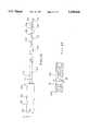
- FIG. 1is a top view of a tool embodying the invention.
- FIG. 2is an enlarged fragmentary central cross sectional view substantially taken on the line 2--2 of FIG. 1 and showing schematically the cooperating parts of a corresponding handpiece.
- FIG. 2Ais an enlarged sectional view taken substantially on the line 2A--2A of FIG. 2.
- FIG. 3is an enlarged fragment of FIG. 2 with the rotatable inner member shown in central cross section.
- FIG. 3Ais a fragmentary pictorial view of the angled distal tip portion of the FIGS. 1-3 tool.
- FIG. 4is an enlarged plan view of a preferred rotatable inner member head of the tool of FIGS. 1-3.
- FIG. 5is a central cross sectional view substantially taken on the line 5--5 of FIG. 4.
- FIG. 6is a distal end view of the FIG. 4 head.
- FIG. 7is a fragment of FIG. 5 showing a preferred tooth form.
- FIG. 8is a sectional view substantially taken on the line 8--8 of FIG. 3.
- FIG. 9is a sectional view substantially taken on the line 9--9 of FIG. 3.
- FIG. 10is an enlarged sectional view substantially taken on the line 10--10 of FIG. 3.
- FIG. 11is an enlarged sectional view substantially taken on the line 11--11 of FIG. 3.
- FIG. 12is a pictorial view of the rotatable drive hub of the FIG. 1 tool.
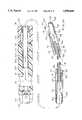
- FIG. 13is a side view in partial section of a further embodiment of the tool embodying the invention.
- FIG. 14is an enlarged sectional view substantially taken on the line 14--14 of FIG. 13.
- FIG. 15is an enlarged sectional view substantially taken on the line 15--15 of FIG. 13.
- FIG. 16is an enlarged fragmentary view of FIG. 13 with the rotatable inner member shown in central cross section.
- FIG. 17is an enlarged fragmentary bottom view of FIG. 13 with the rotatable inner member shown in partial cross section.
- FIG. 18is an enlarged plan view of the further embodiment of the rotatable inner member head of the tool of FIG. 13.
- FIG. 19is a central cross sectional view substantially taken on the line 19--19 of FIG. 18.
- FIG. 20is a bottom view of the head illustrated in FIGS. 18 and 19.
- FIG. 21is a proximal end view of the head illustrated in FIGS. 18-20.
- FIG. 22is a broken front elevational view of the rotatable drive hub and inner member of the embodiment illustrated in FIG. 13.
- FIG. 23is a central cross sectional view substantially taken on the line 23--23 of FIG. 22.
- FIG. 24is an enlarged fragmentary central cross sectional view of the tool of FIGS. 13-22 and showing schematically the flow paths of the tool.
- a tool 10(FIGS. 1 and 2) embodying the invention is adapted for chucking in a powered rotating surgical handpiece of any desired kind, an example which is disclosed in above-mentioned Cezana et al U.S. Pat. No. 5,192,292, (assigned to the assignee of the present invention).
- a handpieceis schematically indicated at HP in FIG. 2.
- the handpiece HPhas a housing H fixedly containing a suitable rotary drive motor means, indicated in broken lines at MM (for example electrically or fluid powered).
- the motor means MMhas a rotary output shaft SH extending forward therefrom and fixedly carrying at its front end a diametrically protruding drive pin DP (FIG. 2).
- the handpiece HPmay contain a suitable power source, such as electric batteries, in the example shown, same is connectible to a suitable remote power source P, for example electrical power source or a pressure gas source.
- a suitable remote power source Pfor example electrical power source or a pressure gas source.
- the handpiece HPalso preferably includes a connection to a suitable suction source S.
- the tool 10comprises a tubular outer member 11 (FIG. 2) comprising a proximal hollow base 12.
- An elongate tubular sleeve 13is fixedly telescoped in and extends coaxially forwardly from the hollow base 12.
- the sleeve 13includes a distal tip portion 14 and an intermediate portion 15 extending from the base 12 toward the distal tip portion 14.
- the sleeve 13is here a rigid, thin walled, constant diameter, circular cross-section tube of stainless steel or equivalent material.
- the base 12is configured to be rearwardly insertable in, fixedly held by, and releasably removable forward from a chuck C on the forward end of the handpiece HP. To cooperate with the chuck of the handpiece shown in above-mentioned U.S.
- the base 12(FIGS. 1 and 2) includes on its surface an annular groove 20 forward of a rearwardly opening, generally funnel shaped slot 21.
- the base slot 21receives a radially inward extending fixed pin in the chuck C, which fixes the outer member 11 against rotation in the handpiece HP.
- the annular groove 20 in the outer member base 21receives diametrically opposed half rings 23 in the chuck. The half rings are diametrically biased toward each other by spring means 24 in the chuck C, as schematically indicated in FIG.
- the handpiece HPincludes means, not shown, manually actuable to pull apart the half rings 23 to thereby allow tool 10 to be pulled forwardly out of the handpiece chuck C after surgery, or during surgery when it is desired to substitute a different tool into driving relationship with the handpiece HP.
- a driven rotatable elongate inner member 30extends coaxially and rotatably within the tubular outer member 11 (FIGS. 1 and 2).
- the rotatable inner member 30has a proximal end portion, defining a hub 31 rotatably drivably engageable by the rotary handpiece shaft SH and its transverse drive pin DP.
- the hub 31includes at least two (here four) diametrically opposed, evenly circumferentially distributed, rearward opening notches 32 circumferentially spaced by a corresponding number of rear extending fingers 33.
- the notches 32 and fingers 33surround and extend rearward from a central, blind, rear opening recess 34 (FIG. 2) in the hub 31.
- a coil compression spring 35(FIG. 2) is snugly housed in the recess 34 and extends rearward therefrom.
- the rotatable inner member 30has an intermediate portion 36 (FIG. 2) coaxially fixed to and extending forward from the hub 31.
- the rotatable intermediate portion 36is supported for rotation within the intermediate portion 15 of the tubular outer member 11 in a manner hereafter discussed.
- the rotatable inner member 30has a distal tip portion 40 fixed forward of the intermediate portion 36 for rotation therewith and snugly rotatably disposed within the distal tip portion 14 of the tubular outer member 11.
- the distal tip portions 14 and 40here have means, hereafter discussed more fully, for surgically working the tissue of a patient at a surgical site on the patient.
- Tools of the herein described typecan be provided with a variety of different purpose surgical tissue working means including burrs, cutters, etc. of conventional type.
- the distal tip portion 14 of the outer tubular member 11is provided with an angled, laterally and somewhat forwardly opening, planar window 41.
- the window 41has laterally opposed cutting edges.
- the window 41may be so formed by forming the distal tip portion of the tubular outer member with a semi-spherical closed end and then machining away a part thereof in an angled planar manner as here shown in FIGS. 1 and 2.
- the inner distal tip 40is rotatable snugly within the outer distal tip portion 14 and has a cutting edge 42 rotatable in shearing relation past the cutting edge of the window 41.
- the inner member 30is axially insertable forwardly into the tubular outer member 11 and is axially rearwardly removable therefrom when not installed on a handpiece HP.
- the forward end of the shaft SH of the handpiecepartly compresses the spring 35 (FIG. 2) of the inner member hub 31, to push the inner distal tip portion 40 forward snugly against the front end 43 of the distal tip portion 14 of the outer member 11, so as to axially accurately position the rotatable inner tip portion 40 with respect to the outer tip portion 14.
- the diametrical drive pin DP of the handpiece shaftenters and rides in a diametrically opposed pair of the notches 32 of the hub 31 and, upon rotation of the shaft SH, the drive pin DP correspondingly rotates the inner rotatable member 30 and thereby rotates the distal tip portion 40 thereof to rotationally move its cutting edge 42 past the corresponding cutting edges of the outer member window 41.
- the tool 10can be used for simultaneously cutting tissue at the surgical site and removing flowable material from the surgical site.
- the tool 10is conventional and one example thereof is shown in above-referenced Cezana et al U.S. Pat. No. 5,192,292.
- the intermediate portion 36 of the rotatable inner member 30comprises a rigid, solid (not hollow) shaft 44 having coaxial front, mid and rear parts 45F, 45M, and 45R of elongate cylindrical form and of diameter sufficiently less than the inside diameter of the sleeve 13 as to create an annular suction passage 46 between the shaft 44 and inside of the sleeve 13 for drawing of flowable materials from a surgical site.
- the suction passage 46runs the length of the tool from the distal tip portion 14 of the tubular outer member 11 rearward through the base 12 into the front end of the hub 31 and radially outward therefrom (as hereafter detailed) and through a portion of the handpiece HP indicated by the arrows 46A to the conventional suction source S.
- the outside diameter of the shaft parts 45F, 45M, and 45Ris about 2/3 the inside diameter of the sleeve 13, leaving a substantial radial clearance therebetween for suction of fluid materials from the surgical site.
- axially elongate front and rear bushings 50F and 50Rrespectively are disposed rotatably on reduced diameter parts 51 and 52 of the shaft 44 between the axially spaced shaft parts 45R, 45M and 45R.
- the shaft parts 51 and 52are elongate and cylindrical but of diameter less than the shaft parts 45F, 45M and 45R.
- each bushing 50F, Rhas a slot 53 running axially the length thereof and opening radially outward to the interior of the sleeve 13 and inward to a coaxial, circular cross section bore 54 which extends the length thereof and rotatably coaxially supports the corresponding reduced diameter portion 51 or 52 of the shaft 44.
- the narrowest width of the slot 53is slightly more than the outside diameter of the corresponding reduced diameter shaft part 51, 52, permitting the bushing to flex circumferentially enough to widen the slot 53 and allow radial snapping of the bushing over the shaft into the coaxially centered relation shown in FIG. 2A.
- the bushings 50F, Rhave circumferentially distributed channels 55 indenting the perimeter thereof for the length thereof, one of the channels 55 constituting a funnel-like circumferential widening of the slot 53.
- the channels 55continue the suction flow passage 46 axially along and past the bushings 50F, R.
- the bushings 50F, Reach have three circumferentially distributed channels 55, leaving therebetween three evenly circumferentially spaced, radially outwardly extending lobes 56 (FIG. 2A) radially sized and circumferentially shaped to slide, with the shaft, axially forwardly into the sleeve 13 to the location shown in FIG. 2, for rotatably supporting the shaft with respect hereto.
- the bushings 50F, Rare substantially coextensive in length with the corresponding reduced diameter shaft parts 51, 52.
- the bushings 50F, Rare thus axially snugly sandwiched between the shaft front, mid and rear parts 45F, M, R.
- the bushings 50F, Rare preferably of low friction molded plastics material, such as polycarbonate (in one unit partially glass fiber (30%) filled polycarbonate).
- the shaft 44further includes a drive end portion 57 (FIG. 2) which extends coaxially and integrally fixedly rearwardly from the rear shaft part 45R and rearward coaxially beyond the rear end of the hollow base 12 and is coaxially fixed in driven relation in the hub 31.
- the base 12 and hub 31are preferably of rigid molded plastics material, such as polycarbonate.
- the base 12 and hub 31are conventionally fixed coaxially as by molding on the rear end portions of the sleeve 13 and shaft 44 respectively.
- the sleeve 13 and shaft 44are preferably of rigid stainless steel.
- the hub 31(FIG. 12) is formed to receive flowable material from the surgical site, and more immediately from the central bore 60 (FIG. 2), and to pass it to the surrounding portion of the handpiece HP for transfer through the suction passage (not shown) in the handpiece to the suction source S.
- the front end of the hub 31defines a ring 61 having a central opening 62 for loosely coaxially receiving therethrough the shaft driven end portion 57 (FIG. 2).
- the main body 63 (FIG. 12) of the hub 31is axially spaced from the ring 61 by circumferentially spaced columns 64 defining open windows 65 circumferentially therebetween.
- the windows 65open radially outward and also open rearward into corresponding rearwardly extending, correspondingly circumferentially spaced, troughs 66, which end blindly at 67, in spaced relation ahead of the notches 32.
- suctioned flowable material from the surgical sitepasses rearwardly from the central bore 60 of the base 12 (FIG. 2), along the shaft driven end portion 57, through the central opening 62 and more particularly through the annular space between the ring 61 and shaft driven end portion 57, into the flow direction changing space bounded by the columns 64.
- the shaft rearward driven end portion 57continues rearward into the main body 63 of the hub 31 (FIG. 2) and abuts a step 68 (FIG. 8) which faces forward from a location adjacent the rear opening recess 34 so that forward pressure on the hub 31 exerts a similar forward pressure against the shaft 44.
- FIG. 2Attention is directed to FIG. 2.
- the distal tip portion 14 (FIG. 2) of the tubular outer member 11is angled, here at about 15°, with respect to the intermediate portion 15 of the sleeve 13, by reason of an angled portion 70 of the sleeve.
- the angled portion 70is smoothly curved as seen in FIG. 2 and the interior of the sleeve maintains its normal circular cross section and diameter from the intermediate portion 15, through the angled portion 70, and into the distal end portion 14.
- the smooth curvature of the angled portion 70is achieved by drawing its central length axis arc on a relatively long radius, for example 6 to 8 times the outside diameter of the sleeve 13.
- the distal tip portion 40 (FIGS. 2 and 3) of the inner rotatable member 30comprises a tissue working head 71.
- the head 71has a substantially modified bullet shape and indeed can be conveniently manufactured from a bullet shaped blank.
- the head 71has a convexly rounded nose 72 which snugly rotates within and bears axially forward on the inner face of the convexly rounded front end 43 of the distal tip portion 14 of the tubular outer member 11.
- the nose 72 and front end 43are both preferably hemispherical, as shown.
- a central bore 73is a conveniently drilled coaxially in the rear end 74 of the head 71 and extends coaxially forward to the nose 72 (FIG. 3).
- the central bore 73extends forward from the head rear end 74. Approximately 3/5 of the length of the head 71 is radially relieved to provide a reduced outside diameter and wall thickness, cylindrical, substantially tubular tail 75.
- the tail 75has about the same outer diameter as the shaft portion 45F and is thus radially surrounded by an annular front extension 46FE of the suction passage 46.
- the head 71is thus left with a forward radial bearing portion 76, ahead of the front end of the tail 75, namely ahead of the forward extension 46FE of the suction passage and behind the window 41 in the tubular outer member 11. This bearing portion 76 coaxially rotatably supports the head 71 within the distal tip portion 14 of the tubular outer member 11.
- a circumferential portion(the upper circumferential portion with the head oriented rotatably as shown in FIG. 3) is removed in any convenient way, for example by milling with a relatively small diameter milling cutter of circular cylindrical shape generally indicated in dotted lines at M in FIG. 7.
- a relatively small diameter milling cutterof circular cylindrical shape generally indicated in dotted lines at M in FIG. 7.
- the mouthis thus defined by a series of upwardly concave, transversely extending, semi-circular cross section grooves 81 arranged side by side along a substantially chordal plane from the rearward end to the forward end of the mouth 80 and defining the transversely opposed pair of cutting edges 42 on transversely opposite sides of the mouth 80 which in profile, as seen in FIG. 5, provide an appearance of a series of teeth 82.
- the mouth 80 here shownis structured to effectively cooperate its cutting edges 42 in an efficient shearing manner with the adjacent edges of the window 41 of the tubular outer member 11, it will be understood that other types of tissue working cooperation, and structure therefore, may be provided in place of the particular window 41 and mouth 80 here shown.
- the head 71provides a path for fluent material, including bits of tissue and the like, to be drawn from the surgical site outside the distal portion 14 of the outer tubular member 11 and into the central bore 73 of the head 71, as generally indicated by the further arrows 46E entering the central bore 73 through the window 41 and mouth 80 in FIG. 3, from the surgical site.
- fluent materialincluding bits of tissue and the like
- a transverse, chordal (here substantially diametral) flow port 83(FIG. 3) is formed (preferably milled) in the forward end of the tubular tail 75.
- the port 83is here about the same axial length as the nose portion of the head extending forward therefrom, and about twice the axial length of the residual portion of the tail 75 extending rearward therefrom.
- the flow port 83provides large area communication with the central bore 73.
- the port 83allows relatively free flow of flowable materials therethrough from the mouth 80 rearwardly and radially outwardly into the annular flow passage 46 which extends rearward within the tubular outer member 11 as above described.
- the rotatable elongate inner member 30further includes a coaxial flexibly bendable portion 90 (FIG. 3) coaxially fixed at its opposite ends to the front end of the shaft front part 45F and to the rear end 74 of the head 71 for rotatably driving the head 71 from the shaft 44 and allowing the shaft 44 to axially press the nose 72 of the head 71 forwardly against the rounded front end 43 of the tubular outer member 11. This keeps the mouth 80 in axially correct position with the window 41 while yet allowing bending of the rotatable inner member 30, in the manner seen at FIG.
- a coaxial flexibly bendable portion 90(FIG. 3) coaxially fixed at its opposite ends to the front end of the shaft front part 45F and to the rear end 74 of the head 71 for rotatably driving the head 71 from the shaft 44 and allowing the shaft 44 to axially press the nose 72 of the head 71 forwardly against the rounded front end 43 of the tubular outer member 11.
- the flexible bendable portion 90is to be maintained, during rotation, coaxial with the generally curved surrounding angled portion 70 of the outer tubular member and hence so as to maintain a constant thickness annular space therebetween during rotation, as generally indicated in FIG. 2.
- the member 90while flexibly bendable during rotation is non-twistable so as to transmit the necessary rotational driving torque from the handpiece HP to the head 71.
- the flexibly bendable portion 90(FIG. 2) comprises an elongate flexible member 91 having a central part 92 located within the angled portion 70 of the tubular outer member 11 and wherein bending during rotation occurs to accommodate the angle of such angled portion 70.
- the flexible member 91further includes elongate distal and proximal parts coaxially flanking the central part 92 and respectively extending coaxially into fixed coaxial driving engagement with the adjacent rear and front ends of the head 71 and shaft 44.
- the flexible member 91comprises length of conventional wound-wire flexible shafting.
- the flexible member 91was a 0.070 inch diameter, 1.65 inch long piece of flexible shafting constructed of stainless steel wire, and available from Suhner Manufacturing Inc. of Rome, Ga. under part No. A-225-4784. That particular unit is shown in FIG. 3 wherein the flexible member 91 comprises a coaxial center wire 95, wound with a first layer of intermediate wound wires 96 (here four in number) in one circumferential direction, which first circumferential layer is then over wound with a second layer of outer wound wires 97 (here five in number). To prevent unwinding of the wires, the ends of the flexible member 91 are here fused by welding as generally indicated at 100. The intermediate and outer wires are tightly wound in a conventional manner.
- the end portions of the distal and proximal parts 93 and 94 of the flexible member 91are coaxially connected to the head 71 and shaft 44 preferably by snug coaxial reception in the rear end portion of the central bore 73 of the head 71 and in a forward facing cylindrical recess 101 (FIG. 3) in the front end of the shaft 44.
- Actual fixing of the thus inserted ends of the flexible member 91can be in any conventional manner. It is convenient to crimp the surrounding front end portion of the shaft 44 tightly to the proximal end portion 94 of the flexible member 91 as indicated at 102 in FIG. 3. The same can be done with respect to the distal end portion 93 housed in the head 71 although adhesive bonding, welding or the like may be used instead.
- the entire portion of the flexible member 91 between the shaft 44 and head 71is preferably snugly covered by a relatively thin-walled sheath 103 (FIG. 3).
- the sheath 103prevents particles in the suctioned flowable material from entering between the coils of the outer wire layer 96 as the flexible member 91 flexes during rotation.
- a solid particle entering between adjacent wire coils on the outside of the bendcannot interfere with contact between such coils on the inside of the bend, following 180° of shaft rotation.
- the sheath 103can act as a buffer preventing direct contact between the outer wires 96 of the flexible member 91 and the inside wall of the angled portion 70 of the tubular outer member 11, in the highly unlikely event of a malfunction wherein the flexible member 91 displaces radially sufficient to brush against the inside surface of the outer tubular member.
- the sheath 103is conveniently a length of conventional heat shrink tubing, preferably polyester heat shrink tubing.
- This materialis relatively low friction material and is capable of shrinking almost half diameter upon application of modest heat thereto, so as to snugly grip the outside of the flexible member 91.
- the sheath covered flexible member 91has an effective outside diameter no more than that of the shaft 44 and tail 75 of the head 71, so as to continue the annular passage 46 axially therepast and not impede rearward flow of flowable material from the surgical site therepast.
- the flexible member 91(FIG. 2) will maintain its coaxial location within the angled portion 70 of the outer tubular member and hence maintain equal radial spacing therein during rotation in surgical use at substantial rotational speeds, for example as high as about 3,000 to 6,000 rpm, given that the head 71 is held forwardly against the front end 43 of the outer tubular member and with substantial axial extension of distal and proximal parts 93 and 94 of the flexible member axially beyond the angled portion 70 of the outer tubular member.
- FIG. 2In one unit constructed according to the invention, and as shown in FIG.
- the distal and proximal parts 93 and 94 of the flexible memberoccupy the straight parts of the outer tubular member flanking the angled portion 70 and are each at least as long as the central part 92 of the flexible member.
- the central part 92occupies the angled portion 70 of the outer tubular member and hence is the part called upon to flex during rotation.
- the flanking distal and proximal parts 93 and 94need not flex and are at least as long as the flexing central part 92 which they flank.
- the tool 10is readily manufacturable as follows, for example. Following formation of hemispherical distal tip portion 14 and angled portion 70 of the outer tubular member 11, the base 12 is formed and fixed thereto. As to the rotatable inner member, the shaft 44 and head 71 are formed as shown and the hub 31 is formed and fixed on the rear end portion of the shaft 44. The coil compression spring 35 may at any time be inserted into the rear facing recess 34 in the rear end of the base 12. The outer wrapped wire layer 93 of the flexible central portion 92 of the flexible member 91 is loosely sleeved over with the tubular heat shrinkable sheath 103 and its ends are fixedly telescoped in the proposed ends of the shaft 44 and head 71.
- the molded plastic bushings 50R and 50Fare radially resiliently snapped onto the reduced diameter shaft portions 51 and 52 respectively so as to rotate freely and coaxially thereon.
- the tool 10can be assembled by insertion of the rotatable inner member 30, head 71 first, forwardly into the rear end of the tubular outer member 11.
- This telescoping insertionproceeds most easily with the window 41 and mouth 80 facing in the same circumferential direction, for example both facing up with the tool 10 horizontal.
- the chamfered forward ends of the bushings 50F, Rslide axially therewith, in a low friction manner, forward into their positions shown in the tubular outer member 11 and the head 71 comes axially to press against the closed front end 43 of the outer tubular member 11.
- the flexible member 91accommodates the curvature of the angled portion 70 of the outer tubular member since, while it is laterally bendable it is not axially compressible.
- the tool 10is rearwardly inserted into the chuck C of a handpiece HP in a conventional way, namely by telescoped insertion rearwardly thereinto of the drive hub 31 and outer member base 12.
- the split ring 23 and pin 22 of the chuck Caxially and radially fix the outer tubular member 11 with respect to the handpiece HP
- the handpiece shaft SH and double pin DPrespectively resiliently push forward the resilient inner member distal tip portion 40 against the closed front end 43 of the outer tubular member and insert into opposed notches 32 of the hub 31 to rotatably drive the rotatable inner member upon conventional actuation of the motor means of the handpiece.
- the handpieceis connected to a suitable power source P (e.g. electric power source) for electric motor MM, and normally to a suitable suction source S.
- a suitable power source Pe.g. electric power source
- MMelectric motor
- Ssuction source
- the surgeoncan then insert the distal tip portion 14 of the tool in a small, for example arthroscopic, incision into a surgical site in a patient, for example for arthroscopic trimming of the edge of the meniscus cartilage in a knee joint.
- the angling of the distal tip portion 14 with respect to the proximal portion of the tool 10permits the surgeon to reach, and orient the cutting window 41 toward, portions of the surgical site which would not readily be accessible by a straight tool without applying excessive tilting or sideways forces to the tissue of the patient through which the tip of the tool is inserted, or without relocating the tool in a new incision.
- the flexibly bendable portion 90(FIG. 2) flexes as needed to maintain coaxiality with the angled portion 70 of the outer tubular member 11, i.e. to maintain its centered position therein shown in FIG. 2, during rotation of the inner member.
- the flexibly bendable portion 90cannot straighten because of the axial compression force on the inner tubular member due to its axial entrapment between (1) the spring 35 and the drive shaft SH of the handpiece HP at the proximal end thereof and (2) the rounded, closed front end 43 of the outer tubular member at the distal end thereof.
- Rotation of the head 71moves the cutting edges 42 of the inner member in a circumferential shearing manner with respect to the cutting edges defined by the window 41, so as to separate small bits of tissue sequentially from the intended portion of the surgical site.
- the surgical siteis infused with irrigation liquid, from a suitable conventional source not shown.
- irrigation liquidfrom a suitable conventional source not shown.
- excess irrigation liquidwith bits of tissue and other particulate matter entrained therein, is drawn from the surgical site through the window 41 and repetitively as the head 71 rotates, through the mouth 80 thereof, through the central bore 73 thereof and radially out the port 83 thereof and rearwardly along the annular suction passage 46 surrounding the rotating inner member 30.
- Such rearward flowis facilitated by the channels 55 between the lobes 56 of the bushings 50F, R and by the radial spacing of the rotatable inner member 30 from the interior wall of the tubular outer member 11.
- the tool 10is constructed in a relatively inexpensive manner so as to be disposable after a single use (for example after a single surgical procedure), so as to avoid need for subsequent sterilization, the costs thereof, the risk of imperfect sterilization, and the resulting risk of contamination of a second patient by bodily materials of a first.
- FIGS. 13-24show a further embodiment of the invention, which is substantially the same as that described above with respect to FIGS. 1-12 except as discussed below.
- Features of the FIGS. 1-24 embodiment similar to those of FIGS. 1-12,are identified by the same reference numerals with the suffix A added.
- the driven rotatable elongate inner member 30Aextends coaxially and rotatably within the tubular outer member 11A, but is modified to further facilitate the removal of tissue along the length thereof.
- the flow path of removed tissueis modified as shown by the reference arrows in FIG. 24, to minimize restriction of flow.
- the rotatable inner member 30A(FIG. 23) has a drive end portion 57A which is conventionally coaxially fixed in driven relation within an inner bore 110 of the hub 31A.
- the inner bore 110extends rearwardly from the inner member 30A and opens into a transverse access bore 112 which communicates with the suction source S (not illustrated in FIGS. 23 and 24) to remove tissue from the inner member 30A.
- the inner member 30Aincludes a proximal portion 114 coaxially fixed to and extending forward from the hub 31A.
- the outside diameter of the portion 114preferably, is only slightly smaller than the inside diameter of the sleeve 13A.
- the proximal portion 114is supported for rotation within the hollow base 12A and the sleeve 13A of the tubular outer portion 11A by bearing sleeves 116 which are disposed about the outer peripheral surface of the inner member 30A.
- bearing sleeves 116are thin walled (e.g. approximately 0.001 in.
- a proximal bearing sleeve 116Pwhich is disposed within the hollow base 12A during use and a distal bearing sleeve 116D which is disposed within the sleeve 13A away from the base 12A.
- the distal bearing sleeve 116Dfurther serves the purpose of preventing undesirable entry of tissue between the inner member 30A and the sleeve 13A, as generally seen in FIG. 24.
- the proximal portion 114is provided with a tubular shape which defines an interior suction passage 46I through the interior and along the axial length thereof from a distal end and extending to a proximal end at the hub 31A.
- This interior suction passage 46Icoaxially communicates with the inner bore 110 of the hub 31A.
- the inner member 30Aalso includes a distal portion 118 which connects to a transition portion 120 of the proximal portion 114.
- the distal portion 118is similar to that previously described herein at 40, in that it includes a coaxial flexibly bendable portion 90A which has a radial clearance between the outside diameter thereof and an inside diameter of the sleeve 13A, as can be seen in FIG. 24. This radial clearance defines an annular suction passage 46A.
- the transition portion 120is formed integral with the proximal portion 114 and extends forwardly therefrom.
- the transition portion 120necks down from the increased diameter at the proximal portion 114 and reduces to a reduced diameter portion 122 which has an outside diameter proximate the outside diameter of the distal portion 118.
- the transition portion 120includes a lateral opening 124 which communicates with the interior of the proximal portion 114 and accordingly, communicates with the interior suction passage 46I thereof.
- This opening 124also communicates with the annular suction passage 46A adjacent thereto.
- the lateral opening 124is elongate so as to provide a sufficiently sized opening to permit free access of tissue therein.
- the opening 124extends from the reduced diameter portion 122 and terminates proximate the maximum diameter of the proximal portion 114.
- the transition portion 120terminates forwardly at an entry opening 126 which is adapted to coaxially receive the proximal end 94A of the bendable portion 90A in tight-fitting engagement.
- the bendable portion 90Amay be permanently affixed by such conventional techniques as welding or brazing or staking.
- the distal portion 118Forwardly of the transition portion 120 the distal portion 118, and more particularly, the bendable portion 90A thereof is formed substantially identical to that of the previous embodiment described herein.
- the distal portion 118has a reduced diameter in comparison to the inner diameter of the outer member 11A, such that the annular suction passage 46A is formed between the outer surface 136 of the distal portion 118 and the inner surface 138 of the sleeve 13A of the outer member 11A.
- the tissueWith the lateral opening 124 provided in the transition portion 120, the tissue flows along the annular suction passage 46A and into the interior suction passage 46I of the proximal portion 114.
- the bendable portion 90Ahas a distal end 93A which terminates proximate the distal tip portion 14A of the outer member 11A and is coaxially secured to the rear end 74A of the tissue working head 71A.
- the head 71Aincludes a central bore 73A, a reduced diameter tubular tail 75A, cutting edges 42A and a transverse, chordal flow port 83A.
- the head 71Aalso includes means for working tissue having an upward opening mouth 80A.
- a path for fluent materialis provided through the head 71A from the mouth 80A through the central bore 73A and out through the flow port 83A.
- the flow port 83Ais modified so as to taper forwardly and terminate at a distal edge 140 thereof which increases the size of the port 83A.
- This distal edge 140is disposed substantially diametrically opposite a proximal edge 142 of the tissue working cutting edges 42A.
- a substantially diagonal flow pathresults between the cutting edges 42A and the flow port 83A which provides an improved flow of the tissue being removed. This improved flow avoids unnecessary contact with the walls of the head 71A which can impede flow.
- This arrangementprovides an increased opening size for the flow port 83A which further facilitates flow of fluent material therefrom.
- the radial bearing portion 76A of the head 71Ais provided with a thinner wall thickness and the interior surface of the central bore 73A is shaped so as to taper rearwardly to the reduced diameter tail 75A thereof.
- This tapering arrangementprovides the proximal edge 142 with a reduced cross-sectional area and provides a sloping surface in the central bore 73A which further facilitates flow therethrough. In other words, this maximizes the size of the central bore 73A in the region of the distal edge 140 and the proximal edge 142.
- This tapering of the interior surface of the head 71Apreferably is accomplished by forming the head 71A with a tubular shape having a uniform diameter. Then, the distal end 74A is swaged to form the reduced diameter tail portion 75A.
- tail portion 75Awith a C-shaped cross section which is accomplished by cutting off a bottom section of the tail 75A which thereby provides an opening which communicates with the annular suction passage 46A as illustrated in FIG. 24.
- the tail portion 75Areceives and is coaxially fixedly secured to the distal end 93A of the bendable portion 90A.
- the distal end of the bendable portion 90Ais sufficiently secured by providing the tail 75A with this C-shaped arcuate section of sufficient size so that the bendable portion 90A may not be dislodged through the opening of the tail 75A.
- the bendable portion 90Ais further secured therein by such securing techniques as welding or brazing.
- the inner member 30A of this embodimentis operated substantially as described herein with respect to the aforesaid embodiment.
- Flowis improved from the head 71A to the hub 3A by the arrangement described herein.
- tissueflows through the central bore 73A, out of the flow port 83A, along the annular suction passage 46A disposed about the bendable portion 90A until reaching the transition portion 120.
- the tissuewill flow through the lateral opening 124 and thereafter through the interior suction passage 46A of the proximal portion 114.
Landscapes
- Health & Medical Sciences (AREA)
- Surgery (AREA)
- Life Sciences & Earth Sciences (AREA)
- Biomedical Technology (AREA)
- Nuclear Medicine, Radiotherapy & Molecular Imaging (AREA)
- Engineering & Computer Science (AREA)
- Orthopedic Medicine & Surgery (AREA)
- Heart & Thoracic Surgery (AREA)
- Medical Informatics (AREA)
- Molecular Biology (AREA)
- Animal Behavior & Ethology (AREA)
- General Health & Medical Sciences (AREA)
- Public Health (AREA)
- Veterinary Medicine (AREA)
- Surgical Instruments (AREA)
Abstract
Description
Claims (24)
Priority Applications (1)
| Application Number | Priority Date | Filing Date | Title |
|---|---|---|---|
| US08/626,688US5690660A (en) | 1993-10-27 | 1996-04-02 | Arthroscopic cutter having curved rotatable drive |
Applications Claiming Priority (4)
| Application Number | Priority Date | Filing Date | Title |
|---|---|---|---|
| US14419593A | 1993-10-27 | 1993-10-27 | |
| US08/313,407US5437630A (en) | 1993-10-27 | 1994-09-27 | Arthroscopic cutter having curved rotatable drive |
| US43369595A | 1995-05-03 | 1995-05-03 | |
| US08/626,688US5690660A (en) | 1993-10-27 | 1996-04-02 | Arthroscopic cutter having curved rotatable drive |
Related Parent Applications (1)
| Application Number | Title | Priority Date | Filing Date |
|---|---|---|---|
| US43369595AContinuation | 1993-10-27 | 1995-05-03 |
Publications (1)
| Publication Number | Publication Date |
|---|---|
| US5690660Atrue US5690660A (en) | 1997-11-25 |
Family
ID=27386051
Family Applications (1)
| Application Number | Title | Priority Date | Filing Date |
|---|---|---|---|
| US08/626,688Expired - LifetimeUS5690660A (en) | 1993-10-27 | 1996-04-02 | Arthroscopic cutter having curved rotatable drive |
Country Status (1)
| Country | Link |
|---|---|
| US (1) | US5690660A (en) |
Cited By (98)
| Publication number | Priority date | Publication date | Assignee | Title |
|---|---|---|---|---|
| US5913867A (en)* | 1996-12-23 | 1999-06-22 | Smith & Nephew, Inc. | Surgical instrument |
| US5922003A (en)* | 1997-05-09 | 1999-07-13 | Xomed Surgical Products, Inc. | Angled rotary tissue cutting instrument and method of fabricating the same |
| US6068642A (en)* | 1996-03-01 | 2000-05-30 | Orthopaedic Innovations, Inc. | Flexible cutting tool and methods for its use |
| US6086544A (en)* | 1999-03-31 | 2000-07-11 | Ethicon Endo-Surgery, Inc. | Control apparatus for an automated surgical biopsy device |
| US6120462A (en)* | 1999-03-31 | 2000-09-19 | Ethicon Endo-Surgery, Inc. | Control method for an automated surgical biopsy device |
| US6273862B1 (en) | 1998-10-23 | 2001-08-14 | Ethicon Endo-Surgery, Inc | Surgical device for the collection of soft tissue |
| US6585664B2 (en) | 2000-08-02 | 2003-07-01 | Ethicon Endo-Surgery, Inc. | Calibration method for an automated surgical biopsy device |
| US6620180B1 (en) | 1998-09-09 | 2003-09-16 | Medtronic Xomed, Inc. | Powered laryngeal cutting blade |
| US20030191488A1 (en)* | 2002-04-09 | 2003-10-09 | Braden Robison | Surgical instrument |
| US20040034280A1 (en)* | 1998-10-23 | 2004-02-19 | Salvatore Privitera | Surgical device for the collection of soft tissue |
| US20040054299A1 (en)* | 2001-07-20 | 2004-03-18 | Burdorff Mark A. | Calibration method for an automated surgical biopsy device |
| US20040087958A1 (en)* | 2002-10-30 | 2004-05-06 | Myers Reese K. | Curved surgical tool driver |
| US20040143164A1 (en)* | 2003-01-17 | 2004-07-22 | Loubert Suddaby | Laminectomy suction and retraction device |
| US20040181250A1 (en)* | 2003-02-20 | 2004-09-16 | Adams Kenneth M | Surgical elongate blade assembly with interchangeable inner member, kit and method relating thereto |
| US20040181185A1 (en)* | 2003-03-14 | 2004-09-16 | Yi-Chang Lee | Device for removing diseased surface tissues |
| US20050090848A1 (en)* | 2003-10-22 | 2005-04-28 | Adams Kenneth M. | Angled tissue cutting instruments and method of fabricating angled tissue cutting instruments having flexible inner tubular members of tube and sleeve construction |
| US20050159767A1 (en)* | 2004-01-21 | 2005-07-21 | Adams Kenneth M. | Angled tissue cutting instrument having variably positionable cutting window, indexing tool for use therewith and method of variably positioning a cutting window of an angled tissue cutting instrument |
| US20060200180A1 (en)* | 2003-03-14 | 2006-09-07 | Yi-Chang Lee | Device for removing diseased surface tissues |
| US20060264927A1 (en)* | 2005-03-04 | 2006-11-23 | Gyrus Ent, L.L.C. | Surgical instrument and method |
| US20070219539A1 (en)* | 2006-03-15 | 2007-09-20 | Andreas Efinger | Flexible Hollow Shaft For A Medical Instrument |
| EP1878389A1 (en)* | 2006-07-04 | 2008-01-16 | Helmut- Schmidt- Universität Universität der Bundeswehr Hamburg | Device for positioning a tool |
| US20080114365A1 (en)* | 2006-10-30 | 2008-05-15 | Sasing Jude L | Surgical cutting devices and methods |
| US20080208233A1 (en)* | 2006-12-21 | 2008-08-28 | Aaron Barnes | Disposable vitrectomy handpiece |
| WO2008145380A1 (en)* | 2007-05-31 | 2008-12-04 | Gebr. Brasseler Gmbh & Co. Kg | Surgical instrument and method for production thereof |
| US20090088784A1 (en)* | 2007-09-27 | 2009-04-02 | Doheny Eye Institute | Selectable stroke cutter |
| WO2009140399A3 (en)* | 2008-05-16 | 2010-03-11 | Ethicon Endo-Sergery, Inc. | Endoscopic rotary access needle |
| US20100249700A1 (en)* | 2009-03-27 | 2010-09-30 | Ethicon Endo-Surgery, Inc. | Surgical instruments for in vivo assembly |
| US20110152867A1 (en)* | 2009-12-18 | 2011-06-23 | Joseph Petrzelka | Articulating Tool and Methods of Using |
| US8029504B2 (en) | 2007-02-15 | 2011-10-04 | Ethicon Endo-Surgery, Inc. | Electroporation ablation apparatus, system, and method |
| US8037591B2 (en) | 2009-02-02 | 2011-10-18 | Ethicon Endo-Surgery, Inc. | Surgical scissors |
| US8070759B2 (en) | 2008-05-30 | 2011-12-06 | Ethicon Endo-Surgery, Inc. | Surgical fastening device |
| US8075572B2 (en) | 2007-04-26 | 2011-12-13 | Ethicon Endo-Surgery, Inc. | Surgical suturing apparatus |
| US8100922B2 (en) | 2007-04-27 | 2012-01-24 | Ethicon Endo-Surgery, Inc. | Curved needle suturing tool |
| US8114072B2 (en) | 2008-05-30 | 2012-02-14 | Ethicon Endo-Surgery, Inc. | Electrical ablation device |
| US8114119B2 (en) | 2008-09-09 | 2012-02-14 | Ethicon Endo-Surgery, Inc. | Surgical grasping device |
| US8142473B2 (en) | 2008-10-03 | 2012-03-27 | Tyco Healthcare Group Lp | Method of transferring rotational motion in an articulating surgical instrument |
| US8157834B2 (en) | 2008-11-25 | 2012-04-17 | Ethicon Endo-Surgery, Inc. | Rotational coupling device for surgical instrument with flexible actuators |
| US8172772B2 (en) | 2008-12-11 | 2012-05-08 | Ethicon Endo-Surgery, Inc. | Specimen retrieval device |
| US8211125B2 (en) | 2008-08-15 | 2012-07-03 | Ethicon Endo-Surgery, Inc. | Sterile appliance delivery device for endoscopic procedures |
| US8241204B2 (en) | 2008-08-29 | 2012-08-14 | Ethicon Endo-Surgery, Inc. | Articulating end cap |
| US8252057B2 (en) | 2009-01-30 | 2012-08-28 | Ethicon Endo-Surgery, Inc. | Surgical access device |
| US20120221033A1 (en)* | 2011-02-28 | 2012-08-30 | Jack Robert Auld | Surgical probe with increased fluid flow |
| US8262680B2 (en) | 2008-03-10 | 2012-09-11 | Ethicon Endo-Surgery, Inc. | Anastomotic device |
| US8262655B2 (en) | 2007-11-21 | 2012-09-11 | Ethicon Endo-Surgery, Inc. | Bipolar forceps |
| US8262563B2 (en) | 2008-07-14 | 2012-09-11 | Ethicon Endo-Surgery, Inc. | Endoscopic translumenal articulatable steerable overtube |
| US8317806B2 (en) | 2008-05-30 | 2012-11-27 | Ethicon Endo-Surgery, Inc. | Endoscopic suturing tension controlling and indication devices |
| US8337394B2 (en) | 2008-10-01 | 2012-12-25 | Ethicon Endo-Surgery, Inc. | Overtube with expandable tip |
| US8353487B2 (en) | 2009-12-17 | 2013-01-15 | Ethicon Endo-Surgery, Inc. | User interface support devices for endoscopic surgical instruments |
| US8361112B2 (en) | 2008-06-27 | 2013-01-29 | Ethicon Endo-Surgery, Inc. | Surgical suture arrangement |
| US8361066B2 (en) | 2009-01-12 | 2013-01-29 | Ethicon Endo-Surgery, Inc. | Electrical ablation devices |
| US8403926B2 (en) | 2008-06-05 | 2013-03-26 | Ethicon Endo-Surgery, Inc. | Manually articulating devices |
| US8409200B2 (en) | 2008-09-03 | 2013-04-02 | Ethicon Endo-Surgery, Inc. | Surgical grasping device |
| US8480689B2 (en) | 2008-09-02 | 2013-07-09 | Ethicon Endo-Surgery, Inc. | Suturing device |
| US8480657B2 (en) | 2007-10-31 | 2013-07-09 | Ethicon Endo-Surgery, Inc. | Detachable distal overtube section and methods for forming a sealable opening in the wall of an organ |
| US8496574B2 (en) | 2009-12-17 | 2013-07-30 | Ethicon Endo-Surgery, Inc. | Selectively positionable camera for surgical guide tube assembly |
| US8506564B2 (en) | 2009-12-18 | 2013-08-13 | Ethicon Endo-Surgery, Inc. | Surgical instrument comprising an electrode |
| US8529563B2 (en) | 2008-08-25 | 2013-09-10 | Ethicon Endo-Surgery, Inc. | Electrical ablation devices |
| US8568410B2 (en) | 2007-08-31 | 2013-10-29 | Ethicon Endo-Surgery, Inc. | Electrical ablation surgical instruments |
| US8579897B2 (en) | 2007-11-21 | 2013-11-12 | Ethicon Endo-Surgery, Inc. | Bipolar forceps |
| US8608652B2 (en) | 2009-11-05 | 2013-12-17 | Ethicon Endo-Surgery, Inc. | Vaginal entry surgical devices, kit, system, and method |
| US8652150B2 (en) | 2008-05-30 | 2014-02-18 | Ethicon Endo-Surgery, Inc. | Multifunction surgical device |
| US8679003B2 (en) | 2008-05-30 | 2014-03-25 | Ethicon Endo-Surgery, Inc. | Surgical device and endoscope including same |
| US8771260B2 (en) | 2008-05-30 | 2014-07-08 | Ethicon Endo-Surgery, Inc. | Actuating and articulating surgical device |
| US8828031B2 (en) | 2009-01-12 | 2014-09-09 | Ethicon Endo-Surgery, Inc. | Apparatus for forming an anastomosis |
| US8888792B2 (en) | 2008-07-14 | 2014-11-18 | Ethicon Endo-Surgery, Inc. | Tissue apposition clip application devices and methods |
| US8906035B2 (en) | 2008-06-04 | 2014-12-09 | Ethicon Endo-Surgery, Inc. | Endoscopic drop off bag |
| US8939897B2 (en) | 2007-10-31 | 2015-01-27 | Ethicon Endo-Surgery, Inc. | Methods for closing a gastrotomy |
| US8979768B2 (en) | 1998-10-23 | 2015-03-17 | Devicor Medical Products, Inc. | Surgical device for the collection of soft tissue |
| US8986199B2 (en) | 2012-02-17 | 2015-03-24 | Ethicon Endo-Surgery, Inc. | Apparatus and methods for cleaning the lens of an endoscope |
| US9005198B2 (en) | 2010-01-29 | 2015-04-14 | Ethicon Endo-Surgery, Inc. | Surgical instrument comprising an electrode |
| US9028483B2 (en) | 2009-12-18 | 2015-05-12 | Ethicon Endo-Surgery, Inc. | Surgical instrument comprising an electrode |
| US9049987B2 (en) | 2011-03-17 | 2015-06-09 | Ethicon Endo-Surgery, Inc. | Hand held surgical device for manipulating an internal magnet assembly within a patient |
| US9078662B2 (en) | 2012-07-03 | 2015-07-14 | Ethicon Endo-Surgery, Inc. | Endoscopic cap electrode and method for using the same |
| US9226772B2 (en) | 2009-01-30 | 2016-01-05 | Ethicon Endo-Surgery, Inc. | Surgical device |
| US9233241B2 (en) | 2011-02-28 | 2016-01-12 | Ethicon Endo-Surgery, Inc. | Electrical ablation devices and methods |
| US9254169B2 (en) | 2011-02-28 | 2016-02-09 | Ethicon Endo-Surgery, Inc. | Electrical ablation devices and methods |
| US9277957B2 (en) | 2012-08-15 | 2016-03-08 | Ethicon Endo-Surgery, Inc. | Electrosurgical devices and methods |
| US20160066945A1 (en)* | 2014-09-08 | 2016-03-10 | Medtronic-Xomed, Inc. | Tumor margin device |
| US9314620B2 (en) | 2011-02-28 | 2016-04-19 | Ethicon Endo-Surgery, Inc. | Electrical ablation devices and methods |
| US9427255B2 (en) | 2012-05-14 | 2016-08-30 | Ethicon Endo-Surgery, Inc. | Apparatus for introducing a steerable camera assembly into a patient |
| US9545290B2 (en) | 2012-07-30 | 2017-01-17 | Ethicon Endo-Surgery, Inc. | Needle probe guide |
| US9572623B2 (en) | 2012-08-02 | 2017-02-21 | Ethicon Endo-Surgery, Inc. | Reusable electrode and disposable sheath |
| US9737322B2 (en) | 2014-09-08 | 2017-08-22 | Medtronic Xomed, Inc. | Method for resection of tumors and tissues |
| WO2018057527A1 (en)* | 2016-09-20 | 2018-03-29 | Aaron Germain | Arthroscopic devices and methods |
| US9974601B2 (en) | 2013-11-19 | 2018-05-22 | Covidien Lp | Vessel sealing instrument with suction system |
| US10092291B2 (en) | 2011-01-25 | 2018-10-09 | Ethicon Endo-Surgery, Inc. | Surgical instrument with selectively rigidizable features |
| US10098527B2 (en) | 2013-02-27 | 2018-10-16 | Ethidcon Endo-Surgery, Inc. | System for performing a minimally invasive surgical procedure |
| CN108852467A (en)* | 2017-05-16 | 2018-11-23 | 韦伯斯特生物官能(以色列)有限公司 | Deflectable scraper tool |
| US10231744B2 (en) | 2009-08-20 | 2019-03-19 | Howmedica Osteonics Corp. | Flexible ACL instrumentation, kit and method |
| US10314649B2 (en) | 2012-08-02 | 2019-06-11 | Ethicon Endo-Surgery, Inc. | Flexible expandable electrode and method of intraluminal delivery of pulsed power |
| US20190239867A1 (en)* | 2011-12-02 | 2019-08-08 | Interscope, Inc. | Insertable endoscopic instrument for tissue removal |
| US10779882B2 (en) | 2009-10-28 | 2020-09-22 | Ethicon Endo-Surgery, Inc. | Electrical ablation devices |
| US10874552B2 (en) | 2011-07-08 | 2020-12-29 | Doheny Eye Institute | Ocular lens cutting device |
| US10980403B2 (en) | 2011-12-02 | 2021-04-20 | Interscope, Inc. | Endoscopic tool for debriding and removing polyps |
| US11129672B2 (en) | 2019-04-04 | 2021-09-28 | Covidien Lp | Tissue resecting device including an articulatable cutting member |
| US20210298782A1 (en)* | 2020-03-31 | 2021-09-30 | Covidien Lp | Tissue resecting device with deflectable tip |
| US11564670B2 (en) | 2011-12-02 | 2023-01-31 | Interscope, Inc. | Methods and apparatus for removing material from within a mammalian cavity using an insertable endoscopic instrument |
| US12016548B2 (en) | 2009-07-16 | 2024-06-25 | Howmedica Osteonics Corp. | Suture anchor implantation instrumentation system |
Citations (37)
| Publication number | Priority date | Publication date | Assignee | Title |
|---|---|---|---|---|
| US412920A (en)* | 1889-10-15 | Dental engine | ||
| US2093682A (en)* | 1935-11-13 | 1937-09-21 | Dudley Res Corp | Dental tool holder |
| US3678934A (en)* | 1970-08-13 | 1972-07-25 | Stryker Corp | Power osteotome |
| US3732858A (en)* | 1968-09-16 | 1973-05-15 | Surgical Design Corp | Apparatus for removing blood clots, cataracts and other objects from the eye |
| US3844272A (en)* | 1969-02-14 | 1974-10-29 | A Banko | Surgical instruments |
| DE2362157A1 (en)* | 1973-04-25 | 1974-11-07 | Henry Theodore Dinkelkamp | DEVICE FOR CATARACT SURGERY |
| US3882872A (en)* | 1970-01-05 | 1975-05-13 | Nicholas G Douvas | Method and apparatus for cataract surgery |
| US3945375A (en)* | 1972-04-04 | 1976-03-23 | Surgical Design Corporation | Rotatable surgical instrument |
| US3990453A (en)* | 1973-04-25 | 1976-11-09 | Douvas Nicholas G | Apparatus for cataract surgery |
| US3995619A (en)* | 1975-10-14 | 1976-12-07 | Glatzer Stephen G | Combination subcutaneous suture remover, biopsy sampler and syringe |
| US3996935A (en)* | 1969-02-14 | 1976-12-14 | Surgical Design Corporation | Surgical-type method for removing material |
| US4014342A (en)* | 1975-04-11 | 1977-03-29 | Concept, Inc. | Vitreous cutter |
| US4167944A (en)* | 1977-06-27 | 1979-09-18 | Surgical Design Corp. | Rotatable surgical cutting instrument with improved cutter blade wear |
| US4203444A (en)* | 1977-11-07 | 1980-05-20 | Dyonics, Inc. | Surgical instrument suitable for closed surgery such as of the knee |
| US4210146A (en)* | 1978-06-01 | 1980-07-01 | Anton Banko | Surgical instrument with flexible blade |
| US4246902A (en)* | 1978-03-10 | 1981-01-27 | Miguel Martinez | Surgical cutting instrument |
| US4274414A (en)* | 1979-02-21 | 1981-06-23 | Dyonics, Inc. | Surgical instrument |
| US4368734A (en)* | 1978-01-27 | 1983-01-18 | Surgical Design Corp. | Surgical instrument |
| US4512344A (en)* | 1982-05-12 | 1985-04-23 | Barber Forest C | Arthroscopic surgery dissecting apparatus |
| US4517977A (en)* | 1981-07-24 | 1985-05-21 | Unisearch Limited | Co-axial tube surgical infusion/suction cutter tip |
| US4598710A (en)* | 1984-01-20 | 1986-07-08 | Urban Engineering Company, Inc. | Surgical instrument and method of making same |
| US4646738A (en)* | 1985-12-05 | 1987-03-03 | Concept, Inc. | Rotary surgical tool |
| US4646736A (en)* | 1984-09-10 | 1987-03-03 | E. R. Squibb & Sons, Inc. | Transluminal thrombectomy apparatus |
| US4649919A (en)* | 1985-01-23 | 1987-03-17 | Precision Surgical Instruments, Inc. | Surgical instrument |
| US4681541A (en)* | 1985-07-05 | 1987-07-21 | Snaper Alvin A | Dental bur with enhanced durability |
| US4811734A (en)* | 1987-08-13 | 1989-03-14 | Baxter Travenol Laboratories, Inc. | Surgical cutting instrument |
| US4819635A (en)* | 1987-09-18 | 1989-04-11 | Henry Shapiro | Tubular microsurgery cutting apparatus |
| US4834729A (en)* | 1986-12-30 | 1989-05-30 | Dyonics, Inc. | Arthroscopic surgical instrument |
| US4842578A (en)* | 1986-03-12 | 1989-06-27 | Dyonics, Inc. | Surgical abrading instrument |
| US4923441A (en)* | 1989-02-23 | 1990-05-08 | Concept, Inc. | Surgical cutting instrument with titanium nitride coating on an inner tubular member |
| US4986825A (en)* | 1988-10-11 | 1991-01-22 | Concept, Inc. | Surgical cutting instrument |
| US5007917A (en)* | 1990-03-08 | 1991-04-16 | Stryker Corporation | Single blade cutter for arthroscopic surgery |
| US5061238A (en)* | 1989-02-23 | 1991-10-29 | Linvatec Corporation | Surgical cutting instrument with titanium nitride coating on an inner tubular member |
| US5152744A (en)* | 1990-02-07 | 1992-10-06 | Smith & Nephew Dyonics | Surgical instrument |
| US5160318A (en)* | 1989-02-23 | 1992-11-03 | Linvatec Corporation | Surgical cutting instrument with ceramic coating on an inner tubular member |
| US5192292A (en)* | 1990-11-02 | 1993-03-09 | Stryker Corporation | Surgical apparatus useable for arthroscopic surgery |
| US5437630A (en)* | 1993-10-27 | 1995-08-01 | Stryker Corporation | Arthroscopic cutter having curved rotatable drive |
- 1996
- 1996-04-02USUS08/626,688patent/US5690660A/ennot_activeExpired - Lifetime
Patent Citations (38)
| Publication number | Priority date | Publication date | Assignee | Title |
|---|---|---|---|---|
| US412920A (en)* | 1889-10-15 | Dental engine | ||
| US2093682A (en)* | 1935-11-13 | 1937-09-21 | Dudley Res Corp | Dental tool holder |
| US3732858A (en)* | 1968-09-16 | 1973-05-15 | Surgical Design Corp | Apparatus for removing blood clots, cataracts and other objects from the eye |
| US3996935A (en)* | 1969-02-14 | 1976-12-14 | Surgical Design Corporation | Surgical-type method for removing material |
| US3844272A (en)* | 1969-02-14 | 1974-10-29 | A Banko | Surgical instruments |
| US3882872A (en)* | 1970-01-05 | 1975-05-13 | Nicholas G Douvas | Method and apparatus for cataract surgery |
| US3678934A (en)* | 1970-08-13 | 1972-07-25 | Stryker Corp | Power osteotome |
| US3945375A (en)* | 1972-04-04 | 1976-03-23 | Surgical Design Corporation | Rotatable surgical instrument |
| DE2362157A1 (en)* | 1973-04-25 | 1974-11-07 | Henry Theodore Dinkelkamp | DEVICE FOR CATARACT SURGERY |
| US3990453A (en)* | 1973-04-25 | 1976-11-09 | Douvas Nicholas G | Apparatus for cataract surgery |
| US4014342A (en)* | 1975-04-11 | 1977-03-29 | Concept, Inc. | Vitreous cutter |
| US3995619A (en)* | 1975-10-14 | 1976-12-07 | Glatzer Stephen G | Combination subcutaneous suture remover, biopsy sampler and syringe |
| US4167944A (en)* | 1977-06-27 | 1979-09-18 | Surgical Design Corp. | Rotatable surgical cutting instrument with improved cutter blade wear |
| US4203444A (en)* | 1977-11-07 | 1980-05-20 | Dyonics, Inc. | Surgical instrument suitable for closed surgery such as of the knee |
| US4203444B1 (en)* | 1977-11-07 | 1987-07-21 | ||
| US4368734A (en)* | 1978-01-27 | 1983-01-18 | Surgical Design Corp. | Surgical instrument |
| US4246902A (en)* | 1978-03-10 | 1981-01-27 | Miguel Martinez | Surgical cutting instrument |
| US4210146A (en)* | 1978-06-01 | 1980-07-01 | Anton Banko | Surgical instrument with flexible blade |
| US4274414A (en)* | 1979-02-21 | 1981-06-23 | Dyonics, Inc. | Surgical instrument |
| US4517977A (en)* | 1981-07-24 | 1985-05-21 | Unisearch Limited | Co-axial tube surgical infusion/suction cutter tip |
| US4512344A (en)* | 1982-05-12 | 1985-04-23 | Barber Forest C | Arthroscopic surgery dissecting apparatus |
| US4598710A (en)* | 1984-01-20 | 1986-07-08 | Urban Engineering Company, Inc. | Surgical instrument and method of making same |
| US4646736A (en)* | 1984-09-10 | 1987-03-03 | E. R. Squibb & Sons, Inc. | Transluminal thrombectomy apparatus |
| US4649919A (en)* | 1985-01-23 | 1987-03-17 | Precision Surgical Instruments, Inc. | Surgical instrument |
| US4681541A (en)* | 1985-07-05 | 1987-07-21 | Snaper Alvin A | Dental bur with enhanced durability |
| US4646738A (en)* | 1985-12-05 | 1987-03-03 | Concept, Inc. | Rotary surgical tool |
| US4842578A (en)* | 1986-03-12 | 1989-06-27 | Dyonics, Inc. | Surgical abrading instrument |
| US4834729A (en)* | 1986-12-30 | 1989-05-30 | Dyonics, Inc. | Arthroscopic surgical instrument |
| US4811734A (en)* | 1987-08-13 | 1989-03-14 | Baxter Travenol Laboratories, Inc. | Surgical cutting instrument |
| US4819635A (en)* | 1987-09-18 | 1989-04-11 | Henry Shapiro | Tubular microsurgery cutting apparatus |
| US4986825A (en)* | 1988-10-11 | 1991-01-22 | Concept, Inc. | Surgical cutting instrument |
| US4923441A (en)* | 1989-02-23 | 1990-05-08 | Concept, Inc. | Surgical cutting instrument with titanium nitride coating on an inner tubular member |
| US5061238A (en)* | 1989-02-23 | 1991-10-29 | Linvatec Corporation | Surgical cutting instrument with titanium nitride coating on an inner tubular member |
| US5160318A (en)* | 1989-02-23 | 1992-11-03 | Linvatec Corporation | Surgical cutting instrument with ceramic coating on an inner tubular member |
| US5152744A (en)* | 1990-02-07 | 1992-10-06 | Smith & Nephew Dyonics | Surgical instrument |
| US5007917A (en)* | 1990-03-08 | 1991-04-16 | Stryker Corporation | Single blade cutter for arthroscopic surgery |
| US5192292A (en)* | 1990-11-02 | 1993-03-09 | Stryker Corporation | Surgical apparatus useable for arthroscopic surgery |
| US5437630A (en)* | 1993-10-27 | 1995-08-01 | Stryker Corporation | Arthroscopic cutter having curved rotatable drive |
Non-Patent Citations (26)
| Title |
|---|
| Baxter Brochure entitled "The Powercut ™ Surgical System", No. 104-01-880-ORTHO (3 pages). |
| Baxter Brochure entitled "We've Expanded Our Line So You Can Reduce Yours" 1990 (2 pages). |
| Baxter Brochure entitled The Powercut Surgical System , No. 104 01 880 ORTHO (3 pages).* |
| Baxter Brochure entitled We ve Expanded Our Line So You Can Reduce Yours 1990 (2 pages).* |
| Bowen Brochure entitled "Advances in Arthroscopy" (4 pages) and photo A and sketch B showing the Bowen angle-headed rotary cutter. |
| Bowen Brochure entitled Advances in Arthroscopy (4 pages) and photo A and sketch B showing the Bowen angle headed rotary cutter.* |
| Concept Brochure entitled "Intra-Arc ® Drive System", No. 812388 (4 pages). |
| Concept Brochure entitled Intra Arc Drive System , No. 812388 (4 pages).* |
| Dyonics Brochure entitled "Dyonics Disposable Blades are the Right Tools", 1989, No. P/N 1060112 (3 pages). |
| Dyonics Brochure entitled Dyonics Disposable Blades are the Right Tools , 1989, No. P/N 1060112 (3 pages).* |
| Figures 1 12 of the present FWC application (formerly U.S. Ser. No. 08/433,695) illustrating an embodiment which is believed to have been publicly available prior to May 3, 1994. (Copies already of record in file).* |
| Figures 1-12 of the present FWC application (formerly U.S. Ser. No. 08/433,695) illustrating an embodiment which is believed to have been publicly available prior to May 3, 1994. (Copies already of record in file). |
| Smith & Nephew (Dyonics) Brochure entitled "Extending Your Arthroscopic Reach" 1979 (4 pages). |
| Smith & Nephew (Dyonics) Brochure entitled Extending Your Arthroscopic Reach 1979 (4 pages).* |
| Storz Brochure entitled "Meet the Lightweight Heavyweight Arthro-Ease" (3 pages). |
| Storz Brochure entitled "Precision Arthroplasty System", No. SPA-1170 (4 pages). |
| Storz Brochure entitled "The Large Joint and Microarthroplasty System . . ." (2 pages-with attached 2 page price list). |
| Storz Brochure entitled "We Know the Importance of Staying Sharp|", No. 1188-2500-A115 (2 pages). |
| Storz Brochure entitled Meet the Lightweight Heavyweight Arthro Ease (3 pages).* |
| Storz Brochure entitled Precision Arthroplasty System , No. SPA 1170 (4 pages).* |
| Storz Brochure entitled The Large Joint and Microarthroplasty System . . . (2 pages with attached 2 page price list).* |
| Storz Brochure entitled We Know the Importance of Staying Sharp , No. 1188 2500 A115 (2 pages).* |
| Stryker Brochure 270 70T 11 including Model No. 270 851 entitled The Elite Arthroscopy Power System .* |
| Stryker Brochure 270-70T-11 including Model No. 270-851 entitled "The Elite Arthroscopy Power System". |
| Zimmer Brochure entitled "Big on Performance", No. 97-3000-324 (4 pages). |
| Zimmer Brochure entitled Big on Performance , No. 97 3000 324 (4 pages).* |
Cited By (166)
| Publication number | Priority date | Publication date | Assignee | Title |
|---|---|---|---|---|
| US6068642A (en)* | 1996-03-01 | 2000-05-30 | Orthopaedic Innovations, Inc. | Flexible cutting tool and methods for its use |
| US5913867A (en)* | 1996-12-23 | 1999-06-22 | Smith & Nephew, Inc. | Surgical instrument |
| USRE38018E1 (en) | 1997-05-09 | 2003-03-04 | Medtronic Xomed, Inc. | Angled rotary tissue cutting instrument and method of fabricating the same |
| US5922003A (en)* | 1997-05-09 | 1999-07-13 | Xomed Surgical Products, Inc. | Angled rotary tissue cutting instrument and method of fabricating the same |
| US6620180B1 (en) | 1998-09-09 | 2003-09-16 | Medtronic Xomed, Inc. | Powered laryngeal cutting blade |
| US20040034280A1 (en)* | 1998-10-23 | 2004-02-19 | Salvatore Privitera | Surgical device for the collection of soft tissue |
| US8979768B2 (en) | 1998-10-23 | 2015-03-17 | Devicor Medical Products, Inc. | Surgical device for the collection of soft tissue |
| US6273862B1 (en) | 1998-10-23 | 2001-08-14 | Ethicon Endo-Surgery, Inc | Surgical device for the collection of soft tissue |
| US10166010B2 (en) | 1998-10-23 | 2019-01-01 | Devicor Medical Products, Inc. | Surgical device for the collection of soft tissue |
| US8016844B2 (en) | 1998-10-23 | 2011-09-13 | Devicor Medical Products, Inc. | Surgical device for the collection of soft tissue |
| US9433402B2 (en) | 1998-10-23 | 2016-09-06 | Devicor Medical Products, Inc. | Surgical device for the collection of soft tissue |
| US6120462A (en)* | 1999-03-31 | 2000-09-19 | Ethicon Endo-Surgery, Inc. | Control method for an automated surgical biopsy device |
| US6086544A (en)* | 1999-03-31 | 2000-07-11 | Ethicon Endo-Surgery, Inc. | Control apparatus for an automated surgical biopsy device |
| US6585664B2 (en) | 2000-08-02 | 2003-07-01 | Ethicon Endo-Surgery, Inc. | Calibration method for an automated surgical biopsy device |
| US7510534B2 (en) | 2001-07-20 | 2009-03-31 | Ethicon Endo-Surgery, Inc. | Method for operating biopsy device |
| US20090198150A1 (en)* | 2001-07-20 | 2009-08-06 | Burdorff Mark A | Biopsy Device |
| US20040054299A1 (en)* | 2001-07-20 | 2004-03-18 | Burdorff Mark A. | Calibration method for an automated surgical biopsy device |
| US8167816B2 (en) | 2001-07-20 | 2012-05-01 | Devicor Medical Products, Inc. | Biopsy device |
| US10413281B2 (en) | 2001-07-20 | 2019-09-17 | Devicor Medical Products, Inc. | Biopsy device |
| US8821410B2 (en) | 2001-07-20 | 2014-09-02 | Devicor Medical Products, Inc. | Biopsy device |
| US7244263B2 (en) | 2002-04-09 | 2007-07-17 | Stryker Corporation | Surgical instrument |
| US20030191488A1 (en)* | 2002-04-09 | 2003-10-09 | Braden Robison | Surgical instrument |
| US7326215B2 (en) | 2002-10-30 | 2008-02-05 | Symmetry Medical, Inc. | Curved surgical tool driver |
| US20040087958A1 (en)* | 2002-10-30 | 2004-05-06 | Myers Reese K. | Curved surgical tool driver |
| US6875173B2 (en) | 2003-01-17 | 2005-04-05 | Loubert Suddaby | Laminectomy suction and retraction device |
| US20040143164A1 (en)* | 2003-01-17 | 2004-07-22 | Loubert Suddaby | Laminectomy suction and retraction device |
| US7455679B2 (en) | 2003-02-20 | 2008-11-25 | Medtronic Xomed, Inc. | Surgical elongate blade assembly with interchangeable inner member, kit and method relating thereto |
| US20040181250A1 (en)* | 2003-02-20 | 2004-09-16 | Adams Kenneth M | Surgical elongate blade assembly with interchangeable inner member, kit and method relating thereto |
| US20060200180A1 (en)* | 2003-03-14 | 2006-09-07 | Yi-Chang Lee | Device for removing diseased surface tissues |
| US20040181185A1 (en)* | 2003-03-14 | 2004-09-16 | Yi-Chang Lee | Device for removing diseased surface tissues |
| US7338495B2 (en)* | 2003-10-22 | 2008-03-04 | Medtronic Xomed, Inc. | Angled tissue cutting instruments having flexible inner tubular members of tube and sleeve construction |
| US20050090848A1 (en)* | 2003-10-22 | 2005-04-28 | Adams Kenneth M. | Angled tissue cutting instruments and method of fabricating angled tissue cutting instruments having flexible inner tubular members of tube and sleeve construction |
| US20050159767A1 (en)* | 2004-01-21 | 2005-07-21 | Adams Kenneth M. | Angled tissue cutting instrument having variably positionable cutting window, indexing tool for use therewith and method of variably positioning a cutting window of an angled tissue cutting instrument |
| US8202288B2 (en) | 2004-01-21 | 2012-06-19 | Medtronic Xomed, Inc. | Angled tissue cutting instrument having variably positionable cutting window and indexing tool for use therewith |
| US20080021489A1 (en)* | 2004-01-21 | 2008-01-24 | Adams Kenneth M | Angled tissue cutting instrument having variably positionable cutting window and indexing tool for use therewith |
| US7276074B2 (en) | 2004-01-21 | 2007-10-02 | Medtronic Xomed, Inc. | Angled tissue cutting instrument having variably positionable cutting window, indexing tool for use therewith and method of variably positioning a cutting window of an angled tissue cutting instrument |
| US7699846B2 (en)* | 2005-03-04 | 2010-04-20 | Gyrus Ent L.L.C. | Surgical instrument and method |
| US20060264927A1 (en)* | 2005-03-04 | 2006-11-23 | Gyrus Ent, L.L.C. | Surgical instrument and method |
| US20070219539A1 (en)* | 2006-03-15 | 2007-09-20 | Andreas Efinger | Flexible Hollow Shaft For A Medical Instrument |
| EP1834595A3 (en)* | 2006-03-15 | 2007-10-31 | Karl Storz GmbH & Co. KG | Flexible quill shaft for a medical instrument |
| US8672921B2 (en) | 2006-03-15 | 2014-03-18 | Karl Storz Gmbh & Co. Kg | Flexible hollow shaft for a medical instrument |
| EP1878389A1 (en)* | 2006-07-04 | 2008-01-16 | Helmut- Schmidt- Universität Universität der Bundeswehr Hamburg | Device for positioning a tool |
| US8337499B2 (en) | 2006-10-30 | 2012-12-25 | Dgimed Ortho, Inc. | Surgical cutting devices and methods |
| US20080114365A1 (en)* | 2006-10-30 | 2008-05-15 | Sasing Jude L | Surgical cutting devices and methods |
| US8876827B2 (en) | 2006-10-30 | 2014-11-04 | Dgimed Ortho, Inc. | Surgical cutting devices and methods |
| US9750639B2 (en) | 2006-12-21 | 2017-09-05 | Doheny Eye Institute | Disposable vitrectomy handpiece |
| US20080208233A1 (en)* | 2006-12-21 | 2008-08-28 | Aaron Barnes | Disposable vitrectomy handpiece |
| US8029504B2 (en) | 2007-02-15 | 2011-10-04 | Ethicon Endo-Surgery, Inc. | Electroporation ablation apparatus, system, and method |
| US10478248B2 (en) | 2007-02-15 | 2019-11-19 | Ethicon Llc | Electroporation ablation apparatus, system, and method |
| US9375268B2 (en) | 2007-02-15 | 2016-06-28 | Ethicon Endo-Surgery, Inc. | Electroporation ablation apparatus, system, and method |
| US8449538B2 (en) | 2007-02-15 | 2013-05-28 | Ethicon Endo-Surgery, Inc. | Electroporation ablation apparatus, system, and method |
| US8425505B2 (en) | 2007-02-15 | 2013-04-23 | Ethicon Endo-Surgery, Inc. | Electroporation ablation apparatus, system, and method |
| US8075572B2 (en) | 2007-04-26 | 2011-12-13 | Ethicon Endo-Surgery, Inc. | Surgical suturing apparatus |
| US8100922B2 (en) | 2007-04-27 | 2012-01-24 | Ethicon Endo-Surgery, Inc. | Curved needle suturing tool |
| WO2008145380A1 (en)* | 2007-05-31 | 2008-12-04 | Gebr. Brasseler Gmbh & Co. Kg | Surgical instrument and method for production thereof |
| US8568410B2 (en) | 2007-08-31 | 2013-10-29 | Ethicon Endo-Surgery, Inc. | Electrical ablation surgical instruments |
| US8172865B2 (en) | 2007-09-27 | 2012-05-08 | Doheny Eye Institute | Selectable stroke cutter |
| US20090088784A1 (en)* | 2007-09-27 | 2009-04-02 | Doheny Eye Institute | Selectable stroke cutter |
| US8480657B2 (en) | 2007-10-31 | 2013-07-09 | Ethicon Endo-Surgery, Inc. | Detachable distal overtube section and methods for forming a sealable opening in the wall of an organ |
| US8939897B2 (en) | 2007-10-31 | 2015-01-27 | Ethicon Endo-Surgery, Inc. | Methods for closing a gastrotomy |
| US8262655B2 (en) | 2007-11-21 | 2012-09-11 | Ethicon Endo-Surgery, Inc. | Bipolar forceps |
| US8579897B2 (en) | 2007-11-21 | 2013-11-12 | Ethicon Endo-Surgery, Inc. | Bipolar forceps |
| US8262680B2 (en) | 2008-03-10 | 2012-09-11 | Ethicon Endo-Surgery, Inc. | Anastomotic device |
| WO2009140399A3 (en)* | 2008-05-16 | 2010-03-11 | Ethicon Endo-Sergery, Inc. | Endoscopic rotary access needle |
| US8070759B2 (en) | 2008-05-30 | 2011-12-06 | Ethicon Endo-Surgery, Inc. | Surgical fastening device |
| US8652150B2 (en) | 2008-05-30 | 2014-02-18 | Ethicon Endo-Surgery, Inc. | Multifunction surgical device |
| US8317806B2 (en) | 2008-05-30 | 2012-11-27 | Ethicon Endo-Surgery, Inc. | Endoscopic suturing tension controlling and indication devices |
| US8114072B2 (en) | 2008-05-30 | 2012-02-14 | Ethicon Endo-Surgery, Inc. | Electrical ablation device |
| US8771260B2 (en) | 2008-05-30 | 2014-07-08 | Ethicon Endo-Surgery, Inc. | Actuating and articulating surgical device |
| US8679003B2 (en) | 2008-05-30 | 2014-03-25 | Ethicon Endo-Surgery, Inc. | Surgical device and endoscope including same |
| US8906035B2 (en) | 2008-06-04 | 2014-12-09 | Ethicon Endo-Surgery, Inc. | Endoscopic drop off bag |
| US8403926B2 (en) | 2008-06-05 | 2013-03-26 | Ethicon Endo-Surgery, Inc. | Manually articulating devices |
| US8361112B2 (en) | 2008-06-27 | 2013-01-29 | Ethicon Endo-Surgery, Inc. | Surgical suture arrangement |
| US8888792B2 (en) | 2008-07-14 | 2014-11-18 | Ethicon Endo-Surgery, Inc. | Tissue apposition clip application devices and methods |
| US8262563B2 (en) | 2008-07-14 | 2012-09-11 | Ethicon Endo-Surgery, Inc. | Endoscopic translumenal articulatable steerable overtube |
| US10105141B2 (en) | 2008-07-14 | 2018-10-23 | Ethicon Endo-Surgery, Inc. | Tissue apposition clip application methods |
| US11399834B2 (en) | 2008-07-14 | 2022-08-02 | Cilag Gmbh International | Tissue apposition clip application methods |
| US8211125B2 (en) | 2008-08-15 | 2012-07-03 | Ethicon Endo-Surgery, Inc. | Sterile appliance delivery device for endoscopic procedures |
| US8529563B2 (en) | 2008-08-25 | 2013-09-10 | Ethicon Endo-Surgery, Inc. | Electrical ablation devices |
| US8241204B2 (en) | 2008-08-29 | 2012-08-14 | Ethicon Endo-Surgery, Inc. | Articulating end cap |
| US8480689B2 (en) | 2008-09-02 | 2013-07-09 | Ethicon Endo-Surgery, Inc. | Suturing device |
| US8409200B2 (en) | 2008-09-03 | 2013-04-02 | Ethicon Endo-Surgery, Inc. | Surgical grasping device |
| US8114119B2 (en) | 2008-09-09 | 2012-02-14 | Ethicon Endo-Surgery, Inc. | Surgical grasping device |
| US8337394B2 (en) | 2008-10-01 | 2012-12-25 | Ethicon Endo-Surgery, Inc. | Overtube with expandable tip |
| US8568444B2 (en) | 2008-10-03 | 2013-10-29 | Covidien Lp | Method of transferring rotational motion in an articulating surgical instrument |
| US8142473B2 (en) | 2008-10-03 | 2012-03-27 | Tyco Healthcare Group Lp | Method of transferring rotational motion in an articulating surgical instrument |
| US10314603B2 (en) | 2008-11-25 | 2019-06-11 | Ethicon Llc | Rotational coupling device for surgical instrument with flexible actuators |
| US9220526B2 (en) | 2008-11-25 | 2015-12-29 | Ethicon Endo-Surgery, Inc. | Rotational coupling device for surgical instrument with flexible actuators |
| US8157834B2 (en) | 2008-11-25 | 2012-04-17 | Ethicon Endo-Surgery, Inc. | Rotational coupling device for surgical instrument with flexible actuators |
| US8172772B2 (en) | 2008-12-11 | 2012-05-08 | Ethicon Endo-Surgery, Inc. | Specimen retrieval device |
| US10004558B2 (en) | 2009-01-12 | 2018-06-26 | Ethicon Endo-Surgery, Inc. | Electrical ablation devices |
| US8828031B2 (en) | 2009-01-12 | 2014-09-09 | Ethicon Endo-Surgery, Inc. | Apparatus for forming an anastomosis |
| US8361066B2 (en) | 2009-01-12 | 2013-01-29 | Ethicon Endo-Surgery, Inc. | Electrical ablation devices |
| US9011431B2 (en) | 2009-01-12 | 2015-04-21 | Ethicon Endo-Surgery, Inc. | Electrical ablation devices |
| US8252057B2 (en) | 2009-01-30 | 2012-08-28 | Ethicon Endo-Surgery, Inc. | Surgical access device |
| US9226772B2 (en) | 2009-01-30 | 2016-01-05 | Ethicon Endo-Surgery, Inc. | Surgical device |
| US8037591B2 (en) | 2009-02-02 | 2011-10-18 | Ethicon Endo-Surgery, Inc. | Surgical scissors |
| US20100249700A1 (en)* | 2009-03-27 | 2010-09-30 | Ethicon Endo-Surgery, Inc. | Surgical instruments for in vivo assembly |
| US12016548B2 (en) | 2009-07-16 | 2024-06-25 | Howmedica Osteonics Corp. | Suture anchor implantation instrumentation system |
| US12419655B2 (en) | 2009-08-20 | 2025-09-23 | Howmedica Osteonics Corp. | Flexible ACL instrumentation, kit and method |
| US10231744B2 (en) | 2009-08-20 | 2019-03-19 | Howmedica Osteonics Corp. | Flexible ACL instrumentation, kit and method |
| US11364041B2 (en) | 2009-08-20 | 2022-06-21 | Howmedica Osteonics Corp. | Flexible ACL instrumentation, kit and method |
| US10779882B2 (en) | 2009-10-28 | 2020-09-22 | Ethicon Endo-Surgery, Inc. | Electrical ablation devices |
| US8608652B2 (en) | 2009-11-05 | 2013-12-17 | Ethicon Endo-Surgery, Inc. | Vaginal entry surgical devices, kit, system, and method |
| US8353487B2 (en) | 2009-12-17 | 2013-01-15 | Ethicon Endo-Surgery, Inc. | User interface support devices for endoscopic surgical instruments |
| US8496574B2 (en) | 2009-12-17 | 2013-07-30 | Ethicon Endo-Surgery, Inc. | Selectively positionable camera for surgical guide tube assembly |
| US9028483B2 (en) | 2009-12-18 | 2015-05-12 | Ethicon Endo-Surgery, Inc. | Surgical instrument comprising an electrode |
| US10098691B2 (en) | 2009-12-18 | 2018-10-16 | Ethicon Endo-Surgery, Inc. | Surgical instrument comprising an electrode |
| US20110152867A1 (en)* | 2009-12-18 | 2011-06-23 | Joseph Petrzelka | Articulating Tool and Methods of Using |
| US9924986B2 (en) | 2009-12-18 | 2018-03-27 | Charles River Engineering Solutions And Technologies, Llc | Articulating tool and methods of using |
| US11033306B2 (en) | 2009-12-18 | 2021-06-15 | Charles River Engineering Solutions And Technologies, Llc | Articulating tool and methods of using |
| US8506564B2 (en) | 2009-12-18 | 2013-08-13 | Ethicon Endo-Surgery, Inc. | Surgical instrument comprising an electrode |
| US8568417B2 (en) | 2009-12-18 | 2013-10-29 | Charles River Engineering Solutions And Technologies, Llc | Articulating tool and methods of using |
| US9005198B2 (en) | 2010-01-29 | 2015-04-14 | Ethicon Endo-Surgery, Inc. | Surgical instrument comprising an electrode |
| US10092291B2 (en) | 2011-01-25 | 2018-10-09 | Ethicon Endo-Surgery, Inc. | Surgical instrument with selectively rigidizable features |
| US9314620B2 (en) | 2011-02-28 | 2016-04-19 | Ethicon Endo-Surgery, Inc. | Electrical ablation devices and methods |
| EP2663248A1 (en)* | 2011-02-28 | 2013-11-20 | Alcon Research, Ltd | Surgical probe with increased fluid flow |
| CN103415263A (en)* | 2011-02-28 | 2013-11-27 | 爱尔康研究有限公司 | Surgical probe with increased fluid flow |
| US10278761B2 (en) | 2011-02-28 | 2019-05-07 | Ethicon Llc | Electrical ablation devices and methods |
| US9233241B2 (en) | 2011-02-28 | 2016-01-12 | Ethicon Endo-Surgery, Inc. | Electrical ablation devices and methods |
| EP2663248A4 (en)* | 2011-02-28 | 2014-10-22 | Alcon Res Ltd | Surgical probe with increased fluid flow |
| US10258406B2 (en) | 2011-02-28 | 2019-04-16 | Ethicon Llc | Electrical ablation devices and methods |
| US8808318B2 (en)* | 2011-02-28 | 2014-08-19 | Alcon Research, Ltd. | Surgical probe with increased fluid flow |
| US20120221033A1 (en)* | 2011-02-28 | 2012-08-30 | Jack Robert Auld | Surgical probe with increased fluid flow |
| CN103415263B (en)* | 2011-02-28 | 2016-03-02 | 爱尔康研究有限公司 | Surgical probe with enhanced fluid flow |
| US9254169B2 (en) | 2011-02-28 | 2016-02-09 | Ethicon Endo-Surgery, Inc. | Electrical ablation devices and methods |
| US9883910B2 (en) | 2011-03-17 | 2018-02-06 | Eticon Endo-Surgery, Inc. | Hand held surgical device for manipulating an internal magnet assembly within a patient |
| US9049987B2 (en) | 2011-03-17 | 2015-06-09 | Ethicon Endo-Surgery, Inc. | Hand held surgical device for manipulating an internal magnet assembly within a patient |
| US10874552B2 (en) | 2011-07-08 | 2020-12-29 | Doheny Eye Institute | Ocular lens cutting device |
| US11350914B2 (en) | 2011-12-02 | 2022-06-07 | Interscope, Inc. | Insertable endoscopic instrument for tissue removal |
| US20230085392A1 (en)* | 2011-12-02 | 2023-03-16 | Interscope, Inc. | Insertable endoscopic instrument for tissue removal |
| US11564670B2 (en) | 2011-12-02 | 2023-01-31 | Interscope, Inc. | Methods and apparatus for removing material from within a mammalian cavity using an insertable endoscopic instrument |
| US11523807B2 (en) | 2011-12-02 | 2022-12-13 | Interscope, Inc. | Insertable endoscopic instrument for tissue removal |
| US11812933B2 (en) | 2011-12-02 | 2023-11-14 | Interscope, Inc. | Endoscopic tool for deb riding and removing polyps |
| US20190239867A1 (en)* | 2011-12-02 | 2019-08-08 | Interscope, Inc. | Insertable endoscopic instrument for tissue removal |
| US11033255B2 (en)* | 2011-12-02 | 2021-06-15 | Interscope, Inc. | Insertable endoscopic instrument for tissue removal |
| US12402784B2 (en) | 2011-12-02 | 2025-09-02 | Interscope, Inc. | Endoscopic tool for debriding and removing polyps |
| US10980403B2 (en) | 2011-12-02 | 2021-04-20 | Interscope, Inc. | Endoscopic tool for debriding and removing polyps |
| US8986199B2 (en) | 2012-02-17 | 2015-03-24 | Ethicon Endo-Surgery, Inc. | Apparatus and methods for cleaning the lens of an endoscope |
| US10206709B2 (en) | 2012-05-14 | 2019-02-19 | Ethicon Llc | Apparatus for introducing an object into a patient |
| US9427255B2 (en) | 2012-05-14 | 2016-08-30 | Ethicon Endo-Surgery, Inc. | Apparatus for introducing a steerable camera assembly into a patient |
| US11284918B2 (en) | 2012-05-14 | 2022-03-29 | Cilag GmbH Inlernational | Apparatus for introducing a steerable camera assembly into a patient |
| US9078662B2 (en) | 2012-07-03 | 2015-07-14 | Ethicon Endo-Surgery, Inc. | Endoscopic cap electrode and method for using the same |
| US9788888B2 (en) | 2012-07-03 | 2017-10-17 | Ethicon Endo-Surgery, Inc. | Endoscopic cap electrode and method for using the same |
| US10492880B2 (en) | 2012-07-30 | 2019-12-03 | Ethicon Llc | Needle probe guide |
| US9545290B2 (en) | 2012-07-30 | 2017-01-17 | Ethicon Endo-Surgery, Inc. | Needle probe guide |
| US9572623B2 (en) | 2012-08-02 | 2017-02-21 | Ethicon Endo-Surgery, Inc. | Reusable electrode and disposable sheath |
| US10314649B2 (en) | 2012-08-02 | 2019-06-11 | Ethicon Endo-Surgery, Inc. | Flexible expandable electrode and method of intraluminal delivery of pulsed power |
| US9788885B2 (en) | 2012-08-15 | 2017-10-17 | Ethicon Endo-Surgery, Inc. | Electrosurgical system energy source |
| US9277957B2 (en) | 2012-08-15 | 2016-03-08 | Ethicon Endo-Surgery, Inc. | Electrosurgical devices and methods |
| US10342598B2 (en) | 2012-08-15 | 2019-07-09 | Ethicon Llc | Electrosurgical system for delivering a biphasic waveform |
| US10098527B2 (en) | 2013-02-27 | 2018-10-16 | Ethidcon Endo-Surgery, Inc. | System for performing a minimally invasive surgical procedure |
| US11484191B2 (en) | 2013-02-27 | 2022-11-01 | Cilag Gmbh International | System for performing a minimally invasive surgical procedure |
| US9974601B2 (en) | 2013-11-19 | 2018-05-22 | Covidien Lp | Vessel sealing instrument with suction system |
| US10335229B2 (en) | 2013-11-19 | 2019-07-02 | Covidien Lp | Vessel sealing instrument with suction system |
| US11026742B2 (en) | 2013-11-19 | 2021-06-08 | Covidien Lp | Vessel sealing instrument with suction system |
| US9737322B2 (en) | 2014-09-08 | 2017-08-22 | Medtronic Xomed, Inc. | Method for resection of tumors and tissues |
| US20160066945A1 (en)* | 2014-09-08 | 2016-03-10 | Medtronic-Xomed, Inc. | Tumor margin device |
| WO2018057527A1 (en)* | 2016-09-20 | 2018-03-29 | Aaron Germain | Arthroscopic devices and methods |
| US12280520B2 (en) | 2016-09-20 | 2025-04-22 | RELIGN Corporation | Arthroscopic devices and methods |
| US10744672B2 (en) | 2016-09-20 | 2020-08-18 | RELIGN Corporation | Arthroscopic devices and methods |
| CN108852467B (en)* | 2017-05-16 | 2023-06-06 | 韦伯斯特生物官能(以色列)有限公司 | Deflectable doctor tool |
| CN108852467A (en)* | 2017-05-16 | 2018-11-23 | 韦伯斯特生物官能(以色列)有限公司 | Deflectable scraper tool |
| US11129672B2 (en) | 2019-04-04 | 2021-09-28 | Covidien Lp | Tissue resecting device including an articulatable cutting member |
| US20210298782A1 (en)* | 2020-03-31 | 2021-09-30 | Covidien Lp | Tissue resecting device with deflectable tip |
| US11744605B2 (en)* | 2020-03-31 | 2023-09-05 | Covidien Lp | Tissue resecting device with deflectable tip |
Similar Documents
| Publication | Publication Date | Title |
|---|---|---|
| US5690660A (en) | Arthroscopic cutter having curved rotatable drive | |
| US5437630A (en) | Arthroscopic cutter having curved rotatable drive | |
| US5851208A (en) | Rotatable surgical burr | |
| US5620447A (en) | Surgical instrument | |
| US5961532A (en) | Surgical tool having flexible tubular inner member movable for tissue working | |
| USRE38018E1 (en) | Angled rotary tissue cutting instrument and method of fabricating the same | |
| EP0892621B1 (en) | Surgical instrument | |
| EP1253863B1 (en) | Rotary bur instruments having bur tips with aspiration passages | |
| AU2002329752B2 (en) | Flexible inner tubular member and rotary tissue cutting instrument having flexible inner tubular member | |
| US4883458A (en) | Atherectomy system and method of using the same | |
| EP2563247B1 (en) | Powered surgical tissue cutting instrument having an irrigation system | |
| EP1263337B1 (en) | Angled rotary tissue cutting instrument with flexible inner member | |
| US5286253A (en) | Angled rotating surgical instrument | |
| US4886490A (en) | Atherectomy catheter system and method of using the same | |
| US8623266B2 (en) | Method of fabricating angled tissue cutting instruments | |
| US5849023A (en) | Disposable remote flexible drive cutting apparatus | |
| EP0253526B1 (en) | Flexible medullary reamer | |
| US8052706B2 (en) | Flexible inner member having a flexible region comprising a labyrinthine cut | |
| US20120221035A1 (en) | Surgical cutting accessory with flexible tube | |
| US20030191487A1 (en) | Surgical cutting accessory with nickel titanium alloy cutting head | |
| AU2002329752A1 (en) | Flexible inner tubular member and rotary tissue cutting instrument having flexible inner tubular member | |
| EP0669105B1 (en) | Endoscopic resection instrument | |
| WO2022127856A1 (en) | Cutting tip, hypotube, sheath assembly, and removal device | |
| WO2001022890A1 (en) | Surgical tool containment design for surgical instruments |
Legal Events
| Date | Code | Title | Description |
|---|---|---|---|
| STCF | Information on status: patent grant | Free format text:PATENTED CASE | |
| CC | Certificate of correction | ||
| AS | Assignment | Owner name:BANK OF AMERICA NATIONAL TRUST AND SAVINGS ASSOCIA Free format text:SECURITY AGREEMENT;ASSIGNORS:STRYKER CORPORATION;STRYKER FAR EAST, INC.;REEL/FRAME:014137/0212 Effective date:19981204 Owner name:BANK OF AMERICA NATIONAL TRUST AND SAVINGS ASSOCIA Free format text:SECURITY INTEREST;ASSIGNORS:STRYKER CORPORATION;STRYKER FAR EAST, INC.;STRYKER INTERNATIONAL INC.;AND OTHERS;REEL/FRAME:009817/0001 Effective date:19981204 | |
| FPAY | Fee payment | Year of fee payment:4 | |
| AS | Assignment | Owner name:STRYKER CORPORATION, MICHIGAN Free format text:RELEASE OF SECURITY INTEREST;ASSIGNOR:BANK OF AMERICA, N.A. (F/K/A BANK OF AMERICA NATIONAL TRUST AND SAVINGS ASSOCIATION);REEL/FRAME:012539/0557 Effective date:20020124 Owner name:STRYKER FAR EAST, INC., MICHIGAN Free format text:RELEASE OF SECURITY INTEREST;ASSIGNOR:BANK OF AMERICA, N.A. (F/K/A BANK OF AMERICA NATIONAL TRUST AND SAVINGS ASSOCIATION);REEL/FRAME:012539/0557 Effective date:20020124 Owner name:STRYKER INTERNATIONAL, INC., MICHIGAN Free format text:RELEASE OF SECURITY INTEREST;ASSIGNOR:BANK OF AMERICA, N.A. (F/K/A BANK OF AMERICA NATIONAL TRUST AND SAVINGS ASSOCIATION);REEL/FRAME:012539/0557 Effective date:20020124 Owner name:HOWMEDICA OSTEONICS CORPORATION, MICHIGAN Free format text:RELEASE OF SECURITY INTEREST;ASSIGNOR:BANK OF AMERICA, N.A. (F/K/A BANK OF AMERICA NATIONAL TRUST AND SAVINGS ASSOCIATION);REEL/FRAME:012539/0557 Effective date:20020124 Owner name:PHYSIOTHERAPY ASSOCIATES, INC., MICHIGAN Free format text:RELEASE OF SECURITY INTEREST;ASSIGNOR:BANK OF AMERICA, N.A. (F/K/A BANK OF AMERICA NATIONAL TRUST AND SAVINGS ASSOCIATION);REEL/FRAME:012539/0557 Effective date:20020124 Owner name:STRYKER PUERTO RICO INC., MICHIGAN Free format text:RELEASE OF SECURITY INTEREST;ASSIGNOR:BANK OF AMERICA, N.A. (F/K/A BANK OF AMERICA NATIONAL TRUST AND SAVINGS ASSOCIATION);REEL/FRAME:012539/0557 Effective date:20020124 Owner name:STRYKER SALES CORPORATION, MICHIGAN Free format text:RELEASE OF SECURITY INTEREST;ASSIGNOR:BANK OF AMERICA, N.A. (F/K/A BANK OF AMERICA NATIONAL TRUST AND SAVINGS ASSOCIATION);REEL/FRAME:012539/0557 Effective date:20020124 Owner name:STRYKER TECHNOLOGIES CORPORATION, MICHIGAN Free format text:RELEASE OF SECURITY INTEREST;ASSIGNOR:BANK OF AMERICA, N.A. (F/K/A BANK OF AMERICA NATIONAL TRUST AND SAVINGS ASSOCIATION);REEL/FRAME:012539/0557 Effective date:20020124 Owner name:STRYKER FOREIGN HOLDCO, INC., MICHIGAN Free format text:RELEASE OF SECURITY INTEREST;ASSIGNOR:BANK OF AMERICA, N.A. (F/K/A BANK OF AMERICA NATIONAL TRUST AND SAVINGS ASSOCIATION);REEL/FRAME:012539/0557 Effective date:20020124 Owner name:SMD CORPORATION, MICHIGAN Free format text:RELEASE OF SECURITY INTEREST;ASSIGNOR:BANK OF AMERICA, N.A. (F/K/A BANK OF AMERICA NATIONAL TRUST AND SAVINGS ASSOCIATION);REEL/FRAME:012539/0557 Effective date:20020124 Owner name:HOWMEDICAL LEIBINGER, INC., MICHIGAN Free format text:RELEASE OF SECURITY INTEREST;ASSIGNOR:BANK OF AMERICA, N.A. (F/K/A BANK OF AMERICA NATIONAL TRUST AND SAVINGS ASSOCIATION);REEL/FRAME:012539/0557 Effective date:20020124 | |
| FPAY | Fee payment | Year of fee payment:8 | |
| FPAY | Fee payment | Year of fee payment:12 |