US5689242A - Connecting a portable device to a network - Google Patents
Connecting a portable device to a networkDownload PDFInfo
- Publication number
- US5689242A US5689242AUS08/282,051US28205194AUS5689242AUS 5689242 AUS5689242 AUS 5689242AUS 28205194 AUS28205194 AUS 28205194AUS 5689242 AUS5689242 AUS 5689242A
- Authority
- US
- United States
- Prior art keywords
- connector
- tag
- electrical power
- communication link
- data
- Prior art date
- Legal status (The legal status is an assumption and is not a legal conclusion. Google has not performed a legal analysis and makes no representation as to the accuracy of the status listed.)
- Expired - Fee Related
Links
Images


Classifications
- H—ELECTRICITY
- H01—ELECTRIC ELEMENTS
- H01R—ELECTRICALLY-CONDUCTIVE CONNECTIONS; STRUCTURAL ASSOCIATIONS OF A PLURALITY OF MUTUALLY-INSULATED ELECTRICAL CONNECTING ELEMENTS; COUPLING DEVICES; CURRENT COLLECTORS
- H01R13/00—Details of coupling devices of the kinds covered by groups H01R12/70 or H01R24/00 - H01R33/00
- H01R13/66—Structural association with built-in electrical component
- H01R13/665—Structural association with built-in electrical component with built-in electronic circuit
- H01R13/6691—Structural association with built-in electrical component with built-in electronic circuit with built-in signalling means
- G—PHYSICS
- G08—SIGNALLING
- G08B—SIGNALLING OR CALLING SYSTEMS; ORDER TELEGRAPHS; ALARM SYSTEMS
- G08B13/00—Burglar, theft or intruder alarms
- G08B13/02—Mechanical actuation
- G08B13/14—Mechanical actuation by lifting or attempted removal of hand-portable articles
- G08B13/1409—Mechanical actuation by lifting or attempted removal of hand-portable articles for removal detection of electrical appliances by detecting their physical disconnection from an electrical system, e.g. using a switch incorporated in the plug connector
- H—ELECTRICITY
- H01—ELECTRIC ELEMENTS
- H01R—ELECTRICALLY-CONDUCTIVE CONNECTIONS; STRUCTURAL ASSOCIATIONS OF A PLURALITY OF MUTUALLY-INSULATED ELECTRICAL CONNECTING ELEMENTS; COUPLING DEVICES; CURRENT COLLECTORS
- H01R25/00—Coupling parts adapted for simultaneous co-operation with two or more identical counterparts, e.g. for distributing energy to two or more circuits
- H01R25/003—Coupling parts adapted for simultaneous co-operation with two or more identical counterparts, e.g. for distributing energy to two or more circuits the coupling part being secured only to wires or cables
- H—ELECTRICITY
- H01—ELECTRIC ELEMENTS
- H01R—ELECTRICALLY-CONDUCTIVE CONNECTIONS; STRUCTURAL ASSOCIATIONS OF A PLURALITY OF MUTUALLY-INSULATED ELECTRICAL CONNECTING ELEMENTS; COUPLING DEVICES; CURRENT COLLECTORS
- H01R2201/00—Connectors or connections adapted for particular applications
- H01R2201/04—Connectors or connections adapted for particular applications for network, e.g. LAN connectors
Definitions
- This inventionrelates to managing an inventory of portable devices.
- Portable devicesare used by many different types of facilities. Hospitals, for example, use large numbers of portable patient care devices (such as pacemakers, vital signs monitors, and fluid infusion pumps). When the devices are not in use, they are typically placed in one of numerous local storage areas (e.g., storerooms) distributed throughout the hospital, where the devices can be accessed immediately by hospital workers for patient care and returned to storage rapidly after use.
- portable patient care devicessuch as pacemakers, vital signs monitors, and fluid infusion pumps.
- Hospital personnelshould be able to quickly determine the locations of devices that are not in use, the quantity and location of devices needing between-use processing and repair, as well as the number of devices that are available for use with respect to parlevels (i.e., ranges indicating the number of devices to be maintained in a location to prevent an action from being taken, e.g., restocking a storeroom). This is necessary for hospital personnel to provide adequate patient care, to efficiently manage the inventory of devices, and to direct the activities of equipment service technicians responsible for stocking, between-use processing, periodic maintenance, repair and inventory.
- parlevelsi.e., ranges indicating the number of devices to be maintained in a location to prevent an action from being taken, e.g., restocking a storeroom.
- One way of monitoring devicesis by tracking the devices manually as they are placed in, and later removed from, the storage areas.
- the conditions of the devicese.g., ready for use, repair needed, cleaning required, etc.
- affixing tags to themthat have a characteristic (such as color) indicative of the condition, and making a like entry in the manual tracking system.
- Some manufacturing facilitiescommunicate with and track locations of portable equipment on a factory floor by placing transmitters (e.g., infrared emitters or radio frequency RF tags) on the devices, and positioning receivers at several locations around the floor.
- the signal sent by each transmitterincludes a unique code that identifies the device, and the position of the device is determined based on characteristics (e.g., strength or phase) of that signal as received by one or more receivers.
- This inventioncombines the simple, routine act of connecting a device to a source of power with connecting a tag that identifies the device to a communication link.
- connection to a networkis made transparently to the user, without any steps on his or her part other than simply "plugging-in” the device.
- usersare highly likely to follow such a simple regime for connecting devices to the network (in appropriate areas, such as storerooms)
- the efficiency of a monitoring systemis dramatically enhanced.
- the deviceis equipped with a connector that includes an element for engaging a corresponding element of an electrical power connector, and another element for establishing a data path between the tag and the electrical power connector when the elements are engaged.
- Preferred embodimentsinclude the following features.
- the element of the connectorincludes a data contact connected to the tag and positioned on the connector to engage a corresponding data contact of the electrical power connector.
- the connectoris an AC power plug
- the electrical power connectoris an AC outlet.
- the data contactis mounted to the connector through a spring for resiliently urging the data contact against the corresponding data contact of the electrical power connector.
- the data contact and the element of the connectorare spaced from each other on a surface of the connector that abuts the electrical power connector.
- the data contactis disposed in a selected orientation with respect to the ground pin of the AC plug.
- the ground pinis electrically connected to a ground contact of the tag.
- the elementincludes the ground pin of the connector, and the data contact is supported by and electrically insulated from the ground pin.
- the data contactincludes an electrically conductive member mounted by an insulator to the ground pin. The ground contact of the tag is electrically connected to the ground pin.
- the ground pinincludes an opening (e.g., the pin is U-shaped or hollow).
- the data contactis disposed in the opening.
- the electrical connections between the tag and the data and ground contactscan be disposed in an insulating sheath disposed in the opening, but this is not required; the data contact need only be insulated from the ground contact and the ground pin.
- the tagmay be disposed in numerous locations.
- the tagis mounted within the opening of the ground pin.
- the tagis mounted within a housing of the connector.
- a second connectorthat is, e.g., mounted on the housing, is electrically connected to the tag for parallel access.
- the tagcan be removed from the housing and replaced (such as with another tag, or with a repaired tag).
- the tagmay also include an illumination device energizable by circuitry in the tag in response to a command received via the data path.
- the connectorpreferably is coupled to the device via a cord that includes wiring for applying electrical power to the device when the connector is engaged with the electrical power connector.
- the power connectionterminates at the connector; that is, the connector is a "dummy" connector used with, e.g., a non-powered device.
- the connectorcomprises an adapter that receives a plug electrically connected to the device by a cord and electrically connects the plug to the electrical power connector to apply electrical power to the device. This allows a device to be retrofitted with a tag without replacing the plug.
- the tagcan be disposed externally to the connector.
- the tagmay be mounted at the device itself.
- the cordprovides at least one electrical connection between the tag and the data contact (such as with an extra connector that releasably contacts the tag).
- a second, parallel access connectormay also be provided.
- the tagcomprises an electronic memory including unique information identifying the device with respect to the other devices.
- the informationis accessible for reading from the electrical power connector via the data path when the element is engaged with the corresponding element.
- the electronic memoryalso includes storage for other information about the device, and the storage is accessible from the electrical power connector via the data path.
- the tag storageis optionally electrically interfaced with a processor of the device.
- the electrical power connectorincludes an element for establishing a data path between a communication link associated with the electrical power connector and a tag linked to a device connector when power connection elements of the electrical power connector and the device connector are engaged, thereby to provide access to the tag from the communication link.
- Preferred embodimentsinclude the following features.
- the device connectoris a plug, and the electrical power connector is a power outlet.
- the element that establishes the data pathincludes a data contact connected to the communication link and positioned on the outlet to engage the data contact of the plug.
- the data contact of the outletis disposed on a substrate mounted to an exterior surface thereof.
- the data contactis disposed on the connector adjacent to the power connection element.
- the power connection elementincludes a ground terminal for receiving a ground pin of the plug.
- the data contact of the outletis mounted to and electrically insulated from the ground terminal.
- the data contactis disposed in the ground terminal to slidingly contact the data contact of the plug when the ground pin is inserted in the ground terminal.
- the data contacts of the plug and the outletare arranged to avoid short circuiting of the outlet's data contact to the ground terminal.
- the power connection elementincludes one or more receptacles, each of which can receive the plug, and each having its own data contact.
- the data contactsare connected to the same or different communication links.
- the electrical power connectoralso includes a terminal connected to the communication link to provide an external electrical connection to the link. Among other advantages, this allows multiple connectors to be "daisy-chained" together on the same communication link.
- an auxiliary connector associated with the electrical power connectorreceives one or more other tags associated with other devices, and connects these other tags to either the same communication link that serves the power connector, or to another communication link.
- the data contact of the electrical power connectormay be linked to a second connector--for example, a connector configured to engage an input port of a computer. This approach allows a computer to exchange information with the tag linked to the power connector.
- the inventionprovides an assembly including the tag and its data and ground contacts, and an insulator for insulating the data contact from the ground contact; at least the data and ground contacts and the insulator are sized to fit within a cavity in a ground element of a connector with the ground contact in electrical contact with the ground element and the data contact insulated from the ground element.
- the data contactis positioned to establish, when the connector is engaged with mating connector, a data path over which the information is accessible from the mating connector.
- the insulatorinsulates a pair of wires connected between the tag and the data contact and the ground contact from the ground element (which is, e.g., the ground pin of a plug).
- the insulatormay be a sheath disposed within the cavity within which at least the wires are disposed.
- the insulatoris an adhesive for securing the data contact to the ground pin.
- the tagis disposed in the cavity of the ground pin.
- the communication linkmay be part of a network a branch of which includes an AC power line that carries electrical power. If so, a transceiver is provided for exchanging tag information between the communication link and the AC power line.
- the networkmay also implement a security system, including a camera for producing an image of a location in which the electrical power connector is disposed. The camera transmits the image of the location over the network in response to a selected event.
- a monitoridentifies a user who disconnects a device connector from the electrical connector, and generates an alarm if the user is unauthorized to do so. The alarm serves as the selected event that triggers the camera.
- the monitorincludes a reader for reading a tag that is associated with the user and that identifies the user with respect to other users.
- the security systemhelps ensure that only authorized individuals remove devices from a room. For example, a user is required to present his ID card (which includes the user's tag) to the reader before removing a device connected to the electrical connector.
- the alarmis coordinated with the power connector so that if a user disconnects a device before touching his ID card to the reader, the alarm will sound and/or the camera will take a picture of the individual.
- An integrated alarm and inventory system of this sortallows inventory items to be securely kept in otherwise unlocked storage rooms.
- This type of security systemis particularly useful in a home health-care support environment.
- the monitoring systemcan be used to record which employees have checked out certain devices for use in a patient's home.
- connection scheme provided by this inventionis highly user-friendly, and requires almost no training. Also, because many devices are normally "plugged in” during storage (i.e., connected to electrical power connectors located throughout the facility and equipped with network communication links), the majority of stored AC-powered devices in inventory will be connected to the monitoring system at any one time. Users are not likely to forget to connect the devices to the communication links, because they have no special steps to perform. By not relying on the users' skill or memory to accurately connect the devices to the communications links, the risk of user error is minimal, particularly compared to schemes that use bar code readers and the like, which require that the user carefully pass the reader over the code for accurate reading. This allows the monitoring system to maintain up to date, highly accurate information on device locations.
- the connectorsare simple to construct, and are fully compatible with standard plugs and outlets.
- the tag-equipped plugretains the form and size of an ordinary AC plug, and can be used with any ordinary wall outlet. Any device can thus be equipped with the modified AC plug described above without losing any of its portability or versatility.
- the inventionallows the device monitoring system to be implemented in an incremental fashion, by equipping devices and locations with the connectors described herein only as they are needed. This approach is much more flexible than schemes requiring an entire communication network to be installed at one time, i.e.. an all-or-none scheme.
- the systemcan also be easily modified as inventory management needs change.
- the monitoring systemis able to maintain a high level of data integrity and communicate valuable information over the network while keeping the data burden relatively small.
- FIG. 1is a block diagram of a system for monitoring an inventory of devices through the use of a network.
- FIG. 2shows the data structure and other aspects of an electronic tag.
- FIG. 3shows a storeroom in which devices are located for monitoring by the system of FIG. 1.
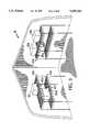
- FIG. 4illustrates an AC plug for connecting an electronic tag of a device to the network via the engagement of the plug with an AC power strip.
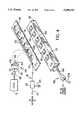
- FIG. 5is an exploded view of the AC plug of FIG. 4.
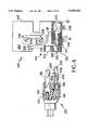
- FIGS. 6-8show an alternative embodiment of an AC plug and AC outlet for connecting an electronic tag of a device to the network.
- FIGS. 6A and 6Bare alternative embodiments of the AC outlet shown in FIG. 6.
- FIGS. 9 and 10illustrate a modification to the AC plug and AC outlet of FIGS. 6-8.
- FIGS. 11 and 12are exploded views of adapters for mounting an electronic tag to a standard AC plug.
- FIGS. 13-15show alternative embodiments of AC outlets connected to a communication link of the network.
- FIG. 16illustrates the use of an AC outlet with a non-AC, auxiliary connector, both of which serve one or more communications links of the network.
- FIGS. 17-19show an auxiliary connector in detail.
- FIG. 20shows an AC outlet used with other non-AC, auxiliary connectors, all of which serve one or more communication links of the network.
- FIG. 21illustrates the use of the AC power lines of a facility to form all or part of the network.
- FIG. 22shows an electronic tag with internal memory mounted to an AC plug.
- FIG. 23illustrates a second connector mounted to the plug for accessing the electronic tag.
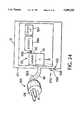
- FIGS. 24 and 25show further uses of the electronic tag.
- FIG. 26is an exploded view of an accessory for reading the electronic tag via an input port of a computer.
- FIG. 27illustrates another embodiment of a system for monitoring an inventory of devices through the use of a network.
- FIG. 1is a simplified block diagram of a system 10 for managing an inventory of multiple portable devices 12a-12d (designated generally as 12) in a facility, such as a hospital, by determining the locations and conditions of devices 12 on a network 14 of communication links, designated generally as 16.
- Each communication link 16is uniquely addressable and corresponds to a location in the hospital.
- communication links 16a, 16b, 16care assigned uniquely addressable areas of a storeroom 18, while other communication links 16 (not separately shown) correspond to other uniquely addressable locations (such as additional storerooms or patient rooms).
- a node 20 associated with storeroom 18receives communication links 16a, 16b, 16c at a corresponding set of ports 22, and provides an interface to network 14 via a network branch 24.
- Communication links 16a, 16b, and 16ccorrespond to various conditions of devices 12 stored in room 18.
- communication link 16ais associated with a storeroom area in which devices 12a, 12b that are ready for use are placed.
- Devices to be cleaned(such as device 12c) or repaired (e.g., device 12d) are disposed in other storeroom areas, each of which is assigned a communication link 16b, 16c.
- These areasare, for example, different shelves or sets of shelves in storeroom 18 (FIG. 3).
- network 14typically includes many more communication links 16 and nodes 20 for serving several additional, uniquely addressable locations in the hospital. Simply put, one or more communication links 16 are assigned to a sufficient number of rooms or other areas in the hospital at which devices 12 are likely to be stored or used to allow system 10 to track the locations and/or the conditions of the hospital's entire inventory of portable devices 12 to whatever level of detail is desired.
- Examples of such devices 12 in a hospital settinginclude patient care devices such as infusion pumps, vital signs monitors, sequential compression devices, pacemakers, and EKG machines, as well as other types of devices (e.g., electric blankets, wheelchairs, and carts for carrying bulky patient care devices).
- patient care devicessuch as infusion pumps, vital signs monitors, sequential compression devices, pacemakers, and EKG machines, as well as other types of devices (e.g., electric blankets, wheelchairs, and carts for carrying bulky patient care devices).
- Every device 12 that is to be tracked(e.g., devices 12a-12d) is equipped with a corresponding electronic tag 30a-30d (designated generally as 30) that uniquely identifies device 12.
- Tag 30is any electronic data label or carrier having the appropriate electrical characteristics for the functionality described below.
- One such electronic data labelis the "touch memory” or "silicon serial number” manufactured by Dallas Semiconductor Corporation of Dallas, Tex. under numerous part numbers (e.g., DS1990-DS1994 and DS2401); these devices are typically packaged in a stainless steel can (described below), but of course other parts having similar functionality but different form factors (i.e., packaging), such as that of a TO-92 transistor or a diode package, may be used instead.
- Properties of the "touch memory” (TM)which are advantageous for use with the invention include:
- the TMsare low cost, small in size, and have low power requirements
- each TMhas a unique identification number (discussed below);
- the TMscan be used as stand-alone information carriers or connected to a network for information transfer;
- multiple TMscan be read simultaneously over a communication link, and their presence on the communication link can be detected continuously;
- the TMssupport chip-to-chip communication (i.e., there is no requirement for proprietary readers);
- the TMsinclude a memory in addition to the unique identification
- the TMsare available in a stainless steel can or housing and can tolerate extreme physical, chemical, and thermal conditions;
- the TMssupport a so-called "one-wire" communication protocol (discussed below) which requires only a single wire in addition to a ground reference to allow data to be transferred to and from the TMs (a typical implementation of the protocol may include half-duplex, serial communication at data rates such as 16.3 Kbits/sec. or 115.2 Kbits/sec.);
- tag 30includes a unique identification in the form of a data structure 32 comprising a forty-eight bit tag address 34, an eight bit CRC code, and an eight bit family code, all of which are laser etched in memory of tag 30 during manufacturing.
- Tag 30also may include additional memory 33 (discussed below) for storing data (such as maintenance and ownership information) about device 12 and a battery 35 for powering memory 35.
- the components of tag 30are packaged 37 in any suitable way (e.g., in the aforementioned stainless steel can, a TO-92 transistor package, or an integrated circuit) and equipped with a pair of data ports 36, 38 for accessing data structure 32 (and memory 33, if provided).
- Each communication link 16includes a pair of wires--a data wire and a ground wire--(not separately shown), and is provided with a connector 40a, 40b, 40c (designated generally as 40) for connecting data ports 36, 38 of tags 30 across the wires of link 16.
- communication links 16 and connectors 40provide electrical connections between node ports 22 and tags 30 of devices 12 disposed in the location to which communication links 16 are assigned.
- storeroom 18is subdivided into areas that correspond to the different device conditions and which include one or more shelves for devices 12.
- Communication links 16a-16care physically wired to the shelves that they serve, and connectors 40a-40c are located on or near the shelves for receiving tags 30.
- connectors 40a-40care mounted on the fronts of the shelves, as shown; alternative placements include the bottoms of the shelves, above the shelves, or on the wall behind the shelves.
- tag-reading circuitry associated with each node 20communicates over the data wires of communication links 16 using a so-called “one wire protocol,” and employs a "divide and conquer" procedure to read data structures 32 of all tags 30 connected to each link 16. In this way, the tag-reading circuitry detects all devices 12 that are connected to its ports 22. This operation and the tag-reading circuitry are fully discussed in the '929 application and will not be repeated here.
- a user who places a device 12 in any locationneed do no more than place device 12 in the appropriate area (such as on one of the shelves shown in FIG. 3) and connect tag 30 of that device to a connector 40.
- the tag-reading circuitry associated with node 20reads data structure 32 and correlates it with the identity of the port 22 on which data structure 32 is read.
- the tag-reading circuitry associated with all nodes 20report this information to one or more host computers 60 (only one of which is shown) on network 14.
- Host computer 60maintains databases on all locations (and, where applicable, the conditions) of devices 12.
- the databasesare accessible by users (e.g., hospital personnel) at host computer 60, or at other computers 62 on network 14, and thus serve as highly valuable tools for assisting hospital personnel in locating stored devices 12 and managing the inventory of devices 12.
- the databasesare implemented using any suitable database management system, such as Microsoft "FoxproTM 2.5 Database Management System for DOS” or "Microsoft AccessTM 2.1 for Windows.”
- Reports of the locations and conditions of selected devices 12are generated by computers 60, 62 using the database information, and are transmitted over network branches 24 for use by output devices 64.
- Examples of output devices 64include computers for displaying the reports, printers for printing the reports, and facsimile equipment for faxing reports to selected destinations.
- Network computers 60, 62can also send messages that contain at least some of the information in the reports to a user. This may be done by telephone or by pager (not shown). All of these operations are described in detail in the '929 application and will not be repeated here.
- each connector 40includes an elongated, plastic housing equipped with a slot for receiving multiple tags 30 side-by-side. When the user slides a tag 30 into the slot, contact is made between tag data ports 36, 38 and the two wires of communication link 16.
- the elongated connectorincludes a set of resilient metal fingers that serve as the ground wire of communication link 16 and hold tags 30 in the slot.
- a connector for receiving multiple tags 30is a magnetic strip which holds tags 30 in place by magnetic attraction.
- each communication link 16is equipped with a number of parallel connectors, each for receiving and connecting one tag 30 across the wires of communication link 16.
- tag 30is mounted via a plunger mechanism to device 12, and is connected to communication link 16 simply by placing device 12 on a wire shelf configured to couple both wires across the tag.
- the present inventionprovides an alternative way of connecting a tag 30 of a device 12 to a network communication link 16 that combines the act of connecting device 12 to a power source (such as an AC power outlet) with the act of connecting tag 30 to communication link 16.
- a power sourcesuch as an AC power outlet
- tag 30is mounted to the AC plug of device 12 with which tag 30 is associated, either by embedding tag 30 into the plug or through the use of an adapter, and is accessible via one or more data contacts on the plug.
- each communication link 16is wired to an AC outlet and is engaged by the data contacts on the plug when the plug is inserted into the outlet.
- the userautomatically connects tag 30 (and hence device 12) to network 14 simply by performing the well-practiced step of connecting device 12 to the power source (e.g., "plugging-in” the device). Connection to network 14 is thus totally transparent to the user and requires nothing on the user's part in addition to the normal act of plugging in device 12 (e.g., to recharge storage batteries). Because users typically are trained to plug devices 12 into an electrical power connector or perform this act as a matter of routine (even when devices 12 are placed in storerooms), the rate of compliance by device users is likely to be high, which translates into highly accurate device tracking using the techniques of the '929 application.
- the AC plug 100 of each device 12is modified in any one of several ways (discussed below) to include a tag 30.
- tag 30may either be mounted directly to or within plug 100 or may be connected to plug 100 via an adapter. In either case, the normal AC power connections between device 12 and blades 102 and ground pin 104 on plug 100 via cord 98 are not disturbed, and plug 100 retains the form and size of a standard AC plug, thereby remaining fully compatible with standard AC outlets.
- Data port 36 of tag 30is connected to a data contact 106 (described below) mounted on the face of plug 100 to establish an electrical path to tag 30 that is separate from the AC connections provided by AC line and neutral blades 102 and ground pin 104.
- Ground pin 104 of plug 100is electrically connected to tag data port 38.
- a single accessory connection data contact 106)is added to a standard-configuration AC plug 100 to provide the interface to tag 30 and to allow data structure 32 and/or memory 33 (FIG. 2) to be accessed from outlet 110 using the aforementioned one wire protocol.
- data contact 106is positioned above and centered between AC blades 102, and is oriented opposite ground pin 104.
- AC outlets 110are suitable for use with plug 100 (as well as with other embodiments of plug 100 discussed below). These designs include single AC outlets, duplex outlets, and multi-outlet power strips. Of these various designs, some are intended to permit use of plug 100 and alternative embodiments thereof with minimal modification to the receptacle, while others require that the receptacles be modified more extensively.
- FIG. 4shows an embodiment in which AC outlet 110 is a power strip containing a series of standard female AC sockets or receptacles 112, each of which includes a pair of AC terminals 114 and a ground terminal 115 configured to receive AC blades 102 and ground pin 104 of plug 100.
- Outlet 110is fitted with a nonconductive plastic or plexiglas mask 116 having a set of apertures 118 for receiving receptacles 112.
- Mask 116thus exposes receptacles 112 for connection to AC plugs 100.
- receptacles 112are elevated slightly so as to be approximately coplanar with the upper surface of mask 116.
- a model 4619 power stripavailable from Waber Inc., in Mt. Laurel, N.J. has sockets elevated by 3/16" above the surface of the power strip, allowing sufficient room for mask 116.
- Mask 116includes a series of data contacts 120 spaced along a data wire 122 that is connected to communication link 16 at a data port 124.
- Data wire 122is either etched on the upper surface of mask 116 or is laminated within mask 116.
- Communication link 16is connected to network 14 via node 20 as discussed above and in the '929 application.
- Outlet 110is equipped with a power cord 126 and plug 128 for connecting receptacles to a source of AC power (not shown) in the conventional way.
- Ground potential 125a for outlet 110generally is the same ground potential 125 to which node 20 and the ground wire of communication link 16 are referenced, but the ground wire and potentials 125, 125a may or may not be physically wired together.
- Each data contact 120is oriented with respect to AC terminals 114 and ground terminal 115 to ensure that a secure connection is made with data contact 106 when AC plug 100 is inserted into receptacle 112. Due to the three-pronged nature of AC plug 100, data contact 106 is automatically aligned with data contact 120 of mask 116 whenever plug 100 is properly inserted into receptacle 112. This allows tag-reading circuitry associated with node 20 to access data contact 106 via communication link 16 to exchange data with tag 30 (e.g., read tag data structure 32 or write data to tag memory 33--see FIG. 2).
- tag 30e.g., read tag data structure 32 or write data to tag memory 33--see FIG. 2.
- AC plug 100that is modified to incorporate a tag 30 within it is shown. It will be appreciated that AC plug 100 contains both standard AC connections (i.e., line, neutral, and ground), as well as the connections to tag ports 36, 38, all integrally formed within a single housing 154. AC plug 100 thus is suitable for connection to any standard AC power cord 98 attached to a device 12.
- standard AC connectionsi.e., line, neutral, and ground
- package 37 (FIG. 2) of tag 30is in the form of a transistor package 130 (Dallas Semiconductor part no. DS2401) equipped with a pair of wires 130a, 130b which are electrically connected to tag data ports 36, 38 within package 130.
- Tag package 130is fixed to a lower surface 131 of an insulating plate 133.
- Data contact 106(FIG. 4) is provided by a metal screw 132 that passes through a hole 136 in the front face 135 of plug 100 and a corresponding opening in plate 133, and is secured to a nut 138 welded to wire 130a.
- AC plug 100also provides for connection of a ground wire 148, an AC neutral wire 150 and the AC line voltage wire 152 of power cord 98 to ground pin 104 and AC blades 102 in standard fashion.
- Wires 148-152pass through openings in plate 133 for this purpose and are secured by screws 158 to respective clamps 160 that serve ground pin 104 and AC blades 102.
- wire 130b of tag housing 130is connected to ground pin 104 and ground wire 148 by the connection between screw 158 and clamp 160 associated with ground wire 148.
- Housing 154covers the entire plug assembly and threadably receives a pair of screws 156 which pass through front face 135.
- Plug 100 and its AC componentsincluding plate 133, face 135, housing 154 and mounting hardware 1565, 158, 160) are available from Eagle Corporation of Long Island City, N.Y.
- the length of screw 132 and the position of tag housing 130 and wire 130aare such that the head of screw 132 protrudes slightly from plug face 135 when plug 100 is not engaged with an AC outlet.
- Wire 130ais sufficiently stiff to act as a leaf spring, resisting the depression of screw 132 into housing 154 (in the direction of arrow 140).
- screw 132is essentially a spring-loaded pin for engaging data contact 120 (FIG. 4).
- plug 100is inserted into a receptacle 112 of outlet 110, the head of screw 132 engages data contact 120 on mask 116 and, due to the slight protrusion of the screw head from plug face 135, is depressed in the direction of arrow 140.
- the resiliency of wire 130aresists the movement of screw 132 to provide a firm connection between screw 132 and data contact 120 on mask 116, thereby providing a positive, reliable connection between tag 30 and communication link 16.
- spring-loading screw 132does not interfere with the normal insertion of plug 100 in any AC outlet--whether the outlet is equipped with a data contact 120, or not.
- the head of screw 132retreats within hole 136 to allow plug face 135 be placed flush against the face of the outlet.
- the resiliency of wire 130ais insufficient to overcome the force of the connection between the plug and outlet, and thus does not cause plug 100 to "back out" of the outlet.
- screw 132may be provided in other ways.
- One possibilityis secure tag wire 130a in a fixed position and interpose a helical spring between the shaft of screw 132 and nut 138.
- screw 132may be fixed rigidly in position, rather than being spring loaded.
- Data contact 120can be recessed somewhat in the upper surface of mask 116 (FIG. 4), if desired, to allow plug 100 to be flush with the upper surface of mask 116.
- the spring-loaded componentmay be provided on the AC outlet 110 rather than on plug 100.
- data contacts 120 of outlet 110may each be implemented as a spring-loaded pin.
- plug 100may include a female data contact 106--such as a socket--in place of the male pin shown in FIG. 5.
- data contact 106may be flush with the face of plug 100.
- data contact 106need not be positioned opposite to ground pin 104 between AC blades 102--any suitable radial or angular position may be used.
- multiple contacts 106can used to provide additional accessory communications connections.
- both data port connections to tag 30may be positioned as discrete contacts which are entirely separate from AC blades 102 and ground pin 104.
- the connection between data contacts 106, 120may be momentary, rather than continuous.
- Tag 30need not be physically located within the plug. Any suitable location will do.
- tag 30can be incorporated in power cord 98 or housed in device 12 itself, simply by suitably extending electrical connections to data ports 36, 38 (FIG. 2).
- tag 30may be located in various places outside the housing of plug 100, or may be secured to the AC plug through an adapter (examples of such an adapter are shown in FIGS. 11 and 12).
- communication link 16may be wired to an outlet other than power strip 110.
- tag 30(housed in transistor package 130, discussed above) is molded within a plastic AC plug 200 of the kind that has a hollow, U-shaped ground pin 204 centered beneath AC line and neutral blades 202.
- a plastic AC plug 200of the kind that has a hollow, U-shaped ground pin 204 centered beneath AC line and neutral blades 202.
- One example of such a plug 200is an Eagle Corporation NEMA 5-15P hospital plug, available as part number 88020270 from Panel Components Corporation of Oskaloosa, Iowa.
- Wires 130a, 130bextend from the housing 201 of plug 200 into an elongated cavity 205 defined by ground pin 204 within suitable nonconductive medium 206, such as a hollow, compressible sheath (FIGS. 7 and 8) to insulate them from ground pin 204 while also providing secure attachment to ground pin 204.
- suitable nonconductive medium 206such as a hollow, compressible sheath (FIGS. 7 and 8)
- the free end of wire 130bis soldered or otherwise attached to an interior surface of ground pin 204 at ground contact 207.
- the free end of wire 130ais attached to a metal data contact 208 positioned outside of sheath 206. As shown by FIG. 8, contact 208 is insulated from, and approximately centered with respect to, the sides 204a of U-shaped ground pin 204 and is resiliently supported beyond ground pin edges 204b.
- AC power cord 98enters plug housing 201 in the usual way.
- AC line wire 148 and neutral wire(not shown) are fixed to blades 202 (only one of which is shown).
- AC ground wire 150is secured to ground pin 204.
- AC outlet 220includes a pair of sockets 222 (only one of which is shown in detail) each of which is configured to connect finger 208 (and hence tag 30) to communication link 16 and contact 207 to ground, as well as join AC blades 202 to AC terminals 224 and engage ground pin 204 with ground terminal 226 in the usual manner, when AC plug 200 is properly inserted therein.
- An example of a typical AC outlet that can be modified in this wayis an Eagle Corporation NEMA 5-15R hospital grade socket, available as part number 88020290 from Panel Components Corporation of Oskaloosa, Iowa.
- Ground terminal 226is equipped with a data contact 230 mounted on a lower wall 232 of terminal 226 to engage finger 208 in a sliding fashion when ground pin 204 is inserted into receptacle 222.
- data contacts 208, 230should be arranged to avoid short circuiting between data contact 230 and ground in the event that a plug that is not equipped with a data contact 208 on its ground pin is inserted in receptacle 222.
- Communication link 16is wired within wall 232 and electrically connected to data contact 230.
- Communication link 16is also soldered 241 to a terminal 242, which provides an external connection to node 20 (not shown).
- AC line and neutral terminals 224are internally connected to lugs 236 on the sides of the outlet housing 240 in the usual way.
- an AC ground connectionis made between a contact 227 on terminal 226 and ground lug 238 via wire 229.
- Lugs 236, 238are secured to the AC wiring of the facility in a conventional manner, and hence these connections are not shown.
- Ground lug 238provides the ground connection for the two wire communication link 16. Terminals 242 and lugs 238 of a series of outlets 220 may be wired together in a "party line” or “daisy chain” fashion so that a single communication link 16 can serve, e.g., all of the outlets 220 in a room or set of rooms. This embodiment is explored in detail below with reference to FIG. 13.
- node 20may be mounted within outlet housing 240. In this case, an external connection for communication link 16 is not needed (although it certainly may be provided).
- the outputs of node 20are connected to a pair of terminals 231 on housing 240 for external access.
- FIG. 6Billustrates yet another embodiment, useful when node 20 is enabled to communicate over the AC power lines of the facility.
- An embodiment in which node 20 communicates over the AC power linesi.e., the AC power lines serve as part or all of network 14
- the outputs of node 20are applied by a pair of wires 250, 252 to the AC line and neutral terminals 236 of outlet 220.
- tag 30can alternatively be mounted within cavity 205 of ground pin 204, rather than within the plug housing.
- AC plug 200'has such a configuration.
- tag package 130'is an integrated circuit (e.g., a Dallas semiconductor DS1990a, or an alternative component with similar functionality) suitable for surface-mount applications on miniature printed circuit boards (the approximate dimensions of package 130' are 0.100 inches in length X 0.062 inches in width X 0.040 inches in height).
- Tag contact 130ais connected to an elongated conductor 260 encased within a suitable nonconductive medium 262 (such as an epoxy body) that is bonded to sides 204a of ground pin 204.
- Tag contact 130bis grounded to an interior surface of ground pin 204.
- Tag wires 130a, 130bare insulated to avoid short-circuiting to each other or to ground pin 204.
- Mounting medium 262insulates conductor 260 from ground pin 204 and, together with the connections of wires 130a, 130b, holds tag package 130' in place within cavity 205.
- Conductor 260is positioned so that its lower surface protrudes slightly beyond the plane defined by the edges 204b of sides 204a.
- Receptacle 222' used in conjunction with plug 200'includes a data wire 270 supported vertically within ground terminal 226'.
- Data wire 270is connected to node 20 (which can be mounted within or externally to receptacle 222') by communication link 16, which is mounted within a lower wall of receptacle 222' in a manner similar to that shown in FIG. 6.
- Data wire 270protrudes into ground terminal 226' only by an amount sufficient to contact conductor 260.
- Wire 270is resilient and thus bends as plug 200' is inserted and returns to the vertical orientation when plug 200' is withdrawn.
- other techniquesmay be used to provide a suitable electrical connection between data contact 270 and conductor 260.
- conductor 260makes a brushing contact with data wire 270, thereby connecting tag 30 to communication link 16.
- the ground connection to wire 130bis made in the same manner as described above for FIG. 6.
- Any plug 200, 200' with hollow ground pin 204is thus easily modified for communication over network 14 simply by placing tag package 130' and conductor 260/mounting medium 262 assembly in cavity 205 of ground pin 204 and making the signal and ground connections described above.
- the plugneed not have a U-shaped ground pin 204.
- plug 200'may have a ground pin 204 with a circular cross-section.
- tag package 130'(or 130) is placed in an insulating sheath (such as sheath 206, FIG. 8) and inserted into cavity 205 during the assembly of plug 200'.
- Tag wire 130ais passed through a small hole in sheath 206 and soldered to a metal region on the underside of ground pin 204 that is insulated from the remainder of ground pin 204 (e.g., by a ring of plastic) to provide an electrical path to data port 36 of tag 30 (FIG. 2).
- Tag wire 130b(and thus tag data port 38) passes through a second opening in sheath 206 and is connected to another, grounded region of pin 204, as discussed above relative to FIGS. 6-8.
- ground pinis used to connect tag data ports 36, 38 to the communication link and ground
- data wiree.g., 270
- an unmodified ground pine.g., 204 which does not contain components (such as 260, 262 or 130, 130a or 130b), or to a cylindrical ground pin, such as that shown protruding from plug housing 301 in FIGS. 11 and 12.
- an adapter 300 that contains a tag 30is used to retrofit an ordinary AC plug 301 with tag 30.
- Adapter 300includes a male AC plug 302 at one end for insertion into any of the receptacles discussed in this application, and a female AC socket 304 at an opposite end for receiving plug 301 attached to a power cord 98 of a device 12 (not shown).
- Plug 301is glued to socket 304 if adapter 300 (and hence tag 30) is to be permanently associated with plug 301.
- Tag 30is mounted in a metal, can-shaped package 310 described below and in the '929 application) the upper surface 312 and lower surface 314 of which provide electrical connections to data ports 36, 38 (FIG. 2).
- Package 310is sandwiched between a front support plate 308 and a rear support plate 309. Plates 308, 309 are maintained in position with respect to male AC plug 302 and AC socket 304 by screws 350.
- a thin metal signal plate 318is captured between package 310 and support plate 408 and is in electrical contact with surface 314 of package 310.
- a helical spring 322is soldered to a free end 320 of signal plate 318, which is notched to receive spring 322.
- One end of spring 322is attached to a nut 324, which in turn is permanently fixed to socket 304.
- the opposite end of spring 322is attached to a second nut 330, which threadably receives a screw 332.
- adapter plug 302 and socket 304are made by insulated wires 338 (only one of which is shown) the ends of which are secured by screws 352 and clamps (not shown) in the usual manner.
- ground terminal 317 of socket 304(to which tag data port 38 is connected via plate 313 and tab 316) is electrically connected to ground pin 319 of plug 302.
- Adaptor 300is assembled by placing all internal components in a housing 346 as discussed above, and fitting the ends of the housing with male plug 302 and socket 304 using an adhesive. Holes 334, 348 in male plug 302 are aligned with notches in support plates 308, 309. Screws 350 are passed through apertures 334, 348 and support plates 308, 309 and are threaded into socket 304 to securely hold the internal components together. Housing 346 may be provided with an access port 347 (e.g., a portion of housing 346 that can be removed) for exposing tag package 310 and allowing it to be removed and replaced with an new (or repaired) tag 30 without disassembling adapter 300.
- an access port 347e.g., a portion of housing 346 that can be removed
- AC plug adapter 300i.e., with tag 30 mounted therein
- adapter 300is a NEMA 5-15R in-line connector, manufactured by Eagle Corporation and available as part number 88020280 from Panel Components Corporation.
- screw 332 and spring 322are such that the head of screw 332 protrudes slightly from an aperture 334 in the face of male plug 302--thus, it will be appreciated that screw 332 serves as a spring-loaded pin for connecting tag 30 to, for example, a data contact (FIG. 5) of a communication link 16.
- adapter 300/plug 302are installed in, e.g., receptacle 112 of outlet 110 (FIG. 5)
- screw 332is pushed into adapter 300 (that is, in the direction indicated by arrow 336).
- Spring 322compresses against the motion of screw 332, thereby firmly establishing the electrical connection between screw 332 and data contact 120.
- an alternative plug adapter 300'houses a transistor-type tag package 130 of the kind shown in FIG. 5.
- Tag wire 130ais soldered to spring 322 at approximately the midpoint thereof.
- Tag wire 130bis electrically connected to the conductor of insulated wire 338 that joins ground leads 317, 319 of adapter plug 302 and socket 304.
- the assembly of adaptor 300'is otherwise identical to the assembly of adaptor 300.
- tag wires 130a, 130bmay be removably connected to spring 322 and wire 338 (e.g., in a pin-in-socket manner) to allow tag package 30 to be removed and replace.
- Housing 346may be provided with an access port 347 for this purpose.
- spring 322may be eliminated, and the resiliency of tag wire 130a relied upon to spring-load screw 332. This construction is discussed above with reference to FIG. 5.
- plug configurationsare within the claims. Indeed, a variety of plugs other than an AC power plug can be modified for use with the invention. For example, line power wiring plugs conforming to standards of other countries can be fitted with tags 30 according to the invention.
- FIG. 13shows a pair of AC outlets 410a, 410b (generally referred to as 410) for connecting tags 30 of plugs (not shown) inserted therein to a communication link 16 connected between outlets 410a, 410b in "daisy-chain" fashion. (It will be appreciated that more, or fewer, outlets 410 can be connected to communication link 16 in this manner.)
- Each outlet 410is retrofitted for connection to communication link 16--the receptacle assemblies 412 (only one of which is shown) of outlets 410 are not modified in any way.
- a thin plastic mask 414(similar to mask 116 of FIG. 4) that includes a pattern of conductive traces 416 which terminate in a pair of data contacts 418 is mounted to outlet faceplate 420 by four corner screws 422.
- a pair of apertures 424 in mask 414expose the plug apertures of faceplate 420 (which is mounted to receptacle assembly 412 in the usual way, by a screw 424).
- Mask 414covers screw 424 to avoid potential contact between trace 416 or contact 418 and screw 424, as well as all other pathways to ground.
- Data contacts 418are positioned above each aperture 424 in the same way that contacts 120 are positioned on mask 116 (FIG. 4).
- Communication link 16is wired through a small hole 426 in the corner of faceplate 420 and connected to terminal 428 of trace pattern 416 on rear surface 429 of faceplate 420.
- Hole 426may be cut in a standard faceplate 420; alternately, hole 426 (or a punchout therefor) may be formed during manufacture of faceplate 420.
- An extension 430 of communication link 16is wired from terminal 428, through hole 426 to the next outlet (e.g., 410b) in the chain.
- a service loop in communication link 16 and extension 430provides easy axis to terminal 428 for servicing.
- Extension 430may be secured by adhesive-backed tape along the outer surface of a wall 432 on which outlets 410 are mounted, or, if desired, can be hidden from view behind wall 432 (this is shown by extension 430' in dashed lines).
- node 20is mounted, for example, within an AC housing 434 that is inserted in another AC outlet (not shown) to enable node 20 to communicate with host computer 60 (FIG. 1).
- outlet 410'includes receptacle assembly 412' modified to include node 20 therein.
- receptacle assembly 412'includes a pair of data contacts 440 connected to node 20 through communication link 16.
- Each data contact 440is a metal pin that is positioned above an individual receptacle 442 and protrudes through a corresponding hole 421 in faceplate 420+.
- Data contacts 440are flush with the outer surface of faceplate 420' for engagement with a data contact of a tag-equipped AC plug (e.g., contact 106 of plug 100--FIG. 4).
- node 20If the AC power lines of the facility are used in network 14, the outputs of node 20 are connected to AC line terminals 444 and ground terminal 446 (as needed) of receptacle assembly 412'. Node 20 is also grounded to terminal 445. (The connections to the AC power line that serves outlet 410' are not shown.)
- outlet 410'may be daisy-chained to other outlets (e.g., outlets configured similarly to outlet 410' but not equipped with a node 20, or outlets 410 shown in FIG. 13) by providing an external contact for communication link 16 (as shown in FIG. 6).
- outletse.g., outlets configured similarly to outlet 410' but not equipped with a node 20, or outlets 410 shown in FIG. 13
- Thisenables node 20 in outlet 410' to serve multiple devices 12 in a so-called "multi-drop" configuration.
- any of the AC outlets described herein configured to receive a tag-equipped AC plug and connect tag 30 to a communication link 16may also be used with one or more auxiliary, non-AC power connectors 450 for receiving tags 30.
- auxiliary connectors 450are described in the '929 application and have been summarized above.
- FIGS. 17-19Another example of an auxiliary connector 450 is shown in FIGS. 17-19 and described below.
- auxiliary connector 450is used with tags 30' that are tethered to devices 12 by non-electrical cables 452 (e.g., wire or plastic cords that are secured to the housings of devices 12).
- tags 30'are mounted in a metal housing that provides access to data ports 36, 38 (such as housing 492 described above and shown in FIG. 18 below) and that is secured to a plastic or other non-conductive card 454 secured to tether 452. Securing tag 30'/card 454 to connector 450 connects data ports 36, 38 across the pair of wires 16 1 , 16 2 of an extension 16' of communication link 16.
- Mask 116 and outlet 110are modified from the configuration shown in FIG. 4 to include a connector 456 for receiving a compatible connector 458 on communication link extension 16'.
- Connectors 456, 458are, for example, a female phono jack and a male phono plug, respectively. When connectors 456, 458 are engaged, data wire 16 1 of extension 16' is connected to data wire 122, and thus to node 20 via communication link 16.
- an insulated feed 460is provided through mask 116 and the housing of outlet 110 to connect data wire 16 2 to the common ground connection used by receptacles 112 and plug 128.
- tags 30'are connected by extension 16' to the same communication link 16 (and thus the same port 22 of node 20) to which tags 30 are connected by the engagement of plugs 100 and receptacles 112.
- communication link extension 16'may be connected to a different port 22 of node 20, simply by providing a separate port on mask 116 for jack 456. Among other advantages, this would allow host computer 60 to distinguish between devices 12 connected to outlet 110 from devices 12 linked to connector 450.
- auxiliary connector 450includes an elongated board 470 that includes a series of axially spaced, circular slots 472, each of which is sized to receive a tag 30' on a card 454.
- Board 470is comprised of two strips 474, 476 of plastic that are laminated together (FIG. 19) and capture therebetween data wire 16 1 of communication link extension 16', which is received at terminal 478 and extends along the length of board 470.
- Slots 472are formed in strip 474 to expose wire 16 1 .
- Wire 16 2 of communication link extension 16'is electrically connected to a metal backplane 480 which is in turn grounded at ground terminal 482.
- a series of metal spring clips 484are mounted between board 470 and backplane 480, with one of the resilient edges 248 of each clip 484 being aligned with each slot 472.
- Spring clips 230are 16 mm, 5/8" medium SKU 103549 binder clips, available from Staples Corporation of Framingham, Mass.
- Each clip 484is glued to the rear surface of strip 476 and is soldered to backplane 480, which extends above the upper surface 488 of each clip 484 to provide additional support for clips 484.
- Strip 474is beveled 490 at the lower edge of each slot 472 to ease insertion of tag 30' and card 454 in the orientation shown in FIG. 18.
- Tag 30'is contained in a metal housing 492 of the kind described above and in the '929 application.
- Tag data ports 36, 38(FIG. 2) are in electrical contact with upper and lower surfaces 494, 496, respectively, of housing 492.
- Tag 30'is inserted into slot 472 by orienting tag housing 492 and card 454 so that surface 494 faces connector 450, inserting the front edge 498 of card 454 under clip 484, and then sliding housing 492 over edge 490 into slot 472.
- card 454forces front edge 486 of clip 484 away from board 470.
- clip 484springs back towards board 470 to firmly engage memory surface 496 of tag housing 492 and hold card 454 in place.
- clip 484The resiliency of clip 484 firmly holds tag housing 492 in place in slot 472 so that surface 494 is fixed against data wire 16 1 .
- Front edge 486 of clip 484establishes a secure electrical connection with ground plane 480 (and hence wire 16 2 ) via the electrical path provided by metal clip 484.
- tag 30'can be accessed by node 20 in the manner discussed above and in the '929 application via communication link extension 16'.
- AC outlet 500is similar to power strip 110 (FIG. 4) in that outlet 500 provides a set of data contacts 502 for engaging data contacts 106 of tag-equipped AC plugs 100 (FIG. 4) that are inserted into receptacles 504.
- communication link 16extends through the housing 506 of outlet 500 to a set of data contacts 502 disposed on the upper surface 508 of housing 506 at each receptacle 504.
- node 20is disposed within housing 506 and receives communication link 16 at one of its ports 22. Node 20 communicates over the AC power lines of the facility (which serve as network 14, not shown), and is discussed in more detail below.
- outputs 510 of nodeare connected to the AC power wires of power cord 512 and the AC power blades of plug 514 for connection to network 14.
- Outlet 500includes two additional auxiliary connectors 520, 522, each of which is connected via a communication link 16 to a port 22 of node 20.
- Auxiliary connectors 520, 522 and data contacts 502may be connected to the same node port 22, or they may be linked to different node ports 22 through their own communication links 16 (as shown), or to any selected combination of node ports 22.
- Auxiliary connector 520is, for example, an RCA female phono jack of the kind discussed above.
- a connector of this sortis particularly useful for a device 12 on which a tag housing 492 (FIG. 18) is permanently mounted. Examples of such a device 12 include such non-AC powered devices as pacemakers, DC or battery powered machines, or mechanical devices such as wheelchairs.
- Tag 30 (not shown) in housing 492is read by a touch-and-hold probe 534 (available from Dallas Semiconductor) held by a plastic grip 536 on the end of a two-wire cord 532.
- a phono plug 530 on the opposite end of cord 532mates with auxiliary connector 520.
- Probe 534includes a snap and hold fastener that securely grips tag housing 492 and connects tag data ports 36, 38 to the wires of cord 532, and thence to communication link 16 and ground, respectively, in outlet 500 via the connection between plug 530 and auxiliary connector 520.
- Auxiliary connector 522is a badge reader configured to read a tag 30 mounted via housing 294 (FIG. 18) on an employee ID badge.
- a badge readeris a DS 9092 Touch Probe available from Dallas Semiconductor.
- badge reader 522allows a user to enter an employee identification number (i.e., data structure 32 of tag 30) into system 10 whenever he or she connects a device 12 to outlet 500.
- each node 20 that communicates with power line network 14'includes an AC line transceiver 550 that serves as an interface between branches 552 of AC power lines 14' and tag reading circuitry 554.
- Tag reading circuitry 554reads data structures 32 (FIG. 2) of all tags 30 connected to communication links 16 served by node 20 in the same manner as discussed above and in the '929 application.
- Transceiver 550converts the data signals produced by tag reading circuitry 554 into suitable form (such as differential or common mode) for transmission over the AC line and AC neutral wires of power line network 14'.
- Transceiver 550 and tag reading circuitry 554are available together as a PLC-10 power line control module, model 56010, available from Echelon Corporation in Palo Alto, Calif.
- Host computer 60is also equipped with an AC line transceiver 556 that receives the data signals from a branch 552 of AC power line network 14' and converts them to a form suitable for use by host processing and memory 558.
- Transceiver 558is available from Echelon Corporation.
- Host processing and memory 556is identical to that discussed above and in the '929 application, and communicates with output device 64 (or other computers or workstations of system 10) over, e.g., network branch 24.
- Network 14'is easily and inexpensively implemented in a building with power line network (which has been optimized for such powerline communication), without installing any new wiring in the building. This is done by distributing any of the AC outlets described in this application in key inventory locations in the building (e.g. in storerooms 18), installing AC line transceivers 550, 556 in nodes 20 and host computer 60, and providing each device 12 in the inventory with any one of the tag-equipped AC plugs described herein.
- tag 30may include a memory 33 (and battery 35, not shown) in addition to data structure 32 (FIG. 2). Examples of such a tag include the aforementioned Dallas Semiconductor DS1991-DS1994 touch memories. Data ports 36, 38 also serve to connect memory 33 between data contact 106 and ground pin 104 of plug 100. Host computer 60 (FIG. 1) writes data to memory 33 via communication link 16 and the connection between data contact 106 and data contact 120 when plug 100 is inserted in a receptacle 112 of outlet 110 (FIG. 4).
- Tag 30can optionally be accessed by a secondary connector 560 connected to tag 30 in parallel with data contact 106.
- Secondary connector 560includes housing 492 (FIG. 18) that does not contain a tag, but includes data and ground wires 561, 562 connected to surfaces 494, 496. This "empty" housing 492 is available from Dallas Semiconductor as part no. DS9092R.
- Tag 30(also disposed in a housing 492) is mounted in a conventional coin cell battery holder 563 embedded within the housing of plug 100. Terminals 563a, 563b of holder 563 engage data ports 38, 38 via surfaces 494, 496, and also receive wires 561, 562.
- terminal 563ais wired to data contact 208 (FIGS. 6-8) on ground pin 204; terminal 563b is grounded at ground contact 207.
- tag 30is accessible from both communication link 16 (as described above) and secondary connector 560. This allows a user to exchange information with tag 30 using a touch and hold probe 534 (FIG. 20) or other suitable reader.
- Tag 30may be removable from the housing of plug 100 by providing an access port 564, which may be equipped with a lid or the like for covering tag 30 and assisting retaining tag 30 within the housing.
- access port 564can be open, and the friction provided by terminals 563a, 563b relied upon to retain tag 30.
- tag 30may be equipped with an LED 565 or other suitable illumination device that can be energized by circuitry in tag 30 in response to a command received from host computer 60 over communication link 16. This is particularly useful if the plug housing is translucent. Among other advantages, illuminating LED 565 "flags" device 12 associated with tag 30 to aid a user in selecting device 12 from among numerous other devices 12 in the same location.
- tag memory 33is additionally connected to a microprocessor 567 in a device 12 through an interface 566 connected to memory 33 through leads 568.
- Tag 30, interface 566, and leads 568are available together as a Dallas Dual Ported Touch Memory DS2404-001 (reference: “50 Ways to Touch Memory, Second Edition", October, 1992, Dallas Semiconductor, incorporated herein by reference).
- tag 30is located within device 12 (rather than in AC plug 100) to minimize the length of leads 568.
- Data contact 106is connected to tag 30 by a wire 569 that extends through cord 98, which is either permanently fixed to device 12 (as shown) or connected thereto with a modular plug.
- tag 30can alternatively be placed in any of the positions described above.
- host computer 60(FIG. 1) can capture data about the operation of device 12 stored by microprocessor 567 in memory 33 (e.g., run-time information).
- host computer 60may control device 12 over network 14 by communicating with microprocessor 567 through tag 30.
- host computer 60may load operating parameters for device 12 in memory 33, which are used by microprocessor 567 to adjust the operation of device 12 accordingly.
- a secondary connector 570can be mounted to an exterior surface 571 of device 12 to provide the parallel access discussed above. Housing surface 494 is linked to wire 569, while housing surface 496 is grounded. As a result, secondary connector 570 is connected to tag 30 in parallel with data contact 106 and the ground pin of plug 100.
- tag 30is mounted externally to device 12 in a block 572 that is secured (permanently or otherwise) to an exterior surface 573 of device 12.
- Data ports 36, 38 of tag 30are wired to a modular connector 574 on block 572.
- a mating connector 575receives data wire 569 and ground wire 576 from cord 98 via sheath 577.
- a modular power connector 578 on cord 98engages a like power connector 579 on device 12 to supply AC power thereto, and provides the device-ground connection for wire 576.
- connectors 574, 575which are, e.g., RJ-11 type connectors
- tag 30is accessible via a parallel, secondary connector (such as empty housing 492), which is wired as discussed above to the electrical connections of tag 30.
- connectors 575, 578can also be used with, e.g., the arrangement shown in FIG. 23.
- secondary connector 570may be mounted on a block that includes a modular connector 574 for receiving connector 575.
- connectors 578, 579would also provide the electrical connections to tag 30.
- tag 30 mounted to any of the AC plugs described hereincan be read directly by a personal computer with accessory 580.
- Accessory 580includes a female AC receptacle 582 that receives AC plug 100 but lacks wiring for applying AC power to plug 100--in other words, receptacle 582 is a "dummy" AC outlet.
- the AC line and neutral terminals 584 and ground terminal 586receive blades 102 and ground pin 104 (FIG. 4) of plug 100 so that data contact 106 of plug 100 is in alignment with a data contact 588 mounted in receptacle 582.
- Data contact 588is in the form of screw positioned above and centered between the AC terminals 584.
- the head of data contact screw 588protrudes slightly from the face of receptacle 582.
- the opposite end of data contact screw 588is threaded into a nut 590 permanently fixed to a spring 592 that is soldered to data wire 594.
- the opposite end of spring 592is rigidly secured to a nut 596 mounted on receptacle body 598.
- screw 588(which serves as data contact 106) is spring mounted within receptacle 582.
- Data wire 594provides an electrical connection between data contact screw 588 and a computer serial port connector 600 through a cable 602.
- Ground terminal 586is electrically connected to ground wire 604, which also runs through cable 602 to serial port connector 600.
- Serial port connector 600is configured to engage, for example, the serial RS 232 port of a computer, but any suitable computer connector may be used instead.
- Receptacle 582, body 598, and the associated wiringare mounted within a plastic housing 604. A pair of screws 606 advanced through receptacle 582 and threaded into body 598 secure accessory 580 together.
- plug 100In use, when plug 100 is inserted into receptacle 582, data contact screw 588 engages and is depressed by data contact 106 of plug 100. Spring 592 compresses and resists the depression of screw 588 to provide a firm connection with data contact 106 and place data port 36 of tag 30 in electrical contact with data wire 594. The engagement of plug ground pin 104 with ground terminal 586 electrically connects tag data port 38 to data wire 604.
- a user of the computer that receives connector 600can, e.g., read tag data structure 32 or write information (such as maintenance data) into tag memory 560 (FIG. 22), if tag 30 is so equipped.
- Other uses for accessory 580include reading data structures 32 of tags 30 in the embodiments of, e.g., FIGS. 9 and 10.
- receptacle 582is a "dummy" AC outlet in that it does not include AC wiring for applying operating power to a plug 100.
- any of the tag-equipped plugs described hereinmay be used to connect non-AC powered devices 12 to a communication link 16 via any of the described AC outlets without providing AC power connections.
- Such a "dummy" plugis identical to any of the tag-equipped plugs discussed above, but is simply tethered to a device 12 through a cord that does not include AC power connections.
- tags 30 onto communication links 16can be used in any combination and with accessory devices (such as alarms and cameras) to provide a fully integrated system 610 for managing the inventory of devices
- power strip 500 with a badge reader 522(FIG. 20) is integrated with an alarm system 620 and digital camera 622 to provide a security subsystem in location (e.g., a storeroom or patient room).
- the security subsystemallows only those users with an authorized identifications (e.g., user IDs as indicated by tags 30 affixed to badges 624) can remove devices 12 (such as device 12e) plugged into power strip 500.
- Host computer 60tracks whether device has been disconnected before a user ID has been read by badge reader 522, or whether the user ID is not in a list of authorized users stored in the database 64a of host computer 60.
- host computer 60notifies alarm system 620 over network 14 to sound an alarm, and directs digital camera 622 over network 14 to take a picture of the user.
- Digital camera 622transmits the photograph of the unauthorized user of device 12e as a digital file to host computer 60 over network 14.
- Alarm system 620functions best when host computer 60 continuously monitors devices 12--i.e., there are no gaps in surveillance during which the removal of devices 12 can go undetected by host computer 60.
- System 610therefore includes a battery backup 625 that allows host computer 60 to continue monitoring device locations 18 during a power failure.
- battery backup 625is provided for each node 20.
- battery backup 625is directly connected to a branch of network 14.
- Another digital camera 626monitors a location 18b in which, although not connected to network 14 via communication links 16, devices 12 are likely to accumulate --for example, a hallway. Digital camera 626 thus provides additional information concerning the locations of devices 12 to host computer 60.
Landscapes
- Engineering & Computer Science (AREA)
- Microelectronics & Electronic Packaging (AREA)
- Physics & Mathematics (AREA)
- General Physics & Mathematics (AREA)
- Details Of Connecting Devices For Male And Female Coupling (AREA)
- Electrophonic Musical Instruments (AREA)
- Lock And Its Accessories (AREA)
- Telephone Function (AREA)
Abstract
Description
Claims (69)
Priority Applications (6)
| Application Number | Priority Date | Filing Date | Title |
|---|---|---|---|
| US08/282,051US5689242A (en) | 1994-07-28 | 1994-07-28 | Connecting a portable device to a network |
| PCT/US1995/009032WO1996003787A1 (en) | 1994-07-28 | 1995-07-18 | Connecting a portable device to a network |
| CA002172050ACA2172050A1 (en) | 1994-07-28 | 1995-07-18 | Connecting a portable device to a network |
| EP95927243AEP0721681A4 (en) | 1994-07-28 | 1995-07-18 | Connecting a portable device to a network |
| AU31335/95AAU697598B2 (en) | 1994-07-28 | 1995-07-18 | Connecting a portable device to a network |
| JP8505825AJPH09503340A (en) | 1994-07-28 | 1995-07-18 | Mobile device connector for network connection |
Applications Claiming Priority (1)
| Application Number | Priority Date | Filing Date | Title |
|---|---|---|---|
| US08/282,051US5689242A (en) | 1994-07-28 | 1994-07-28 | Connecting a portable device to a network |
Publications (1)
| Publication Number | Publication Date |
|---|---|
| US5689242Atrue US5689242A (en) | 1997-11-18 |
Family
ID=23079897
Family Applications (1)
| Application Number | Title | Priority Date | Filing Date |
|---|---|---|---|
| US08/282,051Expired - Fee RelatedUS5689242A (en) | 1994-07-28 | 1994-07-28 | Connecting a portable device to a network |
Country Status (6)
| Country | Link |
|---|---|
| US (1) | US5689242A (en) |
| EP (1) | EP0721681A4 (en) |
| JP (1) | JPH09503340A (en) |
| AU (1) | AU697598B2 (en) |
| CA (1) | CA2172050A1 (en) |
| WO (1) | WO1996003787A1 (en) |
Cited By (69)
| Publication number | Priority date | Publication date | Assignee | Title |
|---|---|---|---|---|
| US5945915A (en)* | 1997-11-06 | 1999-08-31 | International Business Machines Corporation | Computer system for sending an alert signal over a network when a cover of said system has been opened |
| US5949335A (en)* | 1998-04-14 | 1999-09-07 | Sensormatic Electronics Corporation | RFID tagging system for network assets |
| US6105136A (en)* | 1998-02-13 | 2000-08-15 | International Business Machines Corporation | Computer system which is disabled when it is disconnected from a network |
| US6158430A (en)* | 1997-12-15 | 2000-12-12 | Siemens-Elema Ab | Ventilator system for one or more treatment patients |
| US6288645B1 (en)* | 1999-12-21 | 2001-09-11 | International Business Machines Corp. | Electronic location tag |
| US6362622B1 (en)* | 2000-02-29 | 2002-03-26 | Philips Medical Systems, (Cleveland) Inc. | Method and apparatus to embed and retrieve attribute information in magnetic resonance imaging coils |
| US6413213B1 (en) | 2000-04-18 | 2002-07-02 | Roche Diagnostics Corporation | Subscription based monitoring system and method |
| US6438587B2 (en)* | 1997-12-08 | 2002-08-20 | Sanyo Electric Co., Ltd. | Imaging apparatus and network system using the same |
| US6445087B1 (en)* | 2000-06-23 | 2002-09-03 | Primax Electronics Ltd. | Networking power plug device with automated power outlet control |
| US6452504B1 (en)* | 1999-09-24 | 2002-09-17 | Ge Interlogix, Inc. | System and method for communication with radio frequency identification tags using tow message DFM protocol |
| WO2002091323A1 (en)* | 2001-05-08 | 2002-11-14 | John Stevens | System and method for minimizing package delivery time |
| US20030028615A1 (en)* | 1997-12-08 | 2003-02-06 | Yuji Kitamura | Imaging apparatus and network system using the same |
| US20030197613A1 (en)* | 2002-04-22 | 2003-10-23 | David Hernandez | Power source system for RF location/identification tags |
| US6640246B1 (en)* | 1999-09-17 | 2003-10-28 | Ge Medical Systems Global Technology Company, Llc | Integrated computerized materials management system |
| US20030215143A1 (en)* | 2002-05-20 | 2003-11-20 | Zakrzewski Radoslaw Romuald | Viewing a compartment |
| US6661343B1 (en)* | 2001-08-27 | 2003-12-09 | Steven J. Rocci | Adapter for motion detector |
| US6693511B1 (en) | 1999-09-24 | 2004-02-17 | Ge Interlogix, Inc. | System and method for communicating with dormant radio frequency identification tags |
| US20040057581A1 (en)* | 1993-11-18 | 2004-03-25 | Rhoads Geoffrey B. | Method and apparatus for transaction card security utilizing embedded image data |
| US6729913B2 (en)* | 2001-09-07 | 2004-05-04 | Rockwell Automation Technologies, Inc. | Network branch connector and method and system incorporating same |
| US20050179319A1 (en)* | 2002-06-06 | 2005-08-18 | Oscar Marchetto | Electrical system for controlling at least one gate or door or similar element of the type moved electrically |
| US20050253726A1 (en)* | 2004-05-14 | 2005-11-17 | Denso Corporation | Electronic unit having identification information thereof |
| US20060003619A1 (en)* | 2004-03-12 | 2006-01-05 | Hynds John P | Point of play terminal |
| US20060103504A1 (en)* | 2004-11-12 | 2006-05-18 | Afco Systems Development, Inc. | Tracking system and method for electrically powered equipment |
| US20060212141A1 (en)* | 2005-02-25 | 2006-09-21 | Abraham Thomas C Jr | Radio frequency identification-detect ranking system and method of operating the same |
| US20070059971A1 (en)* | 2005-09-13 | 2007-03-15 | Lemay Charles R | System For Monitoring cable Interface Connections In A Network |
| US20070078975A1 (en)* | 2005-09-13 | 2007-04-05 | Lemay Charles R | System For Monitoring Cable Interface Connections In A Network |
| US20070229284A1 (en)* | 2006-03-17 | 2007-10-04 | Richard Keith Svalesen | Radio frequency identification tag and method of forming the same |
| US20080094223A1 (en)* | 2006-10-23 | 2008-04-24 | Svalesen Richard K | Asset Including a Radio Frequency Identification Tag and Method of Forming the Same |
| US20080143221A1 (en)* | 2006-12-01 | 2008-06-19 | Richard Keith Svalesen | Modular Reader Portal |
| US20080218356A1 (en)* | 2007-02-16 | 2008-09-11 | Frew Dean L | Radio Frequency Identification Objects and Systems Employing the Same |
| US20090167494A1 (en)* | 2007-12-27 | 2009-07-02 | Carlos Eduardo Martins | Intelligent Power Cord Device ( iCord) |
| US7605498B2 (en) | 2007-10-15 | 2009-10-20 | Ampt, Llc | Systems for highly efficient solar power conversion |
| US20100102969A1 (en)* | 2008-10-29 | 2010-04-29 | Richard Keith Svalesen | Portable Radio Frequency Identification System |
| US7715534B2 (en) | 2000-03-20 | 2010-05-11 | Mosaid Technologies Incorporated | Telephone outlet for implementing a local area network over telephone lines and a local area network using such outlets |
| US20100152913A1 (en)* | 2007-07-12 | 2010-06-17 | Canon Kabushiki Kaisha | Communication control apparatus |
| US7786891B2 (en) | 2004-08-27 | 2010-08-31 | Embarq Holdings Company, Llc | System and method for an interactive security system for a home |
| US20100246230A1 (en)* | 2007-10-23 | 2010-09-30 | Ampt, Llc | High reliability power systems and solar power converters |
| US7840982B1 (en) | 2004-09-28 | 2010-11-23 | Embarq Holding Company, Llc | Video-all call system and method for a facility |
| US7852874B2 (en) | 1998-07-28 | 2010-12-14 | Mosaid Technologies Incorporated | Local area network of serial intelligent cells |
| US7873058B2 (en) | 2004-11-08 | 2011-01-18 | Mosaid Technologies Incorporated | Outlet with analog signal adapter, a method for use thereof and a network using said outlet |
| US7876767B2 (en) | 2000-04-19 | 2011-01-25 | Mosaid Technologies Incorporated | Network combining wired and non-wired segments |
| US7881462B2 (en) | 2004-02-16 | 2011-02-01 | Mosaid Technologies Incorporated | Outlet add-on module |
| US20110047263A1 (en)* | 2009-08-24 | 2011-02-24 | Carlos Martins | Method and System for Automatic Location Tracking of Information Technology Components in a Data Center |
| US20110047188A1 (en)* | 2009-08-24 | 2011-02-24 | Carios Martins | Method and System for Automatic Tracking of Information Technology Components and Corresponding Power Outlets in a Data Center |
| US20110167280A1 (en)* | 1996-07-23 | 2011-07-07 | Ewing Carrel W | Network Power Management System |
| US7990908B2 (en) | 2002-11-13 | 2011-08-02 | Mosaid Technologies Incorporated | Addressable outlet, and a network using the same |
| US20110187503A1 (en)* | 2010-02-01 | 2011-08-04 | Mario Costa | Method and System for Data Center Rack Brackets For Automatic Location Tracking of Information Technology Components |
| US20110210611A1 (en)* | 2008-10-10 | 2011-09-01 | Ampt, Llc | Novel Solar Power Circuits |
| WO2011064535A3 (en)* | 2009-11-24 | 2011-09-22 | De Montfort University | Energy management system |
| US20120169479A1 (en)* | 2005-10-28 | 2012-07-05 | Hitachi, Ltd. | Rfid system, rfid cable system, and rfid cable laying method |
| US8237551B2 (en)* | 2008-04-30 | 2012-08-07 | Centurylink Intellectual Property Llc | System and method for in-patient telephony |
| US20130003297A1 (en)* | 2011-06-29 | 2013-01-03 | Mrs. Julie Quyen Du-Henson | Game Lock Box |
| US8427301B2 (en) | 2010-06-24 | 2013-04-23 | Avocent Corporation | System and method for identifying electrical equipment using wireless receivers |
| US20140013012A1 (en)* | 2012-07-05 | 2014-01-09 | Apple Inc. | Techniques for monitoring contacts in a connector |
| US20140347478A1 (en)* | 2013-05-27 | 2014-11-27 | Center For Integrated Smart Sensors Foundation | Network camera using hierarchical event detection and data determination |
| US8932217B2 (en) | 2005-01-13 | 2015-01-13 | Welch Allyn, Inc. | Vital signs monitor |
| US20150185261A1 (en)* | 2008-02-01 | 2015-07-02 | Energyhub | System and method for home energy monitor and control |
| US9219361B1 (en)* | 2012-01-31 | 2015-12-22 | Intellectual Ventures Fund 79 Llc | Methods, devices, and mediums associated with power management of electrical devices |
| US9397497B2 (en) | 2013-03-15 | 2016-07-19 | Ampt, Llc | High efficiency interleaved solar power supply system |
| US9426612B2 (en) | 2014-10-15 | 2016-08-23 | Kevin Williams | Location tracking power cord and method therefore |
| US9442504B2 (en) | 2009-04-17 | 2016-09-13 | Ampt, Llc | Methods and apparatus for adaptive operation of solar power systems |
| US9466737B2 (en) | 2009-10-19 | 2016-10-11 | Ampt, Llc | Solar panel string converter topology |
| WO2017133985A1 (en)* | 2016-02-01 | 2017-08-10 | Robert Bosch Gmbh | Anti-theft module for an electric machine tool, and electric machine tool comprising an anti-theft module |
| US20170264040A1 (en)* | 2016-03-11 | 2017-09-14 | Dell Products L.P. | Systems and methods for frequency shifting resonance of connector stubs |
| US10209727B2 (en)* | 2008-03-26 | 2019-02-19 | Zonit Structured Solutions, Llc | Power distribution systems and methodology |
| US10276996B2 (en) | 2014-10-15 | 2019-04-30 | Kevin Williams | Location tracking power cord and method therefore |
| US10692344B1 (en)* | 2019-11-01 | 2020-06-23 | Anacove, Llc | Facility device management system with smart power cords |
| US11316368B2 (en) | 2007-03-14 | 2022-04-26 | Zonit Structured Solutions, Llc | Premises power usage monitoring system |
| US11391600B2 (en) | 2008-02-01 | 2022-07-19 | Energy Hub, Inc. | Interfacing to resource consumption management devices |
Families Citing this family (7)
| Publication number | Priority date | Publication date | Assignee | Title |
|---|---|---|---|---|
| US5434775A (en)* | 1993-11-04 | 1995-07-18 | The General Hospital Corporation | Managing an inventory of devices |
| GB2357612A (en)* | 1999-12-21 | 2001-06-27 | Ibm | Electronic inventory tag |
| GB2362248A (en)* | 2000-05-13 | 2001-11-14 | Ibm | Power socket for physical asset tracking |
| JP2004056435A (en)* | 2002-07-19 | 2004-02-19 | Hitachi Ltd | Electric appliance management method, electric appliance management system, and electric appliance |
| JP2005278791A (en)* | 2004-03-29 | 2005-10-13 | Aiphone Co Ltd | Person location system in hospital |
| JP4663678B2 (en)* | 2007-04-24 | 2011-04-06 | 三菱電機株式会社 | Outlet, plug, outlet adapter, plug adapter, network system |
| JP2011008498A (en)* | 2009-06-25 | 2011-01-13 | Koyo Electronics Ind Co Ltd | Ic tag adapter and power supply tap device |
Citations (29)
| Publication number | Priority date | Publication date | Assignee | Title |
|---|---|---|---|---|
| US2686297A (en)* | 1950-10-31 | 1954-08-10 | Gen Electric | Twin convenience outlet and cap with third wire ground |
| US3942859A (en)* | 1974-11-11 | 1976-03-09 | Korodi Miklos B | Electrical conductor with light indicating means |
| US4081208A (en)* | 1977-01-17 | 1978-03-28 | General Motors Corporation | Optical and electrical conduit termination means for circuit board |
| US4111509A (en)* | 1977-09-29 | 1978-09-05 | John Novak | Electric plug lock means |
| US4320938A (en)* | 1979-12-26 | 1982-03-23 | Bell Telephone Laboratories, Incorporated | Resilient optical fiber connector |
| US4333072A (en)* | 1979-08-06 | 1982-06-01 | International Identification Incorporated | Identification device |
| GB2106662A (en)* | 1981-06-17 | 1983-04-13 | Burndy Corp | Connector |
| GB2110409A (en)* | 1981-09-28 | 1983-06-15 | Bicc Plc | An electric plug with optic fibre connector |
| US4390237A (en)* | 1979-08-15 | 1983-06-28 | Diamond S.A. | Coupling assembly for light wave conductors and method for the production thereof |
| US4390868A (en)* | 1980-11-14 | 1983-06-28 | International Business Machines Corporation | Security of manufactured apparatus |
| US4432604A (en)* | 1982-04-28 | 1984-02-21 | Bell Telephone Laboratories, Incorporated | Self-adjusting fiberoptic connector assembly |
| US4465333A (en)* | 1982-01-15 | 1984-08-14 | Grumman Aerospace Corporation | Electro-optical plug-in interconnection |
| US4545077A (en)* | 1982-10-29 | 1985-10-01 | Lockheed Corporation | Electro-optical data bus |
| US4578573A (en)* | 1983-03-23 | 1986-03-25 | Datakey, Inc. | Portable electronic information devices and method of manufacture |
| US4654658A (en)* | 1984-08-03 | 1987-03-31 | Walton Charles A | Identification system with vector phase angle detection |
| US4678264A (en)* | 1983-03-30 | 1987-07-07 | Amp Incorporated | Electrical and fiber optic connector assembly |
| US4721358A (en)* | 1984-12-05 | 1988-01-26 | U.S. Philips Corporation | Optical and electrical connector device |
| US4767181A (en)* | 1983-11-17 | 1988-08-30 | American Telephone And Telegraph Company | Electrical/lightwave connection arrangement |
| US4812823A (en)* | 1987-04-13 | 1989-03-14 | Bi Incorporated | Locked transmitter tag assembly and method of lockably attaching same to object |
| US4915639A (en)* | 1988-11-08 | 1990-04-10 | B.A.S.E.C. Industries, Ltd. | "Smart" AC receptacle and complementary plug |
| US4918432A (en)* | 1988-09-27 | 1990-04-17 | B. I. Incorporated | House arrest monitoring system |
| JPH04112468A (en)* | 1990-08-31 | 1992-04-14 | Toshiba Lighting & Technol Corp | Wiring fixture |
| US5205749A (en)* | 1987-03-09 | 1993-04-27 | Neutrik Aktiengesellschaft | Electric plug-and-socket connection |
| US5225653A (en)* | 1988-11-09 | 1993-07-06 | Societe D'applications Generales D'electricite Et De Mechanique Sagen (Societe Anonyme Francaise) | Chip card receiver |
| US5235326A (en)* | 1991-08-15 | 1993-08-10 | Avid Corporation | Multi-mode identification system |
| US5319363A (en)* | 1990-08-31 | 1994-06-07 | The General Hospital Corporation | Network for portable patient monitoring devices |
| US5396227A (en)* | 1991-06-26 | 1995-03-07 | Jurismonitor, Inc. | Electronic system and method for monitoring compliance with a protective order |
| US5434775A (en)* | 1993-11-04 | 1995-07-18 | The General Hospital Corporation | Managing an inventory of devices |
| US5491468A (en)* | 1993-06-24 | 1996-02-13 | Westinghouse Electric Corporation | Identification system and method with passive tag |
- 1994
- 1994-07-28USUS08/282,051patent/US5689242A/ennot_activeExpired - Fee Related
- 1995
- 1995-07-18AUAU31335/95Apatent/AU697598B2/ennot_activeCeased
- 1995-07-18WOPCT/US1995/009032patent/WO1996003787A1/ennot_activeApplication Discontinuation
- 1995-07-18JPJP8505825Apatent/JPH09503340A/enactivePending
- 1995-07-18EPEP95927243Apatent/EP0721681A4/ennot_activeWithdrawn
- 1995-07-18CACA002172050Apatent/CA2172050A1/ennot_activeAbandoned
Patent Citations (29)
| Publication number | Priority date | Publication date | Assignee | Title |
|---|---|---|---|---|
| US2686297A (en)* | 1950-10-31 | 1954-08-10 | Gen Electric | Twin convenience outlet and cap with third wire ground |
| US3942859A (en)* | 1974-11-11 | 1976-03-09 | Korodi Miklos B | Electrical conductor with light indicating means |
| US4081208A (en)* | 1977-01-17 | 1978-03-28 | General Motors Corporation | Optical and electrical conduit termination means for circuit board |
| US4111509A (en)* | 1977-09-29 | 1978-09-05 | John Novak | Electric plug lock means |
| US4333072A (en)* | 1979-08-06 | 1982-06-01 | International Identification Incorporated | Identification device |
| US4390237A (en)* | 1979-08-15 | 1983-06-28 | Diamond S.A. | Coupling assembly for light wave conductors and method for the production thereof |
| US4320938A (en)* | 1979-12-26 | 1982-03-23 | Bell Telephone Laboratories, Incorporated | Resilient optical fiber connector |
| US4390868A (en)* | 1980-11-14 | 1983-06-28 | International Business Machines Corporation | Security of manufactured apparatus |
| GB2106662A (en)* | 1981-06-17 | 1983-04-13 | Burndy Corp | Connector |
| GB2110409A (en)* | 1981-09-28 | 1983-06-15 | Bicc Plc | An electric plug with optic fibre connector |
| US4465333A (en)* | 1982-01-15 | 1984-08-14 | Grumman Aerospace Corporation | Electro-optical plug-in interconnection |
| US4432604A (en)* | 1982-04-28 | 1984-02-21 | Bell Telephone Laboratories, Incorporated | Self-adjusting fiberoptic connector assembly |
| US4545077A (en)* | 1982-10-29 | 1985-10-01 | Lockheed Corporation | Electro-optical data bus |
| US4578573A (en)* | 1983-03-23 | 1986-03-25 | Datakey, Inc. | Portable electronic information devices and method of manufacture |
| US4678264A (en)* | 1983-03-30 | 1987-07-07 | Amp Incorporated | Electrical and fiber optic connector assembly |
| US4767181A (en)* | 1983-11-17 | 1988-08-30 | American Telephone And Telegraph Company | Electrical/lightwave connection arrangement |
| US4654658A (en)* | 1984-08-03 | 1987-03-31 | Walton Charles A | Identification system with vector phase angle detection |
| US4721358A (en)* | 1984-12-05 | 1988-01-26 | U.S. Philips Corporation | Optical and electrical connector device |
| US5205749A (en)* | 1987-03-09 | 1993-04-27 | Neutrik Aktiengesellschaft | Electric plug-and-socket connection |
| US4812823A (en)* | 1987-04-13 | 1989-03-14 | Bi Incorporated | Locked transmitter tag assembly and method of lockably attaching same to object |
| US4918432A (en)* | 1988-09-27 | 1990-04-17 | B. I. Incorporated | House arrest monitoring system |
| US4915639A (en)* | 1988-11-08 | 1990-04-10 | B.A.S.E.C. Industries, Ltd. | "Smart" AC receptacle and complementary plug |
| US5225653A (en)* | 1988-11-09 | 1993-07-06 | Societe D'applications Generales D'electricite Et De Mechanique Sagen (Societe Anonyme Francaise) | Chip card receiver |
| JPH04112468A (en)* | 1990-08-31 | 1992-04-14 | Toshiba Lighting & Technol Corp | Wiring fixture |
| US5319363A (en)* | 1990-08-31 | 1994-06-07 | The General Hospital Corporation | Network for portable patient monitoring devices |
| US5396227A (en)* | 1991-06-26 | 1995-03-07 | Jurismonitor, Inc. | Electronic system and method for monitoring compliance with a protective order |
| US5235326A (en)* | 1991-08-15 | 1993-08-10 | Avid Corporation | Multi-mode identification system |
| US5491468A (en)* | 1993-06-24 | 1996-02-13 | Westinghouse Electric Corporation | Identification system and method with passive tag |
| US5434775A (en)* | 1993-11-04 | 1995-07-18 | The General Hospital Corporation | Managing an inventory of devices |
Non-Patent Citations (46)
| Title |
|---|
| Automatic I.D. News for Automated Data Capture Systems Management, "New Products", vol. 8, No. 10, Oct. 1992, p. 90. |
| Automatic I.D. News for Automated Data Capture Systems Management, New Products , vol. 8, No. 10, Oct. 1992, p. 90.* |
| Dallas Semiconductor, "50 Ways to Touch Memory", second edition, Oct. 1992, pp. 1-92. |
| Dallas Semiconductor, "DS2251(T) 128K Micro Stik", Jan. 23, 1992, pp. 45-64. |
| Dallas Semiconductor, "DS9092K Touch Memory Starter Kit" User's Manual, Aug. 1991. |
| Dallas Semiconductor, "Touch Memory at the Bedside", 1992. |
| Dallas Semiconductor, "Touch the Future Automatic Identification by Dallas Semiconductor", pp. 1-8. |
| Dallas Semiconductor, 1991 Automatic Identification Data Book, "Automatic I.D.", pp. iii-xvi, 1991. |
| Dallas Semiconductor, 1991 Automatic Identification Data Book, "Communicating With Touch Memories", pp. 63-65, Apr. 1991. |
| Dallas Semiconductor, 1991 Automatic Identification Data Book, "DS1990 Touch Serial Number", pp. 66-74, Apr. 1991. |
| Dallas Semiconductor, 1991 Automatic Identification Data Book, "DS1992 Touch Memory", pp. 104-105, Apr. 1991. |
| Dallas Semiconductor, 1991 Automatic Identification Data Book, "DS9092 Touch Memory Probe", pp. 110-112, Apr. 1991. |
| Dallas Semiconductor, 1991 Automatic Identification Data Book, "DS9093 Touch Memory KeyRing Mount", p. 114, Apr. 1991. |
| Dallas Semiconductor, 1991 Automatic Identification Data Book, "DS9094 Touch Memory Clip", p. 115, Apr. 1991. |
| Dallas Semiconductor, 1991 Automatic Identification Data Book, Automatic I.D. , pp. iii xvi, 1991.* |
| Dallas Semiconductor, 1991 Automatic Identification Data Book, Communicating With Touch Memories , pp. 63 65, Apr. 1991.* |
| Dallas Semiconductor, 1991 Automatic Identification Data Book, DS1990 Touch Serial Number , pp. 66 74, Apr. 1991.* |
| Dallas Semiconductor, 1991 Automatic Identification Data Book, DS1992 Touch Memory , pp. 104 105, Apr. 1991.* |
| Dallas Semiconductor, 1991 Automatic Identification Data Book, DS9092 Touch Memory Probe , pp. 110 112, Apr. 1991.* |
| Dallas Semiconductor, 1991 Automatic Identification Data Book, DS9093 Touch Memory KeyRing Mount , p. 114, Apr. 1991.* |
| Dallas Semiconductor, 1991 Automatic Identification Data Book, DS9094 Touch Memory Clip , p. 115, Apr. 1991.* |
| Dallas Semiconductor, 1992 1993 Product Data Book, DS1992/DS1993/DS1994 , pp. 12 35 12 57.* |
| Dallas Semiconductor, 1992-1993 Product Data Book, "DS1992/DS1993/DS1994", pp. 12-35-12-57. |
| Dallas Semiconductor, 50 Ways to Touch Memory , second edition, Oct. 1992, pp. 1 92.* |
| Dallas Semiconductor, Book of DS199x Touch Memory Standards, "Logical Standards and Characteristics", Oct. 1992, pp. 39-51. |
| Dallas Semiconductor, Book of DS199x Touch Memory Standards, "Product Overview", Oct. 1992, pp. 11-17. |
| Dallas Semiconductor, Book of DS199x Touch Memory Standards, "Touch Memory Overview", Oct. 1992, pp. 1-9. |
| Dallas Semiconductor, Book of DS199x Touch Memory Standards, Logical Standards and Characteristics , Oct. 1992, pp. 39 51.* |
| Dallas Semiconductor, Book of DS199x Touch Memory Standards, Product Overview , Oct. 1992, pp. 11 17.* |
| Dallas Semiconductor, Book of DS199x Touch Memory Standards, Touch Memory Overview , Oct. 1992, pp. 1 9.* |
| Dallas Semiconductor, DS2251(T) 128K Micro Stik , Jan. 23, 1992, pp. 45 64.* |
| Dallas Semiconductor, DS9092K Touch Memory Starter Kit User s Manual, Aug. 1991.* |
| Dallas Semiconductor, Touch Memory at the Bedside , 1992.* |
| Dallas Semiconductor, Touch Memory Products Technical Bulletin #1, "Communicating With Touch Memories Over Long Cable Lengths", May 14, 1992. |
| Dallas Semiconductor, Touch Memory Products Technical Bulletin 1, Communicating With Touch Memories Over Long Cable Lengths , May 14, 1992.* |
| Dallas Semiconductor, Touch the Future Automatic Identification by Dallas Semiconductor , pp. 1 8.* |
| Datakey, Data Sheet "Serial Memory Keys DK1000, DK2000 & DK4000", 1990. |
| Datakey, Data Sheet Serial Memory Keys DK1000, DK2000 & DK4000 , 1990.* |
| Echelon Corporation, "LonWorks Products 1994", 1993, pp. 15-22. |
| Echelon Corporation, LonWorks Products 1994 , 1993, pp. 15 22.* |
| Motorola, "Neuron Chips LonWorks Technology", Apr. 1993, pp. 1-8. |
| Motorola, Neuron Chips LonWorks Technology , Apr. 1993, pp. 1 8.* |
| Product Sheet "Colorizing your Touch Memories keeps you in touch with the future". |
| Product Sheet Colorizing your Touch Memories keeps you in touch with the future .* |
| Stephen L. Serber, Datakey, Inc., "Selecting a Data Carrier", reprinted from Memory Card & Systems Design, Nov.-Dec. 1991. |
| Stephen L. Serber, Datakey, Inc., Selecting a Data Carrier , reprinted from Memory Card & Systems Design, Nov. Dec. 1991.* |
Cited By (149)
| Publication number | Priority date | Publication date | Assignee | Title |
|---|---|---|---|---|
| US20040057581A1 (en)* | 1993-11-18 | 2004-03-25 | Rhoads Geoffrey B. | Method and apparatus for transaction card security utilizing embedded image data |
| US20110167280A1 (en)* | 1996-07-23 | 2011-07-07 | Ewing Carrel W | Network Power Management System |
| US5945915A (en)* | 1997-11-06 | 1999-08-31 | International Business Machines Corporation | Computer system for sending an alert signal over a network when a cover of said system has been opened |
| US6988131B2 (en) | 1997-12-08 | 2006-01-17 | Sanyo Electric Co., Ltd. | Imaging apparatus and network system using the same |
| US20020156847A1 (en)* | 1997-12-08 | 2002-10-24 | Yuji Kitamura | Imaging apparatus and network system using the same |
| US7054916B2 (en) | 1997-12-08 | 2006-05-30 | Sanyo Electric Co., Ltd. | Imaging apparatus and network system using the same |
| US20030028615A1 (en)* | 1997-12-08 | 2003-02-06 | Yuji Kitamura | Imaging apparatus and network system using the same |
| US6438587B2 (en)* | 1997-12-08 | 2002-08-20 | Sanyo Electric Co., Ltd. | Imaging apparatus and network system using the same |
| US6158430A (en)* | 1997-12-15 | 2000-12-12 | Siemens-Elema Ab | Ventilator system for one or more treatment patients |
| US6105136A (en)* | 1998-02-13 | 2000-08-15 | International Business Machines Corporation | Computer system which is disabled when it is disconnected from a network |
| US5949335A (en)* | 1998-04-14 | 1999-09-07 | Sensormatic Electronics Corporation | RFID tagging system for network assets |
| US8885659B2 (en) | 1998-07-28 | 2014-11-11 | Conversant Intellectual Property Management Incorporated | Local area network of serial intelligent cells |
| US7978726B2 (en) | 1998-07-28 | 2011-07-12 | Mosaid Technologies Incorporated | Local area network of serial intelligent cells |
| US8885660B2 (en) | 1998-07-28 | 2014-11-11 | Conversant Intellectual Property Management Incorporated | Local area network of serial intelligent cells |
| US8908673B2 (en) | 1998-07-28 | 2014-12-09 | Conversant Intellectual Property Management Incorporated | Local area network of serial intelligent cells |
| US7852874B2 (en) | 1998-07-28 | 2010-12-14 | Mosaid Technologies Incorporated | Local area network of serial intelligent cells |
| US8867523B2 (en) | 1998-07-28 | 2014-10-21 | Conversant Intellectual Property Management Incorporated | Local area network of serial intelligent cells |
| US6640246B1 (en)* | 1999-09-17 | 2003-10-28 | Ge Medical Systems Global Technology Company, Llc | Integrated computerized materials management system |
| US6452504B1 (en)* | 1999-09-24 | 2002-09-17 | Ge Interlogix, Inc. | System and method for communication with radio frequency identification tags using tow message DFM protocol |
| US6693511B1 (en) | 1999-09-24 | 2004-02-17 | Ge Interlogix, Inc. | System and method for communicating with dormant radio frequency identification tags |
| US6288645B1 (en)* | 1999-12-21 | 2001-09-11 | International Business Machines Corp. | Electronic location tag |
| US6362622B1 (en)* | 2000-02-29 | 2002-03-26 | Philips Medical Systems, (Cleveland) Inc. | Method and apparatus to embed and retrieve attribute information in magnetic resonance imaging coils |
| US8855277B2 (en) | 2000-03-20 | 2014-10-07 | Conversant Intellectual Property Managment Incorporated | Telephone outlet for implementing a local area network over telephone lines and a local area network using such outlets |
| US8363797B2 (en) | 2000-03-20 | 2013-01-29 | Mosaid Technologies Incorporated | Telephone outlet for implementing a local area network over telephone lines and a local area network using such outlets |
| US7715534B2 (en) | 2000-03-20 | 2010-05-11 | Mosaid Technologies Incorporated | Telephone outlet for implementing a local area network over telephone lines and a local area network using such outlets |
| US6413213B1 (en) | 2000-04-18 | 2002-07-02 | Roche Diagnostics Corporation | Subscription based monitoring system and method |
| US8867506B2 (en) | 2000-04-19 | 2014-10-21 | Conversant Intellectual Property Management Incorporated | Network combining wired and non-wired segments |
| US8848725B2 (en) | 2000-04-19 | 2014-09-30 | Conversant Intellectual Property Management Incorporated | Network combining wired and non-wired segments |
| US8982903B2 (en) | 2000-04-19 | 2015-03-17 | Conversant Intellectual Property Management Inc. | Network combining wired and non-wired segments |
| US7876767B2 (en) | 2000-04-19 | 2011-01-25 | Mosaid Technologies Incorporated | Network combining wired and non-wired segments |
| US8873575B2 (en) | 2000-04-19 | 2014-10-28 | Conversant Intellectual Property Management Incorporated | Network combining wired and non-wired segments |
| US8873586B2 (en) | 2000-04-19 | 2014-10-28 | Conversant Intellectual Property Management Incorporated | Network combining wired and non-wired segments |
| US8982904B2 (en) | 2000-04-19 | 2015-03-17 | Conversant Intellectual Property Management Inc. | Network combining wired and non-wired segments |
| US6445087B1 (en)* | 2000-06-23 | 2002-09-03 | Primax Electronics Ltd. | Networking power plug device with automated power outlet control |
| US20050083213A1 (en)* | 2001-05-08 | 2005-04-21 | John Stevens | System and method for minimizing package delivery time |
| WO2002091323A1 (en)* | 2001-05-08 | 2002-11-14 | John Stevens | System and method for minimizing package delivery time |
| US6661343B1 (en)* | 2001-08-27 | 2003-12-09 | Steven J. Rocci | Adapter for motion detector |
| US7005990B1 (en) | 2001-08-27 | 2006-02-28 | Rocci Steven J | Motion detector and adapter therefor |
| US6957974B2 (en) | 2001-09-07 | 2005-10-25 | Rockwell Automation Technologies, Inc. | System for providing data and power signals to networked devices |
| US20050196998A1 (en)* | 2001-09-07 | 2005-09-08 | Bruski Gary P. | System for providing data and power signals to networked devices |
| US6729913B2 (en)* | 2001-09-07 | 2004-05-04 | Rockwell Automation Technologies, Inc. | Network branch connector and method and system incorporating same |
| US7135974B2 (en)* | 2002-04-22 | 2006-11-14 | Symbol Technologies, Inc. | Power source system for RF location/identification tags |
| US20030197613A1 (en)* | 2002-04-22 | 2003-10-23 | David Hernandez | Power source system for RF location/identification tags |
| US20030215143A1 (en)* | 2002-05-20 | 2003-11-20 | Zakrzewski Radoslaw Romuald | Viewing a compartment |
| US7291998B2 (en) | 2002-06-06 | 2007-11-06 | Nice S.P.A. | Electrical control safety system comprising photocells or equivalent sensors |
| US7091687B2 (en)* | 2002-06-06 | 2006-08-15 | Mhouse Srl | Electrical system for controlling at least one gate or door or similar element of the type moved electrically |
| US20050179319A1 (en)* | 2002-06-06 | 2005-08-18 | Oscar Marchetto | Electrical system for controlling at least one gate or door or similar element of the type moved electrically |
| US20070018600A1 (en)* | 2002-06-06 | 2007-01-25 | Oscar Marchetto | Electrical control safety system comprising photocells or equivalent sensors |
| US7990908B2 (en) | 2002-11-13 | 2011-08-02 | Mosaid Technologies Incorporated | Addressable outlet, and a network using the same |
| US7881462B2 (en) | 2004-02-16 | 2011-02-01 | Mosaid Technologies Incorporated | Outlet add-on module |
| US7162378B2 (en)* | 2004-03-12 | 2007-01-09 | J. & E. Hynds, Llc | Point of play terminal |
| WO2005089208A3 (en)* | 2004-03-12 | 2007-04-19 | John P Hynds | Point of play terminal |
| US20060003619A1 (en)* | 2004-03-12 | 2006-01-05 | Hynds John P | Point of play terminal |
| CN100370275C (en)* | 2004-05-14 | 2008-02-20 | 株式会社电装 | An electronic device containing its identifying information |
| US20050253726A1 (en)* | 2004-05-14 | 2005-11-17 | Denso Corporation | Electronic unit having identification information thereof |
| FR2870409A1 (en)* | 2004-05-14 | 2005-11-18 | Denso Corp | ELECTRONIC UNIT CONTAINING ASSOCIATED IDENTIFICATION INFORMATION |
| US7259679B2 (en)* | 2004-05-14 | 2007-08-21 | Denso Corporation | Electronic unit having identification information thereof |
| US7786891B2 (en) | 2004-08-27 | 2010-08-31 | Embarq Holdings Company, Llc | System and method for an interactive security system for a home |
| US7840982B1 (en) | 2004-09-28 | 2010-11-23 | Embarq Holding Company, Llc | Video-all call system and method for a facility |
| US7873058B2 (en) | 2004-11-08 | 2011-01-18 | Mosaid Technologies Incorporated | Outlet with analog signal adapter, a method for use thereof and a network using said outlet |
| US20060103504A1 (en)* | 2004-11-12 | 2006-05-18 | Afco Systems Development, Inc. | Tracking system and method for electrically powered equipment |
| WO2006055016A3 (en)* | 2004-11-12 | 2007-03-01 | Afco Systems Dev Inc | A tracking system and method for electrically powered equipment |
| US7333000B2 (en)* | 2004-11-12 | 2008-02-19 | Afco Systems Development, Inc. | Tracking system and method for electrically powered equipment |
| US10165950B2 (en) | 2005-01-13 | 2019-01-01 | Welch Allyn, Inc. | Vital signs monitor |
| US8932217B2 (en) | 2005-01-13 | 2015-01-13 | Welch Allyn, Inc. | Vital signs monitor |
| US20060212141A1 (en)* | 2005-02-25 | 2006-09-21 | Abraham Thomas C Jr | Radio frequency identification-detect ranking system and method of operating the same |
| US7676571B2 (en) | 2005-09-13 | 2010-03-09 | Draeger Medical Systems, Inc. | System for monitoring cable interface connections in a network |
| US20070059971A1 (en)* | 2005-09-13 | 2007-03-15 | Lemay Charles R | System For Monitoring cable Interface Connections In A Network |
| US20070078975A1 (en)* | 2005-09-13 | 2007-04-05 | Lemay Charles R | System For Monitoring Cable Interface Connections In A Network |
| US8564440B2 (en)* | 2005-10-28 | 2013-10-22 | Hitachi, Ltd. | RFID system, RFID cable system, and RFID cable laying method |
| US20120169479A1 (en)* | 2005-10-28 | 2012-07-05 | Hitachi, Ltd. | Rfid system, rfid cable system, and rfid cable laying method |
| US20070229284A1 (en)* | 2006-03-17 | 2007-10-04 | Richard Keith Svalesen | Radio frequency identification tag and method of forming the same |
| US20080094223A1 (en)* | 2006-10-23 | 2008-04-24 | Svalesen Richard K | Asset Including a Radio Frequency Identification Tag and Method of Forming the Same |
| US20080143221A1 (en)* | 2006-12-01 | 2008-06-19 | Richard Keith Svalesen | Modular Reader Portal |
| US20100253150A1 (en)* | 2007-02-15 | 2010-10-07 | Ampt, Llc | AC Power Systems for Renewable Electrical Energy |
| US8093756B2 (en) | 2007-02-15 | 2012-01-10 | Ampt, Llc | AC power systems for renewable electrical energy |
| US20080218356A1 (en)* | 2007-02-16 | 2008-09-11 | Frew Dean L | Radio Frequency Identification Objects and Systems Employing the Same |
| US11316368B2 (en) | 2007-03-14 | 2022-04-26 | Zonit Structured Solutions, Llc | Premises power usage monitoring system |
| US11916377B2 (en) | 2007-03-14 | 2024-02-27 | Zonit Structured Solutions, Llc | Premises power usage monitoring system |
| US8332056B2 (en)* | 2007-07-12 | 2012-12-11 | Canon Kabushiki Kaisha | Communication control apparatus |
| US20100152913A1 (en)* | 2007-07-12 | 2010-06-17 | Canon Kabushiki Kaisha | Communication control apparatus |
| US10608437B2 (en) | 2007-10-15 | 2020-03-31 | Ampt, Llc | Feedback based photovoltaic conversion systems |
| US9438037B2 (en) | 2007-10-15 | 2016-09-06 | Ampt, Llc | Systems for optimized solar power inversion |
| US8304932B2 (en) | 2007-10-15 | 2012-11-06 | Ampt, Llc | Efficient solar energy power creation systems |
| US10886746B1 (en) | 2007-10-15 | 2021-01-05 | Ampt, Llc | Alternating conversion solar power system |
| US11070062B2 (en) | 2007-10-15 | 2021-07-20 | Ampt, Llc | Photovoltaic conversion systems |
| US20100229915A1 (en)* | 2007-10-15 | 2010-09-16 | Ampt, Llc | Systems for Highly Efficient Solar Power |
| US10326283B2 (en) | 2007-10-15 | 2019-06-18 | Ampt, Llc | Converter intuitive photovoltaic electrical energy power system |
| US11070063B2 (en) | 2007-10-15 | 2021-07-20 | Ampt, Llc | Method for alternating conversion solar power |
| US9673630B2 (en) | 2007-10-15 | 2017-06-06 | Ampt, Llc | Protected conversion solar power system |
| US8482153B2 (en) | 2007-10-15 | 2013-07-09 | Ampt, Llc | Systems for optimized solar power inversion |
| US8004116B2 (en) | 2007-10-15 | 2011-08-23 | Ampt, Llc | Highly efficient solar power systems |
| US8242634B2 (en) | 2007-10-15 | 2012-08-14 | Ampt, Llc | High efficiency remotely controllable solar energy system |
| US7719140B2 (en) | 2007-10-15 | 2010-05-18 | Ampt, Llc | Systems for boundary controlled solar power conversion |
| US12027867B2 (en) | 2007-10-15 | 2024-07-02 | Ampt, Llc | Coordinated converter reactively altering disabling photovoltaic electrical energy power system |
| US20100038968A1 (en)* | 2007-10-15 | 2010-02-18 | Ampt, Llc | Systems for Boundary Controlled Solar Power Conversion |
| US7605498B2 (en) | 2007-10-15 | 2009-10-20 | Ampt, Llc | Systems for highly efficient solar power conversion |
| US12027869B2 (en) | 2007-10-15 | 2024-07-02 | Ampt, Llc | Optimized photovoltaic conversion configuration |
| US11228182B2 (en) | 2007-10-15 | 2022-01-18 | Ampt, Llc | Converter disabling photovoltaic electrical energy power system |
| US12003110B2 (en) | 2007-10-15 | 2024-06-04 | Ampt, Llc | Optimized conversion system |
| US7843085B2 (en) | 2007-10-15 | 2010-11-30 | Ampt, Llc | Systems for highly efficient solar power |
| US20100308662A1 (en)* | 2007-10-15 | 2010-12-09 | Ampt, Llc | High Efficiency Remotely Controllable Solar Energy System |
| US11289917B1 (en) | 2007-10-15 | 2022-03-29 | Ampt, Llc | Optimized photovoltaic conversion system |
| US20110067745A1 (en)* | 2007-10-15 | 2011-03-24 | Ampt, Llc | Highly Efficient Solar Power Systems |
| US20110181251A1 (en)* | 2007-10-23 | 2011-07-28 | Ampt, Llc | Alternative Switch Power Circuitry Systems |
| US7919953B2 (en) | 2007-10-23 | 2011-04-05 | Ampt, Llc | Solar power capacitor alternative switch circuitry system for enhanced capacitor life |
| US20100246230A1 (en)* | 2007-10-23 | 2010-09-30 | Ampt, Llc | High reliability power systems and solar power converters |
| US8461811B2 (en) | 2007-10-23 | 2013-06-11 | Ampt, Llc | Power capacitor alternative switch circuitry system for enhanced capacitor life |
| US20090167494A1 (en)* | 2007-12-27 | 2009-07-02 | Carlos Eduardo Martins | Intelligent Power Cord Device ( iCord) |
| US11391600B2 (en) | 2008-02-01 | 2022-07-19 | Energy Hub, Inc. | Interfacing to resource consumption management devices |
| US20150185261A1 (en)* | 2008-02-01 | 2015-07-02 | Energyhub | System and method for home energy monitor and control |
| US10557876B2 (en)* | 2008-02-01 | 2020-02-11 | Energyhub | System and method for home energy monitor and control |
| US10209727B2 (en)* | 2008-03-26 | 2019-02-19 | Zonit Structured Solutions, Llc | Power distribution systems and methodology |
| US8237551B2 (en)* | 2008-04-30 | 2012-08-07 | Centurylink Intellectual Property Llc | System and method for in-patient telephony |
| US8610576B2 (en) | 2008-04-30 | 2013-12-17 | Centurylink Intellectual Property Llc | Routing communications to a person within a facility |
| US20110210611A1 (en)* | 2008-10-10 | 2011-09-01 | Ampt, Llc | Novel Solar Power Circuits |
| US8466792B2 (en) | 2008-10-29 | 2013-06-18 | Xterprise, Incorporated | Portable radio frequency identification system |
| US20100102969A1 (en)* | 2008-10-29 | 2010-04-29 | Richard Keith Svalesen | Portable Radio Frequency Identification System |
| US10938219B2 (en) | 2009-04-17 | 2021-03-02 | Ampt, Llc | Dynamic methods and apparatus for adaptive operation of solar power systems |
| US10326282B2 (en) | 2009-04-17 | 2019-06-18 | Ampt, Llc | Safety methods and apparatus for adaptive operation of solar power systems |
| US9442504B2 (en) | 2009-04-17 | 2016-09-13 | Ampt, Llc | Methods and apparatus for adaptive operation of solar power systems |
| US20110047188A1 (en)* | 2009-08-24 | 2011-02-24 | Carios Martins | Method and System for Automatic Tracking of Information Technology Components and Corresponding Power Outlets in a Data Center |
| US20110047263A1 (en)* | 2009-08-24 | 2011-02-24 | Carlos Martins | Method and System for Automatic Location Tracking of Information Technology Components in a Data Center |
| US10032939B2 (en) | 2009-10-19 | 2018-07-24 | Ampt, Llc | DC power conversion circuit |
| US12034087B2 (en) | 2009-10-19 | 2024-07-09 | Ampt, Llc | Solar panel power conversion circuit |
| US9466737B2 (en) | 2009-10-19 | 2016-10-11 | Ampt, Llc | Solar panel string converter topology |
| US11411126B2 (en) | 2009-10-19 | 2022-08-09 | Ampt, Llc | DC power conversion circuit |
| US10714637B2 (en) | 2009-10-19 | 2020-07-14 | Ampt, Llc | DC power conversion circuit |
| WO2011064535A3 (en)* | 2009-11-24 | 2011-09-22 | De Montfort University | Energy management system |
| US20110187503A1 (en)* | 2010-02-01 | 2011-08-04 | Mario Costa | Method and System for Data Center Rack Brackets For Automatic Location Tracking of Information Technology Components |
| US8427301B2 (en) | 2010-06-24 | 2013-04-23 | Avocent Corporation | System and method for identifying electrical equipment using wireless receivers |
| US20130003297A1 (en)* | 2011-06-29 | 2013-01-03 | Mrs. Julie Quyen Du-Henson | Game Lock Box |
| US9219361B1 (en)* | 2012-01-31 | 2015-12-22 | Intellectual Ventures Fund 79 Llc | Methods, devices, and mediums associated with power management of electrical devices |
| US9146888B2 (en)* | 2012-07-05 | 2015-09-29 | Apple Inc. | Techniques for monitoring contacts in a connector |
| US20140013012A1 (en)* | 2012-07-05 | 2014-01-09 | Apple Inc. | Techniques for monitoring contacts in a connector |
| US11967653B2 (en) | 2013-03-15 | 2024-04-23 | Ampt, Llc | Phased solar power supply system |
| US9397497B2 (en) | 2013-03-15 | 2016-07-19 | Ampt, Llc | High efficiency interleaved solar power supply system |
| US12057514B2 (en) | 2013-03-15 | 2024-08-06 | Ampt, Llc | Converter controlled solar power supply system for battery based loads |
| US11121556B2 (en) | 2013-03-15 | 2021-09-14 | Ampt, Llc | Magnetically coupled solar power supply system for battery based loads |
| US10116140B2 (en) | 2013-03-15 | 2018-10-30 | Ampt, Llc | Magnetically coupled solar power supply system |
| US9743047B2 (en)* | 2013-05-27 | 2017-08-22 | Center For Integrated Smart Sensors Foundation | Network camera using hierarchical event detection and data determination |
| US20140347478A1 (en)* | 2013-05-27 | 2014-11-27 | Center For Integrated Smart Sensors Foundation | Network camera using hierarchical event detection and data determination |
| US9693188B2 (en) | 2014-10-15 | 2017-06-27 | Kevin Williams | Location tracking power cord and method therefore |
| US10276996B2 (en) | 2014-10-15 | 2019-04-30 | Kevin Williams | Location tracking power cord and method therefore |
| US9426612B2 (en) | 2014-10-15 | 2016-08-23 | Kevin Williams | Location tracking power cord and method therefore |
| WO2017133985A1 (en)* | 2016-02-01 | 2017-08-10 | Robert Bosch Gmbh | Anti-theft module for an electric machine tool, and electric machine tool comprising an anti-theft module |
| US10522930B2 (en)* | 2016-03-11 | 2019-12-31 | Dell Products L.P. | Systems and methods for frequency shifting resonance of connector stubs |
| US20170264040A1 (en)* | 2016-03-11 | 2017-09-14 | Dell Products L.P. | Systems and methods for frequency shifting resonance of connector stubs |
| US10692344B1 (en)* | 2019-11-01 | 2020-06-23 | Anacove, Llc | Facility device management system with smart power cords |
Also Published As
| Publication number | Publication date |
|---|---|
| JPH09503340A (en) | 1997-03-31 |
| WO1996003787A1 (en) | 1996-02-08 |
| CA2172050A1 (en) | 1996-02-08 |
| EP0721681A4 (en) | 1999-03-17 |
| AU3133595A (en) | 1996-02-22 |
| AU697598B2 (en) | 1998-10-08 |
| EP0721681A1 (en) | 1996-07-17 |
Similar Documents
| Publication | Publication Date | Title |
|---|---|---|
| US5689242A (en) | Connecting a portable device to a network | |
| WO1996003787A9 (en) | Connecting a portable device to a network | |
| US5434775A (en) | Managing an inventory of devices | |
| US20250237819A1 (en) | Managed connectivity in fiber optic systems and methods thereof | |
| US7741562B2 (en) | Wall plate assembly with integral universal serial bus module | |
| US6864798B2 (en) | Device docking apparatus and method for using the same | |
| CN102742293A (en) | Systems, equipment and methods for automatically tracking cable connections and for identifying work area devices and related methods of operating communications networks | |
| JP3850482B2 (en) | Patient monitoring device | |
| US20020043960A1 (en) | Wall switch device and power outlet device | |
| CN102726056A (en) | Systems for automatically tracking patching connections to network devices using a separate control channel and related patching equipment and methods | |
| WO2002011367A2 (en) | A local area network system including a wall switch device and/or a power outlet device and methods for using the same | |
| US20110215946A1 (en) | Sensing environmental conditions using RFID | |
| US8251707B2 (en) | Patch panel assembly for use with data networks | |
| US6146158A (en) | Self-adjusting shelf mounted interconnect for a digital display | |
| JP2011502435A (en) | Modular power line adapter and method of use | |
| US20070091579A1 (en) | Information technology (IT) equipment position locating system using jumper connections | |
| GB2262372A (en) | Security system for electrical and electronic equipment | |
| Cisco | 4-Port Token Ring UTP/STP Universal Feature Card Planning and Installation Guide | |
| Cisco | 4-Port Token Ring UTP/STP Universal Feature Card Planning and Installation Guide | |
| Cisco | 4-Port Token Ring UTP/STP Universal Feature Card Planning and Installation Guide | |
| Cisco | 4-Port Token Ring UTP/STP Universal Feature Card Planning and Installation Guide | |
| Cisco | 4-Port Token Ring UPT/STP UFC Planning and Installation Guide | |
| US6359786B1 (en) | Communication terminal with multiconfigurable function modules | |
| CN218733321U (en) | Wearable charging seat for medical equipment | |
| WO1996015509A1 (en) | Digitally storing identifying information on tape cartridges |
Legal Events
| Date | Code | Title | Description |
|---|---|---|---|
| AS | Assignment | Owner name:AQUILA TECHNOLOGIES GROUP, INC., NEW MEXICO Free format text:ASSIGNMENT OF ASSIGNORS INTEREST;ASSIGNORS:KADNER, STEVEN P.;FERGUSON, KEVIN;MARTINEZ, CHRIS;AND OTHERS;REEL/FRAME:007105/0965 Effective date:19940726 Owner name:GENERAL HOSPITAL CORPORATION, THE, MASSACHUSETTS Free format text:ASSIGNMENT OF ASSIGNORS INTEREST;ASSIGNOR:SIMS, NATHANIEL M.;REEL/FRAME:007120/0434 Effective date:19940726 | |
| AS | Assignment | Owner name:BANK OF AMERICA TRUST AND SAVINGS ASSOCIATION, AS Free format text:SECURITY AGREEMENT;ASSIGNOR:AQUILA TECHNOLOGIES GROUP, INC., (NM CORPORATION);REEL/FRAME:009174/0362 Effective date:19970901 | |
| FEPP | Fee payment procedure | Free format text:PAYOR NUMBER ASSIGNED (ORIGINAL EVENT CODE: ASPN); ENTITY STATUS OF PATENT OWNER: LARGE ENTITY | |
| AS | Assignment | Owner name:AQUILA TECHNOLOGIES GROUP INC., NEW MEXICO Free format text:RELEASE OF LIEN;ASSIGNOR:BANK OF AMERICA TRUST AND SAVINGS ASSOCIATION;REEL/FRAME:011722/0478 Effective date:20010227 | |
| FPAY | Fee payment | Year of fee payment:4 | |
| SULP | Surcharge for late payment | ||
| REMI | Maintenance fee reminder mailed | ||
| LAPS | Lapse for failure to pay maintenance fees | ||
| STCH | Information on status: patent discontinuation | Free format text:PATENT EXPIRED DUE TO NONPAYMENT OF MAINTENANCE FEES UNDER 37 CFR 1.362 | |
| FP | Lapsed due to failure to pay maintenance fee | Effective date:20051118 | |
| AS | Assignment | Owner name:CANBERRA AQUILA, INC., NEW MEXICO Free format text:CHANGE OF NAME;ASSIGNOR:AQUILA TECHNOLOGIES GROUP, INC.;REEL/FRAME:021428/0450 Effective date:20011228 | |
| AS | Assignment | Owner name:CANBERRA ALBUQUERQUE, INC., NEW MEXICO Free format text:CHANGE OF NAME;ASSIGNOR:CANBERRA AQUILA, INC.;REEL/FRAME:021428/0900 Effective date:20060330 |