US5689087A - Integrated thermopile sensor for automotive, spectroscopic and imaging applications, and methods of fabricating same - Google Patents
Integrated thermopile sensor for automotive, spectroscopic and imaging applications, and methods of fabricating sameDownload PDFInfo
- Publication number
- US5689087A US5689087AUS08/322,442US32244294AUS5689087AUS 5689087 AUS5689087 AUS 5689087AUS 32244294 AUS32244294 AUS 32244294AUS 5689087 AUS5689087 AUS 5689087A
- Authority
- US
- United States
- Prior art keywords
- sensor
- layer
- thermally
- substrate
- set forth
- Prior art date
- Legal status (The legal status is an assumption and is not a legal conclusion. Google has not performed a legal analysis and makes no representation as to the accuracy of the status listed.)
- Expired - Lifetime
Links
- 238000000034methodMethods0.000titleclaimsdescription40
- 238000003384imaging methodMethods0.000titledescription3
- 239000000758substrateSubstances0.000claimsabstractdescription59
- 239000000463materialSubstances0.000claimsabstractdescription50
- 230000005855radiationEffects0.000claimsabstractdescription32
- 239000004065semiconductorSubstances0.000claimsabstractdescription22
- 229920000642polymerPolymers0.000claimsabstractdescription15
- 238000010521absorption reactionMethods0.000claimsabstractdescription5
- XUIMIQQOPSSXEZ-UHFFFAOYSA-NSiliconChemical compound[Si]XUIMIQQOPSSXEZ-UHFFFAOYSA-N0.000claimsdescription60
- 229910052710siliconInorganic materials0.000claimsdescription57
- 239000010703siliconSubstances0.000claimsdescription57
- 229910052581Si3N4Inorganic materials0.000claimsdescription34
- HQVNEWCFYHHQES-UHFFFAOYSA-Nsilicon nitrideChemical compoundN12[Si]34N5[Si]62N3[Si]51N64HQVNEWCFYHHQES-UHFFFAOYSA-N0.000claimsdescription24
- 239000011800void materialSubstances0.000claimsdescription16
- 239000003989dielectric materialSubstances0.000claimsdescription15
- 229910052751metalInorganic materials0.000claimsdescription15
- 239000002184metalSubstances0.000claimsdescription15
- 229910052787antimonyInorganic materials0.000claimsdescription13
- VYPSYNLAJGMNEJ-UHFFFAOYSA-NSilicium dioxideChemical compoundO=[Si]=OVYPSYNLAJGMNEJ-UHFFFAOYSA-N0.000claimsdescription12
- 229910052797bismuthInorganic materials0.000claimsdescription12
- 230000005670electromagnetic radiationEffects0.000claimsdescription12
- 229910052594sapphireInorganic materials0.000claimsdescription9
- 239000010980sapphireSubstances0.000claimsdescription9
- 150000004767nitridesChemical class0.000claimsdescription6
- 229910052814silicon oxideInorganic materials0.000claimsdescription6
- 239000011358absorbing materialSubstances0.000claimsdescription4
- VLJQDHDVZJXNQL-UHFFFAOYSA-N4-methyl-n-(oxomethylidene)benzenesulfonamideChemical compoundCC1=CC=C(S(=O)(=O)N=C=O)C=C1VLJQDHDVZJXNQL-UHFFFAOYSA-N0.000claimsdescription3
- 229910021140PdSiInorganic materials0.000claimsdescription3
- 229910021417amorphous siliconInorganic materials0.000claimsdescription3
- 229910021340platinum monosilicideInorganic materials0.000claimsdescription3
- 229910021420polycrystalline siliconInorganic materials0.000claimsdescription3
- 229920005591polysiliconPolymers0.000claimsdescription3
- 229910021332silicideInorganic materials0.000claimsdescription3
- -1ErSiInorganic materials0.000claimsdescription2
- WATWJIUSRGPENY-UHFFFAOYSA-Nantimony atomChemical compound[Sb]WATWJIUSRGPENY-UHFFFAOYSA-N0.000claimsdescription2
- JCXGWMGPZLAOME-UHFFFAOYSA-Nbismuth atomChemical compound[Bi]JCXGWMGPZLAOME-UHFFFAOYSA-N0.000claimsdescription2
- 239000012212insulatorSubstances0.000claimsdescription2
- 230000003014reinforcing effectEffects0.000claims1
- 230000003287optical effectEffects0.000abstractdescription17
- 230000008569processEffects0.000description23
- 238000012545processingMethods0.000description15
- 238000001465metallisationMethods0.000description13
- 230000015572biosynthetic processEffects0.000description12
- 239000010931goldSubstances0.000description12
- 238000000151depositionMethods0.000description9
- 235000012431wafersNutrition0.000description9
- 229920002120photoresistant polymerPolymers0.000description8
- 238000000576coating methodMethods0.000description7
- 230000008021depositionEffects0.000description7
- 238000005530etchingMethods0.000description7
- 238000002955isolationMethods0.000description7
- NJPPVKZQTLUDBO-UHFFFAOYSA-NnovaluronChemical compoundC1=C(Cl)C(OC(F)(F)C(OC(F)(F)F)F)=CC=C1NC(=O)NC(=O)C1=C(F)C=CC=C1FNJPPVKZQTLUDBO-UHFFFAOYSA-N0.000description7
- 239000013626chemical specieSubstances0.000description5
- 239000011248coating agentSubstances0.000description5
- 239000010408filmSubstances0.000description5
- 238000004519manufacturing processMethods0.000description5
- QVGXLLKOCUKJST-UHFFFAOYSA-Natomic oxygenChemical compound[O]QVGXLLKOCUKJST-UHFFFAOYSA-N0.000description4
- 239000007789gasSubstances0.000description4
- 229910052737goldInorganic materials0.000description4
- 239000001301oxygenSubstances0.000description4
- 229910052760oxygenInorganic materials0.000description4
- WYTGDNHDOZPMIW-RCBQFDQVSA-NalstonineNatural productsC1=CC2=C3C=CC=CC3=NC2=C2N1C[C@H]1[C@H](C)OC=C(C(=O)OC)[C@H]1C2WYTGDNHDOZPMIW-RCBQFDQVSA-N0.000description3
- 238000003491arrayMethods0.000description3
- 229910052681coesiteInorganic materials0.000description3
- 229910052906cristobaliteInorganic materials0.000description3
- 239000007943implantSubstances0.000description3
- 238000000059patterningMethods0.000description3
- 239000000377silicon dioxideSubstances0.000description3
- SQGYOTSLMSWVJD-UHFFFAOYSA-Nsilver(1+) nitrateChemical compound[Ag+].[O-]N(=O)=OSQGYOTSLMSWVJD-UHFFFAOYSA-N0.000description3
- 229910052682stishoviteInorganic materials0.000description3
- 239000010409thin filmSubstances0.000description3
- 229910052905tridymiteInorganic materials0.000description3
- 239000004642PolyimideSubstances0.000description2
- 238000013459approachMethods0.000description2
- 238000007796conventional methodMethods0.000description2
- 230000010354integrationEffects0.000description2
- 239000012528membraneSubstances0.000description2
- 150000002739metalsChemical class0.000description2
- 229920001721polyimidePolymers0.000description2
- 230000004044responseEffects0.000description2
- 239000002210silicon-based materialSubstances0.000description2
- 229910018404Al2 O3Inorganic materials0.000description1
- GRYLNZFGIOXLOG-UHFFFAOYSA-NNitric acidChemical compoundO[N+]([O-])=OGRYLNZFGIOXLOG-UHFFFAOYSA-N0.000description1
- 230000005679Peltier effectEffects0.000description1
- 229910007277Si3 N4Inorganic materials0.000description1
- 230000005680Thomson effectEffects0.000description1
- 229910052782aluminiumInorganic materials0.000description1
- XAGFODPZIPBFFR-UHFFFAOYSA-NaluminiumChemical compound[Al]XAGFODPZIPBFFR-UHFFFAOYSA-N0.000description1
- 230000003321amplificationEffects0.000description1
- 230000003466anti-cipated effectEffects0.000description1
- 239000006227byproductSubstances0.000description1
- 238000002485combustion reactionMethods0.000description1
- 239000002131composite materialSubstances0.000description1
- 239000004020conductorSubstances0.000description1
- 238000010586diagramMethods0.000description1
- 238000011049fillingMethods0.000description1
- 150000002290germaniumChemical class0.000description1
- PCHJSUWPFVWCPO-UHFFFAOYSA-NgoldChemical compound[Au]PCHJSUWPFVWCPO-UHFFFAOYSA-N0.000description1
- 229930195733hydrocarbonNatural products0.000description1
- 150000002430hydrocarbonsChemical class0.000description1
- 238000005286illuminationMethods0.000description1
- 230000000977initiatory effectEffects0.000description1
- 230000000873masking effectEffects0.000description1
- 238000012544monitoring processMethods0.000description1
- 229910017604nitric acidInorganic materials0.000description1
- 238000003199nucleic acid amplification methodMethods0.000description1
- 230000003647oxidationEffects0.000description1
- 238000007254oxidation reactionMethods0.000description1
- SBIBMFFZSBJNJF-UHFFFAOYSA-Nselenium;zincChemical group[Se]=[Zn]SBIBMFFZSBJNJF-UHFFFAOYSA-N0.000description1
- 230000035945sensitivityEffects0.000description1
- 230000003595spectral effectEffects0.000description1
- 238000004611spectroscopical analysisMethods0.000description1
- 238000012546transferMethods0.000description1
- 230000007704transitionEffects0.000description1
- 229910021521yttrium barium copper oxideInorganic materials0.000description1
Images


Classifications
- G—PHYSICS
- G01—MEASURING; TESTING
- G01J—MEASUREMENT OF INTENSITY, VELOCITY, SPECTRAL CONTENT, POLARISATION, PHASE OR PULSE CHARACTERISTICS OF INFRARED, VISIBLE OR ULTRAVIOLET LIGHT; COLORIMETRY; RADIATION PYROMETRY
- G01J5/00—Radiation pyrometry, e.g. infrared or optical thermometry
- G01J5/10—Radiation pyrometry, e.g. infrared or optical thermometry using electric radiation detectors
- G01J5/12—Radiation pyrometry, e.g. infrared or optical thermometry using electric radiation detectors using thermoelectric elements, e.g. thermocouples
- G—PHYSICS
- G01—MEASURING; TESTING
- G01K—MEASURING TEMPERATURE; MEASURING QUANTITY OF HEAT; THERMALLY-SENSITIVE ELEMENTS NOT OTHERWISE PROVIDED FOR
- G01K7/00—Measuring temperature based on the use of electric or magnetic elements directly sensitive to heat ; Power supply therefor, e.g. using thermoelectric elements
- G01K7/02—Measuring temperature based on the use of electric or magnetic elements directly sensitive to heat ; Power supply therefor, e.g. using thermoelectric elements using thermoelectric elements, e.g. thermocouples
Definitions
- This inventionrelates generally to detectors of thermal radiation and, in particular, to thermopile sensors.
- thermopileis comprised of a plurality of thermocouples that are connected in series. Each thermocouple relies on the generation of the well known Thomson and Peltier emfs that result from a temperature gradient across a junction between two dissimilar metals. A combination of the Thomson and Peltier effects produce the Seebeck emf which is used in thermocouples.
- thermopile radiation receiverhas a first set of junctions (hot junctions) that make good thermal contact with a radiation receiver (e.g., a black body) but which are electrically insulated from the radiation receiver.
- a second set of junctions (cold junctions)are attached to a support which does not receive the radiation and which is therefore at a lower temperature.
- the incident radiationraises the temperature of the radiation receiver and produces a voltage output from the thermopile that is proportional to the energy absorbed. That is, the thermopile output voltage is proportional to a temperature difference and is, therefore, proportional to the total radiation energy received.
- thermopile sensordepends primarily on the nature of the bimetal contact and is, in general, uniform.
- IRinfrared
- the voltage response of the thermopilemay be a factor of 10 to 100 times lower than that of a resistive bolometer or of a pyroelectric detector.
- the lower responsivity of the thermopile detectoris offset by a superior noise floor, 1/f drift, uniformity, and reproducibility characteristics, as compared to the bolometer and pyroelectric types.
- thermopile detectorsas linear and area arrays in high performance thermal energy sensors
- VLSIvery large scale integration
- Other recognized drawbackshave included a lack of a suitable low noise silicon circuit that is impedance matched to the thermopile junction or junction string; and a difficulty in integrating both passband filters and thermal absorbing layers locally within a small region that includes the bi-metal junctions.
- Thermopile detectorsare known to have been constructed on Al 2 O 3 membranes and on silicon dielectric membranes. However, this latter approach may require special and complex "Back-End” processes such as backside etching with anisotropic etches, deep B+ implants, and multiple additional dielectric and metal deposition layers.
- Back-Endprocesses such as backside etching with anisotropic etches, deep B+ implants, and multiple additional dielectric and metal deposition layers.
- G. R. Lahiji and K. D. WiseIEEE Transactions on Electron Devices, V. ED-29, p. 14, January 1982
- I. H. Choi and K. D. Wise"A Linear Thermopile Infrared Detector Array with On-Chip Multiplexing", IEEE publication, 1985, p.132; I. H. Choi and K. D.
- thermopile detectorsthat are constructed so as to provide low cost, highly integrated sensors of infrared (IR), visible and ultraviolet (UV) radiation, including both single element thermopile detectors and arrays comprised of a plurality of thermopile detectors.
- IRinfrared
- UVultraviolet
- thermopile detector arraysthat are constructed with a dielectric isolation process that is compatible with VLSI processing; that employs a low noise silicon circuit that is impedance matched to the thermopile junction or junction string; and that integrates both filters and absorbing layers locally in the region of the thermopile bi-metal junctions.
- the senorwhich may be a thermopile responsive to IR radiation, includes a substrate comprised of at least one semiconductor material.
- the substratehas at least one active region disposed within a first surface of the substrate.
- the sensorfurther includes a plurality of thermally-responsive junctions between dissimilar materials that are disposed within the at least one active region, wherein at least one of the thermally-responsive junctions is a hot junction.
- the hot junctionis thermally isolated from the substrate by being suspended from the substrate by dielectric bridges or, in another embodiment, by a thermally insulating and patterned region which may be comprised of a polymer.
- the senorfurther includes an optical cavity formed within a second surface of the substrate in registration with the active region.
- the optical cavityincludes a radiation absorbing region that is thermally coupled to the at least one hot junction.
- the sensorfurther includes an optical filter that is optically coupled to the optical cavity for admitting radiation within a predetermined band of wavelengths into the optical cavity for absorption by the radiation absorbing region.
- the dissimilar materialsare selected from the group consisting essentially of bismuth, antimony, polysilicon, bulk silicon, amorphous silicon, metal silicides including PtSi, PdSi, ErSi, metal germanides including PdGe, conductive metal nitrides, and high Seebeck coefficient materials including Te and BiTe.
- the thermal energy sensormay further include support circuitry that is fabricated within the first surface of the substrate, the support circuitry being coupled to the plurality of thermally-responsive junctions.
- the plurality of thermally-responsive junctionsare serially coupled together so as to have a first end and a second end
- the support circuitryincludes a first transistor having a control terminal coupled to the first end and a second transistor having a control terminal coupled to the second end.
- the first and second transistorsmay each be a bipolar junction transistor (BJT), and the control terminals then are base terminals of the BJTs.
- BJTbipolar junction transistor
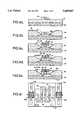
- FIGS. 1a-1care cross-sectional views, not to scale, that illustrate a method for fabricating a backside illuminated thermopile detector using a bonded silicon wafer, the detector being formed to include a radiation absorbing coating and a narrowband filter;
- FIGS. 2a-2care cross-sectional views, not to scale, that illustrate a method for fabricating a frontside illuminated thermopile detector using an isoplanar implanted (buried) oxide approach, while FIGS. 2d and 2e are planar views depicting the detector before (FIG. 2d) and after (FIG. 2e) the formation of the bi-metallic (Sb and Bi) thermocouples;
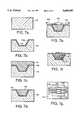
- FIGS. 3a-3gare cross-sectional views, not to scale, that illustrate a method for fabricating a frontside illuminated, thermally isolated thermopile detector using a buried oxide process, while FIG. 3h is a planar view illustrating the resultant detector;
- FIGS. 4a-4dare cross-sectional views, not to scale, illustrating a nitride bridge formation process without an underlying oxide (FIGS. 4a, 4b) and with an underlying support oxide (FIGS. 4c and 4d);
- FIG. 5ais a cross-sectional view, not to scale, detailing a first delineation and undercutting etch process, wherein the thermopile is protected by photoresist prior to etching
- FIG. 5bis a planar view showing the overlapping layers that comprise each individual thermocouple;
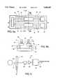
- FIGS. 6a-6eare cross-sectional views, not to scale, illustrating a frontside illuminated, silicon-on-sapphire (SOS) processing embodiment for forming a thermally isolated thermopile detector, while FIG. 6f is a planar view of the SOS thermopile detector showing associated lateral bipolar junction transistors (BJTs) forming a differential amplifier pair;
- SOSsilicon-on-sapphire
- FIGS. 7a-7fare cross-sectional views, not to scale, that illustrate a frontside illuminated, filled-polymer thermal detector/VLSI compatible process in accordance with an embodiment of the invention
- FIG. 7gis a planar view illustrating the interconnections of the thermopile arms to polymer bridges and silicon oxide;
- FIG. 8ais a top view of a frontside illuminated thermopile detector constructed in accordance with the method of FIGS. 2a-2c, while FIG. 8b is a cross-sectional view taken along the section line B--B of FIG. 8a;
- FIG. 9is a simplified block diagram showing the use of integrated thermopile detector of this invention in an application that senses the concentration of a molecular species of interest within a gas flow.
- FIGS. 1a-1dfor illustrating a first method of this invention for fabricating a backside illuminated thermopile detector using a bonded silicon wafer 10.
- a single thermal energy detectoris illustrated in these figures, it should be realized that a large number of identical thermal energy detectors can be simultaneously fabricated as a linear or as a two dimensional area array.
- FIG. 1aProcessing begins in FIG. 1a with a thinned silicon-on-insulator (SOI) wafer 10 comprised of a substrate 12, an electrically insulating (dielectric) layer (SiO 2 ) 14, and a thin silicon ⁇ 100> layer 16.
- the substrate 12has a thickness of approximately 100 micrometers to approximately 500 micrometers
- the SiO 2 dielectric layer 14a thickness of approximately 10,000 Angstroms
- the silicon film layer 16has a thickness within a range of approximately 2 micrometers to approximately 50 micrometers. Bonded silicon "wafers" having these characteristics are commercially available, or may be fabricated using known techniques.
- the Si layer 16is processed to form a recess 18.
- An etch using KOHis one suitable technique for forming the recess 18, in that the oxide layer 16 functions as an etch stop.
- thermopilea step of suitably masking and then depositing multiple (two or three) metal layers 20, 22 and 24 to form the thermal detector, in this case a thermopile.
- bilayer or trilayer thermopile formationinclude the use of Au, Bi, and Sb films (20, 22, and 24, respectively), wherein a temperature gradient is induced between the hot Bi/Sb (bilayer) or Bi/Au/Sb (trilayer) junctions (HJ 23) and the cold Bi/Sb (bilayer)--Bi/Au/Sb(trilayer) junction (CJ 25).
- the hot junction 23is formed over the region with no silicon (i.e., upon the low thermal conductivity bonding oxide 14) and the cold junctions 25 are formed on the surrounding silicon regions.
- Suitable thicknesses for the metal layersare 1000 ⁇ for the Bi, 2500 ⁇ for the Sb, and 0.5 microns for the Au.
- the ratio of the thickness of the Bi film to the Sb film(approximately 1:2.5) is maintained in all of the illustrated embodiments so as to equalize the thermal conductance over the entire metalized region.
- the Au layeris provided to efficiently couple the generated potential and may be replaced by any suitable high electrical conductivity material.
- thermopile formationi.e., materials which form bolometers (VOx), or superconducting transition edge bolometers (YBCO), or thin film pyroelectric detectors (e.g., BaSrTiO 3 ).
- FIG. 1dthere is performed a step of thermally isolating the hot junction (HJ 23) by backside etching of the silicon substrate 12 to the etch stop represented by the bonding oxide layer 14.
- the cavity 26may have a depth within a range of approximately 120 microns to approximately 200 microns, depending upon the thickness of the substrate 12.
- the depth of the cavity 26may also be selected to be a function of the wavelengths to be detected, thereby "tuning" the cavity to the desired range of wavelengths.
- a thin film "dark" radiation receiving or absorbing region 28is deposited upon the oxide 14 in registration with the backside of the hot junction 23.
- the absorbing region 28is preferably comprised of a multilayered Ti/ZnSe structure, although the use of these materials do not represent a limitation upon the practice of this invention.
- the region 28functions to convert incident electromagnetic radiation to thermal energy and to transfer the thermal energy, via the dielectric layer 14, to the hot junction (HJ 23) where the thermal energy is detected.
- a next stepdeposits or laminates an optical filter 30 that is registered to the thermopile detector element, the optical filter 30 defining the radiation receiving surface of the thermopile detector.
- Suitable filter fabrication techniquesinclude bonding a filter to the backside of the silicon substrate 12, and depositing a multilayered dielectric filter stack having a passband that is selected for the wavelengths of interest. Techniques for specifying and fabricating such multilayered filter stacks are known in the art. The filter passband characteristics are selected as a function of the wavelength or range of wavelengths of interest.
- the filter 30is deposited upon the substrate 12, it is preferable to first fill the cavity with a sacrificial material (for example a polyimide), deposit the filter 30, open an aperture within the filter 30, and then etch to remove the sacrificial material from the cavity 26.
- a sacrificial materialfor example a polyimide
- FIGS. 1a-1dboth shields from direct illumination any silicon electronics (for example, amplifier circuits) that may be formed in the silicon layer 16, and provides a high degree of optical isolation between individual thermopile detectors.
- silicon electronicsfor example, amplifier circuits
- FIGS. 2a-2eA second embodiment of this invention is illustrated in FIGS. 2a-2e, specifically a frontside illuminated, isoplanar-implanted SOI embodiment.
- FIG. 2aProcessing begins in FIG. 2a with a silicon structure 31 into which oxygen is implanted to form an SiO 2 buried layer 34.
- a suitable oxygen implant depth, from the top surface of the silicon structure 31,is approximately 0.5 micrometers.
- the buried layer 34thus differentiates the silicon structure into a lower substrate portion 32 and into an upper silicon portion or layer 36.
- An electrically insulating silicon nitride (Si 3 N 4 ) dielectric layer 38is deposited, masked, and then selectively removed to expose portions of the underlying silicon layer 36.
- an isoplanar oxide 40is grown into the exposed silicon through the use of a conventional technique.
- FIG. 2aillustrates the structure at the completion of the formation of the isoplanar oxide 40.
- the growth of the isoplanar oxide 40results in the formation of a silicon pedestal 39 having sloping sidewalls. A portion of the oxide grows laterally, that is, beneath the silicon nitride layer 38.
- an aperture or slot 42is etched through the silicon nitride layer 38 to expose the underlying silicon pedestal 39.
- the silicon pedestal 39is then etched away through the slot 42, resulting in the formation of a void 44 that is surrounded by the isoplanar oxide 40.
- This slotmay be conveniently self-aligned to the patterned thermopile detector. In this case, the thermopile detector is delineated prior to the photolithographic delineation/etching of the slot 42.
- the step illustrated in FIG. 2cis completed by the deposition of the Bi metalization 48, the Sb metalization 50, and the deposition of an electrically conductive strap or interconnect (Au 52) that electrically connects the Bi and Sb metalization 48 and 50, respectively, to form a hot junction 49 that is located upon the silicon nitride bridges and over the void 44.
- FIG. 2dis a planar view of the structure at the completion of the step of FIG. 2c.
- the Bi, Sb, and Au metalization 48, 50, and 52, respectivelyis deposited as shown to form the thermopile detector element.
- An external contact 54is also defined and formed and may be connected to another thermopile detector (not shown).
- the cold junctionsare formed on the silicon.
- the radiation absorbing layers 51 and bandpass filters 53are deposited and delineated on the hot junctions 49.
- the delineated filtersare confined to a small area slightly larger than the hot junction itself to minimize the addition of extra thermal capacitance and to maintain fast response.
- the delineated slotted silicon nitride bridges 46provide thermal isolation and rest on nitride dielectric 38 supports.
- the deposited and delineated thermopileis formed from the overlap of the Bi and Sb metalization lines 48 and 50. On this overlap region are deposited (delineated) both the radiation absorbing coating 51 and the dielectric filter 53.
- Contacts 54are provided to interface the thermopile detector to external circuitry and/or to interface same to other thermopile detectors.
- FIGS. 3a-3h and 4a-4dtwo buried oxide processes for forming manufacturable, high performance, low cost uncooled detectors are described below and illustrated in FIGS. 3a-3h and 4a-4d.
- These processesshare several unique advantages over conventional techniques for forming thermally isolated detectors, including the use of fewer mask steps, the utilization of a planar process, the formation of a low induced stress in the deposited film layers, and an excellent selectivity for etching the thermally isolating cavity.
- these processesare compatible with, and may be integrated into, a fully standard integrated circuit process line.
- Processingbegins in FIG. 3a by selecting a silicon substrate 60 that is suitable for the fabrication of silicon amplifier circuits.
- the substrate 60has a region 61 that is doped n + and which is eventually used as a common electrical contact.
- a region 62 of silicon nitrideis then deposited to define an extent of an active area or region which will eventually become a thermally isolating bridge structure.
- the bridge structurebeneficially reduces the thermal conduction of the structure and increases the thermopile sensitivity.
- a relatively thick (1 to 2 micrometers) layer 64 of laterally isolating isoplanar oxideis grown by, for example, a "wet" oxidation process.
- a resulting underlap of the isoplanar oxide 64 and the silicon nitride 62eventually supports the delineated silicon nitride bridges 64a that are shown in FIG. 3g.
- a small amount of oxidecan be grown on the silicon substrate 60 before the deposition of the silicon nitride region 62 and the patterning and growth of the isoplanar oxide layer 64.
- This thin layer of oxide(shown as layer 63 in FIGS. 4c and 4d) is employed to strengthen the silicon nitride bridges 64a.
- oxygenis implanted though the silicon nitride 62 and the isoplanar oxide 64 to form a buried oxide layer 66 that is separated from the silicon nitride structure 62 by an intervening thin region 67 of the silicon 60.
- a suitable implant depthis 0.5 micrometers.
- the implanted oxygenis then annealed to form the layer 66 as a continuous buried oxide layer that underlies the previously defined active region (that region that underlies the silicon nitride region 62).
- FIGS. 3e through 3gshow sequentially the deposition and delineation of the thermocouples which lay across the nitride region 62.
- FIG. 3eshows the deposition of strips of Sb (68) and Bi (70), followed by the application of a layer of photoresist 72.
- FIG. 3fillustrates the patterning of the silicon nitride region 62 by removal of those portions thereof that are not covered by metalization and photoresist. The selective removal of the silicon nitride region 62 may be beneficially self-aligned to the previously applied mask that defines the thermopile pattern of the nitride bridges (one bridge to each thermocouple).
- FIG. 3eshows the deposition of strips of Sb (68) and Bi (70), followed by the application of a layer of photoresist 72.
- FIG. 3fillustrates the patterning of the silicon nitride region 62 by removal of those portions thereof that are not covered by metalization and photoresist. The selective removal of the silicon
- the underlying thin region 67 of silicon that lies atop the buried oxide 66is removed by a selective etch, thereby forming a void 69 that undercuts the remaining silicon nitride of the region 62 and the adjacent isoplanar oxide layer 64.
- the silicon nitride bridges 62asupport and thermally isolate, in conjunction with void 69, the hot junctions of the thermopile detector.
- the silicon nitride 62 and the silicon oxide under-layer 63are both undercut, with the silicon oxide under-layer 63 providing additional strength for the isoplanar oxide bridges 64a.
- the Bi and Sb thermocouplesare employed with Au as a third layer to facilitate interconnection between the Bi and Sb, and also to any support circuits that are integrated on the silicon 60 or that are provided externally.
- processingcontinues as in FIG. 1d to etch the thermal cavity under the buried silicon oxide layer 66, deposit the absorbing layer, and provide a suitable backside filter.
- the planar view of the completed structure shown in FIG. 3hshows the formation of a serpentine arrangement of three pairs of hot junctions 71 (on the silicon nitride bridges 62a) and cold junctions 73 (on the oxide 64 on silicon 60) thermocouples.
- the equivalent third cold junctionis formed by the external connections to the separate gold leads 74 to the Bi and to the Sb, off of the nitride bridges 64a on which they lie.
- the less robust thermocouple materials(Sb and Bi) are protected by the photoresist 72, as is described below in reference to FIGS. 5a and 5b.
- thermopile materialswhich are preferably protected during the undercutting etch by being encased in the photoresist 72 (as is shown in the enlarged cross-sectional view of FIG. 5a).
- thermopile materialswhich are more robust, more compatible with standard silicon processes, or which have other advantages, such as higher Seebeck coefficients, may be used instead of the Sb and Bi materials described thus far.
- these other materialsinclude, but are not limited to, silicon (i.e.
- polysiliconbulk silicon or amorphous silicon; or other less conductive metals or semi-metals or semiconductors formed during traditional silicon processes.
- Examplesinclude: (1) Metal silicides or germanides (i.e., PtSi, PdSi, ErSi or the germanium analogs such as PdGe); (2) the conductive metal nitrides; or (3) higher Seebeck coefficient materials such as Te or BiTe.
- the hole or slot 65 within the photoresist layer 72 and the underlying silicon nitride 62is employed to enable the etch of the underlying silicon region 67 to form the void 69.
- the designator 61generally indicates the silicon cavity (void) boundary
- the designator 63generally indicates the progression of the undercut etch contours.
- the slot 65thus delineates the silicon nitride bridges 62a and also permits the initiation of the undercutting etch process.
- the hot junction 71is formed at the interface of the Sb 68, Bi 70, and Au 74 metalization.
- FIGS. 6a-6femploys a thin silicon epitaxial layer 80 that is grown on a sapphire wafer 82.
- This composite substrate structurecan be commercially obtained as a "Silicon-On-Sapphire" (SOS) wafer from a variety of sources.
- FIGS. 3a-3gProcessing is similar to that described above with respect to FIGS. 3a-3g, with the exception that the buried oxide layer is not implanted. That is, a silicon nitride region 84 is deposited to define the active area (FIG. 6a); and an isoplanar oxide layer 86 is grown into the silicon layer 80 so as to undercut the silicon nitride layer 84 (FIG. 6b) and form a silicon island or pedestal 80a.
- FIG. 6cshows the deposition of strips of Sb 88 and Bi 90, followed by the application of a layer of photoresist 92.
- FIG. 6dillustrates the patterning of the silicon nitride layer 84 by removal of those portions thereof that are not covered by metalization and photoresist.
- the selective removal of the silicon nitride 84may be self-aligned to the previously applied mask that defines the thermopile pattern of the nitride bridges (one bridge to each thermocouple).
- the silicon pedestal 80a that lies atop the sapphire substrate 82is removed by a selective etch, thereby forming a void 87 that undercuts the remaining silicon nitride layer 84 and isoplanar oxide 86.
- processingcontinues as in FIG. 1d to form the thermal cavity within the sapphire substrate 82, deposit the absorbing layer, and provide a suitable backside filter.
- This SOS embodimentis advantageous in that it readily enables the formation within the silicon layer 80 of CMOS and lateral bipolar circuits, and also high gain bipolar-MOS devices for amplification and processing of the thermal detector signals.
- FIG. 6fillustrates a differential bipolar transistor pair comprised of lateral bipolar junction transistors (BJTs) 94a and 94b that are fabricated by conventional semiconductor processing techniques within silicon islands 96a and 96b, respectively, that border the active region.
- BJTslateral bipolar junction transistors
- Each of the BJTs 94a and 94bincludes leads (for example aluminum) for contacting the collector (C) and emitter (E) terminals.
- a control or base (B) terminal of each BJTis coupled to one end of the serpentine thermopile structure comprised of the Sb 88, Bi 90, and Au 91 metalization, the three hot junctions of which are disposed upon the thermally isolating silicon nitride bridges 84a over the void 87 that is formed within the silicon layer 80.
- Transistor types other than BJTscan be employed in other embodiments of the invention.
- the SOS embodiment of FIG. 6is compatible with low resistance detectors such as thermopiles, thermocouples and bolometers. Furthermore, due to the relatively low silicon volume and good thermal conductivity of the sapphire substrate 82, the SOS-based sensor operates well at temperatures as high as 150° C. or more.
- any required support circuitrye.g., amplifiers, A/D converters, etc.
- the thermal energy detector of this inventionmay be integrated with its attendant support circuitry through the use of conventional integrated circuit processing techniques. This facilitates the impedance matching of the thermal detector to the support circuitry, and furthermore increases the signal-to-noise ratio by minimizing conductor lengths and eliminating multiple levels of interconnections between the thermal detector and the support circuitry.
- FIGS. 7a-7gA silicon-based, frontside illuminated thermal detector embodiment that utilizes a low thermal conductivity polymer for thermal isolation is shown in FIGS. 7a-7g.
- Processingbegins in FIG. 7a with a semiconductor (e.g., silicon) substrate 100.
- a hole or recess 100ais then etched into the substrate 100 (FIG. 7b).
- the recess 100amay have a depth of 100 micrometers, and a lateral extent that is also 100 micrometers.
- a thin layer of silicon oxideis grown over the surfaces of the substrate and recess 100a.
- the oxide covered recess 102is filled with a low thermal conductivity polymer 104, such as a spun-on polyimide, and in FIG.
- a low thermal conductivity polymer 104such as a spun-on polyimide
- the structure formed thus faris planarized with a suitable wet or dry etch.
- This stepleaves the oxide covered recess 100a filled with the polymer 104, and the oxide coating 102 exposed upon the top surface of the substrate 100.
- suitable masksare applied and Bi, Au, and Sb metalization (106, 108, 110, respectively) is selectively deposited over the oxide coating (forming cold junctions) and also over the polymer-filled recess (forming a hot junction).
- a maskis applied and trenches 112 are etched through the polymer 104, between the deposited metalization, so as to further reduce the thermal conductivity of the polymer 104.
- the trenches 112thus form polymer bridges 114.
- absorptive coatings and dielectric filter stacksare preferably formed over the hot junctions.
- FIG. 7gis a planar view of the structure showing a serpentine arrangement of Bi, Sb and Au metalization that forms a thermal detector having a plurality of hot junctions disposed on the polymer bridges 114 within the hole or recess formed within the oxide-covered silicon substrate 100. The hot junctions are thus thermally isolated from the silicon substrate 100.
- the perimeter of the hole or recess 100ais shown generally by the designator 116.
- vertical rather than lateral isolationis afforded by the combination of deep etching, filling of holes with the low thermal conductivity polymer, planarization, and the deposition and delineation of the thermal detector.
- thermopilesintegrated thermopiles
- spectral filters and absorbing coatingsare clearly superior to conventional thermal sensor implementations in manufacturability, yield, signal to noise ratio and minimum detectable signal.
- a NeDT of 50 mK or lessis achievable for an uncooled FPA that is constructed in accordance with this invention.
- the high degree of integrationi.e., thermal isolation, amplifiers, filters, and absorbing layers significantly reduces the cost of the thermal sensors, thereby making the use of such sensors practical for high volume automotive emissions chemically-specific sensor applications (both on-board and roadside), industrial pollution monitoring applications, spectroscopy applications, and imaging applications.
- a broadband optical source 122provides a beam (A) of electromagnetic radiation that is directed through a structure 124 that contains a flow (B) of material.
- the flow (B)may be a gas stream that is generated by the operation of a vehicle or a furnace.
- the gas streamcontains molecular species, such as hydrocarbons, CO, CO 2 , NO x and H 2 O, that may be a by-product of combustion.
- the system 120includes one or more of the novel thermal energy sensors 126 of this invention.
- Each thermal energy sensor 126which may be constructed in accordance with any of the above described embodiments, has a dielectric filter stack that has a passband selected as a function of a range of wavelengths that are known to be absorbed by a chemical species of interest.
- the output of the sensor 126is provided to suitable signal processing electronics, such as an amplifier 128 and a signal processor 130, some or all of which may be integrated within the same semiconductor substrate within which the thermal sensor(s) 126 is fabricated.
- the optical source 122provides the broadband beam (A) which passes through the gas stream (B).
- the presence of a chemical species of interest within the stream (B)results in the selective absorption of a portion of the band of wavelengths that comprise the beam (A).
- One of the thermal energy sensors 126is provided with a filter that passes electromagnetic radiation within the band that is absorbed by the chemical species of interest and, as a result, is responsive to an intensity of the beam (A) within the absorption band.
- the electromagnetic energy within the passbandis absorbed by the absorptive coating of the thermal sensor 126, is converted to thermal energy, and thus causes the thermal sensor (e.g., a thermopile sensor) to generate a detectable electrical signal that has a magnitude that is a function of the intensity of the beam (A) within the passband of the filter.
- This electrical signalis amplified and processed to provide, at an output 132 of the signal processor 130, a concentration of the chemical species within the flow (B).
- the entire system 120can be installed within a vehicle or a chimney.
- IR radiationwithin other wavelength bands can also be detected.
- visible and UV radiationcan be detected by providing a suitable layer of absorbing material within the optical cavity, and a suitable passband filter that is disposed over the optical cavity.
- Typical lateral dimensions for the active regions of each of the foregoing embodimentsare in the range of approximately 100 micrometers to approximately 1000 micrometers.
- an imaging arraysuch as an uncooled focal plane array, can be constructed to have a high density of radiation responsive sensors.
Landscapes
- Physics & Mathematics (AREA)
- General Physics & Mathematics (AREA)
- Spectroscopy & Molecular Physics (AREA)
- Photometry And Measurement Of Optical Pulse Characteristics (AREA)
Abstract
Description
Claims (33)
Priority Applications (1)
| Application Number | Priority Date | Filing Date | Title |
|---|---|---|---|
| US08/322,442US5689087A (en) | 1994-10-04 | 1994-10-04 | Integrated thermopile sensor for automotive, spectroscopic and imaging applications, and methods of fabricating same |
Applications Claiming Priority (1)
| Application Number | Priority Date | Filing Date | Title |
|---|---|---|---|
| US08/322,442US5689087A (en) | 1994-10-04 | 1994-10-04 | Integrated thermopile sensor for automotive, spectroscopic and imaging applications, and methods of fabricating same |
Publications (1)
| Publication Number | Publication Date |
|---|---|
| US5689087Atrue US5689087A (en) | 1997-11-18 |
Family
ID=23254910
Family Applications (1)
| Application Number | Title | Priority Date | Filing Date |
|---|---|---|---|
| US08/322,442Expired - LifetimeUS5689087A (en) | 1994-10-04 | 1994-10-04 | Integrated thermopile sensor for automotive, spectroscopic and imaging applications, and methods of fabricating same |
Country Status (1)
| Country | Link |
|---|---|
| US (1) | US5689087A (en) |
Cited By (38)
| Publication number | Priority date | Publication date | Assignee | Title |
|---|---|---|---|---|
| US6046398A (en)* | 1998-11-04 | 2000-04-04 | The United States Of America As Represented By The Administrator Of The National Aeronautics And Space Administration | Micromachined thermoelectric sensors and arrays and process for producing |
| US6081139A (en)* | 1997-09-25 | 2000-06-27 | Intel Corporation | Differential amplifier with lateral bipolar transistor |
| US6107645A (en)* | 1997-10-31 | 2000-08-22 | Fujitsu Limited | Thermoelectric system using semiconductor |
| US6117088A (en)* | 1998-10-06 | 2000-09-12 | Trex Medical Corporation | Panel connector for temperature gradient sensing probe |
| WO2000074150A1 (en)* | 1999-05-27 | 2000-12-07 | Robert Bosch Gmbh | Insulating device and method for producing an insulated region on a silicon substrate |
| WO2001009964A1 (en)* | 1999-07-30 | 2001-02-08 | Institute Of Microelectronics | Thin film thermopile arrangement |
| US6203194B1 (en)* | 1997-03-15 | 2001-03-20 | Braun Gmbh | Thermopile sensor for radiation thermometer or motion detector |
| US6238085B1 (en)* | 1998-12-31 | 2001-05-29 | Honeywell International Inc. | Differential thermal analysis sensor |
| US6305840B1 (en)* | 1998-02-28 | 2001-10-23 | Lg Electronics Inc. | Thermopile detector and method for fabricating the same |
| US20020060291A1 (en)* | 2000-11-22 | 2002-05-23 | Ihi Aerospace Co., Ltd | Infrared detecting device |
| US20030054179A1 (en)* | 2001-09-20 | 2003-03-20 | Nissan Motor Co., Ltd. | Radiation-absorbing layers for thermopile radiation detectors |
| US6548879B2 (en)* | 1999-11-01 | 2003-04-15 | Hiroyoshi Komobuchi | Semiconductor device having heat detecting element and insulating cavity and method of manufacturing the same |
| US20030147449A1 (en)* | 2002-02-04 | 2003-08-07 | Delphi Technologies, Inc. | Monolithically-integrated infrared sensor |
| US20030148620A1 (en)* | 2002-02-04 | 2003-08-07 | Chavan Abhijeet V. | Process for a monolithically-integrated micromachined sensor and circuit |
| US6637931B2 (en)* | 2001-07-19 | 2003-10-28 | Oriental System Technology Inc. | Probe for use in an infrared thermometer |
| US6661073B1 (en)* | 1999-03-26 | 2003-12-09 | Centre National De La Recherche Scientifique | Semiconductor infrared detector and method for the production thereof |
| US20040029309A1 (en)* | 2002-05-22 | 2004-02-12 | Thorsten Pannek | Method for manufacturing a component, in particular a thermal sensor, and thermal sensor |
| US20040148063A1 (en)* | 2001-03-07 | 2004-07-29 | 11138037 Ontari Ltd. ("Alirt") | Detecting device and method of using same |
| US6796641B2 (en)* | 1999-12-21 | 2004-09-28 | Eastman Kodak Company | Continuous ink jet printer with micro-valve deflection mechanism and method of making same |
| US6830987B1 (en)* | 2003-06-13 | 2004-12-14 | Advanced Micro Devices, Inc. | Semiconductor device with a silicon-on-void structure and method of making the same |
| US20050017175A1 (en)* | 2003-07-24 | 2005-01-27 | Delphi Technologies, Inc. | Infrared sensor package |
| US20060062439A1 (en)* | 2003-09-05 | 2006-03-23 | Authentec, Inc. | Integrated circuit infrared sensor and associated methods |
| US20070095380A1 (en)* | 2005-10-31 | 2007-05-03 | Dewes Brian E | Infrared detecting device with a circular membrane |
| WO2007071525A1 (en)* | 2005-12-21 | 2007-06-28 | Robert Bosch Gmbh | Micromechanical structure comprising a substrate and a thermoelement, temperature and/or radiation sensor, and method for producing a micromechnical structure |
| US7726876B2 (en) | 2007-03-14 | 2010-06-01 | Entegris, Inc. | System and method for non-intrusive thermal monitor |
| US20100265989A1 (en)* | 2006-12-05 | 2010-10-21 | Delphi Technologies, Inc. | P-n junction based thermal detector |
| US20100296546A1 (en)* | 2005-04-01 | 2010-11-25 | Trumpf Werkzeugmaschinen Gmbh + Co. Kg | Optical guide with temperature sensing matrix |
| WO2011126530A1 (en)* | 2010-03-30 | 2011-10-13 | Texas Instruments Incorporated | Semiconductor thermocouple and sensor |
| US20140036953A1 (en)* | 2010-04-26 | 2014-02-06 | Hme Co., Ltd. | Temperature sensor device and radiation thermometer using this device, production method of temperature sensor device, multi-layered thin film thermopile using photo-resist film and radiation thermometer using this thermopile, and production method of multi-layered thin film thermopile |
| US9741918B2 (en) | 2013-10-07 | 2017-08-22 | Hypres, Inc. | Method for increasing the integration level of superconducting electronics circuits, and a resulting circuit |
| US20180045580A1 (en)* | 2016-08-12 | 2018-02-15 | Qualcomm Incorporated | Thermopile mesh |
| US20180058936A1 (en)* | 2016-08-30 | 2018-03-01 | Pixart Imaging Inc. | Far infrared sensor apparatus having multiple sensing element arrays inside single package |
| CN107808877A (en)* | 2016-09-08 | 2018-03-16 | 原相科技股份有限公司 | Far infrared sensing array integrated circuit assembly and far infrared sensor package |
| WO2018203865A3 (en)* | 2017-01-12 | 2019-01-31 | Hat Teknoloji A.S. | A solar cell and a solar panel for generating electrical power from sunlight |
| US20210247240A1 (en)* | 2020-02-12 | 2021-08-12 | Tokyo Electron Limited | Multi-point thermocouples and assemblies for ceramic heating structures |
| WO2023164668A3 (en)* | 2022-02-24 | 2023-10-26 | University Of Notre Dame Du Lac | Infrared shack-hartmann wavefront sensor based on cavity-coupled nanoantennas |
| US11871668B2 (en)* | 2020-01-31 | 2024-01-09 | Stmicroelectronics S.R.L. | Thermoelectric generator |
| US12151442B1 (en) | 2020-06-09 | 2024-11-26 | Ingenarious Consultants LLC | Pliable material milling technology |
Citations (10)
| Publication number | Priority date | Publication date | Assignee | Title |
|---|---|---|---|---|
| US3293082A (en)* | 1959-09-22 | 1966-12-20 | Philips Corp | Thermo-electric device for measuring thermal radiation energy |
| US3436274A (en)* | 1965-05-25 | 1969-04-01 | Barnes Eng Co | Solid backed thermopile |
| US3758830A (en)* | 1972-04-10 | 1973-09-11 | Hewlett Packard Co | Transducer formed in peripherally supported thin semiconductor web |
| US3761318A (en)* | 1971-12-20 | 1973-09-25 | Barnes Eng Co | Edge detector utilizing all active junction radiation thermopiles |
| US4211888A (en)* | 1977-07-21 | 1980-07-08 | Siemens Aktiengesellschaft | Arrangement with several thermal elements in series connection |
| US4456919A (en)* | 1980-12-30 | 1984-06-26 | Horiba, Ltd. | Thermopile type detector with temperature sensor for cold junction |
| US4558342A (en)* | 1983-05-31 | 1985-12-10 | Rockwell International Corporation | Thermoelectric infrared detector array |
| US4571608A (en)* | 1983-01-03 | 1986-02-18 | Honeywell Inc. | Integrated voltage-isolation power supply |
| US5156688A (en)* | 1991-06-05 | 1992-10-20 | Xerox Corporation | Thermoelectric device |
| US5462608A (en)* | 1993-04-06 | 1995-10-31 | Imra Europe Sa | Peltier effect device to detect in particular a condensation risk on a surface being in contact with a wet air volume |
- 1994
- 1994-10-04USUS08/322,442patent/US5689087A/ennot_activeExpired - Lifetime
Patent Citations (10)
| Publication number | Priority date | Publication date | Assignee | Title |
|---|---|---|---|---|
| US3293082A (en)* | 1959-09-22 | 1966-12-20 | Philips Corp | Thermo-electric device for measuring thermal radiation energy |
| US3436274A (en)* | 1965-05-25 | 1969-04-01 | Barnes Eng Co | Solid backed thermopile |
| US3761318A (en)* | 1971-12-20 | 1973-09-25 | Barnes Eng Co | Edge detector utilizing all active junction radiation thermopiles |
| US3758830A (en)* | 1972-04-10 | 1973-09-11 | Hewlett Packard Co | Transducer formed in peripherally supported thin semiconductor web |
| US4211888A (en)* | 1977-07-21 | 1980-07-08 | Siemens Aktiengesellschaft | Arrangement with several thermal elements in series connection |
| US4456919A (en)* | 1980-12-30 | 1984-06-26 | Horiba, Ltd. | Thermopile type detector with temperature sensor for cold junction |
| US4571608A (en)* | 1983-01-03 | 1986-02-18 | Honeywell Inc. | Integrated voltage-isolation power supply |
| US4558342A (en)* | 1983-05-31 | 1985-12-10 | Rockwell International Corporation | Thermoelectric infrared detector array |
| US5156688A (en)* | 1991-06-05 | 1992-10-20 | Xerox Corporation | Thermoelectric device |
| US5462608A (en)* | 1993-04-06 | 1995-10-31 | Imra Europe Sa | Peltier effect device to detect in particular a condensation risk on a surface being in contact with a wet air volume |
Non-Patent Citations (8)
| Title |
|---|
| "A Batch-Fabricated Silicon Thermopile Unfrared Detector", G.R. Lahiji and Kensall D. Wise, IEEE Transactions On Electron Devices, vol. Ed-29, No. 1, Jan. 1982, pp. 14-22. |
| "A Linear Thermopile Infrared Detector Array With On-Chip Multiplexing", I.H. Choi and K.D. Wise, IEEE publication, 1985, pp. 132-135 No month available. |
| "A Silicon-Thermopile-Based Infrared Sensing Array For Use In Automated Manufacturing", I.H. Choi and K.D. Wise, IEEE Transactions On Electron Devices, vol. Ed-33, No. 1, Jan. 1986, pp. 72-79. |
| "The Role Of Thin Films In Integrated Solid-State Sensors", K.D. Wise, J. Vac. Sci Technol. A. vol. 4, No. 3, pp. 617-622, May/Jun. 1986. |
| A Batch Fabricated Silicon Thermopile Unfrared Detector , G.R. Lahiji and Kensall D. Wise, IEEE Transactions On Electron Devices, vol. Ed 29, No. 1, Jan. 1982, pp. 14 22.* |
| A Linear Thermopile Infrared Detector Array With On Chip Multiplexing , I.H. Choi and K.D. Wise, IEEE publication, 1985, pp. 132 135 No month available.* |
| A Silicon Thermopile Based Infrared Sensing Array For Use In Automated Manufacturing , I.H. Choi and K.D. Wise, IEEE Transactions On Electron Devices, vol. Ed 33, No. 1, Jan. 1986, pp. 72 79.* |
| The Role Of Thin Films In Integrated Solid State Sensors , K.D. Wise, J. Vac. Sci Technol. A. vol. 4, No. 3, pp. 617 622, May/Jun. 1986.* |
Cited By (66)
| Publication number | Priority date | Publication date | Assignee | Title |
|---|---|---|---|---|
| US6203194B1 (en)* | 1997-03-15 | 2001-03-20 | Braun Gmbh | Thermopile sensor for radiation thermometer or motion detector |
| US6081139A (en)* | 1997-09-25 | 2000-06-27 | Intel Corporation | Differential amplifier with lateral bipolar transistor |
| US6107645A (en)* | 1997-10-31 | 2000-08-22 | Fujitsu Limited | Thermoelectric system using semiconductor |
| US6305840B1 (en)* | 1998-02-28 | 2001-10-23 | Lg Electronics Inc. | Thermopile detector and method for fabricating the same |
| US6677654B2 (en) | 1998-02-28 | 2004-01-13 | Lg Electronics Inc. | Thermopile detector and method for fabricating the same |
| US6117088A (en)* | 1998-10-06 | 2000-09-12 | Trex Medical Corporation | Panel connector for temperature gradient sensing probe |
| US6123675A (en)* | 1998-10-06 | 2000-09-26 | Trex Medical Corporation | Temperature gradient sensing probe for monitoring hyperthermic medical treatments |
| US6046398A (en)* | 1998-11-04 | 2000-04-04 | The United States Of America As Represented By The Administrator Of The National Aeronautics And Space Administration | Micromachined thermoelectric sensors and arrays and process for producing |
| US6238085B1 (en)* | 1998-12-31 | 2001-05-29 | Honeywell International Inc. | Differential thermal analysis sensor |
| US6661073B1 (en)* | 1999-03-26 | 2003-12-09 | Centre National De La Recherche Scientifique | Semiconductor infrared detector and method for the production thereof |
| WO2000074150A1 (en)* | 1999-05-27 | 2000-12-07 | Robert Bosch Gmbh | Insulating device and method for producing an insulated region on a silicon substrate |
| WO2001009964A1 (en)* | 1999-07-30 | 2001-02-08 | Institute Of Microelectronics | Thin film thermopile arrangement |
| US6617659B2 (en) | 1999-11-01 | 2003-09-09 | Matsushita Electric Industrial Co., Ltd. | Semiconductor device having heat detecting element and insulating cavity and method of manufacturing thereof |
| US6548879B2 (en)* | 1999-11-01 | 2003-04-15 | Hiroyoshi Komobuchi | Semiconductor device having heat detecting element and insulating cavity and method of manufacturing the same |
| EP1146573A4 (en)* | 1999-11-01 | 2004-12-22 | Matsushita Electric Industrial Co Ltd | SEMICONDUCTOR DEVICE AND ITS MANUFACTURING METHOD |
| US6796641B2 (en)* | 1999-12-21 | 2004-09-28 | Eastman Kodak Company | Continuous ink jet printer with micro-valve deflection mechanism and method of making same |
| EP1209455A3 (en)* | 2000-11-22 | 2003-08-27 | IHI Aerospace Co., Ltd. | Infrared detecting device |
| US20020060291A1 (en)* | 2000-11-22 | 2002-05-23 | Ihi Aerospace Co., Ltd | Infrared detecting device |
| US6777680B2 (en) | 2000-11-22 | 2004-08-17 | Ihi Aerospace Co., Ltd. | Infrared detecting device |
| US20040148063A1 (en)* | 2001-03-07 | 2004-07-29 | 11138037 Ontari Ltd. ("Alirt") | Detecting device and method of using same |
| US7634341B2 (en)* | 2001-03-07 | 2009-12-15 | 1138037 Ontario Ltd. (“Alirt”) | Detecting device and method of using same |
| US6637931B2 (en)* | 2001-07-19 | 2003-10-28 | Oriental System Technology Inc. | Probe for use in an infrared thermometer |
| US20030054179A1 (en)* | 2001-09-20 | 2003-03-20 | Nissan Motor Co., Ltd. | Radiation-absorbing layers for thermopile radiation detectors |
| US6949286B2 (en) | 2001-09-20 | 2005-09-27 | Nissan Motor Co., Ltd. | Radiation-absorbing layers for thermopile radiation detectors |
| US6793389B2 (en) | 2002-02-04 | 2004-09-21 | Delphi Technologies, Inc. | Monolithically-integrated infrared sensor |
| US6828172B2 (en) | 2002-02-04 | 2004-12-07 | Delphi Technologies, Inc. | Process for a monolithically-integrated micromachined sensor and circuit |
| US20030147449A1 (en)* | 2002-02-04 | 2003-08-07 | Delphi Technologies, Inc. | Monolithically-integrated infrared sensor |
| US20030148620A1 (en)* | 2002-02-04 | 2003-08-07 | Chavan Abhijeet V. | Process for a monolithically-integrated micromachined sensor and circuit |
| US20050064619A1 (en)* | 2002-02-04 | 2005-03-24 | Delphi Technologies, Inc. | Process for a monolithically-integrated micromachined sensor and circuit |
| US20040029309A1 (en)* | 2002-05-22 | 2004-02-12 | Thorsten Pannek | Method for manufacturing a component, in particular a thermal sensor, and thermal sensor |
| US6933166B2 (en) | 2002-05-22 | 2005-08-23 | Robert Bosch Gmbh | Method for manufacturing a component, in particular a thermal sensor, and thermal sensor |
| US6830987B1 (en)* | 2003-06-13 | 2004-12-14 | Advanced Micro Devices, Inc. | Semiconductor device with a silicon-on-void structure and method of making the same |
| US7180064B2 (en)* | 2003-07-24 | 2007-02-20 | Delphi Technologies, Inc. | Infrared sensor package |
| US20050017175A1 (en)* | 2003-07-24 | 2005-01-27 | Delphi Technologies, Inc. | Infrared sensor package |
| US7351974B2 (en) | 2003-09-05 | 2008-04-01 | Authentec, Inc. | Integrated circuit infrared sensor and associated methods |
| US20060062439A1 (en)* | 2003-09-05 | 2006-03-23 | Authentec, Inc. | Integrated circuit infrared sensor and associated methods |
| US20100296546A1 (en)* | 2005-04-01 | 2010-11-25 | Trumpf Werkzeugmaschinen Gmbh + Co. Kg | Optical guide with temperature sensing matrix |
| US8591105B2 (en)* | 2005-04-01 | 2013-11-26 | Trumpf Werkzeugmaschinen Gmbh + Co. Kg | Optical guide with temperature sensing matrix |
| US20070095380A1 (en)* | 2005-10-31 | 2007-05-03 | Dewes Brian E | Infrared detecting device with a circular membrane |
| WO2007071525A1 (en)* | 2005-12-21 | 2007-06-28 | Robert Bosch Gmbh | Micromechanical structure comprising a substrate and a thermoelement, temperature and/or radiation sensor, and method for producing a micromechnical structure |
| JP2009520961A (en)* | 2005-12-21 | 2009-05-28 | ローベルト ボツシユ ゲゼルシヤフト ミツト ベシユレンクテル ハフツング | Micromachining structure with substrate and thermocouple, temperature sensor and / or radiation sensor and method for fabricating a micromachining structure |
| US20090168836A1 (en)* | 2005-12-21 | 2009-07-02 | Holger Hoefer | Micromechanical structure having a substrate and a thermoelement, temperature sensor and/or radiation sensor, and method for manufacturing a micromechanical structure |
| US20100265989A1 (en)* | 2006-12-05 | 2010-10-21 | Delphi Technologies, Inc. | P-n junction based thermal detector |
| US7726876B2 (en) | 2007-03-14 | 2010-06-01 | Entegris, Inc. | System and method for non-intrusive thermal monitor |
| WO2011126530A1 (en)* | 2010-03-30 | 2011-10-13 | Texas Instruments Incorporated | Semiconductor thermocouple and sensor |
| US8304851B2 (en) | 2010-03-30 | 2012-11-06 | Texas Instruments Incorporated | Semiconductor thermocouple and sensor |
| CN102823005A (en)* | 2010-03-30 | 2012-12-12 | 德克萨斯仪器股份有限公司 | Semiconductor thermocouple and sensor |
| US9759613B2 (en)* | 2010-04-26 | 2017-09-12 | Hme Co., Ltd. | Temperature sensor device and radiation thermometer using this device, production method of temperature sensor device, multi-layered thin film thermopile using photo-resist film and radiation thermometer using this thermopile, and production method of multi-layered thin film thermopile |
| US20140036953A1 (en)* | 2010-04-26 | 2014-02-06 | Hme Co., Ltd. | Temperature sensor device and radiation thermometer using this device, production method of temperature sensor device, multi-layered thin film thermopile using photo-resist film and radiation thermometer using this thermopile, and production method of multi-layered thin film thermopile |
| US9741918B2 (en) | 2013-10-07 | 2017-08-22 | Hypres, Inc. | Method for increasing the integration level of superconducting electronics circuits, and a resulting circuit |
| US10283694B2 (en) | 2013-10-07 | 2019-05-07 | Hypres, Inc. | Method for increasing the integration level of superconducting electronics circuits, and a resulting circuit |
| US20180045580A1 (en)* | 2016-08-12 | 2018-02-15 | Qualcomm Incorporated | Thermopile mesh |
| US10393594B2 (en)* | 2016-08-12 | 2019-08-27 | Qualcomm Incorporated | Thermopile mesh |
| US11054313B2 (en)* | 2016-08-30 | 2021-07-06 | Pixart Imaging Inc. | Far infrared sensor apparatus having multiple sensing element arrays inside single package |
| US20180058936A1 (en)* | 2016-08-30 | 2018-03-01 | Pixart Imaging Inc. | Far infrared sensor apparatus having multiple sensing element arrays inside single package |
| US11874174B2 (en) | 2016-08-30 | 2024-01-16 | Pixart Imaging Inc. | Far infrared sensor apparatus having multiple sensing element arrays inside single package |
| US11573127B2 (en) | 2016-08-30 | 2023-02-07 | Pixart Imaging Inc. | Far infrared sensor apparatus having multiple sensing element arrays inside single package |
| CN107808877A (en)* | 2016-09-08 | 2018-03-16 | 原相科技股份有限公司 | Far infrared sensing array integrated circuit assembly and far infrared sensor package |
| CN110729280A (en)* | 2016-09-08 | 2020-01-24 | 原相科技股份有限公司 | Far infrared sensing array integrated circuit assembly and far infrared sensor package |
| CN107808877B (en)* | 2016-09-08 | 2019-11-05 | 原相科技股份有限公司 | Far infrared sensing array integrated circuit assembly and far infrared sensor package |
| WO2018203865A3 (en)* | 2017-01-12 | 2019-01-31 | Hat Teknoloji A.S. | A solar cell and a solar panel for generating electrical power from sunlight |
| US11871668B2 (en)* | 2020-01-31 | 2024-01-09 | Stmicroelectronics S.R.L. | Thermoelectric generator |
| US20210247240A1 (en)* | 2020-02-12 | 2021-08-12 | Tokyo Electron Limited | Multi-point thermocouples and assemblies for ceramic heating structures |
| US11774298B2 (en)* | 2020-02-12 | 2023-10-03 | Tokyo Electron Limited | Multi-point thermocouples and assemblies for ceramic heating structures |
| US12151442B1 (en) | 2020-06-09 | 2024-11-26 | Ingenarious Consultants LLC | Pliable material milling technology |
| WO2023164668A3 (en)* | 2022-02-24 | 2023-10-26 | University Of Notre Dame Du Lac | Infrared shack-hartmann wavefront sensor based on cavity-coupled nanoantennas |
Similar Documents
| Publication | Publication Date | Title |
|---|---|---|
| US5689087A (en) | Integrated thermopile sensor for automotive, spectroscopic and imaging applications, and methods of fabricating same | |
| JP2834202B2 (en) | Infrared detector | |
| JP3386830B2 (en) | Bolometer, method for forming bolometer cell on semiconductor substrate, and infrared detection array comprising bolometer array | |
| US6573504B2 (en) | Infrared sensor and manufacturing method thereof | |
| EP0526551B1 (en) | Semiconductor film bolometer thermal infrared detector | |
| JP2744367B2 (en) | Multi-wavelength responsive infrared detector | |
| US6541298B2 (en) | Method of making infrared sensor with a thermoelectric converting portion | |
| CA2275863C (en) | Microbridge structure and a method for forming the microbridge structure | |
| US7786469B2 (en) | Thermal sensor with a silicon/germanium superlattice structure | |
| US7638769B2 (en) | Solid-state image sensing device, method for manufacturing the same, and imaging system | |
| US9417133B2 (en) | Infrared sensor structure and method | |
| EP3408630B1 (en) | An ir detector array device | |
| HK1007597B (en) | Semiconductor film bolometer thermal infrared detector | |
| US20120138800A1 (en) | On-chip calibration system and method for infrared sensor | |
| US10883804B2 (en) | Infra-red device | |
| JPH10185681A (en) | Thermal infrared sensor, method of manufacturing the same, and infrared image sensor using the same | |
| CN108885137A (en) | A kind of IR detector array equipment | |
| US5939971A (en) | Infrared bolometer | |
| JP2005043381A (en) | Thermal infrared detector and method for manufacturing the same | |
| WO2000034751A1 (en) | Infrared bolometer and method for manufacturing same | |
| JPH01136035A (en) | Manufacturing method of pyroelectric detection element | |
| JP2002340684A (en) | Manufacturing method of thermal infrared solid-state imaging device and thermal infrared solid-state imaging device | |
| JP2541458B2 (en) | Infrared sensor and manufacturing method thereof | |
| EP1137918B1 (en) | Infrared bolometer | |
| JPH0799346A (en) | Semiconductor infrared sensor and manufacturing method thereof |
Legal Events
| Date | Code | Title | Description |
|---|---|---|---|
| AS | Assignment | Owner name:SANTA BARBARA RESEARCH CENTER, CALIFORNIA Free format text:ASSIGNMENT OF ASSIGNORS INTEREST;ASSIGNOR:JACK, MICHAEL D.;REEL/FRAME:007113/0599 Effective date:19941003 | |
| STCF | Information on status: patent grant | Free format text:PATENTED CASE | |
| FPAY | Fee payment | Year of fee payment:4 | |
| FEPP | Fee payment procedure | Free format text:PAYOR NUMBER ASSIGNED (ORIGINAL EVENT CODE: ASPN); ENTITY STATUS OF PATENT OWNER: LARGE ENTITY | |
| FPAY | Fee payment | Year of fee payment:8 | |
| AS | Assignment | Owner name:HE HOLDINGS, INC., CALIFORNIA Free format text:MERGER;ASSIGNOR:HUGHES AIRCRAFT COMPANY;REEL/FRAME:016722/0088 Effective date:19971216 Owner name:HUGHES AIRCRAFT COMPANY, VIRGINIA Free format text:MERGER;ASSIGNOR:SANTA BARBARA RESEARCH CENTER;REEL/FRAME:016712/0877 Effective date:19961205 Owner name:RAYTHEON COMPANY, MASSACHUSETTS Free format text:MERGER;ASSIGNOR:HE HOLDINGS, INC.;REEL/FRAME:016722/0093 Effective date:19971217 | |
| FEPP | Fee payment procedure | Free format text:PAYOR NUMBER ASSIGNED (ORIGINAL EVENT CODE: ASPN); ENTITY STATUS OF PATENT OWNER: LARGE ENTITY Free format text:PAYER NUMBER DE-ASSIGNED (ORIGINAL EVENT CODE: RMPN); ENTITY STATUS OF PATENT OWNER: LARGE ENTITY | |
| FPAY | Fee payment | Year of fee payment:12 | |
| FEPP | Fee payment procedure | Free format text:PAYOR NUMBER ASSIGNED (ORIGINAL EVENT CODE: ASPN); ENTITY STATUS OF PATENT OWNER: LARGE ENTITY Free format text:PAYER NUMBER DE-ASSIGNED (ORIGINAL EVENT CODE: RMPN); ENTITY STATUS OF PATENT OWNER: LARGE ENTITY | |
| AS | Assignment | Owner name:OL SECURITY LIMITED LIABILITY COMPANY, DELAWARE Free format text:ASSIGNMENT OF ASSIGNORS INTEREST;ASSIGNOR:RAYTHEON COMPANY;REEL/FRAME:029117/0335 Effective date:20120730 |