US5688282A - Distraction apparatus for a knee - Google Patents
Distraction apparatus for a kneeDownload PDFInfo
- Publication number
- US5688282A US5688282AUS08/689,976US68997696AUS5688282AUS 5688282 AUS5688282 AUS 5688282AUS 68997696 AUS68997696 AUS 68997696AUS 5688282 AUS5688282 AUS 5688282A
- Authority
- US
- United States
- Prior art keywords
- runners
- pair
- distractor
- set forth
- extensions
- Prior art date
- Legal status (The legal status is an assumption and is not a legal conclusion. Google has not performed a legal analysis and makes no representation as to the accuracy of the status listed.)
- Expired - Lifetime
Links
Images


Classifications
- A—HUMAN NECESSITIES
- A61—MEDICAL OR VETERINARY SCIENCE; HYGIENE
- A61B—DIAGNOSIS; SURGERY; IDENTIFICATION
- A61B17/00—Surgical instruments, devices or methods
- A61B17/14—Surgical saws
- A61B17/15—Guides therefor
Definitions
- This inventionrelates to a distraction instrument used to balance the ligaments during a total knee replacement surgery.
- a conventional knee prosthesisusually comprises a tibial element implanted on a resection plane formed on the bone of the proximal upper part of the tibia, an intermediate meniscus, and a femoral component with two condyles requiring for its implantation in the distal lower part of the femur three resection planes.
- One planecorresponds to the extension position and the other two planes to the flexion position, as well as one, or perhaps two, chamfers each at approximately 45° planes on either side of the resection plane of the femur corresponding to the position of extension.
- the proximal upper part of the tibia and the distal lower part of the femurmust be resected, so that the same distance is preserved between the resection planes of these two bones, in both the extension position of the leg (corresponding to the standing position of the patient) and the flexion position of the leg (corresponding to the sitting position).
- the object of the present inventionis to provide an apparatus that will enable the surgeon to adjust the space between the proximal resection plane of the tibia and the distal resection plane of the femur in the extension position and to determine the second cutting (or resection) plane or planes of the femur in the flexion position, and if necessary, the cutting planes of the chamfers, while respecting the previously determined spacing.
- the space correction apparatus for knee prosthesiscomprises a body having parallel front and rear surfaces and two pairs of runners, arranged one above the other, all parallel to each other and extending, in a plane perpendicular to the front and rear surfaces, beyond the rear surface so as to form rear parts, and forward of the front surface of the body, so as to form front parts.
- the front and rear parts of the lower pair of runnersare integral with one another and can be moved simultaneously in relation to the body and the front and rear parts of the upper pair of runners are not integral.
- the front parts of the upper pair of runnerscan be moved individually in relation to the body, and the rear parts of the upper pair of runners are both integral with the body.
- the bodyis provided with a calibration arm attached to the body in such as way as to pivot around an axis perpendicular to the front and rear surfaces and preferably comprising a device for measuring the size of the femoral element and it can be provided with a detachable anterior-posterior (universally) cutting guide, which can be attached to the body in a specific position.
- a calibration armattached to the body in such as way as to pivot around an axis perpendicular to the front and rear surfaces and preferably comprising a device for measuring the size of the femoral element and it can be provided with a detachable anterior-posterior (universally) cutting guide, which can be attached to the body in a specific position.
- the apparatus according to the inventionis used in surgery as follows:
- the surgeonintroduces between the resection planes and the rear (extension) parts of the two pairs of runners or skids of the apparatus, which have previously been brought into contact with one another. He then separates the two pairs of runners from each other until their abutment on the resected planes, in order to obtain the spacing to be carried over to the flexion position.
- the surgeonthen balances the lateral ligament tension in this position where the rear part of the upper pair of runners is in contact with the resection site of the distal condyle of the femur and verifies the hip-knee-ankle alignment by means of a longitudinal rod threaded in the calibration arm.
- the alignment of the rod with the femorotibial anatomical axis of the patientruns from the center of the femoral head to the center of the ankle.
- the surgeonAfter removing the apparatus and attaching the anteroposterior cutting guide on the body, the surgeon introduces the front (flexion) parts of the two pairs of runners of the apparatus between the tibia and femur in position of flexion, then carries over the spacing obtained in the extension position, and can then, if necessary, individually move the front part of one or the other of the runners of the upper pair in order to cause the femur to turn and thus place the ligaments under tension, which stabilizes and recenters the patella.
- the cutting guidewhose position on the body and shape determines the anterior and posterior cutting planes of the femur in the flexion position, is then attached to the distal resected part of the femur by any appropriate means; the guide is disconnected from the apparatus and the surgeon can then create with a saw the anterior and posterior cutting planes of the femur, which in practice are orthogonal to the resected distal part of the femur as well as the one or two chamfers required for implantation of the femoral component of the prosthesis.
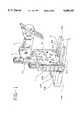
- FIG. 1represents a view in perspective of the apparatus of the present invention provided with a calibration arm having a device for measuring the size of the prosthetic femoral element;
- FIGS. 2, 3, 4 and 5represent, respectively, a side view, front view, top view and view in perspective of the body of the apparatus according to FIG. 1;
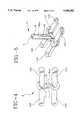
- FIGS. 6, 7, 8, 9 and 10represent, respectively, a front view, a section along line AA of FIG. 8, and a side view, top view and view in perspective of a movable portion of the apparatus according to FIG. 1;
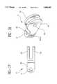
- FIGS. 11, 12, 13 and 14represent, respectively, a cut-away front view along line BB of FIG. 12, a side view, top view and view in perspective of the front part of one of the runners of the upper pair of runners;
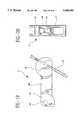
- FIGS. 15, 16, 17 and 18represent, respectively, a cut-away front view along line CC of FIG. 16, a side view, top view and view in perspective of a support for the calibration arm, with a device for measuring the size of the prosthetic femoral element of FIG. 1;
- FIGS. 19 to 22represent, respectively, a side view, front view, top view and a view in perspective of the calibration arm comprising a device for measuring the size of the femoral element of the knee prosthesis;
- FIGS. 23 and 24represent, respectively, a central maneuvering screw for the lower pair of runners and a lateral adjustment screw for only the front part of one of the runners of the upper pair of runners on the apparatus according to the invention
- FIGS. 25 to 28represent, respectively, a front view, side view, rear view and view in perspective of a retaining plate used with the apparatus of FIG. 1;
- FIGS. 29 to 31represent, respectively, views in perspective, seen lying down and upright, and a section along line EE of FIG. 29 of an anteroposterior cutting guide that can be attached to the apparatus according to the invention.
- the apparatuscomprises a body 1 having generally parallel front and rear surfaces and two pairs 2 and 3 of runners arranged one above the other, extending in a plane perpendicular to that of the front and rear body surfaces.
- runners of these two pairsare parallel to one another, each comprising a thicker rear part 21B, 22B and 31B, 32B located behind the plane of the rear surface of the body 1 and a thinner front part 21A, 22A and 31A, 32A located in front of the front surface of body 1 as shown in FIG. 1.
- runners or skids 21A, 21B, 22A and 22Bare integrally formed on a distraction plate 6.
- Body 1includes three parallel bores, the vertical axes of which lie in the same plane, which defines the front and rear surfaces of body 1.
- Each of these boresaccepts an adjustment screw 4A surmounted by a knurled knob, the central bore also accepting a support 4 for a calibration arm 5 provided with a device for measuring the size of the femoral element and mounted on a tubular extension 13.
- Moveable distraction plate 6is shown in FIGS. 2 to 5 which includes the lower pair 2 of runners 21, 22 which are made integral with a central pillar by means of a block 7.
- the block 7has two lateral faces 7A and 7B embedded in body 1.
- the central pillar 8has a circular cross section with two parallel flat faces, of which one, having the reference number 9, lies in the same plane as the front face 7C of the block 7 and the step 10 which is due to the difference in thickness between the front parts 21A and 22A and the rear parts 21B and 22B of the runners 21 and 22.
- Central pillar 8also comprises a threaded bore 11 located along the axis of the pillar, which runs from the upper part opposite the runners and opens into an oblong hole 12, crossing right through pillar 8 from one flat side to the other (see FIG. 2).
- pillar 8has a guide pin 8B, shown in FIGS. 2 to 5, designed to cooperate with a vertical groove 27B in body 1 to show the relative displacement of these elements and to serve as cursor moving along a graduation indicating the thicknesses of the meniscus of the knee prosthesis.
- FIGS. 6-10the body 1 of the preferred apparatus according to the invention will now be described.
- Body 1is generally rectangular in shape and has a central tubular extension 13 and with the rear parts 31B and 32B of the upper pair 3 of runners 31 and 32.
- body 1comprises three parallel cylindrical bores: the two side bores 14 and 15 are designed to receive the guide posts of the front parts of the runners of upper pair 3 and the central bore 16 is designed to receive the central pillar 8 of the spacer 6.
- the two side bores 14 and 15are open at their lower extremity and are extended at their upper extremity by a threaded bore of smaller diameter 17 and 18 serving for passage of an adjustment screw (not shown).
- Threaded bores 17 and 18are traversed at right angles by a lateral pin 19 and 20 respectively which emerges on the surfaces 211 and 222 of body 1.
- the central bore 16comprises in its lower part recessed surfaces 25A and B which cooperate with guide surfaces 7A and 7B of block 7 of spacer 6 at its median part, an oblong hole 26 corresponding to the oblong hole 12 of spacer 6, and is extended at its upper part by a central tubular extension 13.
- the central tubular extension 13comprises a notch 27 with pin 40B for receiving and immobilizing the support 4 of calibration arm 5 with a device for measuring the size of the femoral element, as respectively illustrated in FIG. 1.
- body 1has on its front surface position means for a retaining plate and a cutting guide, which can include, for example, threaded bores 36 and a window 37 delimited by vertical side walls 38 and 39.
- the front face of body 1is also provided with a vertical groove 27B illustrated in FIG. 10, cooperating with guide pin 8B of the pillar 8 as previously indicated.
- each front part 31A or 32A of the upper pair 3 of runners 31 and 32are each integral with posts 28.
- Posts 28is traversed by an axial threaded bore 30.
- the calibration arm support 4with a device for measuring the size of the femoral element, is illustrated in FIGS. 15 to 18; it consists of a base plate 40 comprising a pin 40B and a threaded bore 41 and is integral with two lugs 42, 43 pierced by a bore 44 whose axis is perpendicular to that of the bore 41.
- Bore 41is designed to receive the central adjustment screw 41B and bore 44 is designed to accommodate the axis of a bore 46 in a tongue portion 45 of calibration arm 5 which includes a device 51 for measuring the size of the femoral element.
- Support 4cooperates with notch 27 of the central tubular extension 13 when oriented in a direction parallel to the axis of the two pairs of runners of the apparatus and the two lugs 42, 43 which are in the form of a 90° sector, will receive between them the tail 45 of calibration arm 5 with the device described herein below.
- Arm 5equipped with a device for measuring the size of the femoral component, is illustrated in FIGS. 19 to 22.
- Arm 5comprises tongue 45 provided with bore 46 and integral with a sleeve 48 comprising at least one bore 50 and whose axis is perpendicular to that of bore 46.
- Tongue 45 of arm 5can be inserted between the lugs 42, 43 of the support 4 so as to align their respective bores 44 and 46 and to receive a rotation axis.
- arm 5can rotate approximately 90° around this axis, and a rigid rod of large size, about 1 meter to 1.5 meters, can be threaded through one of the bores 50 and be immobilized to visibly materialize a direction parallel to the femoro-tibial anatomical axis of the patient and make it possible for the surgeon to verify the hip-knee-ankle alignment, when the apparatus is inserted, through the rear parts of its runners, between the femur and the tibia of the patient with the leg in position of extension.
- Cylindrical element 49comprises, in order to measure the size of the prosthetic femoral element, a rigid pin 51 in the form of an inverted U, sliding in two parallel oblique grooves located on the opposite faces of the cylindrical element 49 and displaying reference marks all along a graduation appearing on one of these faces, as illustrated in FIG. 22.
- Central adjusting screw 41Billustrated in FIG. 23, comprises a head integral with a central knurled knob, and the body of the screw exhibits, starting from its head, two successive screw threads 50 and 51 of decreasing diameter separated by a groove 52.
- the thread of the end screw 51cooperates with the threaded bore 11 of the central pillar 8 of spacer 6 and groove 52 with pin 40B of the tubular extension 13, and the arm support 4 and the screw thread 50 is made integral with the central knurled knob.
- FIG. 24One of the two identical side screws 53, 54 is illustrated in FIG. 24. It comprises a head integral with a lateral knurled knob, and the body of the screw exhibits, starting from its head, two successive screw threads 55 and 56, of decreasing diameter, separated by a groove 57.
- Groove 57cooperates with the pin 19 or 20 of body 1, the screw thread 56 with the threaded bore 30 of the post 28, and the screw thread 55 is made integral with a knurled knob at the end of the screw.
- a retaining plate 61illustrated in FIGS. 25 to 28 and comprising an oblong hole 62 whose dimensions are analogous to those of oblong holes 12 and 26, perforations 63, 64 and perforated tenons 64B making it possible to position two spindles perpendicularly to the distal femoral cutting plane, is so dimensioned as to enable it to fit perfectly between the walls 38 and 39 of the window 37 of body 1 and to be screwed onto the latter at 36.
- the apparatus according to the inventioncan be equipped with an anteroposterior cutting guide 65 illustrated in FIGS. 29 to 31 for use with, for example, an oscillating saw blade.
- This anteroposterior cutting guide 65is presented in the shape of a trapezoidal cross section, the lower and upper surfaces of which are to serve as support for a surgical saw, to define the anterior and posterior cutting planes of the femur with the leg of the patient in flexion.
- Cutting guide 65is provided with positioned device cooperating with those of the body 1.
- these positioning devicescan consist of projections 66 cooperating with the perforations 64 of the retaining plate 61.
- the preferred cutting guide 65can also comprise one or several threaded bores 70, making it possible to fasten it with a suitable tool to body 1 in a recessed position.
- Guide 65also has several perpendicular holes 75 corresponding to those placed in the tenons 64B, making it possible to modify the position of the cutting template 65, and one, or preferably two, pairs of bores oriented at an angle of approximately 45° in converging directions from the face comprising the positioning means, as indicated by references 71, 72.
- itcan exhibit two planes 73 and 74 inclined at approximately 45° and designed to serve as guide for a surgical saw to execute the chamfers of the resection planes of the femur.
- the lower runners 21, 22are simultaneously mobile and the front parts 31A, 32A of the upper runners 31, 32 are individually mobile, according to a translational motion, in the direction of the axis of the adjusting screws 49, 53 and 54.
- the apparatusthus makes it possible for the surgeon to verify that the spacing of the resected parts between the femur and tibia is the same in position of extension as in position of flexion, and to make sure that the ligament tension is respected and that the centering of the patella is ensured before proceeding with the operations of distal resection of the femur in position of flexion.
Landscapes
- Health & Medical Sciences (AREA)
- Surgery (AREA)
- Life Sciences & Earth Sciences (AREA)
- Molecular Biology (AREA)
- General Health & Medical Sciences (AREA)
- Oral & Maxillofacial Surgery (AREA)
- Engineering & Computer Science (AREA)
- Biomedical Technology (AREA)
- Heart & Thoracic Surgery (AREA)
- Medical Informatics (AREA)
- Dentistry (AREA)
- Animal Behavior & Ethology (AREA)
- Nuclear Medicine, Radiotherapy & Molecular Imaging (AREA)
- Public Health (AREA)
- Veterinary Medicine (AREA)
- Prostheses (AREA)
- Surgical Instruments (AREA)
- Orthopedics, Nursing, And Contraception (AREA)
- Window Of Vehicle (AREA)
- Measurement Of Velocity Or Position Using Acoustic Or Ultrasonic Waves (AREA)
- Radar Systems Or Details Thereof (AREA)
- Ultra Sonic Daignosis Equipment (AREA)
Abstract
Description
Claims (16)
Applications Claiming Priority (2)
| Application Number | Priority Date | Filing Date | Title |
|---|---|---|---|
| FR9510055 | 1995-08-24 | ||
| FR9510055AFR2737967B1 (en) | 1995-08-24 | 1995-08-24 | KNEE PROSTHESIS CORRECTION APPARATUS |
Publications (1)
| Publication Number | Publication Date |
|---|---|
| US5688282Atrue US5688282A (en) | 1997-11-18 |
Family
ID=9482065
Family Applications (1)
| Application Number | Title | Priority Date | Filing Date |
|---|---|---|---|
| US08/689,976Expired - LifetimeUS5688282A (en) | 1995-08-24 | 1996-08-16 | Distraction apparatus for a knee |
Country Status (10)
| Country | Link |
|---|---|
| US (1) | US5688282A (en) |
| EP (1) | EP0761172B1 (en) |
| JP (1) | JP3255276B2 (en) |
| AT (1) | ATE218302T1 (en) |
| CZ (1) | CZ249896A3 (en) |
| DE (2) | DE69621532T2 (en) |
| FR (1) | FR2737967B1 (en) |
| HU (1) | HUP9602322A3 (en) |
| PL (1) | PL315736A1 (en) |
| ZA (1) | ZA967140B (en) |
Cited By (60)
| Publication number | Priority date | Publication date | Assignee | Title |
|---|---|---|---|---|
| FR2813780A1 (en)* | 2000-09-08 | 2002-03-15 | Biomet Merck France | Procedure and instrument for determining theoretical articulation interline of knee joint for prosthesis |
| US6488687B1 (en)* | 1997-09-18 | 2002-12-03 | Medidea, Llc | Joint replacement method and apparatus |
| US6575980B1 (en)* | 1997-01-28 | 2003-06-10 | New York Society For The Ruptured And Crippled Maintaining The Hospital For Special Surgery | Method and apparatus for femoral resection |
| US20040078042A1 (en)* | 1997-09-18 | 2004-04-22 | Masini Michael A. | Bone-conserving orthopedic instrumentation and appliances |
| US20050049603A1 (en)* | 2002-07-23 | 2005-03-03 | Ortho Development Corporation | Knee balancing block |
| US20050177169A1 (en)* | 2004-02-06 | 2005-08-11 | Synvasive Technology, Inc. | Dynamic knee balancer |
| US20070244488A1 (en)* | 2006-03-03 | 2007-10-18 | Robert Metzger | Tensor for use in surgical navigation |
| US20080243127A1 (en)* | 2001-05-25 | 2008-10-02 | Conformis, Inc. | Surgical Tools for Arthroplasty |
| US7559931B2 (en) | 2003-06-09 | 2009-07-14 | OrthAlign, Inc. | Surgical orientation system and method |
| US20090326544A1 (en)* | 2008-06-27 | 2009-12-31 | Ryan Chessar | Knee ligament balancer |
| US20100160919A1 (en)* | 2006-06-30 | 2010-06-24 | Howmedica Osteonics Corp. | Femoral component and instrumentation |
| US20100217338A1 (en)* | 2009-02-24 | 2010-08-26 | Wright Medical Technology, Inc. | Patient Specific Surgical Guide Locator and Mount |
| US7799084B2 (en) | 2002-10-23 | 2010-09-21 | Mako Surgical Corp. | Modular femoral component for a total knee joint replacement for minimally invasive implantation |
| US20110093081A1 (en)* | 2008-10-23 | 2011-04-21 | Synvasive Technology, Inc. | Knee balancing for revision procedures |
| US8057482B2 (en) | 2003-06-09 | 2011-11-15 | OrthAlign, Inc. | Surgical orientation device and method |
| US8066708B2 (en) | 2001-05-25 | 2011-11-29 | Conformis, Inc. | Patient selectable joint arthroplasty devices and surgical tools |
| US8118815B2 (en) | 2009-07-24 | 2012-02-21 | OrthAlign, Inc. | Systems and methods for joint replacement |
| US8122582B2 (en) | 2001-05-25 | 2012-02-28 | Conformis, Inc. | Surgical tools facilitating increased accuracy, speed and simplicity in performing joint arthroplasty |
| US8343218B2 (en) | 2001-05-25 | 2013-01-01 | Conformis, Inc. | Methods and compositions for articular repair |
| US8377129B2 (en) | 2001-05-25 | 2013-02-19 | Conformis, Inc. | Joint arthroplasty devices and surgical tools |
| US8439926B2 (en) | 2001-05-25 | 2013-05-14 | Conformis, Inc. | Patient selectable joint arthroplasty devices and surgical tools |
| US8500740B2 (en) | 2006-02-06 | 2013-08-06 | Conformis, Inc. | Patient-specific joint arthroplasty devices for ligament repair |
| US8551023B2 (en) | 2009-03-31 | 2013-10-08 | Depuy (Ireland) | Device and method for determining force of a knee joint |
| US8556830B2 (en) | 2009-03-31 | 2013-10-15 | Depuy | Device and method for displaying joint force data |
| US8597210B2 (en) | 2009-03-31 | 2013-12-03 | Depuy (Ireland) | System and method for displaying joint force data |
| USD696782S1 (en) | 2013-03-08 | 2013-12-31 | Stryker Corporation | Joint stabilizing instrument |
| US8623026B2 (en) | 2006-02-06 | 2014-01-07 | Conformis, Inc. | Patient selectable joint arthroplasty devices and surgical tools incorporating anatomical relief |
| US8721568B2 (en) | 2009-03-31 | 2014-05-13 | Depuy (Ireland) | Method for performing an orthopaedic surgical procedure |
| US8740817B2 (en) | 2009-03-31 | 2014-06-03 | Depuy (Ireland) | Device and method for determining forces of a patient's joint |
| US8758355B2 (en) | 2004-02-06 | 2014-06-24 | Synvasive Technology, Inc. | Dynamic knee balancer with pressure sensing |
| US8808303B2 (en) | 2009-02-24 | 2014-08-19 | Microport Orthopedics Holdings Inc. | Orthopedic surgical guide |
| US8911447B2 (en) | 2008-07-24 | 2014-12-16 | OrthAlign, Inc. | Systems and methods for joint replacement |
| US8951260B2 (en) | 2001-05-25 | 2015-02-10 | Conformis, Inc. | Surgical cutting guide |
| US8974459B1 (en) | 2010-05-21 | 2015-03-10 | Howmedica Osteonics Corp. | Natural alignment knee instruments |
| US8974468B2 (en) | 2008-09-10 | 2015-03-10 | OrthAlign, Inc. | Hip surgery systems and methods |
| US9192459B2 (en) | 2000-01-14 | 2015-11-24 | Bonutti Skeletal Innovations Llc | Method of performing total knee arthroplasty |
| US9339226B2 (en) | 2010-01-21 | 2016-05-17 | OrthAlign, Inc. | Systems and methods for joint replacement |
| US9381011B2 (en) | 2012-03-29 | 2016-07-05 | Depuy (Ireland) | Orthopedic surgical instrument for knee surgery |
| US9486226B2 (en) | 2012-04-18 | 2016-11-08 | Conformis, Inc. | Tibial guides, tools, and techniques for resecting the tibial plateau |
| US9545459B2 (en) | 2012-03-31 | 2017-01-17 | Depuy Ireland Unlimited Company | Container for surgical instruments and system including same |
| US9549742B2 (en) | 2012-05-18 | 2017-01-24 | OrthAlign, Inc. | Devices and methods for knee arthroplasty |
| US9649160B2 (en) | 2012-08-14 | 2017-05-16 | OrthAlign, Inc. | Hip replacement navigation system and method |
| US9649117B2 (en) | 2009-02-24 | 2017-05-16 | Microport Orthopedics Holdings, Inc. | Orthopedic surgical guide |
| US9675471B2 (en) | 2012-06-11 | 2017-06-13 | Conformis, Inc. | Devices, techniques and methods for assessing joint spacing, balancing soft tissues and obtaining desired kinematics for joint implant components |
| US9717512B2 (en) | 2012-11-26 | 2017-08-01 | Howmedica Osteonics Corp. | Programmable femoral pin guide |
| US10070973B2 (en) | 2012-03-31 | 2018-09-11 | Depuy Ireland Unlimited Company | Orthopaedic sensor module and system for determining joint forces of a patient's knee joint |
| US10098761B2 (en) | 2012-03-31 | 2018-10-16 | DePuy Synthes Products, Inc. | System and method for validating an orthopaedic surgical plan |
| US10105242B2 (en) | 2011-09-07 | 2018-10-23 | Depuy Ireland Unlimited Company | Surgical instrument and method |
| US10206792B2 (en) | 2012-03-31 | 2019-02-19 | Depuy Ireland Unlimited Company | Orthopaedic surgical system for determining joint forces of a patients knee joint |
| US10363149B2 (en) | 2015-02-20 | 2019-07-30 | OrthAlign, Inc. | Hip replacement navigation system and method |
| US10405994B2 (en) | 2015-09-18 | 2019-09-10 | Howmedica Osteonics Corp. | Femoral sizer |
| US10863995B2 (en) | 2017-03-14 | 2020-12-15 | OrthAlign, Inc. | Soft tissue measurement and balancing systems and methods |
| US10869771B2 (en) | 2009-07-24 | 2020-12-22 | OrthAlign, Inc. | Systems and methods for joint replacement |
| US10918499B2 (en) | 2017-03-14 | 2021-02-16 | OrthAlign, Inc. | Hip replacement navigation systems and methods |
| US11357644B2 (en) | 2011-10-24 | 2022-06-14 | Synvasive Technology, Inc. | Knee balancing devices, systems and methods |
| US11583262B2 (en) | 2018-12-18 | 2023-02-21 | DeHeer Orthopedics LLC | Retractor |
| US12108959B2 (en) | 2019-05-29 | 2024-10-08 | Wright Medical Technology, Inc. | Preparing a tibia for receiving tibial implant component of a replacement ankle |
| US12383287B2 (en) | 2009-02-24 | 2025-08-12 | Microport Orthopedics Holdings, Inc. | Systems and methods for installing an orthopedic implant |
| US12396739B2 (en) | 2020-01-17 | 2025-08-26 | Wright Medical Technology, Inc. | Guidance tools, systems, and methods |
| US12440227B2 (en) | 2022-01-05 | 2025-10-14 | Wright Medical Technology, Inc. | Preparing a tibia for receiving tibial implant component of a replacement ankle |
Families Citing this family (2)
| Publication number | Priority date | Publication date | Assignee | Title |
|---|---|---|---|---|
| AU2589699A (en) | 1998-02-06 | 1999-08-23 | Ronald J. Brinkerhoff | Device for visualizing, dissecting and harvesting vessels |
| DE20014377U1 (en)* | 2000-08-19 | 2002-01-10 | Stratec Medical Ag, Oberdorf | Device for optimizing a knee endoprosthesis |
Citations (8)
| Publication number | Priority date | Publication date | Assignee | Title |
|---|---|---|---|---|
| US4501266A (en)* | 1983-03-04 | 1985-02-26 | Biomet, Inc. | Knee distraction device |
| US4566448A (en)* | 1983-03-07 | 1986-01-28 | Rohr Jr William L | Ligament tensor and distal femoral resector guide |
| US4653488A (en)* | 1982-02-18 | 1987-03-31 | Howmedica, Inc. | Prosthetic knee implantation |
| FR2648699A1 (en)* | 1989-06-26 | 1990-12-28 | Matco | Multi-purpose aiming device for a sliding total knee prosthesis |
| US5116338A (en)* | 1988-02-03 | 1992-05-26 | Pfizer Hospital Products Group, Inc. | Apparatus for knee prosthesis |
| US5213112A (en)* | 1992-01-29 | 1993-05-25 | Pfizer Hospital Products Group, Inc. | Tension meter for orthopedic surgery |
| DE9301611U1 (en)* | 1992-02-07 | 1993-06-03 | Howmedica International Inc., Shannon, Clare | Orthopaedic instrument |
| US5468244A (en)* | 1991-11-06 | 1995-11-21 | Howmedica International, Inc. | Surgical apparatus for use in joint replacement surgery |
- 1995
- 1995-08-24FRFR9510055Apatent/FR2737967B1/ennot_activeExpired - Fee Related
- 1996
- 1996-08-16PLPL96315736Apatent/PL315736A1/enunknown
- 1996-08-16USUS08/689,976patent/US5688282A/ennot_activeExpired - Lifetime
- 1996-08-21DEDE69621532Tpatent/DE69621532T2/ennot_activeExpired - Lifetime
- 1996-08-21EPEP96401802Apatent/EP0761172B1/ennot_activeExpired - Lifetime
- 1996-08-21ATAT96401802Tpatent/ATE218302T1/ennot_activeIP Right Cessation
- 1996-08-21DEDE29614482Upatent/DE29614482U1/ennot_activeExpired - Lifetime
- 1996-08-22ZAZA9607140Apatent/ZA967140B/enunknown
- 1996-08-23HUHU9602322Apatent/HUP9602322A3/enunknown
- 1996-08-23JPJP22249696Apatent/JP3255276B2/ennot_activeExpired - Lifetime
- 1996-08-23CZCZ962498Apatent/CZ249896A3/enunknown
Patent Citations (8)
| Publication number | Priority date | Publication date | Assignee | Title |
|---|---|---|---|---|
| US4653488A (en)* | 1982-02-18 | 1987-03-31 | Howmedica, Inc. | Prosthetic knee implantation |
| US4501266A (en)* | 1983-03-04 | 1985-02-26 | Biomet, Inc. | Knee distraction device |
| US4566448A (en)* | 1983-03-07 | 1986-01-28 | Rohr Jr William L | Ligament tensor and distal femoral resector guide |
| US5116338A (en)* | 1988-02-03 | 1992-05-26 | Pfizer Hospital Products Group, Inc. | Apparatus for knee prosthesis |
| FR2648699A1 (en)* | 1989-06-26 | 1990-12-28 | Matco | Multi-purpose aiming device for a sliding total knee prosthesis |
| US5468244A (en)* | 1991-11-06 | 1995-11-21 | Howmedica International, Inc. | Surgical apparatus for use in joint replacement surgery |
| US5213112A (en)* | 1992-01-29 | 1993-05-25 | Pfizer Hospital Products Group, Inc. | Tension meter for orthopedic surgery |
| DE9301611U1 (en)* | 1992-02-07 | 1993-06-03 | Howmedica International Inc., Shannon, Clare | Orthopaedic instrument |
Non-Patent Citations (2)
| Title |
|---|
| "Total Knee-Replacement Arthroplasty", Journal of Bone & Joint Surgery, vol. 65a., No. 3, Mar. 1983, pp. 293-309, by N.S. Effekhar. |
| Total Knee Replacement Arthroplasty , Journal of Bone & Joint Surgery, vol. 65a., No. 3, Mar. 1983, pp. 293 309, by N.S. Effekhar.* |
Cited By (205)
| Publication number | Priority date | Publication date | Assignee | Title |
|---|---|---|---|---|
| US6575980B1 (en)* | 1997-01-28 | 2003-06-10 | New York Society For The Ruptured And Crippled Maintaining The Hospital For Special Surgery | Method and apparatus for femoral resection |
| US7128745B2 (en) | 1997-09-18 | 2006-10-31 | Medidea, Llc | Joint replacement methods and apparatus |
| US6488687B1 (en)* | 1997-09-18 | 2002-12-03 | Medidea, Llc | Joint replacement method and apparatus |
| US20030093079A1 (en)* | 1997-09-18 | 2003-05-15 | Masini Michael A. | Joint replacement methods and apparatus |
| US20040078043A1 (en)* | 1997-09-18 | 2004-04-22 | Masini Michael A. | Joint replacement methods and apparatus |
| US20040078042A1 (en)* | 1997-09-18 | 2004-04-22 | Masini Michael A. | Bone-conserving orthopedic instrumentation and appliances |
| US7419491B2 (en) | 1997-09-18 | 2008-09-02 | Medidea, Llc | Bone-conserving orthopedic instrumentation and appliances |
| US9192459B2 (en) | 2000-01-14 | 2015-11-24 | Bonutti Skeletal Innovations Llc | Method of performing total knee arthroplasty |
| FR2813780A1 (en)* | 2000-09-08 | 2002-03-15 | Biomet Merck France | Procedure and instrument for determining theoretical articulation interline of knee joint for prosthesis |
| US9216025B2 (en) | 2001-05-25 | 2015-12-22 | Conformis, Inc. | Joint arthroplasty devices and surgical tools |
| US8460304B2 (en) | 2001-05-25 | 2013-06-11 | Conformis, Inc. | Joint arthroplasty devices and surgical tools |
| US8768028B2 (en) | 2001-05-25 | 2014-07-01 | Conformis, Inc. | Methods and compositions for articular repair |
| US8951259B2 (en) | 2001-05-25 | 2015-02-10 | Conformis, Inc. | Patient selectable joint arthroplasty devices and surgical tools |
| US20080243127A1 (en)* | 2001-05-25 | 2008-10-02 | Conformis, Inc. | Surgical Tools for Arthroplasty |
| US9579110B2 (en) | 2001-05-25 | 2017-02-28 | Conformis, Inc. | Patient selectable joint arthroplasty devices and surgical tools |
| US8951260B2 (en) | 2001-05-25 | 2015-02-10 | Conformis, Inc. | Surgical cutting guide |
| US8998915B2 (en) | 2001-05-25 | 2015-04-07 | Conformis, Inc. | Joint arthroplasty devices and surgical tools |
| US9023050B2 (en) | 2001-05-25 | 2015-05-05 | Conformis, Inc. | Surgical tools for arthroplasty |
| US8657827B2 (en) | 2001-05-25 | 2014-02-25 | Conformis, Inc. | Surgical tools for arthroplasty |
| US8641716B2 (en) | 2001-05-25 | 2014-02-04 | Conformis, Inc. | Joint arthroplasty devices and surgical tools |
| US9358018B2 (en) | 2001-05-25 | 2016-06-07 | Conformis, Inc. | Joint arthroplasty devices and surgical tools |
| US9055953B2 (en) | 2001-05-25 | 2015-06-16 | Conformis, Inc. | Methods and compositions for articular repair |
| US8617172B2 (en) | 2001-05-25 | 2013-12-31 | Conformis, Inc. | Joint arthroplasty devices and surgical tools |
| US9066728B2 (en) | 2001-05-25 | 2015-06-30 | Conformis, Inc. | Surgical tools facilitating increased accuracy, speed and simplicity in performing joint arthroplasty |
| US9072531B2 (en) | 2001-05-25 | 2015-07-07 | Conformis, Inc. | Patient selectable joint arthroplasty devices and surgical tools |
| US9295482B2 (en) | 2001-05-25 | 2016-03-29 | Conformis, Inc. | Patient selectable joint arthroplasty devices and surgical tools |
| US7981158B2 (en) | 2001-05-25 | 2011-07-19 | Conformis, Inc. | Patient selectable joint arthroplasty devices and surgical tools |
| US8585708B2 (en) | 2001-05-25 | 2013-11-19 | Conformis, Inc. | Patient selectable joint arthroplasty devices and surgical tools |
| US9084617B2 (en) | 2001-05-25 | 2015-07-21 | Conformis, Inc. | Patient selectable joint arthroplasty devices and surgical tools |
| US8062302B2 (en)* | 2001-05-25 | 2011-11-22 | Conformis, Inc. | Surgical tools for arthroplasty |
| US8066708B2 (en) | 2001-05-25 | 2011-11-29 | Conformis, Inc. | Patient selectable joint arthroplasty devices and surgical tools |
| US8083745B2 (en) | 2001-05-25 | 2011-12-27 | Conformis, Inc. | Surgical tools for arthroplasty |
| US8105330B2 (en) | 2001-05-25 | 2012-01-31 | Conformis, Inc. | Patient selectable joint arthroplasty devices and surgical tools |
| US8562611B2 (en) | 2001-05-25 | 2013-10-22 | Conformis, Inc. | Joint arthroplasty devices and surgical tools |
| US8122582B2 (en) | 2001-05-25 | 2012-02-28 | Conformis, Inc. | Surgical tools facilitating increased accuracy, speed and simplicity in performing joint arthroplasty |
| US8568480B2 (en) | 2001-05-25 | 2013-10-29 | Conformis, Inc. | Joint arthroplasty devices and surgical tools |
| US9186161B2 (en) | 2001-05-25 | 2015-11-17 | Conformis, Inc. | Surgical tools for arthroplasty |
| US8337501B2 (en) | 2001-05-25 | 2012-12-25 | Conformis, Inc. | Patient selectable joint arthroplasty devices and surgical tools |
| US8343218B2 (en) | 2001-05-25 | 2013-01-01 | Conformis, Inc. | Methods and compositions for articular repair |
| US8366771B2 (en) | 2001-05-25 | 2013-02-05 | Conformis, Inc. | Surgical tools facilitating increased accuracy, speed and simplicity in performing joint arthroplasty |
| US8377129B2 (en) | 2001-05-25 | 2013-02-19 | Conformis, Inc. | Joint arthroplasty devices and surgical tools |
| US8439926B2 (en) | 2001-05-25 | 2013-05-14 | Conformis, Inc. | Patient selectable joint arthroplasty devices and surgical tools |
| US8568479B2 (en) | 2001-05-25 | 2013-10-29 | Conformis, Inc. | Joint arthroplasty devices and surgical tools |
| US9125672B2 (en) | 2001-05-25 | 2015-09-08 | Conformis, Inc. | Joint arthroplasty devices and surgical tools |
| US9107679B2 (en) | 2001-05-25 | 2015-08-18 | Conformis, Inc. | Patient selectable joint arthroplasty devices and surgical tools |
| US9125673B2 (en) | 2001-05-25 | 2015-09-08 | Conformis, Inc. | Joint arthroplasty devices and surgical tools |
| US8529630B2 (en) | 2001-05-25 | 2013-09-10 | Conformis, Inc. | Patient selectable joint arthroplasty devices and surgical tools |
| US8551169B2 (en) | 2001-05-25 | 2013-10-08 | Conformis, Inc. | Joint arthroplasty devices and surgical tools |
| US8551102B2 (en) | 2001-05-25 | 2013-10-08 | Conformis, Inc. | Joint arthroplasty devices and surgical tools |
| US8551099B2 (en) | 2001-05-25 | 2013-10-08 | Conformis, Inc. | Surgical tools for arthroplasty |
| US8551103B2 (en) | 2001-05-25 | 2013-10-08 | Conformis, Inc. | Joint arthroplasty devices and surgical tools |
| US8561278B2 (en) | 2001-05-25 | 2013-10-22 | Conformis, Inc. | Joint arthroplasty devices and surgical tools |
| US8556906B2 (en) | 2001-05-25 | 2013-10-15 | Conformis, Inc. | Joint arthroplasty devices and surgical tools |
| US9107680B2 (en) | 2001-05-25 | 2015-08-18 | Conformis, Inc. | Patient selectable joint arthroplasty devices and surgical tools |
| US8556907B2 (en) | 2001-05-25 | 2013-10-15 | Conformis, Inc. | Joint arthroplasty devices and surgical tools |
| US8562618B2 (en) | 2001-05-25 | 2013-10-22 | Conformis, Inc. | Joint arthroplasty devices and surgical tools |
| US7628793B2 (en) | 2002-07-23 | 2009-12-08 | Ortho Development Corporation | Knee balancing block |
| US20050049603A1 (en)* | 2002-07-23 | 2005-03-03 | Ortho Development Corporation | Knee balancing block |
| US7799084B2 (en) | 2002-10-23 | 2010-09-21 | Mako Surgical Corp. | Modular femoral component for a total knee joint replacement for minimally invasive implantation |
| US8888786B2 (en) | 2003-06-09 | 2014-11-18 | OrthAlign, Inc. | Surgical orientation device and method |
| US11903597B2 (en) | 2003-06-09 | 2024-02-20 | OrthAlign, Inc. | Surgical orientation system and method |
| US11179167B2 (en) | 2003-06-09 | 2021-11-23 | OrthAlign, Inc. | Surgical orientation system and method |
| US8057482B2 (en) | 2003-06-09 | 2011-11-15 | OrthAlign, Inc. | Surgical orientation device and method |
| US8057479B2 (en) | 2003-06-09 | 2011-11-15 | OrthAlign, Inc. | Surgical orientation system and method |
| US7559931B2 (en) | 2003-06-09 | 2009-07-14 | OrthAlign, Inc. | Surgical orientation system and method |
| US8974467B2 (en) | 2003-06-09 | 2015-03-10 | OrthAlign, Inc. | Surgical orientation system and method |
| US9314256B2 (en) | 2003-11-25 | 2016-04-19 | Conformis, Inc. | Patient selectable joint arthroplasty devices and surgical tools |
| US9375222B2 (en) | 2003-11-25 | 2016-06-28 | Conformis, Inc. | Patient selectable joint arthroplasty devices and surgical tools |
| US9113921B2 (en) | 2003-11-25 | 2015-08-25 | Conformis, Inc. | Patient selectable joint arthroplasty devices and surgical tools |
| US9381025B2 (en) | 2003-11-25 | 2016-07-05 | Conformis, Inc. | Patient selectable joint arthroplasty devices and surgical tools |
| US9408615B2 (en) | 2003-11-25 | 2016-08-09 | Conformis, Inc. | Patient selectable joint arthroplasty devices and surgical tools |
| US9241725B2 (en) | 2003-11-25 | 2016-01-26 | Conformis, Inc. | Patient selectable joint arthroplasty devices and surgical tools |
| US9295481B2 (en) | 2003-11-25 | 2016-03-29 | Conformis, Inc. | Patient selectable joint arthroplasty devices and surgical tools |
| US9308005B2 (en) | 2003-11-25 | 2016-04-12 | Conformis, Inc. | Patient selectable joint arthroplasty devices and surgical tools |
| US9241724B2 (en) | 2003-11-25 | 2016-01-26 | Conformis, Inc. | Patient selectable joint arthroplasty devices and surgical tools |
| US20050177170A1 (en)* | 2004-02-06 | 2005-08-11 | Synvasive Technology, Inc. | Dynamic knee balancer with pressure sensing |
| US20090287310A1 (en)* | 2004-02-06 | 2009-11-19 | Synvasive Technology, Inc. | Dynamic knee balancer with pressure sensing |
| US8491589B2 (en) | 2004-02-06 | 2013-07-23 | Synvasive Technology, Inc. | Dynamic knee balancer with pressure sensing |
| US8758355B2 (en) | 2004-02-06 | 2014-06-24 | Synvasive Technology, Inc. | Dynamic knee balancer with pressure sensing |
| US7442196B2 (en)* | 2004-02-06 | 2008-10-28 | Synvasive Technology, Inc. | Dynamic knee balancer |
| US20050177169A1 (en)* | 2004-02-06 | 2005-08-11 | Synvasive Technology, Inc. | Dynamic knee balancer |
| US10555822B2 (en) | 2004-02-06 | 2020-02-11 | Synvasive Technology, Inc. | Dynamic knee balancer with force or pressure sensing |
| US20050267485A1 (en)* | 2004-02-06 | 2005-12-01 | Synvasive Technology, Inc. | Dynamic knee balancer with opposing adjustment mechanism |
| US8715290B2 (en) | 2004-02-06 | 2014-05-06 | Synvasive Technology, Inc. | Dynamic knee balancer with pressure sensing |
| US7837691B2 (en) | 2004-02-06 | 2010-11-23 | Synvasive Technology, Inc. | Dynamic knee balancer with opposing adjustment mechanism |
| US9572588B2 (en) | 2004-02-06 | 2017-02-21 | Synvasive Technology, Inc. | Dynamic knee balancer with force or pressure sensing |
| US7578821B2 (en) | 2004-02-06 | 2009-08-25 | Synvasive Technology, Inc. | Dynamic knee balancer with pressure sensing |
| US9220517B2 (en) | 2006-02-06 | 2015-12-29 | Conformis, Inc. | Patient selectable joint arthroplasty devices and surgical tools |
| US8623026B2 (en) | 2006-02-06 | 2014-01-07 | Conformis, Inc. | Patient selectable joint arthroplasty devices and surgical tools incorporating anatomical relief |
| US8500740B2 (en) | 2006-02-06 | 2013-08-06 | Conformis, Inc. | Patient-specific joint arthroplasty devices for ligament repair |
| US9220516B2 (en) | 2006-02-06 | 2015-12-29 | Conformis, Inc. | Patient selectable joint arthroplasty devices and surgical tools |
| US9308053B2 (en) | 2006-02-06 | 2016-04-12 | Conformis, Inc. | Patient-specific joint arthroplasty devices for ligament repair |
| US9326780B2 (en) | 2006-02-06 | 2016-05-03 | Conformis, Inc. | Patient selectable joint arthroplasty devices and surgical tools incorporating anatomical relief |
| US20070244488A1 (en)* | 2006-03-03 | 2007-10-18 | Robert Metzger | Tensor for use in surgical navigation |
| US8323290B2 (en)* | 2006-03-03 | 2012-12-04 | Biomet Manufacturing Corp. | Tensor for use in surgical navigation |
| US8690881B2 (en) | 2006-06-30 | 2014-04-08 | Howmedica Osteonics Corp. | Femoral component and instrumentation |
| US20100160919A1 (en)* | 2006-06-30 | 2010-06-24 | Howmedica Osteonics Corp. | Femoral component and instrumentation |
| US20090326544A1 (en)* | 2008-06-27 | 2009-12-31 | Ryan Chessar | Knee ligament balancer |
| US8562617B2 (en) | 2008-06-27 | 2013-10-22 | DePuy Synthes Products, LLC | Knee ligament balancer |
| US8197489B2 (en) | 2008-06-27 | 2012-06-12 | Depuy Products, Inc. | Knee ligament balancer |
| US11871965B2 (en) | 2008-07-24 | 2024-01-16 | OrthAlign, Inc. | Systems and methods for joint replacement |
| US9855075B2 (en) | 2008-07-24 | 2018-01-02 | OrthAlign, Inc. | Systems and methods for joint replacement |
| US9572586B2 (en) | 2008-07-24 | 2017-02-21 | OrthAlign, Inc. | Systems and methods for joint replacement |
| US10864019B2 (en) | 2008-07-24 | 2020-12-15 | OrthAlign, Inc. | Systems and methods for joint replacement |
| US8911447B2 (en) | 2008-07-24 | 2014-12-16 | OrthAlign, Inc. | Systems and methods for joint replacement |
| US12239344B2 (en) | 2008-07-24 | 2025-03-04 | OrthAlign, Inc. | Systems and methods for joint replacement |
| US11547451B2 (en) | 2008-07-24 | 2023-01-10 | OrthAlign, Inc. | Systems and methods for joint replacement |
| US9192392B2 (en) | 2008-07-24 | 2015-11-24 | OrthAlign, Inc. | Systems and methods for joint replacement |
| US10206714B2 (en) | 2008-07-24 | 2019-02-19 | OrthAlign, Inc. | Systems and methods for joint replacement |
| US11684392B2 (en) | 2008-07-24 | 2023-06-27 | OrthAlign, Inc. | Systems and methods for joint replacement |
| US8998910B2 (en) | 2008-07-24 | 2015-04-07 | OrthAlign, Inc. | Systems and methods for joint replacement |
| US8974468B2 (en) | 2008-09-10 | 2015-03-10 | OrthAlign, Inc. | Hip surgery systems and methods |
| US9931059B2 (en) | 2008-09-10 | 2018-04-03 | OrthAlign, Inc. | Hip surgery systems and methods |
| US10321852B2 (en) | 2008-09-10 | 2019-06-18 | OrthAlign, Inc. | Hip surgery systems and methods |
| US12232863B2 (en) | 2008-09-10 | 2025-02-25 | OrthAlign, Inc. | Hip surgery systems and methods |
| US11540746B2 (en) | 2008-09-10 | 2023-01-03 | OrthAlign, Inc. | Hip surgery systems and methods |
| US11179062B2 (en) | 2008-09-10 | 2021-11-23 | OrthAlign, Inc. | Hip surgery systems and methods |
| US8506571B2 (en)* | 2008-10-23 | 2013-08-13 | Synvasive Technology, Inc. | Knee balancing for revision procedures |
| US9622761B2 (en)* | 2008-10-23 | 2017-04-18 | Synvasive Technology, Inc. | Knee balancing for revision procedures |
| US20110093081A1 (en)* | 2008-10-23 | 2011-04-21 | Synvasive Technology, Inc. | Knee balancing for revision procedures |
| US20130296860A1 (en)* | 2008-10-23 | 2013-11-07 | Synvasive Technology, Inc. | Knee balancing for revision procedures |
| US20150100059A1 (en)* | 2008-10-23 | 2015-04-09 | Synvasive Technology, Inc. | Knee balancing for revision procedures |
| US11389177B2 (en) | 2009-02-24 | 2022-07-19 | Microport Orthopedics Holdings Inc. | Method for forming a patient specific surgical guide mount |
| US11464527B2 (en) | 2009-02-24 | 2022-10-11 | Microport Orthopedics Holdings Inc. | Systems and methods for installing an orthopedic implant |
| US11779356B2 (en) | 2009-02-24 | 2023-10-10 | Microport Orthopedics Holdings, Inc. | Orthopedic surgical guide |
| US9566075B2 (en) | 2009-02-24 | 2017-02-14 | Microport Orthopedics Holdings Inc. | Patient specific surgical guide locator and mount |
| US9113914B2 (en) | 2009-02-24 | 2015-08-25 | Microport Orthopedics Holdings Inc. | Method for forming a patient specific surgical guide mount |
| US9017334B2 (en) | 2009-02-24 | 2015-04-28 | Microport Orthopedics Holdings Inc. | Patient specific surgical guide locator and mount |
| US10512476B2 (en) | 2009-02-24 | 2019-12-24 | Microport Orthopedics Holdings, Inc. | Orthopedic surgical guide |
| US11911046B2 (en) | 2009-02-24 | 2024-02-27 | Microport Orthopedics Holdings, Inc. | Patient specific surgical guide locator and mount |
| US9642632B2 (en) | 2009-02-24 | 2017-05-09 | Microport Orthopedics Holdings Inc. | Orthopedic surgical guide |
| US12383287B2 (en) | 2009-02-24 | 2025-08-12 | Microport Orthopedics Holdings, Inc. | Systems and methods for installing an orthopedic implant |
| US10646238B2 (en) | 2009-02-24 | 2020-05-12 | Microport Orthopedics Holdings, Inc. | Systems and methods for installing an orthopedic implant |
| US9649117B2 (en) | 2009-02-24 | 2017-05-16 | Microport Orthopedics Holdings, Inc. | Orthopedic surgical guide |
| US12256944B2 (en) | 2009-02-24 | 2025-03-25 | MicroPort Orthopedic Holdings, Inc. | Patient specific surgical guide locator and mount |
| US9675365B2 (en) | 2009-02-24 | 2017-06-13 | Microport Orthopedics Holdings Inc. | System and method for anterior approach for installing tibial stem |
| US9089342B2 (en) | 2009-02-24 | 2015-07-28 | Microport Orthopedics Holdings Inc. | Patient specific surgical guide locator and mount |
| US11534186B2 (en) | 2009-02-24 | 2022-12-27 | Microport Orthopedics Holdings Inc. | Orthopedic surgical guide |
| US20100217338A1 (en)* | 2009-02-24 | 2010-08-26 | Wright Medical Technology, Inc. | Patient Specific Surgical Guide Locator and Mount |
| US11779347B2 (en) | 2009-02-24 | 2023-10-10 | Microport Orthopedics Holdings Inc. | System for forming a patient specific surgical guide mount |
| US9883870B2 (en) | 2009-02-24 | 2018-02-06 | Microport Orthopedics Holdings Inc. | Method for forming a patient specific surgical guide mount |
| US9901353B2 (en) | 2009-02-24 | 2018-02-27 | Microport Holdings Inc. | Patient specific surgical guide locator and mount |
| US20100212138A1 (en)* | 2009-02-24 | 2010-08-26 | Wright Medical Technology, Inc. | Method For Forming A Patient Specific Surgical Guide Mount |
| US9949747B2 (en) | 2009-02-24 | 2018-04-24 | Microport Orthopedics Holdings, Inc. | Systems and methods for installing an orthopedic implant |
| US10039557B2 (en) | 2009-02-24 | 2018-08-07 | Micorport Orthopedics Holdings, Inc. | Orthopedic surgical guide |
| US8808303B2 (en) | 2009-02-24 | 2014-08-19 | Microport Orthopedics Holdings Inc. | Orthopedic surgical guide |
| US10660654B2 (en) | 2009-02-24 | 2020-05-26 | Microport Orthopedics Holdings Inc. | Method for forming a patient specific surgical guide mount |
| US11154305B2 (en) | 2009-02-24 | 2021-10-26 | Microport Orthopedics Holdings Inc. | Patient specific surgical guide locator and mount |
| US10973536B2 (en) | 2009-02-24 | 2021-04-13 | Microport Orthopedics Holdings, Inc. | Orthopedic surgical guide |
| US12220134B2 (en) | 2009-02-24 | 2025-02-11 | Microport Orthopedics Holdings Inc. | System for forming a patient specific surgical guide mount |
| US8551023B2 (en) | 2009-03-31 | 2013-10-08 | Depuy (Ireland) | Device and method for determining force of a knee joint |
| US8556830B2 (en) | 2009-03-31 | 2013-10-15 | Depuy | Device and method for displaying joint force data |
| US8740817B2 (en) | 2009-03-31 | 2014-06-03 | Depuy (Ireland) | Device and method for determining forces of a patient's joint |
| US8597210B2 (en) | 2009-03-31 | 2013-12-03 | Depuy (Ireland) | System and method for displaying joint force data |
| US9649119B2 (en) | 2009-03-31 | 2017-05-16 | Depuy Ireland Unlimited Company | Method for performing an orthopaedic surgical procedure |
| US8721568B2 (en) | 2009-03-31 | 2014-05-13 | Depuy (Ireland) | Method for performing an orthopaedic surgical procedure |
| US9538953B2 (en) | 2009-03-31 | 2017-01-10 | Depuy Ireland Unlimited Company | Device and method for determining force of a knee joint |
| US12318313B2 (en) | 2009-07-24 | 2025-06-03 | OrthAlign, Inc. | Systems and methods for joint replacement |
| US9271756B2 (en) | 2009-07-24 | 2016-03-01 | OrthAlign, Inc. | Systems and methods for joint replacement |
| US8118815B2 (en) | 2009-07-24 | 2012-02-21 | OrthAlign, Inc. | Systems and methods for joint replacement |
| US11633293B2 (en) | 2009-07-24 | 2023-04-25 | OrthAlign, Inc. | Systems and methods for joint replacement |
| US10238510B2 (en) | 2009-07-24 | 2019-03-26 | OrthAlign, Inc. | Systems and methods for joint replacement |
| US9775725B2 (en) | 2009-07-24 | 2017-10-03 | OrthAlign, Inc. | Systems and methods for joint replacement |
| US10869771B2 (en) | 2009-07-24 | 2020-12-22 | OrthAlign, Inc. | Systems and methods for joint replacement |
| US9339226B2 (en) | 2010-01-21 | 2016-05-17 | OrthAlign, Inc. | Systems and methods for joint replacement |
| US9113957B2 (en) | 2010-05-21 | 2015-08-25 | Howmedica Osteonics Corp. | Natural alignment knee instruments |
| US9855057B2 (en) | 2010-05-21 | 2018-01-02 | Howmedica Osteonics Corp. | Natural alignment knee instruments |
| US8974459B1 (en) | 2010-05-21 | 2015-03-10 | Howmedica Osteonics Corp. | Natural alignment knee instruments |
| US10105242B2 (en) | 2011-09-07 | 2018-10-23 | Depuy Ireland Unlimited Company | Surgical instrument and method |
| US11357644B2 (en) | 2011-10-24 | 2022-06-14 | Synvasive Technology, Inc. | Knee balancing devices, systems and methods |
| US12161314B2 (en) | 2012-03-29 | 2024-12-10 | Depuy Ireland Unlimited Company | Orthopedic surgical instrument for knee surgery |
| US11589857B2 (en) | 2012-03-29 | 2023-02-28 | Depuy Ireland Unlimited Company | Orthopedic surgical instrument for knee surgery |
| US9381011B2 (en) | 2012-03-29 | 2016-07-05 | Depuy (Ireland) | Orthopedic surgical instrument for knee surgery |
| US10485530B2 (en) | 2012-03-29 | 2019-11-26 | Depuy Ireland Unlimited Company | Orthopedic surgical instrument for knee surgery |
| US10206792B2 (en) | 2012-03-31 | 2019-02-19 | Depuy Ireland Unlimited Company | Orthopaedic surgical system for determining joint forces of a patients knee joint |
| US10070973B2 (en) | 2012-03-31 | 2018-09-11 | Depuy Ireland Unlimited Company | Orthopaedic sensor module and system for determining joint forces of a patient's knee joint |
| US12324752B2 (en) | 2012-03-31 | 2025-06-10 | Depuy Ireland Unlimited Company | Orthopaedic surgical system for determining joint forces of a patient's knee joint |
| US10098761B2 (en) | 2012-03-31 | 2018-10-16 | DePuy Synthes Products, Inc. | System and method for validating an orthopaedic surgical plan |
| US11096801B2 (en) | 2012-03-31 | 2021-08-24 | Depuy Ireland Unlimited Company | Orthopaedic surgical system for determining joint forces of a patient's knee joint |
| US11051955B2 (en) | 2012-03-31 | 2021-07-06 | DePuy Synthes Products, Inc. | System and method for validating an orthopaedic surgical plan |
| US9545459B2 (en) | 2012-03-31 | 2017-01-17 | Depuy Ireland Unlimited Company | Container for surgical instruments and system including same |
| US9486226B2 (en) | 2012-04-18 | 2016-11-08 | Conformis, Inc. | Tibial guides, tools, and techniques for resecting the tibial plateau |
| US10716580B2 (en) | 2012-05-18 | 2020-07-21 | OrthAlign, Inc. | Devices and methods for knee arthroplasty |
| US9549742B2 (en) | 2012-05-18 | 2017-01-24 | OrthAlign, Inc. | Devices and methods for knee arthroplasty |
| US9675471B2 (en) | 2012-06-11 | 2017-06-13 | Conformis, Inc. | Devices, techniques and methods for assessing joint spacing, balancing soft tissues and obtaining desired kinematics for joint implant components |
| US11653981B2 (en) | 2012-08-14 | 2023-05-23 | OrthAlign, Inc. | Hip replacement navigation system and method |
| US12433694B2 (en) | 2012-08-14 | 2025-10-07 | OrthAlign, Inc. | Hip replacement navigation system and method |
| US11911119B2 (en) | 2012-08-14 | 2024-02-27 | OrthAlign, Inc. | Hip replacement navigation system and method |
| US9649160B2 (en) | 2012-08-14 | 2017-05-16 | OrthAlign, Inc. | Hip replacement navigation system and method |
| US12144567B2 (en) | 2012-08-14 | 2024-11-19 | OrthAlign, Inc. | Hip replacement navigation system and method |
| US10603115B2 (en) | 2012-08-14 | 2020-03-31 | OrthAlign, Inc. | Hip replacement navigation system and method |
| US9717512B2 (en) | 2012-11-26 | 2017-08-01 | Howmedica Osteonics Corp. | Programmable femoral pin guide |
| USD696782S1 (en) | 2013-03-08 | 2013-12-31 | Stryker Corporation | Joint stabilizing instrument |
| US12376972B2 (en) | 2015-02-20 | 2025-08-05 | OrthAlign, Inc. | Hip replacement navigation system and method |
| US11020245B2 (en) | 2015-02-20 | 2021-06-01 | OrthAlign, Inc. | Hip replacement navigation system and method |
| US10363149B2 (en) | 2015-02-20 | 2019-07-30 | OrthAlign, Inc. | Hip replacement navigation system and method |
| US10405994B2 (en) | 2015-09-18 | 2019-09-10 | Howmedica Osteonics Corp. | Femoral sizer |
| US11547580B2 (en) | 2017-03-14 | 2023-01-10 | OrthAlign, Inc. | Hip replacement navigation systems and methods |
| US10863995B2 (en) | 2017-03-14 | 2020-12-15 | OrthAlign, Inc. | Soft tissue measurement and balancing systems and methods |
| US10918499B2 (en) | 2017-03-14 | 2021-02-16 | OrthAlign, Inc. | Hip replacement navigation systems and methods |
| US11786261B2 (en) | 2017-03-14 | 2023-10-17 | OrthAlign, Inc. | Soft tissue measurement and balancing systems and methods |
| US11583262B2 (en) | 2018-12-18 | 2023-02-21 | DeHeer Orthopedics LLC | Retractor |
| US12108959B2 (en) | 2019-05-29 | 2024-10-08 | Wright Medical Technology, Inc. | Preparing a tibia for receiving tibial implant component of a replacement ankle |
| US12396739B2 (en) | 2020-01-17 | 2025-08-26 | Wright Medical Technology, Inc. | Guidance tools, systems, and methods |
| US12440227B2 (en) | 2022-01-05 | 2025-10-14 | Wright Medical Technology, Inc. | Preparing a tibia for receiving tibial implant component of a replacement ankle |
Also Published As
| Publication number | Publication date |
|---|---|
| JP3255276B2 (en) | 2002-02-12 |
| DE29614482U1 (en) | 1997-01-02 |
| EP0761172A1 (en) | 1997-03-12 |
| HU9602322D0 (en) | 1996-10-28 |
| EP0761172B1 (en) | 2002-06-05 |
| HUP9602322A3 (en) | 1999-03-29 |
| ZA967140B (en) | 1997-02-24 |
| HUP9602322A2 (en) | 1997-06-30 |
| PL315736A1 (en) | 1997-03-03 |
| ATE218302T1 (en) | 2002-06-15 |
| FR2737967A1 (en) | 1997-02-28 |
| DE69621532D1 (en) | 2002-07-11 |
| DE69621532T2 (en) | 2002-09-26 |
| FR2737967B1 (en) | 1997-11-28 |
| JPH09108251A (en) | 1997-04-28 |
| CZ249896A3 (en) | 1997-03-12 |
Similar Documents
| Publication | Publication Date | Title |
|---|---|---|
| US5688282A (en) | Distraction apparatus for a knee | |
| US5683397A (en) | Distal femoral cutting guide apparatus for use in knee joint replacement surgery | |
| EP0857463B1 (en) | Tibial plateau resection guide | |
| US6090114A (en) | Tibial plateau resection guide | |
| EP0243109B1 (en) | Femoral surface shaping guide for knee implants | |
| US5597379A (en) | Method and apparatus for femoral resection alignment | |
| US5520695A (en) | Instruments for use in knee replacement surgery | |
| US8118811B2 (en) | Apparatus for knee surgery and method of use | |
| US5122144A (en) | Method and instrumentation for unicompartmental total knee arthroplasty | |
| US5702460A (en) | Revision femoral trial prosthesis | |
| US5720752A (en) | Distal femoral cutting guide apparatus with anterior or posterior referencing for use in knee joint replacement surgery | |
| US7670344B2 (en) | Finely adjustable resection assembly | |
| US20110257654A1 (en) | Method and apparatus for femoral resection alignment | |
| US20040015173A1 (en) | Extramedullary fluoroscopic alignment guide | |
| AU6253798A (en) | Method and apparatus for femoral resection | |
| JP2000287983A (en) | Thigh bone extramedullary clamp guide device for artificial patella replacing technique | |
| WO1998032384A9 (en) | Method and apparatus for femoral resection | |
| JP2021526954A (en) | Tibial osteotomy guide device | |
| CA1280327C (en) | Femoral surface shaping guide for knee implants | |
| EP1836975A1 (en) | A surgical instrument for locating a cutting plane on a bone |
Legal Events
| Date | Code | Title | Description |
|---|---|---|---|
| FEPP | Fee payment procedure | Free format text:PAYOR NUMBER ASSIGNED (ORIGINAL EVENT CODE: ASPN); ENTITY STATUS OF PATENT OWNER: LARGE ENTITY | |
| AS | Assignment | Owner name:BENOIST GIRARD & CIE, FRANCE Free format text:ASSIGNMENT OF ASSIGNORS INTEREST;ASSIGNORS:BARON, LIONEL;SCHIFRINE, PATRICK;VAN DE VELDE, DENIS;AND OTHERS;REEL/FRAME:008317/0080;SIGNING DATES FROM 19961015 TO 19961128 | |
| STCF | Information on status: patent grant | Free format text:PATENTED CASE | |
| FEPP | Fee payment procedure | Free format text:PAYOR NUMBER ASSIGNED (ORIGINAL EVENT CODE: ASPN); ENTITY STATUS OF PATENT OWNER: LARGE ENTITY Free format text:PAYER NUMBER DE-ASSIGNED (ORIGINAL EVENT CODE: RMPN); ENTITY STATUS OF PATENT OWNER: LARGE ENTITY | |
| FPAY | Fee payment | Year of fee payment:4 | |
| AS | Assignment | Owner name:BENOIST GIRARD SAS, FRANCE Free format text:CHANGE OF NAME;ASSIGNOR:BENOIST GIRARD & CIE;REEL/FRAME:012110/0729 Effective date:19981029 | |
| FPAY | Fee payment | Year of fee payment:8 | |
| FPAY | Fee payment | Year of fee payment:12 | |
| AS | Assignment | Owner name:STRYKER IRELAND LIMITED, IRELAND Free format text:CONFIRMATORY LICENSE;ASSIGNOR:BENOIST GIRARD SAS;REEL/FRAME:029674/0420 Effective date:20121126 Owner name:STRYKER IRELAND LIMITED, IRELAND Free format text:CONFIRMATORY ASSIGNMENT;ASSIGNOR:BENOIST GIRARD SAS;REEL/FRAME:029674/0420 Effective date:20121126 | |
| AS | Assignment | Owner name:STRYKER MEDTECH LIMITED, MALTA Free format text:NUNC PRO TUNC ASSIGNMENT;ASSIGNOR:STRYKER IRELAND LIMITED;REEL/FRAME:037152/0946 Effective date:20151013 Owner name:STRYKER EUROPEAN HOLDINGS I, LLC, MICHIGAN Free format text:NUNC PRO TUNC ASSIGNMENT;ASSIGNOR:STRYKER MEDTECH LIMITED;REEL/FRAME:037153/0241 Effective date:20151013 | |
| AS | Assignment | Owner name:STRYKER EUROPEAN HOLDINGS I, LLC, MICHIGAN Free format text:CORRECTIVE ASSIGNMENT TO CORRECT THE INCORRECT LISTED SERIAL NOS. 09/905,670 AND 07/092,079 PREVIOUSLY RECORDED AT REEL: 037153 FRAME: 0241. ASSIGNOR(S) HEREBY CONFIRMS THE NUNC PRO TUNC ASSIGNMENT EFFECTIVE DATE 9/29/2014;ASSIGNOR:STRYKER MEDTECH LIMITED;REEL/FRAME:038043/0011 Effective date:20151013 | |
| AS | Assignment | Owner name:STRYKER EUROPEAN OPERATIONS HOLDINGS LLC, MICHIGAN Free format text:CHANGE OF NAME;ASSIGNOR:STRYKER EUROPEAN HOLDINGS III, LLC;REEL/FRAME:052860/0716 Effective date:20190226 Owner name:STRYKER EUROPEAN HOLDINGS III, LLC, DELAWARE Free format text:NUNC PRO TUNC ASSIGNMENT;ASSIGNOR:STRYKER EUROPEAN HOLDINGS I, LLC;REEL/FRAME:052861/0001 Effective date:20200519 |