US5688261A - Transparent laser surgical probe - Google Patents
Transparent laser surgical probeDownload PDFInfo
- Publication number
- US5688261A US5688261AUS08/419,511US41951195AUS5688261AUS 5688261 AUS5688261 AUS 5688261AUS 41951195 AUS41951195 AUS 41951195AUS 5688261 AUS5688261 AUS 5688261A
- Authority
- US
- United States
- Prior art keywords
- probe
- reflecting surface
- laser light
- longitudinal axis
- rod
- Prior art date
- Legal status (The legal status is an assumption and is not a legal conclusion. Google has not performed a legal analysis and makes no representation as to the accuracy of the status listed.)
- Expired - Fee Related
Links
Images


Classifications
- A—HUMAN NECESSITIES
- A61—MEDICAL OR VETERINARY SCIENCE; HYGIENE
- A61B—DIAGNOSIS; SURGERY; IDENTIFICATION
- A61B18/00—Surgical instruments, devices or methods for transferring non-mechanical forms of energy to or from the body
- A61B18/18—Surgical instruments, devices or methods for transferring non-mechanical forms of energy to or from the body by applying electromagnetic radiation, e.g. microwaves
- A61B18/20—Surgical instruments, devices or methods for transferring non-mechanical forms of energy to or from the body by applying electromagnetic radiation, e.g. microwaves using laser
- A61B18/22—Surgical instruments, devices or methods for transferring non-mechanical forms of energy to or from the body by applying electromagnetic radiation, e.g. microwaves using laser the beam being directed along or through a flexible conduit, e.g. an optical fibre; Couplings or hand-pieces therefor
- A61B18/24—Surgical instruments, devices or methods for transferring non-mechanical forms of energy to or from the body by applying electromagnetic radiation, e.g. microwaves using laser the beam being directed along or through a flexible conduit, e.g. an optical fibre; Couplings or hand-pieces therefor with a catheter
- A—HUMAN NECESSITIES
- A61—MEDICAL OR VETERINARY SCIENCE; HYGIENE
- A61F—FILTERS IMPLANTABLE INTO BLOOD VESSELS; PROSTHESES; DEVICES PROVIDING PATENCY TO, OR PREVENTING COLLAPSING OF, TUBULAR STRUCTURES OF THE BODY, e.g. STENTS; ORTHOPAEDIC, NURSING OR CONTRACEPTIVE DEVICES; FOMENTATION; TREATMENT OR PROTECTION OF EYES OR EARS; BANDAGES, DRESSINGS OR ABSORBENT PADS; FIRST-AID KITS
- A61F9/00—Methods or devices for treatment of the eyes; Devices for putting in contact-lenses; Devices to correct squinting; Apparatus to guide the blind; Protective devices for the eyes, carried on the body or in the hand
- A61F9/007—Methods or devices for eye surgery
- A61F9/008—Methods or devices for eye surgery using laser
- A—HUMAN NECESSITIES
- A61—MEDICAL OR VETERINARY SCIENCE; HYGIENE
- A61B—DIAGNOSIS; SURGERY; IDENTIFICATION
- A61B18/00—Surgical instruments, devices or methods for transferring non-mechanical forms of energy to or from the body
- A61B18/18—Surgical instruments, devices or methods for transferring non-mechanical forms of energy to or from the body by applying electromagnetic radiation, e.g. microwaves
- A61B18/20—Surgical instruments, devices or methods for transferring non-mechanical forms of energy to or from the body by applying electromagnetic radiation, e.g. microwaves using laser
- A61B18/22—Surgical instruments, devices or methods for transferring non-mechanical forms of energy to or from the body by applying electromagnetic radiation, e.g. microwaves using laser the beam being directed along or through a flexible conduit, e.g. an optical fibre; Couplings or hand-pieces therefor
- A61B2018/2255—Optical elements at the distal end of probe tips
- A61B2018/2266—Optical elements at the distal end of probe tips with a lens, e.g. ball tipped
- A—HUMAN NECESSITIES
- A61—MEDICAL OR VETERINARY SCIENCE; HYGIENE
- A61B—DIAGNOSIS; SURGERY; IDENTIFICATION
- A61B18/00—Surgical instruments, devices or methods for transferring non-mechanical forms of energy to or from the body
- A61B18/18—Surgical instruments, devices or methods for transferring non-mechanical forms of energy to or from the body by applying electromagnetic radiation, e.g. microwaves
- A61B18/20—Surgical instruments, devices or methods for transferring non-mechanical forms of energy to or from the body by applying electromagnetic radiation, e.g. microwaves using laser
- A61B18/22—Surgical instruments, devices or methods for transferring non-mechanical forms of energy to or from the body by applying electromagnetic radiation, e.g. microwaves using laser the beam being directed along or through a flexible conduit, e.g. an optical fibre; Couplings or hand-pieces therefor
- A61B2018/2255—Optical elements at the distal end of probe tips
- A61B2018/2272—Optical elements at the distal end of probe tips with reflective or refractive surfaces for deflecting the beam
- A—HUMAN NECESSITIES
- A61—MEDICAL OR VETERINARY SCIENCE; HYGIENE
- A61F—FILTERS IMPLANTABLE INTO BLOOD VESSELS; PROSTHESES; DEVICES PROVIDING PATENCY TO, OR PREVENTING COLLAPSING OF, TUBULAR STRUCTURES OF THE BODY, e.g. STENTS; ORTHOPAEDIC, NURSING OR CONTRACEPTIVE DEVICES; FOMENTATION; TREATMENT OR PROTECTION OF EYES OR EARS; BANDAGES, DRESSINGS OR ABSORBENT PADS; FIRST-AID KITS
- A61F9/00—Methods or devices for treatment of the eyes; Devices for putting in contact-lenses; Devices to correct squinting; Apparatus to guide the blind; Protective devices for the eyes, carried on the body or in the hand
- A61F9/007—Methods or devices for eye surgery
- A61F9/008—Methods or devices for eye surgery using laser
- A61F2009/00861—Methods or devices for eye surgery using laser adapted for treatment at a particular location
- A61F2009/00868—Ciliary muscles or trabecular meshwork
- A—HUMAN NECESSITIES
- A61—MEDICAL OR VETERINARY SCIENCE; HYGIENE
- A61F—FILTERS IMPLANTABLE INTO BLOOD VESSELS; PROSTHESES; DEVICES PROVIDING PATENCY TO, OR PREVENTING COLLAPSING OF, TUBULAR STRUCTURES OF THE BODY, e.g. STENTS; ORTHOPAEDIC, NURSING OR CONTRACEPTIVE DEVICES; FOMENTATION; TREATMENT OR PROTECTION OF EYES OR EARS; BANDAGES, DRESSINGS OR ABSORBENT PADS; FIRST-AID KITS
- A61F9/00—Methods or devices for treatment of the eyes; Devices for putting in contact-lenses; Devices to correct squinting; Apparatus to guide the blind; Protective devices for the eyes, carried on the body or in the hand
- A61F9/007—Methods or devices for eye surgery
- A61F9/008—Methods or devices for eye surgery using laser
- A61F2009/00861—Methods or devices for eye surgery using laser adapted for treatment at a particular location
- A61F2009/0087—Lens
- A—HUMAN NECESSITIES
- A61—MEDICAL OR VETERINARY SCIENCE; HYGIENE
- A61F—FILTERS IMPLANTABLE INTO BLOOD VESSELS; PROSTHESES; DEVICES PROVIDING PATENCY TO, OR PREVENTING COLLAPSING OF, TUBULAR STRUCTURES OF THE BODY, e.g. STENTS; ORTHOPAEDIC, NURSING OR CONTRACEPTIVE DEVICES; FOMENTATION; TREATMENT OR PROTECTION OF EYES OR EARS; BANDAGES, DRESSINGS OR ABSORBENT PADS; FIRST-AID KITS
- A61F9/00—Methods or devices for treatment of the eyes; Devices for putting in contact-lenses; Devices to correct squinting; Apparatus to guide the blind; Protective devices for the eyes, carried on the body or in the hand
- A61F9/007—Methods or devices for eye surgery
- A61F9/008—Methods or devices for eye surgery using laser
- A61F2009/00861—Methods or devices for eye surgery using laser adapted for treatment at a particular location
- A61F2009/00872—Cornea
- A—HUMAN NECESSITIES
- A61—MEDICAL OR VETERINARY SCIENCE; HYGIENE
- A61F—FILTERS IMPLANTABLE INTO BLOOD VESSELS; PROSTHESES; DEVICES PROVIDING PATENCY TO, OR PREVENTING COLLAPSING OF, TUBULAR STRUCTURES OF THE BODY, e.g. STENTS; ORTHOPAEDIC, NURSING OR CONTRACEPTIVE DEVICES; FOMENTATION; TREATMENT OR PROTECTION OF EYES OR EARS; BANDAGES, DRESSINGS OR ABSORBENT PADS; FIRST-AID KITS
- A61F9/00—Methods or devices for treatment of the eyes; Devices for putting in contact-lenses; Devices to correct squinting; Apparatus to guide the blind; Protective devices for the eyes, carried on the body or in the hand
- A61F9/007—Methods or devices for eye surgery
- A61F9/008—Methods or devices for eye surgery using laser
- A61F2009/00885—Methods or devices for eye surgery using laser for treating a particular disease
- A61F2009/00887—Cataract
- A61F2009/00889—Capsulotomy
- A—HUMAN NECESSITIES
- A61—MEDICAL OR VETERINARY SCIENCE; HYGIENE
- A61F—FILTERS IMPLANTABLE INTO BLOOD VESSELS; PROSTHESES; DEVICES PROVIDING PATENCY TO, OR PREVENTING COLLAPSING OF, TUBULAR STRUCTURES OF THE BODY, e.g. STENTS; ORTHOPAEDIC, NURSING OR CONTRACEPTIVE DEVICES; FOMENTATION; TREATMENT OR PROTECTION OF EYES OR EARS; BANDAGES, DRESSINGS OR ABSORBENT PADS; FIRST-AID KITS
- A61F9/00—Methods or devices for treatment of the eyes; Devices for putting in contact-lenses; Devices to correct squinting; Apparatus to guide the blind; Protective devices for the eyes, carried on the body or in the hand
- A61F9/007—Methods or devices for eye surgery
- A61F9/008—Methods or devices for eye surgery using laser
- A61F2009/00885—Methods or devices for eye surgery using laser for treating a particular disease
- A61F2009/00891—Glaucoma
Definitions
- the present inventionrelates generally to the field of methods of use of laser surgical probes. More specifically, the present invention relates to use of laser surgical probes in which laser energy is output generally transversely relative to the laser energy input to the probe.
- anterior capsulotomiesOne type of surgery which has heretofore not employed laser technology involves anterior capsulotomies. In ophthalmic surgery, it is frequently necessary to perform these procedures in order to expose a portion of the lens underlying the anterior capsule.
- anterior capsulotomiesare useful is where a surgeon desires to remove all or part of the natural lens for replacement with an intraocular lens (IOL).
- IOLintraocular lens
- a number of techniques for anterior capsulotomyhave been developed, many of which can be classified as "can opener” techniques, in which small scores are first placed around the region of the anterior capsule to be removed. These scores can be made by any of a variety of techniques, including the use of a needle, vibrating needle, or photodisruptive laser. After scoring, the surgeon tears between each of the scores to create a serrated capsular margin.
- a disadvantage of can opener techniques for anterior capsulotomyis that unintended extension of the tears between scores can occur to form eccentric radial tears. These radial tears have been shown to result in asymmetric forces upon capsular contraction during healing. These asymmetric forces can result in decentration of an implanted IOL in the direction of the radial tear.
- An improvement on can opener techniques for anterior capsulotomyis the continuous tear capsulotomy technique.
- This techniquerequires that the surgeon continuously tear the opening in the capsule.
- the techniqueresults in a smooth non-serrated capsulotomy margin which is quite resistant to unplanned radial tears.
- the techniquerequires great skill, and the average ophthalmic surgeon is not likely to master the technique without extensive training and experience.
- the present inventionprovides a laser surgery apparatus, comprising a probe that has a member comprising a reflecting surface that is transparent to visible light for reflecting laser light that is preferably invisible.
- the memberpreferably comprises a rod having a circular cross section and has an index of refraction selected such that the surface reflects the laser light by total internal reflection.
- the memberis elongate and has a longitudinal axis, with the reflecting surface being disposed to reflect laser light propagating along the longitudinal axis such that the reflected light propagates along an output axis which is generally perpendicular to the longitudinal axis.
- the surfaceis preferably uncoated and is oriented to reflect an incoming light beam in a direction generally perpendicular to the direction of the incoming beam.
- the surfaceis formed on an end of a sapphire rod which is generally wedge-shaped.
- an optical apparatus for a laser surgical probewhich receives a laser light beam along a longitudinal axis.
- the optical apparatuscomprises a transparent reflecting surface which redirects the light beam at an angle to the longitudinal axis, and a collimator for collimating the light beam such that light incident on the reflecting surface is collimated, preferably before it has been redirected by the reflecting surface.
- the reflecting surfaceis preferably at an angle relative to the longitudinal axis at least as great as the critical angle for total internal reflection of the laser light.
- the reflecting surfacepreferably lies on a rod of dielectric material.
- Lightis preferably delivered via an optical fiber, with the collimator comprising a sapphire microball having its center at the focal distance from the proximal end of the fiber.
- the optical apparatuspreferably also includes a disposable, single-use optical fiber, preferably flouride-based, having a proximal end a distal end. The optical apparatus is preferably removable from the probe so as to expose the distal end of said fiber.
- a laser surgical probecomprising a flexible waveguide for directing a laser light beam along a longitudinal axis, a rod which receives the laser light beam along the longitudinal axis, the rod having a wedge at its distal end for manipulation of tissue, and a transparent reflecting surface, the reflecting surface serving to redirect the laser light beam at an angle relative to the longitudinal axis.
- the probepreferably has an output surface on the rod where the light beam exits the rod, and also has a housing with the wedge extending distally beyond the housing.
- the reflecting surfaceis at an angle relative to the longitudinal axis at least as great as the critical angle required for total internal reflection of the laser light.
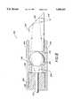
- FIG. 1is a partially cut away, partially exploded, perspective view of one embodiment of a laser probe.
- FIG. 2is a perspective view of the assembly of the laser probe of FIG. 1.
- FIG. 3is a partial cross-sectional view taken across line 3--3 in FIG. 2.
- FIG. 4is a schematic representation of the propagation path of laser light energy through the optical apparatus of the embodiment shown in FIGS. 1-3.
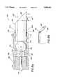
- FIG. 5is an elevation view in partial cross-section, of an alternative embodiment, showing a schematic representation of the propagation path of laser light energy through the optical apparatus.
- FIG. 6is a perspective view of the rod used in the alternative embodiment of the laser probe of FIG. 5.
- FIG. 7is a partial cross-sectional view of another embodiment the of the probe.
- FIG. 8is a cross-sectional view of still another embodiment of the laser probe.
- FIG. 8ais a cross-sectional view of a modified laser probe of FIG. 8.
- FIG. 8bis a perspective view of the rod used in the modified laser probe of FIG 8a.
- FIG. 9is a partial cross-sectional view of a variant of the laser probe of FIG. 8.
- FIG. 10is a partial cross-sectional view in perspective of an eye of a mammal showing the laser probe in use during an anterior capsulotomy procedure.
- FIG. 11is a partial cross-sectional view in perspective of an eye of a mammal showing the laser probe in use during a phacoemulsification procedure with irrigation.
- the probe 10comprises an elongate housing 14, an optical fiber 18 and an optical apparatus 22.
- the maximum diameter of the housing 14is preferably no more than 2.5 mm.
- the housing 14comprises a fiber holder comprising an axially elongate hollow shaft, 26 and a head element 30 at the distal end of the shaft 26.
- distaldesignates the direction away from the laser light source, to which the probe is optically coupled.
- proximalshall mean the direction toward the laser light source 34.
- longitudinalshall be used to refer to a direction corresponding to an imaginary line running between proximal and distal ends. In FIG. 1, a portion of the shaft 26 is cut away to reveal the fiber 18 extending therethrough.
- the head element 30is contoured for smooth insertion into interior portions of a mammal. In order to allow the head element 30 to be withdrawn from the mammal without snagging, the head element is generally symmetrical about the axis for insertion. The head element 30 is also smoothly contoured at its proximal and distal ends in order to prevent snagging upon insertion or withdrawal of the probe 10. As an alternative, the entire probe 10 can be housed within an outer housing (not shown) which can be contoured for smooth insertion and withdrawal without snagging.
- the head element 30is preferably constructed from metal, such as aluminum or stainless steel. As best seen in FIG. 3, the head element 30 has a hollow space including a longitudinal tubular cavity 38 and a transverse tubular cavity 39, which allow for insertion of the optical fiber 18 and optical apparatus 22 therethrough, respectively.
- the transverse tubular cavity 39extends through the head element 30 to form top and bottom openings in the head element 30.
- the optical apparatus 22is positioned into the head element through the transverse tubular cavity 39. As will be explained in more detail below, the optical apparatus 22 is held in place by crimping of the head element material.
- the hollow shaft 26, which extends into a proximal end of the longitudinal tubular cavity 38,can, advantageously, be formed from stainless steel hypodermic tubing.
- the longitudinal tubular cavity 38extends from the proximal opening into the transverse tubular cavity.
- the diameter of the longitudinal cavity 38is substantially the same as the outer diameter of the hollow shaft 26.
- the inner diameter of the shaft 26is slightly larger than the outer diameter of the optical fiber 18.
- the optical fiber 18is mounted in the hollow shaft 26.
- the head element 30 and hollow shaft 26together form a housing 14 for the optical fiber 18 and optical apparatus 22.
- the head element 30 and hollow shaft 26can be held together by any suitable method, such as by gluing with cyanoacrylate or by press fitting, brazing, soldering, or the like.
- the head element 30 and hollow shaft 26can be formed as a unitary whole.
- the optical fiber 18is used to conduct a laser light beam towards the housing 14 and ultimately into the optical apparatus 22. Accordingly, the optical fiber 18 is optically connected at its proximal end to the laser light source.
- a preferred optical fiber 18is a fluoride-based fiber, such as zirconium fluoride fiber having a numerical aperture of 0.2, which will produce an output cone of light having half angle of 11.5°.
- Aluminum fluoride fibercan also be provided.
- the fiber 18is provided with a core and cladding of zirconium fluoride and a jacket of U.V. curable acrylate.
- the fluoride-based fiberis in disposable, single-use form.
- the optical fiber 18is fixedly mounted in the tubular shaft 26 by a sleeve 58 comprising a tubular piece of material with an inner diameter slightly larger than the optical fiber 18 and an outer diameter slightly smaller than the inner diameter of the shaft 26.
- the fiber 18can be bonded in place with glue or other materials.
- the optical apparatus 22(described hereinbelow) forms a single integral whole.
- the optical apparatus 22receives laser light from the optical fiber 18 along the longitudinal axis of the optical fiber.
- the optical apparatus 22is formed from a dielectric material which is transparent to the beam of laser energy emanating from the optical fiber 18.
- a dielectric materialwhich is transparent to the beam of laser energy emanating from the optical fiber 18.
- sapphireis a preferred dielectric substance for formation of the optical apparatus 22.
- sapphireis readily machined into a variety of shapes useful as optical elements in the practice of the present invention.
- the optical apparatus 22is configured to redirect laser energy coming from the optical fiber 18 at an angle to the longitudinal axis of the optical fiber.
- the optical apparatus 22comprises a diverter portion 62 and an intensifier portion 63.
- the diverter portion 62reflects the laser energy output from the optical fiber 18.
- the diverter portion 62comprises a reflecting surface which is planar and is oriented at a predetermined angle relative to the propagation path of the light incident thereon.
- the reflecting surfaceis formed by a coating of reflective material which is 99.7% reflective at 2.94 ⁇ m (R max ).
- the optical apparatus 22is provided with two notches 64.
- the outer surfaces of the head element 30can be crimped onto the notches 64, thereby fastening the optical apparatus 22 to the head element 30.
- this cavity 65can be filled or covered in order to protect the reflecting surface.
- laser light energy entering the optical apparatus 22 from the optical fiber 18will propagate through the optical element along its axis of egress from the fiber 18 until it reaches the diverter portion 62 of the apparatus 22.
- the diverter portion 62is optically aligned and spaced from the optical fiber such that the output cone of laser light energy will cover the planar surface of the diverter portion 62 without significant amounts of laser energy loss.
- the distance 70 between the distal end of the fiber 18 and the proximal face of the optical element 22, measured along the longitudinal axis of the fibernot exceed 0.02 inches. If the distance 70 exceeds this length, too much laser light energy may diverge outside of the reflective surface of the diverter portion 62.
- Laser light energy reaching the diverter portion 62is redirected at an angle which depends on the geometry of the diverting portion 62.
- the diverter portion 62comprises a planar reflecting surface, such as that shown in FIGS. 1-4
- the lightwill be redirected at an angle corresponding to the angle of incidence of the laser light energy on the reflecting surface 68.
- the reflecting surface 68 of the preferred embodimentis disposed at an angle of 45° relative to the longitudinal axis of the light output from the optical fiber. As seen in FIG. 4, this will produce an angle of divergence of the laser light energy of 90° relative to its initial axis of propagation.
- the reflecting surface 68can be configured to provide any desired angle of divergence; particularly those angles greater than 30°, and more particularly greater than 45°.
- the intensifier portion 63 of the optical apparatus 22is disposed to receive the laser light energy that is redirected by the diverter portion 62.
- the intensifier portion 63serves to concentrate the redirected light beam.
- the intensifier portion 63can comprise a refracting surface, such as a focusing lens or a tapered tip, which produces the desired intensifying effect.
- the refracting surfaceis, advantageously, formed from the same dielectric material as the remainder of optical apparatus 22.
- the refracting surfacecomprises a hemispherical lens 74.
- the hemispherical lens 74is disposed at the end of a cylindrical rod portion 78 of the optical apparatus 22 which serves as a waveguide portion.
- the waveguide portion 78guides the redirected light reflecting from the reflecting surface 68 toward the refracting surface.
- the hemispherical lens 74has a radius of curvature equal to the radius of the cylindrical rod portion 78.
- the hemispherical lens 74focuses laser light energy emanating from the shaft portion 78 to focal point 79.
- One feature of the refracting surface 74is that it has a focal point 79 very close to the point of exit of laser light exiting therethrough. Preferably, this focal point is less than one millimeter from the refracting surface.
- an elongate housing 114having a maximum diameter of 2.5 mm or less, the housing 114 comprises a head element 104 and a fiber holder 126, each of which is formed by an axially elongate hollow shaft, such as by hypodermic tubing.
- the outer diameter of the fiber holder 126is approximately equal to the inner diameter of the head element 104, such that a distal end of the fiber holder 126 fits within a proximal end of the head element 104.
- the head element 104has a circular opening 106 which provides access to the interior hollow portion of the housing 114 and also provides a route for egress of laser light energy.
- the embodiment 20 shown by FIG. 5comprises an optical fiber 118.
- the optical fiber 118may be the same as the optical fiber 18, described above in connection with FIGS. 1-3.
- the optical fiber 118is connected to laser light source, such that laser light energy is transmitted through the optical fiber 118 in a longitudinal direction from proximal to distal.
- the optical fiber 118is of smaller diameter than the inner diameter of the fiber holder 126, and thus a tubular optical fiber sleeve 158 is used to hold the optical fiber 118 in position within the housing 114.
- the fiber sleeve 158has inner and outer diameters of a size sufficient to substantially fill the annular space between the fiber holder 126 and the optical fiber 118.
- the distal end of the optical fiber 118is preferably co-terminous with the distal end of the fiber sleeve 158.
- the fiber sleeve 158can be held to both the fiber holder 126 and the optical fiber 118 by interference fit.
- U.V. curable epoxy gluecan be used to hold the sleeve 158.
- the optical apparatuscomprises separate components and is not unitary.
- a diverter portion 162 of the optical apparatuscomprises a reflecting surface 168 formed by a reflective coating on the end of a sapphire rod 170.
- This rod 170has a diameter slightly smaller than the inner diameter of the head element 104.
- the rod 170can be inserted into the head element 104 in order to position the reflecting surface 168 such that the reflecting surface 168 directs laser light energy out of the head element 104 through the opening 106.
- the rod 170is provided with a disk 172 at its distal end which serves to prevent insertion of the rod 170 into the housing 104 further than the length of the rod 170.
- the rod 170 and disk 172are preferably constructed from a single unitary piece of material.
- the disk 172preferably has a diameter equal to the outer diameter of the head element 104, and is provided with curved corners at its distal end in order to create a smooth contour at the distal end of the probe 104, thereby allowing for smooth insertion and removal of the probe 100.
- an intensifier of the optical apparatuscomprises a microball 174, having a spherical surface for refracting light.
- the microball 174is preferably formed from dielectric material, such as sapphire, and can optionally be coated with an anti-reflective coating to increase optical transmission through the microball 174.
- Sapphire microballs 174are, advantageously, easily fabricated, readily available and commonly used as couplers for fiber-optic cables. These microballs 174 are also available in sizes of 2.2 mm or less.
- the microball 174can be held on to the housing 114 by gluing it to the opening 106 with U.V. curable epoxy glue. Because the reflecting surface 168 is aligned to direct laser light energy from the optical fiber 118 toward the opening 106, placing the microball 174 within the opening 106 allows the microball 174 to perform its intensifying function on the light energy passing therethrough.
- An optional feature of the optical apparatus of the various embodiments of laser probes useful in the present inventionis a collimator.
- the collimatorserves to substantially collimate the laser light energy emanating from the optical fiber prior to striking the diverting portion.
- the collimator of the optical apparatuscomprises a collimating microball 182, similar to the microball 174 described above in connection with the intensifier.
- the collimating microball 182is positioned between the optical fiber 118 and the diverter 162, immediately distal (e.g., about 0.02 inches) of the distal end of the optical fiber. It is important that the distance between the microball 182 and the fiber 118 be relatively small so as to cause collimation rather than focusing. Thus, light emanating from the distal end of the optical fiber 118 is collimated before reaching the reflecting surface 168. Such collimation of the laser light energy serves to reduce or eliminate spherical aberrations of the light passing through the microball 174.
- the probe 200comprises a fiber holder shaft 226 and a head element 230.
- the head element 230is contoured for smooth insertion and withdrawal.
- the head element 230has a longitudinal tubular cavity 238 and a transverse cavity 239.
- the diameter of the transverse cavity 239is constricted at the bottom relative to the remaining portion of the cavity 239, which is substantially tubular.
- a ledge 246is formed within the transverse cavity 239.
- the optical fiber 218 of this embodimentis fit into the head element 230 in a manner similar to that described above in connection with FIGS. 1-4.
- the optical apparatus of this embodimentcomprises separate pieces, namely a collimator 273, a diverter 262 and an intensifier 266.
- the collimator 273 and the intensifier portion 266comprise microballs, optionally coated with an anti-reflective coating.
- the diverter 262comprises a sapphire rod polished at a 45° angle at its distal end.
- the angled portionis coated with a reflective coating and forms a reflecting surface 268.
- the diameter of the rodis slightly smaller than the diameter of the longitudinal cavity 238 so that the diverter can be inserted therethrough.
- the intensifier microball 266rests on the ledge 246 and the diverter 266 is inserted through the longitudinal cavity 238 such that the microball 266 is held in the space between the ledge 246 and the diverter portion 268.
- the collimator microball 273, like the diverter portion 266,has a diameter slightly smaller than the diameter of the longitudinal cavity 238, and is inserted proximally of the diverter portion 266.
- the optical fiber 218 within the shaft 226is inserted into the longitudinal cavity 238.
- the shaft 226is held to the proximal end of the head element 230 with U.V. curable glue.
- the diverter portion 266 and the collimator microball 273are held within the portion of the longitudinal cavity 239 distal of the shaft 226.
- the probe 300comprises an optical fiber 318, a head element 330 and a fiber holder 358.
- the fiber holder 358serves to provide a grip for the operator of the probe 300 and also serves as a sleeve for the optical fiber 318.
- the head element 330has a tubular longitudinal cavity 338 having proximal, middle and distal sections.
- the middle sectionhas a constricted diameter relative to the proximal and distal sections of the cavity 338.
- the proximal section of the cavity 338is threaded to accept a threaded portion 392 of the fiber holder 358.
- the optical apparatus of the probe 300comprises an intensifier 366 and a diverter 362.
- the intensifiercomprises a spherical microball which is disposed in the distal section, and which rests on a ledge 346 formed by the constricted diameter of the middle section of the longitudinal cavity 338.
- the diverter 362comprises a sapphire rod polished at a 45° angle at its distal end. The angled portion is coated with a reflective coating to form a reflecting surface 368. The diameter of the rod is slightly smaller than the diameter of the longitudinal cavity 338 so that the diverter can be inserted therethrough.
- the diverter 362can extend beyond the distal end of the head element 330 as shown, or can be encased by the head element 330, with a hole at the point of emission of laser light energy. If the diverting portion extends beyond the distal end of the head element 330, the exposed sapphire can optionally be coated with a protective over-coat.
- the distance between the distal end of the fiber 318 and the proximal portion of the intensifier microball 366, and the distance from the distal portion of the intensifier microball and the reflecting surfaceare selected so as to produce a focal point 379 a desired distance (e.g., less than 1 mm) from the bottom of the diverter 362.
- the distance from the intensifier microball 366 and diverter 362can also be manipulated to provide the desired focal point 379.
- an input surface 370 of the diverter 362is touching or almost touching the intensifier microball 366 in order to prevent axial movement of the microball 366.
- the diverter 362can be held in place by providing a notch 364 on the head element 330 and crimping the notch 364 to the diverter 362. If desired, the input surface 370 of the diverter 362 and the entire or proximal surface of the intensifier microball 366 may be coated with an anti-reflective coating to minimize reflection.
- the probe 300is inserted into an internal portion of a mammal (e.g. an eye cavity) such that the rod 362 is surrounded by tissue and the portion of the rod extending from the housing is in contact with the tissue, although in the embodiment disclosed, the light beam is redirected by reflection, it will be understood that, by eliminating the reflective coating so that the light passes through the angled output face, redirection by refraction could be achieved. Such refraction is due to differences in refractive index at the angled output face. Redirection of the light beam by refraction may be similarly achieved by utilizing a bare rod, such as an optical fiber, and cleaving the end of the fiber of an angle (e.g. 45°) to cause the light output from the fiber to be deflected. Nevertheless, use of the reflective coating is preferred because a greater angle of deflection is possible.
- a mammale.g. an eye cavity
- FIG. 8athere is shown a probe 400 that is a modification of the laser probe 300 of FIG. 8.
- the microball 366is placed with its center 395 at its focal distance (f) from the distal end of the fiber 318. Placing the microball 366 in this position will achieve collimation of light incident thereon.
- nthe index of refraction
- Rthe radius 394 of the lens.
- the index of refraction of the lensis 1.72.
- the collimated lighttravels along the longitudinal axis of the probe 400 until meeting the reflecting surface 368.
- the reflecting surface 368diverts the light in a direction along an output axis 550 which is at an angle relative to the longitudinal axis of the probe 400.
- the preferred angle of the output axisis perpendicular to the longitudinal axis of the probe 400.
- angles greater or less than 90°are preferred.
- the reflecting surface 368is transparent and requires no reflective coating. Rather, reflection occurs due to the total internal reflection achieved from the differences in the indices of refraction between the material of the rod 362 and the material surrounding the probe 400.
- the rod 362is sapphire, having an index of refraction (n) of 1.7 with light produced by the Erbium:YAG laser having a wavelength of 2.94 ⁇ m.
- the probe 400functions to reflect light in substantially the same manner in a fluid environment (e.g. H 2 0) as in air because the refractive index difference between the fluid and the sapphire rod 362 is sufficiently great to cause total internal reflection to occur at the surface 368.
- a fluid environmente.g. H 2 0
- the rod 362comprises a sapphire rod of circular cross section which is polished at a 45° angle at its distal end to form the reflecting surface 368.
- the curved bottom output surface 399 of the rod 362acts as a cylindrical lens to focus the collimated light into a more linear form.
- the lens action of the output surface 399tends to be negated due to the higher index of refraction of the fluid and/or due to the contact with tissue at the cylindrical surface.
- the modified laser probe 400when used in internal portions of a mammalian body, such as in the eye, the light exiting the probe will be in a roughly tubular form.
- the probeis transparent to allow the user of the probe 400 to view the point of contact of the laser light energy on tissues or other materials. This is particularly advantageous in surgeries, such as anterior capsulotomies, where the probe would otherwise obscure the contact point of the light energy.
- Another advantage of the probe 400 of FIG. 8ais that the wedge-shaped end of the probe, formed by the angled reflecting surface 368, can be used as a tool to physically manipulate tissues without the need to insert an additional tool.
- the point of contactcan generally be seen due to the energy released by the tissues after coming into contact with the laser energy from the probe 400.
- the tissueabsorbs the collimated infra-red light emitted from the probe along the output axis 550 and causes a laser-tissue interaction to occur.
- This interactiongenerally results in the release of light of a wide spectrum, including visible light, at many different angles.
- much of the light released by laser-tissue interactionwill strike the reflecting surface 368 at an angle less than the critical angle.
- Even without release of significant quantities of light by laser-tissue interactionthe interaction can be seen by the formation of an incision or other effect on the tissue by the laser.
- the operator of the probecan look through the transparent reflecting surface 368 along a viewing axis 525 to view the visible light from the tissue during operation of the probe 400.
- the viewing axisis generally perpendicular to the longitudinal axis of the probe 400.
- all surfacesare polished with optical grade (e.g. 0.3 ⁇ m) polish, including the distal end of the fiber 318. Without this polishing, specular reflections can occur which result in a dispersal of the energy passing through the probe 400.
- optical gradee.g. 0.3 ⁇ m
- one or more notches 364aare provided on the rod 362 which will allow the rod 362 to be held to the head element 330 by crimping of the head element at the position of each notch 364a.
- the laser probe 400can advantageously be configured to supply irrigation fluid or vacuum for aspiration as frequently employed with known phacoemulsification devices. Alternatively, irrigation and/or aspiration can be supplied from separate devices inserted into the region of use of the probe 400.
- a sealant 398such as epoxy glue is preferably provided at the junction between the rod 362 and the head element 330, to prevent entry of fluid into the cavity 338.
- the head element 330is elongated to extend beyond the diverter 362, and comprises an opening 306 to allow laser light energy to be emitted outside the head element 330 after it has been diverted by the diverter 362.
- a cap 394is inserted at the end of the head element 330.
- the cap 394comprises a rod portion 395 and a flange portion 396.
- the diameter of the rod portion 395is slightly smaller than the diameter of the longitudinal cavity 338 so that the rod portion 395 can be inserted therethrough.
- the rod portion 395is cut an angle which will complement the angle of end the diverter rod 362 to substantially completely fill the longitudinal cavity 338 at its end. Thus, if the diverter rod 362 is cut at a 45° angle, the rod portion 395 will also be cut at a 45° angle.
- the length of the rod portionis selected to substantially completely fill the end of the longitudinal cavity 338.
- the flange portion 396provides a smooth surface for easy insertion and withdrawal of the variant laser probe 310.
- the cap 394is held in place by crimping the notches 364 to the cap 394, thereby also preventing axial movement of the diverter rod 362.
- the laser probes 10, 100, 200, 300, 310, 400are useful in a wide variety of surgical procedures, including procedures such as described by Berlin in U.S. Pat. No. 4,846,172.
- the use of the laser probes 10, 100, 200, 300, 310, 400is especially advantageous in procedures where it is desired to operate a laser probe within a tightly confined space, such as within bodily tissues or a tightly confined body cavity or lumen.
- the probeallows a surgeon to direct laser energy from the side of the probe, thereby allowing laser energy to be directed around tight corners.
- the probecan be applied in a mammal
- ophthalmic procedures of many typesinclude ophthalmic procedures of many types.
- the probecan be used for cutting, phacoemulsification and phacoablation.
- corneal surgeriessuch as keratectomy or keratoplastomy
- glaucoma surgeriessuch as filtration procedures, trabeculoplasty, iridectomies or iridotomies
- cataract surgeriessuch as capsulotomy or cataract extraction
- vitreous surgeriessuch as cutting of the vitreous bands
- retinal surgerysuch as removal of retinal membrane or repair of retinal tears.
- Non-ophthalmic procedures on a mammal in which the probe is believed to be usefulinclude surgery within a joint, such as a knee, and procedures within long narrow passages, such as can be found within the cardiovascular system and the urethra.
- the intensity of the light input to the probeis regulated, depending on the procedure, to provide sufficient intensity to achieve the desired result such as cutting, welding, vaporization or coagulation of biotic material (e.g. tissue).
- the frequency of the pulseshould be in excess of 5 Hz, preferably 10 Hz-30 Hz or more.
- the energy thresholdis 5-10 mJ for cutting of the anterior capsule of the eye.
- energy levels of 30 mJ per pulseare less are preferred, with energy levels just above the energy threshold of 5-10 mJ/pulse being especially preferred.
- one procedure in which the probe is particularly usefulis in anterior capsulotomy of the eye.
- a small roughly circular incision 501 through one side of the sclera 502 of the eye 500is first made into the anterior chamber 516.
- This incisionis roughly 2.0-3.5 mm in diameter.
- the probeis preferably contained within a housing having a diameter of 2.5 mm or less. This is advantageous in anterior capsulotomies and other procedures within the eye because larger probes would require a larger incision.
- the use of large probesalso increases the risk that the probe will come into contact the cornea 512, iris 515 or other delicate tissues within the eye 500, resulting in damage to these tissues.
- the chamber 516can be filled with a viscoelastic material, such as "Healon".
- a viscoelastic materialsuch as "Healon”.
- the viscoelastic materialwill also hold tissues in position within the eye during the procedure.
- irrigation fluidsuch as balanced salt solution (BSS) can be continuously infused to maintain patency of the chamber 516.
- BSSbalanced salt solution
- the probe 400 or other laser probecan be inserted into the incision 501 along with the fiber 318 transmitting laser energy thereto.
- the probeis then manipulated to cut a circular incision (shown partially formed at 560 in FIG. 10) around a portion of the anterior capsule 524 adjacent the lens.
- the laser probe 400advantageously allows the operator to view the energy released from the surface of the capsule as laser light energy is applied.
- the laser light sourcemay be used in the procedure. However, it is preferred that the laser light source provide a smooth, non-serrated capsular margin, in order to enable a surgeon to make a clean circular out on the anterior capsule. A percussive device would not be appropriate, which would punch ragged holes in the capsule. Thus, the frequency of the laser pulse should be in excess of 10 Hz, preferably 20 Hz-30 Hz or more, as discussed above.
- a laser light source producing light at a wavelength readily absorbed by wateris provided.
- Use of wavelengths that are absorbed readily by wateris useful for ablation of tissues. Also, use of such wavelengths serves to prevent unwanted transmission and scatter of laser energy to adjacent or underlying tissues, resulting in minimal thermal damage to these tissues.
- the laser lightbe deliverable by an optical fiber to allow the user of the probe to deliver the laser light energy by hand. Hand delivery is important for allowing delicate manipulations within the eye and other tightly confined tissues.
- a preferred laser light sourceis an Erbium:YAG laser which produces laser light energy of wavelength 2.94 ⁇ m, a wavelength at which water has an absorbance peak.
- one preferred wavelength range for the light energy for use with the probe 400is the range from 2.8 ⁇ m to 3.0 ⁇ m.
- the Erbium:YAG laserprovides several additional advantages. First, the energy is non-ultraviolet, thereby allowing work in the eye with increased safety, obviating the need to use blocking elements or device to prevent retinal toxicity- Second, the Erbium:YAG light source can also be configured to provide the pulse frequency greater than 10 Hz needed to provide smooth cutting.
- the high absorbance by watermakes the laser safer, more controllable, and more precise-
- the laserhas a low thermal component, allowing for precise spatial confinement of energy deposition and reducing thermal damage and charring of intraocular tissues.
- the Erbium:YAG laseris relatively inexpensive to manufacture and maintain compared to certain other lasers.
- Laser light sourceswhich produce energy at other non-ultraviolet absorbance peaks of water, such as 2.1 ⁇ m, and are deliverable by optical fiber provide advantages similar to those provided by the Erbium:YAG laser.
- another preferred laser light sourceis the Holmium:YAG laser which is hand deliverable and provides laser light energy within the range of 1.9 ⁇ m to 2.2 ⁇ m.
- Delivering laser light energy by fiber 318provides the additional advantage of allowing use of the bare fiber through removal of the probe tip.
- the probe tipis removable by hand to expose the distal end of the fiber 318, thereby enabling use of the bare fiber end from the same hand held instrument.
- Use of the bare fiberis advantageous in many procedures, such as the excision of a vitreous band within the eye of a mammal.
- the surgeon or operator of the probemust look through the probe 400.
- the incision in the capsule 524is made with a transparent laser probe having an uncoated, transparent reflecting surface 368, such as the probe 400 of FIG. 8a
- the surgeoncan look through the surface 368 of the probe 400 to view the incision 560 at the point of contact 575 while the incision 560 is being cut.
- the surgeoncan look through the cornea 512, pupil 514 and the transparent reflecting surface 368 along the viewing axis 525.
- the viewing axis 525is generally parallel to the output axis 550, and in an especially preferred embodiment, the viewing axis 525 is collinear with the output axis 550.
- the cutout portion of the anterior capsule 524 inside the incision 560is removed to expose the underlying lens 528.
- this cut out portion of the lens 528can be manipulated using the wedge formed by the reflecting surface 368 on the probe 400.
- this wedgecan be used to manipulate other tissues inside the eye or elsewhere as well.
- the wedgehas also been found to be advantageous in readily allowing the user of the probe to separate planes of tissue, such as in separating fascia from muscle or separating the anterior capsule 524 from the underlying lens 528 within the eye 500.
- the lens 528can first be emulsified in a manner known to those of skill in the art, such as through phacoemulsification using an ultrasonic device.
- the laser probe 400can also be used for emulsification, preferably using a higher energy level than used for incision, e.g. 100 mJ/pulse.
- the probe 400can be used to deliver light energy to emulsify the lens within the completed capsular margin 600. There is less need for high frequency of laser light energy pulses during emulsification, thus frequencies of 5 Hz or less can be used.
- the high energy laser light energyexits the probe along output axis 550, and the lens tissue within the margin 600 contacted by the laser light can be viewed through the probe 400 as discussed above.
- the emulsified lens materialcan advantageously be removed using irrigation and aspiration supplied along with the probe 400.
- irrigation means 620is shown in FIG. 11.
- the use of irrigation means 620 and aspiration means for this purpose as part of a laser probeis well known, and has been described, for example in U.S. Pat. Nos. 4,846,172 and 4,784,132, the disclosures of which are hereby incorporated by reference.
- Irrigation and/or aspirationcan also be supplied as separate components, as is well known to those of skill in the art.
- the eye 500is ready for implantation of the IOL.
Landscapes
- Health & Medical Sciences (AREA)
- Life Sciences & Earth Sciences (AREA)
- Surgery (AREA)
- Physics & Mathematics (AREA)
- Optics & Photonics (AREA)
- Animal Behavior & Ethology (AREA)
- Engineering & Computer Science (AREA)
- Biomedical Technology (AREA)
- Heart & Thoracic Surgery (AREA)
- Nuclear Medicine, Radiotherapy & Molecular Imaging (AREA)
- Veterinary Medicine (AREA)
- Public Health (AREA)
- General Health & Medical Sciences (AREA)
- Ophthalmology & Optometry (AREA)
- Electromagnetism (AREA)
- Otolaryngology (AREA)
- Medical Informatics (AREA)
- Molecular Biology (AREA)
- Vascular Medicine (AREA)
- Laser Surgery Devices (AREA)
- Radiation-Therapy Devices (AREA)
Abstract
Description
Claims (24)
Priority Applications (2)
| Application Number | Priority Date | Filing Date | Title |
|---|---|---|---|
| US08/419,511US5688261A (en) | 1990-11-07 | 1995-04-07 | Transparent laser surgical probe |
| US08/841,865US6620154B1 (en) | 1990-11-07 | 1997-05-05 | Laser surgical probe |
Applications Claiming Priority (5)
| Application Number | Priority Date | Filing Date | Title |
|---|---|---|---|
| US61015590A | 1990-11-07 | 1990-11-07 | |
| US99967692A | 1992-12-30 | 1992-12-30 | |
| US13530993A | 1993-10-12 | 1993-10-12 | |
| US30747494A | 1994-09-16 | 1994-09-16 | |
| US08/419,511US5688261A (en) | 1990-11-07 | 1995-04-07 | Transparent laser surgical probe |
Related Parent Applications (1)
| Application Number | Title | Priority Date | Filing Date |
|---|---|---|---|
| US30747494AContinuation | 1990-11-07 | 1994-09-16 |
Related Child Applications (1)
| Application Number | Title | Priority Date | Filing Date |
|---|---|---|---|
| US08/841,865DivisionUS6620154B1 (en) | 1990-11-07 | 1997-05-05 | Laser surgical probe |
Publications (1)
| Publication Number | Publication Date |
|---|---|
| US5688261Atrue US5688261A (en) | 1997-11-18 |
Family
ID=27495151
Family Applications (2)
| Application Number | Title | Priority Date | Filing Date |
|---|---|---|---|
| US08/419,511Expired - Fee RelatedUS5688261A (en) | 1990-11-07 | 1995-04-07 | Transparent laser surgical probe |
| US08/841,865Expired - Fee RelatedUS6620154B1 (en) | 1990-11-07 | 1997-05-05 | Laser surgical probe |
Family Applications After (1)
| Application Number | Title | Priority Date | Filing Date |
|---|---|---|---|
| US08/841,865Expired - Fee RelatedUS6620154B1 (en) | 1990-11-07 | 1997-05-05 | Laser surgical probe |
Country Status (1)
| Country | Link |
|---|---|
| US (2) | US5688261A (en) |
Cited By (30)
| Publication number | Priority date | Publication date | Assignee | Title |
|---|---|---|---|---|
| WO1999044518A1 (en)* | 1998-03-04 | 1999-09-10 | Surgical Laser Technologies, Inc. | Laterally-emitting laser medical device |
| US5971755A (en)* | 1996-09-06 | 1999-10-26 | Kaltenbach & Voigt Gmbh & Co. | Laser instrument |
| US6039736A (en)* | 1998-09-29 | 2000-03-21 | Sherwood Services Ag | Side-Fire coagulator |
| WO2002056805A3 (en)* | 2001-01-18 | 2002-11-21 | Univ California | Minimally invasive glaucoma surgical instrument and method |
| US20030065324A1 (en)* | 1998-09-29 | 2003-04-03 | Platt Robert C. | Swirling system for ionizable gas coagulator |
| US20030093073A1 (en)* | 1999-10-05 | 2003-05-15 | Platt Robert C. | Articulating ionizable gas coagulator |
| US20040116951A1 (en)* | 2002-11-13 | 2004-06-17 | Rosengart Todd K. | Apparatus and method for cutting a heart valve |
| US20040165183A1 (en)* | 2001-01-23 | 2004-08-26 | Marquardt Brian J. | Optical immersion probe incorporating a spherical lens |
| US6852112B2 (en) | 1999-10-05 | 2005-02-08 | Sherwood Services Ag | Multi-port side-fire coagulator |
| US20090048594A1 (en)* | 2004-02-03 | 2009-02-19 | Sartor Joe D | Gas-enhanced surgical instrument with pressure safety feature |
| US7572255B2 (en) | 2004-02-03 | 2009-08-11 | Covidien Ag | Gas-enhanced surgical instrument |
| AU2005290208B2 (en)* | 2004-08-13 | 2009-08-20 | Biolase Technology, Inc. | Laser handpiece architecture and methods |
| KR100914142B1 (en) | 2009-01-16 | 2009-08-28 | 주식회사 루트로닉 | Optical fiber assembly for medical laser surgery |
| US7628787B2 (en) | 2004-02-03 | 2009-12-08 | Covidien Ag | Self contained, gas-enhanced surgical instrument |
| US7648503B2 (en) | 2006-03-08 | 2010-01-19 | Covidien Ag | Tissue coagulation method and device using inert gas |
| US7691102B2 (en) | 2006-03-03 | 2010-04-06 | Covidien Ag | Manifold for gas enhanced surgical instruments |
| US7833222B2 (en) | 2004-02-03 | 2010-11-16 | Covidien Ag | Gas-enhanced surgical instrument with pressure safety feature |
| US8123744B2 (en) | 2006-08-29 | 2012-02-28 | Covidien Ag | Wound mediating device |
| US8157795B2 (en) | 2004-02-03 | 2012-04-17 | Covidien Ag | Portable argon system |
| US8226642B2 (en) | 2008-08-14 | 2012-07-24 | Tyco Healthcare Group Lp | Surgical gas plasma ignition apparatus and method |
| US20140160486A1 (en)* | 2012-12-10 | 2014-06-12 | The Johns Hopkins University | Sapphire lens-based optical fiber probe for optical coherence tomography |
| ES2472542A1 (en)* | 2012-12-31 | 2014-07-01 | Universidad De Granada | Directional tissue ablation device |
| US20150146211A1 (en)* | 2013-11-27 | 2015-05-28 | Corning Incorporated | Optical coherence tomography probe |
| US20150265468A1 (en)* | 2014-03-21 | 2015-09-24 | Carl Zeiss Meditec Ag | Surgical system for opening the lens capsule in an eye |
| US20160038236A1 (en)* | 2013-04-01 | 2016-02-11 | Biolitec Pharma Marketing Ltd. | Device for tissue removal |
| US20160143782A1 (en)* | 2013-10-10 | 2016-05-26 | Gachon University Of Industry-Academic Cooperation Foundation | Illumination chopper |
| US9752935B2 (en) | 2014-08-29 | 2017-09-05 | Marqmetrix, Inc. | Portable analytical equipment |
| US9958324B1 (en) | 2017-02-15 | 2018-05-01 | MarqMetrix Inc. | Enclosed benchtop raman spectrometry device |
| US20190018195A1 (en)* | 2017-07-17 | 2019-01-17 | Joe D. Brown | Interchangeable forward or sidefiring tip with stand off catheter |
| US20220409043A1 (en)* | 2012-11-02 | 2022-12-29 | Amo Development, Llc | Laser eye surgery system |
Families Citing this family (40)
| Publication number | Priority date | Publication date | Assignee | Title |
|---|---|---|---|---|
| US7867186B2 (en) | 2002-04-08 | 2011-01-11 | Glaukos Corporation | Devices and methods for treatment of ocular disorders |
| US6638239B1 (en) | 2000-04-14 | 2003-10-28 | Glaukos Corporation | Apparatus and method for treating glaucoma |
| US6751379B2 (en)* | 2000-11-01 | 2004-06-15 | Intel Corporation | System and method for collimating and redirecting beams in a fiber optic system |
| AU2002258754B2 (en) | 2001-04-07 | 2006-08-17 | Glaukos Corporation | Glaucoma stent and methods thereof for glaucoma treatment |
| US7331984B2 (en) | 2001-08-28 | 2008-02-19 | Glaukos Corporation | Glaucoma stent for treating glaucoma and methods of use |
| IL156626A (en)* | 2003-06-24 | 2009-12-24 | Yeda Res & Dev | System for selective cell destruction |
| US7074040B2 (en)* | 2004-03-30 | 2006-07-11 | Ultradent Products, Inc. | Ball lens for use with a dental curing light |
| US7794490B2 (en)* | 2004-06-22 | 2010-09-14 | Boston Scientific Scimed, Inc. | Implantable medical devices with antimicrobial and biodegradable matrices |
| WO2006005038A2 (en)* | 2004-06-28 | 2006-01-12 | Optimedica Corporation | Method and device for optical ophthalmic therapy |
| US7356368B2 (en)* | 2004-07-21 | 2008-04-08 | Boston Scientific Scimed, Inc. | Light-activated anti-infective coatings and devices made thereof |
| US7213982B2 (en)* | 2004-10-07 | 2007-05-08 | Avago Technologies Fiber Ip (Singapore) Pte. Ltd. | Optoelectronic module with high coupling efficiency |
| EP1650839A1 (en)* | 2004-10-20 | 2006-04-26 | Wavelight Laser Technologie AG | Fiber laser arrangement |
| US8394084B2 (en) | 2005-01-10 | 2013-03-12 | Optimedica Corporation | Apparatus for patterned plasma-mediated laser trephination of the lens capsule and three dimensional phaco-segmentation |
| US9681985B2 (en)* | 2005-12-01 | 2017-06-20 | Topcon Medical Laser Systems, Inc. | System and method for minimally traumatic ophthalmic photomedicine |
| EP2088976B1 (en) | 2006-11-10 | 2019-07-03 | Glaukos Corporation | Uveoscleral shunt |
| US8568393B2 (en)* | 2007-03-13 | 2013-10-29 | Topcon Medical Laser Systems, Inc. | Computer guided patterned laser trabeculoplasty |
| US8968221B2 (en) | 2007-04-17 | 2015-03-03 | Bwt Property, Inc. | Apparatus and methods for phototherapy |
| WO2009135213A2 (en)* | 2008-05-02 | 2009-11-05 | Zelickson Brian D | Laser energy devices and methods for soft tissue removal |
| US20090287199A1 (en)* | 2008-05-19 | 2009-11-19 | Brian Hanley | Side-firing laser fiber with protective tip and related methods |
| US20090287200A1 (en)* | 2008-05-19 | 2009-11-19 | Brian Hanley | Side-firing laser fiber with glass fused reflector and capillary and related methods |
| US8882685B2 (en) | 2008-05-27 | 2014-11-11 | Bwt Property, Inc. | Apparatus and methods for phototherapy |
| US20090326525A1 (en)* | 2008-06-26 | 2009-12-31 | Jessica Hixon | Laser fiber capillary apparatus and method |
| US20110255828A1 (en)* | 2008-12-22 | 2011-10-20 | Ams Research Corporation | Sapphire-based delivery tip for optic fiber |
| DE102009015911A1 (en)* | 2009-04-03 | 2010-10-07 | Carl Zeiss Meditec Ag | Device and method for removing a lenticle from the cornea |
| WO2012071476A2 (en) | 2010-11-24 | 2012-05-31 | David Haffner | Drug eluting ocular implant |
| USD638944S1 (en) | 2009-09-22 | 2011-05-31 | Ultradent Products, Inc. | Dental illumination device |
| US8724941B2 (en)* | 2010-02-22 | 2014-05-13 | Boston Scientific Scimed, Inc. | Methods and apparatus related to a side-fire optical fiber having a robust distal end portion |
| US10994992B2 (en) | 2011-01-20 | 2021-05-04 | Technion Research & Development Foundation Limited | Method and system for manipulating a cell |
| US9113934B2 (en)* | 2011-05-16 | 2015-08-25 | Covidien Lp | Optical energy-based methods and apparatus for tissue sealing |
| US9411103B2 (en)* | 2011-11-22 | 2016-08-09 | The University Of North Carolina At Charlotte | Contact focusing hollow-core fiber microprobes |
| CA2868341C (en) | 2012-03-26 | 2021-01-12 | Glaukos Corporation | System and method for delivering multiple ocular implants |
| US9592151B2 (en) | 2013-03-15 | 2017-03-14 | Glaukos Corporation | Systems and methods for delivering an ocular implant to the suprachoroidal space within an eye |
| CN111050682B (en)* | 2017-08-30 | 2023-11-03 | 莱谱有限责任公司 | Non-ablative photonic devices and related methods |
| US11116625B2 (en) | 2017-09-28 | 2021-09-14 | Glaukos Corporation | Apparatus and method for controlling placement of intraocular implants |
| CN110573117B (en) | 2017-10-06 | 2021-10-26 | 格劳科斯公司 | Systems and methods for delivering multiple ocular implants |
| USD846738S1 (en) | 2017-10-27 | 2019-04-23 | Glaukos Corporation | Implant delivery apparatus |
| US10816789B2 (en) | 2018-01-24 | 2020-10-27 | Canon U.S.A., Inc. | Optical probes that include optical-correction components for astigmatism correction |
| US10806329B2 (en)* | 2018-01-24 | 2020-10-20 | Canon U.S.A., Inc. | Optical probes with optical-correction components |
| US12263533B2 (en)* | 2021-01-13 | 2025-04-01 | Coherent, Inc. | Spectrally broadening ultrashort-pulse compressor |
| DE102023104405A1 (en) | 2023-02-23 | 2024-08-29 | Laser Zentrum Hannover E.V. | Endoscope and method of operation |
Citations (50)
| Publication number | Priority date | Publication date | Assignee | Title |
|---|---|---|---|---|
| US3348547A (en)* | 1964-10-16 | 1967-10-24 | American Optical Corp | Photocoagulating apparatus |
| US3494354A (en)* | 1964-09-30 | 1970-02-10 | Tokyo Shibaura Electric Co | Flexible endoscope for use in cancer diagnosis |
| US3996935A (en)* | 1969-02-14 | 1976-12-14 | Surgical Design Corporation | Surgical-type method for removing material |
| DE2828322A1 (en)* | 1978-06-28 | 1980-01-10 | Eichler Juergen | Laser instrument for medical use - comprises long thin tube with lens at distal end and includes light conductive fibre |
| US4233493A (en)* | 1974-05-21 | 1980-11-11 | Nath Guenther | Apparatus for applying intense light radiation to a limited area |
| US4269648A (en)* | 1980-03-10 | 1981-05-26 | Gte Laboratories Incorporated | Method for mounting microsphere coupling lenses on optical fibers |
| EP0073617A1 (en)* | 1981-08-25 | 1983-03-09 | Peter John Pembery | Laser dental handpiece |
| US4556057A (en)* | 1982-08-31 | 1985-12-03 | Hamamatsu Tv Co., Ltd. | Cancer diagnosis device utilizing laser beam pulses |
| US4576177A (en)* | 1983-02-18 | 1986-03-18 | Webster Wilton W Jr | Catheter for removing arteriosclerotic plaque |
| US4597380A (en)* | 1982-09-30 | 1986-07-01 | Laser Industries Ltd. | Endoscopic attachment to a surgical laser |
| US4608980A (en)* | 1984-04-13 | 1986-09-02 | Osada Electric Co., Ltd. | Laser hand piece |
| US4625724A (en)* | 1984-07-25 | 1986-12-02 | Fuji Photo Optical Co., Ltd. | Laser vascular anastomosis apparatus |
| US4638800A (en)* | 1985-02-08 | 1987-01-27 | Research Physics, Inc | Laser beam surgical system |
| WO1987001195A1 (en)* | 1985-08-14 | 1987-02-26 | Fraunhofer-Gesellschaft Zur Förderung Der Angewand | Process for determining a geometrical parameter for crimped, irregularly structured fibres |
| EP0214712A1 (en)* | 1985-07-31 | 1987-03-18 | C.R. Bard, Inc. | Infrared laser catheter apparatus |
| GB2182565A (en)* | 1985-11-08 | 1987-05-20 | Micra Ltd | Surgical knives |
| US4693244A (en)* | 1984-05-22 | 1987-09-15 | Surgical Laser Technologies, Inc. | Medical and surgical laser probe I |
| US4718417A (en)* | 1985-03-22 | 1988-01-12 | Massachusetts Institute Of Technology | Visible fluorescence spectral diagnostic for laser angiosurgery |
| WO1988000454A1 (en)* | 1986-07-17 | 1988-01-28 | Quotidian No. 100 Pty. Limited | Correction of incompetent venous valves |
| US4740047A (en)* | 1985-03-26 | 1988-04-26 | Hatachi Cable, Ltd. | Fiber for lateral beaming of laser beam |
| US4744360A (en)* | 1986-12-18 | 1988-05-17 | Bath Patricia E | Apparatus for ablating and removing cataract lenses |
| WO1988003595A1 (en)* | 1986-11-14 | 1988-05-19 | Bona Richard R | Temporary isolation structure |
| US4760840A (en)* | 1986-12-16 | 1988-08-02 | The Regents Of The University Of California | Endoscopic laser instrument |
| US4765336A (en)* | 1986-01-20 | 1988-08-23 | Carl-Zeiss-Stiftung | Supplement arrangement for a slit-lamp apparatus for treating the eye by means of laser rays |
| US4784135A (en)* | 1982-12-09 | 1988-11-15 | International Business Machines Corporation | Far ultraviolet surgical and dental procedures |
| US4785815A (en)* | 1985-10-23 | 1988-11-22 | Cordis Corporation | Apparatus for locating and ablating cardiac conduction pathways |
| EP0293126A1 (en)* | 1987-05-20 | 1988-11-30 | Keeler Limited | Photocoagulation apparatus |
| US4796969A (en)* | 1985-12-16 | 1989-01-10 | Polaroid Corporation | Fiber optic relay connector |
| WO1989003202A2 (en)* | 1987-10-14 | 1989-04-20 | Schneider Richard T | Method and apparatus for laser emulsification |
| US4830453A (en)* | 1984-11-21 | 1989-05-16 | U.S. Philips Corp. | Device for optically coupling a radiation source to an optical transmission fiber |
| US4846154A (en)* | 1988-06-13 | 1989-07-11 | Macanally Richard B | Dual view endoscope |
| US4849859A (en)* | 1986-04-22 | 1989-07-18 | Kabushiki Kaisha Morita Seisakusho | Laser-type handpiece |
| US4848336A (en)* | 1981-12-11 | 1989-07-18 | Fox Kenneth R | Apparatus for laser treatment of body lumens |
| DE3816456A1 (en)* | 1987-11-20 | 1989-11-23 | Hohla Kristian | Device for the surgical removal of material layers |
| US4887592A (en)* | 1987-06-02 | 1989-12-19 | Hanspeter Loertscher | Cornea laser-cutting apparatus |
| US4913132A (en)* | 1986-07-25 | 1990-04-03 | Noble Gabriel | Myringotomy instrument |
| US4917084A (en)* | 1985-07-31 | 1990-04-17 | C. R. Bard, Inc. | Infrared laser catheter system |
| EP0368512A2 (en)* | 1988-11-10 | 1990-05-16 | Premier Laser Systems, Inc. | Multiwavelength medical laser system |
| EP0392951A2 (en)* | 1989-04-10 | 1990-10-17 | Guy Levy | Device and method utilising laser effect, for the vaporization and fusion of materials and various tissues |
| US4983009A (en)* | 1987-12-03 | 1991-01-08 | Bt&D Technologies Limited | Light transmitting device utilizing indirect reflection |
| US4988163A (en)* | 1989-08-17 | 1991-01-29 | Quantronix Corp. | Infrared laser system for surgical purposes employing compound fiber probe |
| US5041121A (en)* | 1988-12-21 | 1991-08-20 | Messerschmitt-Bolkow-Blohm Gmbh | Shock wave generator |
| US5057098A (en)* | 1987-05-01 | 1991-10-15 | Ophthalmocare, Inc. | Apparatus and method for extracting cataract tissue |
| US5078711A (en)* | 1988-08-11 | 1992-01-07 | Kabushiki Kaisha Morita Seisakusho | Laser irradiation device capable of varying irradiation angle |
| US5102410A (en)* | 1990-02-26 | 1992-04-07 | Dressel Thomas D | Soft tissue cutting aspiration device and method |
| US5242437A (en)* | 1988-06-10 | 1993-09-07 | Trimedyne Laser Systems, Inc. | Medical device applying localized high intensity light and heat, particularly for destruction of the endometrium |
| US5246436A (en)* | 1991-12-18 | 1993-09-21 | Alcon Surgical, Inc. | Midinfrared laser tissue ablater |
| US5253312A (en)* | 1992-06-26 | 1993-10-12 | Cytocare, Inc. | Optical fiber tip for use in a laser delivery system and a method for forming same |
| US5254114A (en)* | 1991-08-14 | 1993-10-19 | Coherent, Inc. | Medical laser delivery system with internally reflecting probe and method |
| US5344418A (en)* | 1991-12-12 | 1994-09-06 | Shahriar Ghaffari | Optical system for treatment of vascular lesions |
Family Cites Families (26)
| Publication number | Priority date | Publication date | Assignee | Title |
|---|---|---|---|---|
| US3136310A (en) | 1960-01-18 | 1964-06-09 | Bausch & Lomb | Optical catheter |
| IL40602A (en) | 1972-10-17 | 1975-07-28 | Panengeneering Ltd | Laser device particularly useful as surgical scalpel |
| US3982541A (en) | 1974-07-29 | 1976-09-28 | Esperance Jr Francis A L | Eye surgical instrument |
| US4122853A (en) | 1977-03-14 | 1978-10-31 | Spectra-Med | Infrared laser photocautery device |
| US4313431A (en) | 1978-12-06 | 1982-02-02 | Messerschmitt-Boelkow-Blohm Gesellschaft Mit Beschraenkter Haftung | Endoscopic apparatus with a laser light conductor |
| US4316467A (en) | 1980-06-23 | 1982-02-23 | Lorenzo P. Maun | Control for laser hemangioma treatment system |
| JPS587235A (en) | 1981-07-07 | 1983-01-17 | 住友電気工業株式会社 | laser scalpel |
| JPS5821387A (en) | 1981-07-29 | 1983-02-08 | Olympus Optical Co Ltd | Irradiator for laser |
| US4583539A (en) | 1982-01-12 | 1986-04-22 | Cornell Research Foundation, Inc. | Laser surgical system |
| US4784132A (en) | 1983-03-25 | 1988-11-15 | Fox Kenneth R | Method of and apparatus for laser treatment of body lumens |
| US4551129A (en) | 1983-04-08 | 1985-11-05 | Coleman D Jackson | Technique and apparatus for intraocular and microsurgery including lighter-irrigator hypodermic tube |
| DE3319203C2 (en) | 1983-05-27 | 1986-03-27 | Fa. Carl Zeiss, 7920 Heidenheim | Device for dose measurement during photocoagulation |
| JPS60148566A (en) | 1984-01-13 | 1985-08-05 | 株式会社東芝 | Laser treatment device |
| US4558698A (en) | 1984-03-01 | 1985-12-17 | Dell Lawrence W O | Laser canaliculostomy eye-treatment |
| US4538608A (en) | 1984-03-23 | 1985-09-03 | Esperance Jr Francis A L | Method and apparatus for removing cataractous lens tissue by laser radiation |
| US4648892A (en)* | 1985-03-22 | 1987-03-10 | Massachusetts Institute Of Technology | Method for making optical shield for a laser catheter |
| US4819632A (en) | 1986-05-19 | 1989-04-11 | Davies David H | Retrolasing catheter and method |
| US4672961A (en) | 1986-05-19 | 1987-06-16 | Davies David H | Retrolasing catheter and method |
| US4825865A (en) | 1987-05-01 | 1989-05-02 | Jerry Zelman | Apparatus and method for extracting cataract tissue |
| US4846172A (en) | 1987-05-26 | 1989-07-11 | Berlin Michael S | Laser-delivery eye-treatment method |
| DE3723674A1 (en) | 1987-07-16 | 1989-01-26 | Biotronik Mess & Therapieg | CONTROLLABLE CATHETER FOR TRANSMITTING LASER RADIATION |
| DE8915909U1 (en)* | 1989-07-25 | 1992-02-06 | Richard Wolf Gmbh, 7134 Knittlingen | Laser light applicator |
| JP2852774B2 (en)* | 1989-11-22 | 1999-02-03 | 株式会社エス・エル・ティ・ジャパン | Diagnostic device for living tissue and treatment device provided with the diagnostic device |
| US5084043A (en) | 1990-01-12 | 1992-01-28 | Laserscope | Method for performing a percutaneous diskectomy using a laser |
| US5257991A (en)* | 1990-11-15 | 1993-11-02 | Laserscope | Instrumentation for directing light at an angle |
| US5163935A (en)* | 1991-02-20 | 1992-11-17 | Reliant Laser Corporation | Surgical laser endoscopic focusing guide with an optical fiber link |
- 1995
- 1995-04-07USUS08/419,511patent/US5688261A/ennot_activeExpired - Fee Related
- 1997
- 1997-05-05USUS08/841,865patent/US6620154B1/ennot_activeExpired - Fee Related
Patent Citations (50)
| Publication number | Priority date | Publication date | Assignee | Title |
|---|---|---|---|---|
| US3494354A (en)* | 1964-09-30 | 1970-02-10 | Tokyo Shibaura Electric Co | Flexible endoscope for use in cancer diagnosis |
| US3348547A (en)* | 1964-10-16 | 1967-10-24 | American Optical Corp | Photocoagulating apparatus |
| US3996935A (en)* | 1969-02-14 | 1976-12-14 | Surgical Design Corporation | Surgical-type method for removing material |
| US4233493A (en)* | 1974-05-21 | 1980-11-11 | Nath Guenther | Apparatus for applying intense light radiation to a limited area |
| DE2828322A1 (en)* | 1978-06-28 | 1980-01-10 | Eichler Juergen | Laser instrument for medical use - comprises long thin tube with lens at distal end and includes light conductive fibre |
| US4269648A (en)* | 1980-03-10 | 1981-05-26 | Gte Laboratories Incorporated | Method for mounting microsphere coupling lenses on optical fibers |
| EP0073617A1 (en)* | 1981-08-25 | 1983-03-09 | Peter John Pembery | Laser dental handpiece |
| US4848336A (en)* | 1981-12-11 | 1989-07-18 | Fox Kenneth R | Apparatus for laser treatment of body lumens |
| US4556057A (en)* | 1982-08-31 | 1985-12-03 | Hamamatsu Tv Co., Ltd. | Cancer diagnosis device utilizing laser beam pulses |
| US4597380A (en)* | 1982-09-30 | 1986-07-01 | Laser Industries Ltd. | Endoscopic attachment to a surgical laser |
| US4784135A (en)* | 1982-12-09 | 1988-11-15 | International Business Machines Corporation | Far ultraviolet surgical and dental procedures |
| US4576177A (en)* | 1983-02-18 | 1986-03-18 | Webster Wilton W Jr | Catheter for removing arteriosclerotic plaque |
| US4608980A (en)* | 1984-04-13 | 1986-09-02 | Osada Electric Co., Ltd. | Laser hand piece |
| US4693244A (en)* | 1984-05-22 | 1987-09-15 | Surgical Laser Technologies, Inc. | Medical and surgical laser probe I |
| US4625724A (en)* | 1984-07-25 | 1986-12-02 | Fuji Photo Optical Co., Ltd. | Laser vascular anastomosis apparatus |
| US4830453A (en)* | 1984-11-21 | 1989-05-16 | U.S. Philips Corp. | Device for optically coupling a radiation source to an optical transmission fiber |
| US4638800A (en)* | 1985-02-08 | 1987-01-27 | Research Physics, Inc | Laser beam surgical system |
| US4718417A (en)* | 1985-03-22 | 1988-01-12 | Massachusetts Institute Of Technology | Visible fluorescence spectral diagnostic for laser angiosurgery |
| US4740047A (en)* | 1985-03-26 | 1988-04-26 | Hatachi Cable, Ltd. | Fiber for lateral beaming of laser beam |
| EP0214712A1 (en)* | 1985-07-31 | 1987-03-18 | C.R. Bard, Inc. | Infrared laser catheter apparatus |
| US4917084A (en)* | 1985-07-31 | 1990-04-17 | C. R. Bard, Inc. | Infrared laser catheter system |
| WO1987001195A1 (en)* | 1985-08-14 | 1987-02-26 | Fraunhofer-Gesellschaft Zur Förderung Der Angewand | Process for determining a geometrical parameter for crimped, irregularly structured fibres |
| US4785815A (en)* | 1985-10-23 | 1988-11-22 | Cordis Corporation | Apparatus for locating and ablating cardiac conduction pathways |
| GB2182565A (en)* | 1985-11-08 | 1987-05-20 | Micra Ltd | Surgical knives |
| US4796969A (en)* | 1985-12-16 | 1989-01-10 | Polaroid Corporation | Fiber optic relay connector |
| US4765336A (en)* | 1986-01-20 | 1988-08-23 | Carl-Zeiss-Stiftung | Supplement arrangement for a slit-lamp apparatus for treating the eye by means of laser rays |
| US4849859A (en)* | 1986-04-22 | 1989-07-18 | Kabushiki Kaisha Morita Seisakusho | Laser-type handpiece |
| WO1988000454A1 (en)* | 1986-07-17 | 1988-01-28 | Quotidian No. 100 Pty. Limited | Correction of incompetent venous valves |
| US4913132A (en)* | 1986-07-25 | 1990-04-03 | Noble Gabriel | Myringotomy instrument |
| WO1988003595A1 (en)* | 1986-11-14 | 1988-05-19 | Bona Richard R | Temporary isolation structure |
| US4760840A (en)* | 1986-12-16 | 1988-08-02 | The Regents Of The University Of California | Endoscopic laser instrument |
| US4744360A (en)* | 1986-12-18 | 1988-05-17 | Bath Patricia E | Apparatus for ablating and removing cataract lenses |
| US5057098A (en)* | 1987-05-01 | 1991-10-15 | Ophthalmocare, Inc. | Apparatus and method for extracting cataract tissue |
| EP0293126A1 (en)* | 1987-05-20 | 1988-11-30 | Keeler Limited | Photocoagulation apparatus |
| US4887592A (en)* | 1987-06-02 | 1989-12-19 | Hanspeter Loertscher | Cornea laser-cutting apparatus |
| WO1989003202A2 (en)* | 1987-10-14 | 1989-04-20 | Schneider Richard T | Method and apparatus for laser emulsification |
| DE3816456A1 (en)* | 1987-11-20 | 1989-11-23 | Hohla Kristian | Device for the surgical removal of material layers |
| US4983009A (en)* | 1987-12-03 | 1991-01-08 | Bt&D Technologies Limited | Light transmitting device utilizing indirect reflection |
| US5242437A (en)* | 1988-06-10 | 1993-09-07 | Trimedyne Laser Systems, Inc. | Medical device applying localized high intensity light and heat, particularly for destruction of the endometrium |
| US4846154A (en)* | 1988-06-13 | 1989-07-11 | Macanally Richard B | Dual view endoscope |
| US5078711A (en)* | 1988-08-11 | 1992-01-07 | Kabushiki Kaisha Morita Seisakusho | Laser irradiation device capable of varying irradiation angle |
| EP0368512A2 (en)* | 1988-11-10 | 1990-05-16 | Premier Laser Systems, Inc. | Multiwavelength medical laser system |
| US5041121A (en)* | 1988-12-21 | 1991-08-20 | Messerschmitt-Bolkow-Blohm Gmbh | Shock wave generator |
| EP0392951A2 (en)* | 1989-04-10 | 1990-10-17 | Guy Levy | Device and method utilising laser effect, for the vaporization and fusion of materials and various tissues |
| US4988163A (en)* | 1989-08-17 | 1991-01-29 | Quantronix Corp. | Infrared laser system for surgical purposes employing compound fiber probe |
| US5102410A (en)* | 1990-02-26 | 1992-04-07 | Dressel Thomas D | Soft tissue cutting aspiration device and method |
| US5254114A (en)* | 1991-08-14 | 1993-10-19 | Coherent, Inc. | Medical laser delivery system with internally reflecting probe and method |
| US5344418A (en)* | 1991-12-12 | 1994-09-06 | Shahriar Ghaffari | Optical system for treatment of vascular lesions |
| US5246436A (en)* | 1991-12-18 | 1993-09-21 | Alcon Surgical, Inc. | Midinfrared laser tissue ablater |
| US5253312A (en)* | 1992-06-26 | 1993-10-12 | Cytocare, Inc. | Optical fiber tip for use in a laser delivery system and a method for forming same |
Non-Patent Citations (2)
| Title |
|---|
| Esterowitz, C.A. et al., "Angioplasty with a Laser and Fiber Optics at 2.94nm", SPIE Conference Notes, Jan. 1986. |
| Esterowitz, C.A. et al., Angioplasty with a Laser and Fiber Optics at 2.94nm , SPIE Conference Notes, Jan. 1986.* |
Cited By (60)
| Publication number | Priority date | Publication date | Assignee | Title |
|---|---|---|---|---|
| US5971755A (en)* | 1996-09-06 | 1999-10-26 | Kaltenbach & Voigt Gmbh & Co. | Laser instrument |
| WO1999044518A1 (en)* | 1998-03-04 | 1999-09-10 | Surgical Laser Technologies, Inc. | Laterally-emitting laser medical device |
| US6039736A (en)* | 1998-09-29 | 2000-03-21 | Sherwood Services Ag | Side-Fire coagulator |
| US20030065324A1 (en)* | 1998-09-29 | 2003-04-03 | Platt Robert C. | Swirling system for ionizable gas coagulator |
| US6666865B2 (en) | 1998-09-29 | 2003-12-23 | Sherwood Services Ag | Swirling system for ionizable gas coagulator |
| US7578818B2 (en) | 1999-10-05 | 2009-08-25 | Covidien Ag | Articulating ionizable gas coagulator |
| US6852112B2 (en) | 1999-10-05 | 2005-02-08 | Sherwood Services Ag | Multi-port side-fire coagulator |
| US7955330B2 (en) | 1999-10-05 | 2011-06-07 | Covidien Ag | Multi-port side-fire coagulator |
| US20030093073A1 (en)* | 1999-10-05 | 2003-05-15 | Platt Robert C. | Articulating ionizable gas coagulator |
| US6911029B2 (en) | 1999-10-05 | 2005-06-28 | Sherwood Services Ag | Articulating ionizable gas coagulator |
| US8251995B2 (en) | 1999-10-05 | 2012-08-28 | Covidien Ag | Articulating ionizable gas coagulator |
| US7927330B2 (en) | 1999-10-05 | 2011-04-19 | Covidien Ag | Multi-port side-fire coagulator |
| US10085885B2 (en) | 2001-01-18 | 2018-10-02 | The Regents Of The University Of California | Minimally invasive glaucoma surgical instrument and method |
| US9226850B2 (en) | 2001-01-18 | 2016-01-05 | The Regents Of The University Of California | Minimally invasive glaucoma surgical instrument and method |
| US20110077626A1 (en)* | 2001-01-18 | 2011-03-31 | The Regents Of The University Of California | Minimally invasive glaucoma surgical instrument and method |
| US10744033B2 (en) | 2001-01-18 | 2020-08-18 | The Regents Of The University Of California | Minimally invasive glaucoma surgical instrument and method |
| US6979328B2 (en) | 2001-01-18 | 2005-12-27 | The Regents Of The University Of California | Minimally invasive glaucoma surgical instrument and method |
| US9999544B2 (en) | 2001-01-18 | 2018-06-19 | The Regents Of The University Of California | Minimally invasive glaucoma surgical instrument and method |
| WO2002056805A3 (en)* | 2001-01-18 | 2002-11-21 | Univ California | Minimally invasive glaucoma surgical instrument and method |
| US7785321B2 (en) | 2001-01-18 | 2010-08-31 | The Regents Of The University Of California | Minimally invasive glaucoma surgical instrument and method |
| US8512321B2 (en) | 2001-01-18 | 2013-08-20 | The Regents Of The University Of California | Minimally invasive glaucoma surgical instrument and method |
| US6831745B2 (en)* | 2001-01-23 | 2004-12-14 | University Of Washington | Optical immersion probe incorporating a spherical lens |
| US20040165183A1 (en)* | 2001-01-23 | 2004-08-26 | Marquardt Brian J. | Optical immersion probe incorporating a spherical lens |
| US6977729B2 (en) | 2001-01-23 | 2005-12-20 | University Of Washington | Optical immersion probe incorporating a spherical lens |
| US20040116951A1 (en)* | 2002-11-13 | 2004-06-17 | Rosengart Todd K. | Apparatus and method for cutting a heart valve |
| US7255706B2 (en) | 2002-11-13 | 2007-08-14 | Rosengart Todd K | Apparatus and method for cutting a heart valve |
| US8226644B2 (en) | 2004-02-03 | 2012-07-24 | Covidien Ag | Gas-enhanced surgical instrument |
| US20090048594A1 (en)* | 2004-02-03 | 2009-02-19 | Sartor Joe D | Gas-enhanced surgical instrument with pressure safety feature |
| US8157795B2 (en) | 2004-02-03 | 2012-04-17 | Covidien Ag | Portable argon system |
| US8226643B2 (en) | 2004-02-03 | 2012-07-24 | Covidien Ag | Gas-enhanced surgical instrument with pressure safety feature |
| US8414578B2 (en) | 2004-02-03 | 2013-04-09 | Covidien Ag | Self contained, gas-enhanced surgical instrument |
| US7628787B2 (en) | 2004-02-03 | 2009-12-08 | Covidien Ag | Self contained, gas-enhanced surgical instrument |
| US7572255B2 (en) | 2004-02-03 | 2009-08-11 | Covidien Ag | Gas-enhanced surgical instrument |
| US7833222B2 (en) | 2004-02-03 | 2010-11-16 | Covidien Ag | Gas-enhanced surgical instrument with pressure safety feature |
| AU2005290208B2 (en)* | 2004-08-13 | 2009-08-20 | Biolase Technology, Inc. | Laser handpiece architecture and methods |
| US7691102B2 (en) | 2006-03-03 | 2010-04-06 | Covidien Ag | Manifold for gas enhanced surgical instruments |
| US7648503B2 (en) | 2006-03-08 | 2010-01-19 | Covidien Ag | Tissue coagulation method and device using inert gas |
| US8460290B2 (en) | 2006-03-08 | 2013-06-11 | Covidien Ag | Tissue coagulation method and device using inert gas |
| US8123744B2 (en) | 2006-08-29 | 2012-02-28 | Covidien Ag | Wound mediating device |
| US8226642B2 (en) | 2008-08-14 | 2012-07-24 | Tyco Healthcare Group Lp | Surgical gas plasma ignition apparatus and method |
| KR100914142B1 (en) | 2009-01-16 | 2009-08-28 | 주식회사 루트로닉 | Optical fiber assembly for medical laser surgery |
| US20220409043A1 (en)* | 2012-11-02 | 2022-12-29 | Amo Development, Llc | Laser eye surgery system |
| US9057594B2 (en)* | 2012-12-10 | 2015-06-16 | The Johns Hopkins University | Sapphire lens-based optical fiber probe for optical coherence tomography |
| US20140160486A1 (en)* | 2012-12-10 | 2014-06-12 | The Johns Hopkins University | Sapphire lens-based optical fiber probe for optical coherence tomography |
| ES2472542A1 (en)* | 2012-12-31 | 2014-07-01 | Universidad De Granada | Directional tissue ablation device |
| US20160038236A1 (en)* | 2013-04-01 | 2016-02-11 | Biolitec Pharma Marketing Ltd. | Device for tissue removal |
| US10463431B2 (en)* | 2013-04-01 | 2019-11-05 | Biolitec Unternehmensbeteiligungs Ii Ag | Device for tissue removal |
| US20210282972A1 (en)* | 2013-10-10 | 2021-09-16 | Oculight Co., Ltd. | Illumination chopper |
| US20160143782A1 (en)* | 2013-10-10 | 2016-05-26 | Gachon University Of Industry-Academic Cooperation Foundation | Illumination chopper |
| US20210282969A1 (en)* | 2013-10-10 | 2021-09-16 | Oculight Co., Ltd. | Illumination chopper |
| US20210282970A1 (en)* | 2013-10-10 | 2021-09-16 | Oculight Co., Ltd. | Illumination chopper |
| US20210282973A1 (en)* | 2013-10-10 | 2021-09-16 | Oculight Co., Ltd. | Illumination chopper |
| US10898380B2 (en)* | 2013-10-10 | 2021-01-26 | Oculight Co., Ltd. | Illumination chopper |
| US20210093484A1 (en)* | 2013-10-10 | 2021-04-01 | Oculight Co., Ltd. | Illumination chopper |
| US20150146211A1 (en)* | 2013-11-27 | 2015-05-28 | Corning Incorporated | Optical coherence tomography probe |
| US20150265468A1 (en)* | 2014-03-21 | 2015-09-24 | Carl Zeiss Meditec Ag | Surgical system for opening the lens capsule in an eye |
| US10309832B2 (en) | 2014-08-29 | 2019-06-04 | MarqMetrix Inc. | Portable analytical equipment |
| US9752935B2 (en) | 2014-08-29 | 2017-09-05 | Marqmetrix, Inc. | Portable analytical equipment |
| US9958324B1 (en) | 2017-02-15 | 2018-05-01 | MarqMetrix Inc. | Enclosed benchtop raman spectrometry device |
| US20190018195A1 (en)* | 2017-07-17 | 2019-01-17 | Joe D. Brown | Interchangeable forward or sidefiring tip with stand off catheter |
Also Published As
| Publication number | Publication date |
|---|---|
| US6620154B1 (en) | 2003-09-16 |
Similar Documents
| Publication | Publication Date | Title |
|---|---|---|
| US5688261A (en) | Transparent laser surgical probe | |
| US5722970A (en) | Laser surgical method using transparent probe | |
| EP0578756B1 (en) | Laser surgical probe | |
| US5738677A (en) | Apparatus and method for performing eye surgery | |
| US4963142A (en) | Apparatus for endolaser microsurgery | |
| US4694828A (en) | Laser system for intraocular tissue removal | |
| US5738676A (en) | Laser surgical probe for use in intraocular surgery | |
| US5151098A (en) | Apparatus for controlled tissue ablation | |
| US6066128A (en) | Multi-spot laser surgery | |
| US5423800A (en) | Laser scleral buckling method and instruments therefor | |
| US5688264A (en) | Laser treatment for retinal detachment | |
| US5431646A (en) | Optical fiber probe and laser sclerostomy procedure | |
| RU1837855C (en) | Apparatus for laser surgery on biological tissue of eye | |
| US10918522B2 (en) | Photodisruption-based vitrectomy system | |
| US8740890B2 (en) | Systems and hand pieces for use in ophthalmology or dermatology | |
| WO1993001756A1 (en) | Apparatus for removing cataractous-lens tissue | |
| EP0152686A1 (en) | Laser incisional device | |
| EP0625271A1 (en) | Method and apparatus for transmitting laser radiation | |
| JPH06174960A (en) | Laser beam transmission device | |
| US5222952A (en) | Method for laser sclerostomy | |
| WO1992008427A2 (en) | Laser surgical probe | |
| US20230165714A1 (en) | Probe for laser ablation, illumination, and viscoelastic injection | |
| JP2025513520A (en) | Hybrid two-port vitrectomy and combined therapy and irrigation probe | |
| Darafsheh et al. | Contact focusing multimodal probes for potential use in ophthalmic surgery with the Erbium: YAG laser | |
| Rol et al. | High-Power Laser Transmission through Optical Fibers Applications to Ophthalmology |
Legal Events
| Date | Code | Title | Description |
|---|---|---|---|
| AS | Assignment | Owner name:PREMEIR LASER SYSTEMS, CALIFORNIA Free format text:CHANGE OF NAME;ASSIGNOR:PLS ACQUISITION COMPANY BY 1.COLETTE COZEAN,PRES. 2. RONALD E. HIGGINS,SECRETARY;REEL/FRAME:008059/0340 Effective date:19910805 | |
| AS | Assignment | Owner name:PFIZER HOSPITAL PRODUCTS GROUP, INC., NEW YORK Free format text:ASSIGNMENT OF ASSIGNORS INTEREST;ASSIGNORS:AMIRKHANIAN, VAROUJ D.;COZEAN, COLETTE;REEL/FRAME:008241/0226 Effective date:19910510 | |
| AS | Assignment | Owner name:HERKIMER L.L.C., CAYMAN ISLANDS Free format text:ASSIGNMENT OF ASSIGNORS INTEREST;ASSIGNOR:PREMIER LASER SYSTEMS, INC.;REEL/FRAME:009798/0128 Effective date:19990517 Owner name:STRONG RIVER INVESTMENTS, INC., NEW YORK Free format text:ASSIGNMENT OF ASSIGNORS INTEREST;ASSIGNOR:PREMIER LASER SYSTEMS, INC.;REEL/FRAME:009798/0128 Effective date:19990517 | |
| AS | Assignment | Owner name:PREMIER LASER SYSTEMS, INC., CALIFORNIA Free format text:CONSENT AND RELEASE OF COLLATERAL;ASSIGNORS:STRONG RIVER INVESTMENTS, INC.;HERKIMER LLC;REEL/FRAME:010859/0001 Effective date:20000307 | |
| FPAY | Fee payment | Year of fee payment:4 | |
| AS | Assignment | Owner name:PLS LIQUIDATING LLC, CALIFORNIA Free format text:CONFIRMATION OF ASSIGNMENT;ASSIGNOR:PREMIER LASER SYSTEMS, INC.;REEL/FRAME:012463/0578 Effective date:20020107 | |
| AS | Assignment | Owner name:LARES RESEARCH, CALIFORNIA Free format text:ASSIGNMENT OF ASSIGNORS INTEREST;ASSIGNOR:PLS LIQUIDATING LLC;REEL/FRAME:013907/0825 Effective date:20030120 | |
| REMI | Maintenance fee reminder mailed | ||
| FPAY | Fee payment | Year of fee payment:8 | |
| SULP | Surcharge for late payment | Year of fee payment:7 | |
| AS | Assignment | Owner name:GEM SURGILIGHT INVESTORS, LLC, NEW YORK Free format text:SECURITY AGREEMENT;ASSIGNOR:SURGILIGHT, INC.;REEL/FRAME:019628/0717 Effective date:20070416 | |
| REMI | Maintenance fee reminder mailed | ||
| LAPS | Lapse for failure to pay maintenance fees | ||
| STCH | Information on status: patent discontinuation | Free format text:PATENT EXPIRED DUE TO NONPAYMENT OF MAINTENANCE FEES UNDER 37 CFR 1.362 | |
| FP | Lapsed due to failure to pay maintenance fee | Effective date:20091118 |