US5688239A - Urinary tract treating assembly with prostate flushing - Google Patents
Urinary tract treating assembly with prostate flushingDownload PDFInfo
- Publication number
- US5688239A US5688239AUS08/500,473US50047395AUS5688239AUS 5688239 AUS5688239 AUS 5688239AUS 50047395 AUS50047395 AUS 50047395AUS 5688239 AUS5688239 AUS 5688239A
- Authority
- US
- United States
- Prior art keywords
- conduit
- prostate
- irrigating
- catheter
- urinary tract
- Prior art date
- Legal status (The legal status is an assumption and is not a legal conclusion. Google has not performed a legal analysis and makes no representation as to the accuracy of the status listed.)
- Expired - Fee Related
Links
- 210000002307prostateAnatomy0.000titleclaimsabstractdescription65
- 210000001635urinary tractAnatomy0.000titleclaimsabstractdescription24
- 238000011010flushing procedureMethods0.000titleclaimsabstractdescription8
- 239000012530fluidSubstances0.000claimsabstractdescription71
- 210000002700urineAnatomy0.000claimsabstractdescription22
- 238000007599dischargingMethods0.000claimsabstract6
- 210000003708urethraAnatomy0.000claimsdescription7
- XLYOFNOQVPJJNP-UHFFFAOYSA-NwaterSubstancesOXLYOFNOQVPJJNP-UHFFFAOYSA-N0.000claimsdescription4
- 238000011144upstream manufacturingMethods0.000claimsdescription2
- 230000037431insertionEffects0.000claims2
- 238000003780insertionMethods0.000claims2
- 230000002262irrigationEffects0.000description29
- 238000003973irrigationMethods0.000description29
- 238000001356surgical procedureMethods0.000description11
- 238000010276constructionMethods0.000description7
- 238000000034methodMethods0.000description7
- 239000008280bloodSubstances0.000description4
- 210000004369bloodAnatomy0.000description4
- 238000010586diagramMethods0.000description4
- 230000002485urinary effectEffects0.000description4
- FAPWRFPIFSIZLT-UHFFFAOYSA-MSodium chlorideChemical compound[Na+].[Cl-]FAPWRFPIFSIZLT-UHFFFAOYSA-M0.000description3
- 229920003023plasticPolymers0.000description3
- 210000001519tissueAnatomy0.000description3
- 239000003242anti bacterial agentSubstances0.000description2
- 229940088710antibiotic agentDrugs0.000description2
- 239000010836blood and blood productSubstances0.000description2
- 229940125691blood productDrugs0.000description2
- 230000000694effectsEffects0.000description2
- 210000004907glandAnatomy0.000description2
- 230000002706hydrostatic effectEffects0.000description2
- 230000002980postoperative effectEffects0.000description2
- 230000001105regulatory effectEffects0.000description2
- 239000002699waste materialSubstances0.000description2
- 208000036828Device occlusionDiseases0.000description1
- 208000007536ThrombosisDiseases0.000description1
- 238000009825accumulationMethods0.000description1
- 230000002411adverseEffects0.000description1
- 230000032683agingEffects0.000description1
- 210000003484anatomyAnatomy0.000description1
- 230000015572biosynthetic processEffects0.000description1
- 230000015556catabolic processEffects0.000description1
- 238000006243chemical reactionMethods0.000description1
- 238000004140cleaningMethods0.000description1
- 230000006835compressionEffects0.000description1
- 238000007906compressionMethods0.000description1
- 238000006731degradation reactionMethods0.000description1
- 238000007598dipping methodMethods0.000description1
- 229940079593drugDrugs0.000description1
- 239000003814drugSubstances0.000description1
- 238000001125extrusionMethods0.000description1
- 230000002401inhibitory effectEffects0.000description1
- 208000014674injuryDiseases0.000description1
- 238000007689inspectionMethods0.000description1
- 238000011835investigationMethods0.000description1
- 239000007788liquidSubstances0.000description1
- 230000007257malfunctionEffects0.000description1
- 239000000463materialSubstances0.000description1
- 229920002529medical grade siliconePolymers0.000description1
- 239000000203mixtureSubstances0.000description1
- 238000000465mouldingMethods0.000description1
- 239000002245particleSubstances0.000description1
- 210000003899penisAnatomy0.000description1
- 230000000737periodic effectEffects0.000description1
- 229920001296polysiloxanePolymers0.000description1
- 238000011084recoveryMethods0.000description1
- 238000002271resectionMethods0.000description1
- 239000012858resilient materialSubstances0.000description1
- 238000007789sealingMethods0.000description1
- 230000003068static effectEffects0.000description1
- 239000008223sterile waterSubstances0.000description1
- 239000000126substanceSubstances0.000description1
- 230000001225therapeutic effectEffects0.000description1
- 230000008733traumaEffects0.000description1
Images


Classifications
- A—HUMAN NECESSITIES
- A61—MEDICAL OR VETERINARY SCIENCE; HYGIENE
- A61M—DEVICES FOR INTRODUCING MEDIA INTO, OR ONTO, THE BODY; DEVICES FOR TRANSDUCING BODY MEDIA OR FOR TAKING MEDIA FROM THE BODY; DEVICES FOR PRODUCING OR ENDING SLEEP OR STUPOR
- A61M25/00—Catheters; Hollow probes
- A61M25/10—Balloon catheters
- A—HUMAN NECESSITIES
- A61—MEDICAL OR VETERINARY SCIENCE; HYGIENE
- A61F—FILTERS IMPLANTABLE INTO BLOOD VESSELS; PROSTHESES; DEVICES PROVIDING PATENCY TO, OR PREVENTING COLLAPSING OF, TUBULAR STRUCTURES OF THE BODY, e.g. STENTS; ORTHOPAEDIC, NURSING OR CONTRACEPTIVE DEVICES; FOMENTATION; TREATMENT OR PROTECTION OF EYES OR EARS; BANDAGES, DRESSINGS OR ABSORBENT PADS; FIRST-AID KITS
- A61F2/00—Filters implantable into blood vessels; Prostheses, i.e. artificial substitutes or replacements for parts of the body; Appliances for connecting them with the body; Devices providing patency to, or preventing collapsing of, tubular structures of the body, e.g. stents
- A61F2/0004—Closure means for urethra or rectum, i.e. anti-incontinence devices or support slings against pelvic prolapse
- A61F2/0022—Closure means for urethra or rectum, i.e. anti-incontinence devices or support slings against pelvic prolapse placed deep in the body opening
- A61F2/0027—Closure means for urethra or rectum, i.e. anti-incontinence devices or support slings against pelvic prolapse placed deep in the body opening inflatable
- A—HUMAN NECESSITIES
- A61—MEDICAL OR VETERINARY SCIENCE; HYGIENE
- A61M—DEVICES FOR INTRODUCING MEDIA INTO, OR ONTO, THE BODY; DEVICES FOR TRANSDUCING BODY MEDIA OR FOR TAKING MEDIA FROM THE BODY; DEVICES FOR PRODUCING OR ENDING SLEEP OR STUPOR
- A61M25/00—Catheters; Hollow probes
- A61M25/0017—Catheters; Hollow probes specially adapted for long-term hygiene care, e.g. urethral or indwelling catheters to prevent infections
- A—HUMAN NECESSITIES
- A61—MEDICAL OR VETERINARY SCIENCE; HYGIENE
- A61M—DEVICES FOR INTRODUCING MEDIA INTO, OR ONTO, THE BODY; DEVICES FOR TRANSDUCING BODY MEDIA OR FOR TAKING MEDIA FROM THE BODY; DEVICES FOR PRODUCING OR ENDING SLEEP OR STUPOR
- A61M25/00—Catheters; Hollow probes
- A61M25/01—Introducing, guiding, advancing, emplacing or holding catheters
- A61M25/02—Holding devices, e.g. on the body
- A61M25/04—Holding devices, e.g. on the body in the body, e.g. expansible
Definitions
- This inventionrelates to a urinary tract treating assembly for use in flush irrigating with an irrigating fluid a prostate gland having a central cavity created by surgical treatment. It relates further to a method of flushing such a cavity.
- TURP surgical procedureTransurethral Resection, Prostate
- prostatic tissueis removed to enlarge the urethra where it passes through the prostate. This is one of the most common surgical procedures performed in the United States today, particularly upon male patients of advanced age.
- the urologistconventionally. inserts a "3-way" catheter into the patient's bladder in order to drain the bladder of urine and any introduced irrigating fluid during the patient's postoperative recovery. While such a catheter effectively drains the contents of the bladder, it unfortunately does not have any provision for drainage of the prostate in order to remove blood and/or particles of excised prostatic tissue from the gland that actually experienced the operative trauma. However, the spent irrigant is collected and periodically examined visually by the surgeon as he follows the post operative progress.
- the irrigating fluidwas merely "short circuited" through the bladder. Immediately after being discharged into the bladder it entered the adjacent bladder drain holes in the catheter provided for that purpose. Accordingly, only an extremely small percentage of the fluid ever reached the area it was intended to reach and where it was required, i.e. the traumatized prostate area. By reason of not having any provision for irrigation and drainage, the prostate area merely collected stale urine, undesired blood products etc. for the duration of the time that I wore the catheter.
- FIG. 6 of the drawingsillustrating schematically the construction and manner of use of the standard "3-way" catheter system used in my hospital and which, my urologist assured me, was also used universally by hospitals throughout the nation. I confirmed this conclusion by research through the voluminous catalogs of the major U.S. hospital supply distributors. All of them illustrated and offered for sale for use after prostate surgery only the "3-way" style urinary catheter illustrated in FIG. 6.
- the male urinary anatomy involvedcomprises the urethra 14, the prostate 16, the bladder neck 20 and the bladder 22.
- the prostateis left with a central cavity 18 of surgically resected tissue, which is the area it is desired to irrigate and flush.
- the prior art assembly employed in the hospital experience described abovecomprises an elongated catheter tube 24 equipped with positioning means comprising a conventional fluid-inflated "Foley" balloon 26.
- the proximal end of the catheterhas an irrigation port 28 connected to a source of irrigation fluid (drip bag). It also has one or more drain ports 30 and 31 which connect to a receiving receptacle for urine and spent irrigating fluid.
- the bladderis placed in an imperfectly sealed relation to the prostate cavity by means of locating balloon 26.
- the only way for blood, urine and surgical debris to be removed from the prostate areais for it to leak past the balloon and exit via ports 30 and 31 in the bladder.
- Such leakageis minimal, however, due to the complete lack of any catheter irrigation and/or drainage facilities within the prostate, as well as because of the sealing action of the locating balloon.
- the imperfect seal created by balloon 26has another adverse effect. It permits urine from the bladder to leak into the surgically resected prostate and accumulate there without there being any provision for drainage until the catheter ultimately is removed.
- the herein described urinary tract treating assembly for flushing such a cavity with an irrigating fluidbroadly comprises a catheter, a source of measured quantities of prostate-irrigating fluid under pressure, conduit means interconnecting the catheter and the source and valve means operatively associated with the conduit means for transmitting and applying to the cavity a predetermined amount of irrigating fluid at selected predetermined time intervals.
- the catheteris schematically illustrated in FIG. 7 and is to be compared with the prior art catheter of FIG. 6, described above.
- one or more urine drain ports 34are provided at the proximal tip. These connect with a receiving receptacle at the other end of the catheter.
- a fluid dispensing port 36 and one or more spent fluid drain ports 38positioned within the prostate cavity 18 by means of positioning balloon 62.
- This balloonis similar in construction and purpose to Foley balloon 26 of FIG. 6, previously described.
- Fluid dispensing port 36connects with a source of irrigation fluid under pressure associated with valving means for delivering the fluid to the prostate area in measured amount at predetermined intervals, as will be described in detail hereinafter.
- Balloon 62assures the proper positioning of the catheter with all three sets of ports in their desired operative positions, i.e. with urine drain port 34 in the bladder, and with both fluid dispensing port 36 and fluid drain port 38 in the prostate cavity. In this manner, efficient flush irrigating of the prostate is achieved, while retaining effective drainage of the bladder.
- FIG. 1is a schematic view in elevation of apparatus for supplying prostate irrigating fluid to the urinary catheter of the invention, in measured amount at predetermined time intervals.
- FIG. 1Ais a fragmentary, detailed, sectional view of valve means employed in the apparatus of FIG. 1, taken along line 1A--1A of FIG. 1.
- FIG. 1Bis a detailed, fragmentary, sectional view taken along line 1B--1B of FIG. 1A.
- FIG. 2is a schematic diagram of the electronic controls for the apparatus of FIG. 1.
- FIG. 3is a fragmentary, schematic diagram of the catheter component of the apparatus in a first embodiment.
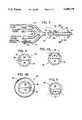
- FIGS. 4, 4A, 4B and 5are transverse sectional views taken along lines 4--4, 4A--4A, 4B--4B, and 5--5 of FIG. 3.
- FIG. 6is a schematic diagram of a portion of the male urinary tract with a schematic prior art combination of bladder irrigating and drain catheter in place.
- FIG. 7is a schematic diagram of the male urinary tract similar to FIG. 6, but with the presently described combination bladder drain and prostate irrigation and drain catheter in place.
- FIG. 8is a fragmentary, schematic view of the herein described catheter component of the assembly in a second embodiment.
- FIG. 9is a fragmentary, longitudinal sectional view taken along the line 9--9 of FIG. 8.
- FIGS. 10, 10A, 11 and 12are transverse sectional views taken along lines 10--10, 10A--10A, 11--11 and 12--12 of FIGS. 8 and 9.
- the urinary tract treating assembly of my inventionis schematically illustrated in FIG. 1. It broadly comprises a catheter, indicated generally at 32; a source 42 of measured quantities of prostate-irrigating fluid under pressure, for example that provided by a gravitationally produced hydrostatic pressure; conduit means 44 interconnecting the catheter and the source; and valve means with associated control means, indicated generally at 46, for transmitting and applying to the prostatic cavity a predetermined amount of irrigating fluid at predetermined time intervals.
- catheter 32The construction and mode of operation of catheter 32 are illustrated in FIGS. 3, 4, 4a, 4b and 5.
- the cathetermay be fabricated by extrusion, molding, dipping or other suitable procedure from a unitary piece of suitable material, preferably medical grade silicone. It has a proximal portion, which lies to the right as viewed in FIG. 3, and a branched distal end, which lies to the left as viewed in that figure.
- proximal portionIn the proximal portion are located one or more bladder drain ports 34, one or more prostate cavity irrigation ports 36, and one or more prostate cavity drain ports 38.
- the branched distal endsare open except for branch 64 which contains balloon (Foley) inflation valve 68, generally a medical Luer lock device.
- balloon (Foley) inflation valve 68generally a medical Luer lock device.
- Three longitudinally arranged conduitsare molded into or mounted longitudinally of the catheter. These have proximal and distal portions corresponding to the proximal and distal portions of the catheter.
- the distal endsare open and outwardly flared to provide lumens for connection to connecting tubing, as will appear hereinafter.
- the first catheter conduit 34, 48is the bladder drain conduit. Urine enters through port 34, drains the length of conduit 48, and is discharged through the open distal end of the latter. It thereupon is transferred by means of tube 50 to a suitable receptacle such as a transparent plastic bladder drain bag 52, FIG. 1, located on the patient's bed.
- a suitable receptaclesuch as a transparent plastic bladder drain bag 52, FIG. 1, located on the patient's bed.
- the second conduit 36, 54functions to discharge prostate-irrigating fluid into prostate cavity 18. Its open distal end is connected via conduit means 44, to a source of irrigating fluid under pressure. This pressure typically is determined by the difference in static elevation of the fluid reservoir 84 and the prostate cavity 18. The fluid travels the length of conduit 54 and is discharged through port 36 into the prostate cavity 18.
- the third catheter conduit 38, 56has for its function draining the spent irrigation fluid and other fluids from the prostate cavity. Its open distal end is connected to a tube 58 which conveys the spent irrigating fluid to a suitable transparent plastic receptacle such as prostate drain bag 60.
- Catheter positioning meansare provided for positioning the catheter in its operative position with urine drain ports 34 positioned in the bladder and with prostate irrigation fluid discharge and drain ports 36, 38 being positioned in surgically-created prostrate cavity 18, as illustrated in FIG. 7.
- the ballooncomprises an expandable segment, indicated in its collapsed condition in full outline at 62. In its expanded condition it is indicated in dashed outline 62.
- Balloon 62is designed to be converted from its collapsed condition to its expanded condition by filling it with sterile water, which thereafter can be drained to restore the balloon to its collapsed, full line condition of FIG. 3.
- a fourth catheter conduit 64which extends the length of the catheter and terminates in one or more openings or ports 66.
- the open distal end of conduit 64is provided with a water-tight device 68 which is generally a conventional Luer lock that can be manually held open to either inflate or deflate the balloon with an appropriate Luer lock actuator, such as a Luer-equipped medical syringe.
- the conduit, and hence balloon 62,can be filled and emptied in this manner.
- FIGS. 8-12An alternate catheter construction is illustrated in FIGS. 8-12, inclusive. It has for its purpose the provision of a drain conduit of enlarged cross section, thus minimizing the possibility of the catheter being clogged by an accumulation of coagulated blood and/or surgically resected debris.
- This purposeis accomplished by combining bladder drain conduit 48 and prostate drain conduit 56 into a single drain conduit 70 of increased cross section and higher flow capacity.
- valve means 72is provided to prevent such access.
- the one way valve means employedis a flattened flap-type valve 72 of resilient tubing.
- This valvehas a contour and construction such that its flattened distal end portion is maintained resiliently closed, while its proximal end portion is maintained fixed in the open condition and attached to the inner wall of catheter 32. Accordingly, urine from the bladder can flow in the downstream direction into enlarged drain conduit 70, where it mixes with the spent irrigation fluid entering the conduit through drain ports 38. The mixture then flows to the open distal end of conduit 70, where it discharges into means for conveying it to a suitable storage receptacle, not illustrated, but common to both both bladder and prostate effluents.
- the open distal end of irrigation fluid conduit 54is connected to a source of irrigation fluid under pressure, delivered in measured amount on a predetermined time schedule.
- a source of irrigation fluid under pressuredelivered in measured amount on a predetermined time schedule. The manner in which this is accomplished is illustrated in FIGS. 1, 1A, 1B and 2.
- the source of irrigation fluid under a hydrostatic head of pressurecomprises a collapsible bag 74 filled with the irrigating fluid and suspended by hook 76 from a conventional "I.V. Pole" 78.
- the collapsible bagdischarges into a flow regulating clamp 80 which is used to regulate the rate of flow of irrigant as it refills reservoir 84 between flushes.
- Combination air vent and check valve 82prevents "air lock" and permits graduated fluid reservoir 84 to empty quickly when pinch valve 88 is opened.
- valve means employed for periodically releasing the measured contents of reservoir 84is illustrated in FIGS. 1, 1A, and 1B.
- Conduit 44 with branch 44ainterconnects the downstream end of calibrated reservoir 84 with the open distal end of catheter conduit 54, which supplies irrigation fluid to the prostatic cavity via discharge port 36.
- An injectable side port 45is provided in branch conduit 44a. This serves the function of permitting medical personnel to syringe-inject antibiotics and other special medication into catheter conduit 44, without disconnecting the conduit.
- Connecting conduit 44includes a length 86 of thin wall resilient tubing made of a resilient plastic such as silicone, or other suitable resilient material.
- Pinch clamp means 88are provided for alternately pinching off and opening the tubing segment in accordance with the desired time sequence.
- the pinch clamp meanscomprises a bracket 90 mounted on control box 91 and having a recess 92 dimensioned to receive the tubing segment.
- the bracketis of reasonably substantial construction and has an abutment wall 93 against which works a spring-pressed, reciprocating ram 94.
- Both manual mechanical and automated electronic meansare provided for reciprocating the ram between its positions of valve opening and valve closing.
- the manual mechanical means employed for this purposecomprises a simple lever 96 fixed to the head of the ram.
- the leverBy means of the lever, the ram can be retracted to open the valve, but against the tension of its associated spring. Upon release of the lever, the spring acts to close the valve.
- the automated electronic means for operating the ramcomprises an electrically operated "pull" solenoid 98, arranged as shown in FIGS. 1A and 1B to open the valve against the compression of the valve spring. The latter member then returns the valve to its closed position upon deenergization of the solenoid. This shuts off the flow of irrigant.
- FIG. 2A simple circuit for operation of the solenoid is illustrated in FIG. 2.
- the electric circuit 100(preferably 12 VDC for patient safety), includes in series circuit relationship solenoid 98 and a adjustable, timed, on-off switch 102 for the operation of the same. If desired, in a shunt circuit 106 there may also be included a manual electric switch 104. This serves the same purpose as lever arm 96 on spring pressed ram 94, in permitting a single operation of the valve when electrically actuated.
- a water sensitive, normally "on”, "on-off” switch 110is provided in branch conduit 44a.
- This switchis in series in circuit 100 with switch 102. If aqueous irrigant such as normal saline solution enters switch 110, the solenoid circuit immediately is interrupted. This closes pinch valve 88, and arrests the further flow of irrigant. Simultaneously, it turns on a flashing indicator light and an audible alarm buzzer (not depicted) to alert the patient and/or medical personnel that a catheter blockage has occurred. Upon clearing the blockage, the light and audible alarm turn off and normal periodic flow of the irrigant is again restored automatically.
- control box 91which also mounts pinch clamp valve 88.
- numerals 112, 114indicate, respectively, the time interval and flow duration control knobs for adjustable, timed "on-off" switch 102.
- the numeral 105indicates the control knob for manual switch 104.
- Drip-regulating clamp 80is opened and reservoir 84 permitted to fill.
- valve 88is actuated either manually or electronically. Thereupon the charge of irrigation fluid flows through conduit 44 and into catheter conduit 54. The flow exits the latter conduit via irrigation port 36. It flushes out the surgically created prostate cavity 18 with a rush of fluid, thereby cleaning it effectively. The spent irrigation fluid exits via drain port 38 in prostate drain conduit 56. From there it flows into prostate drain bag 60 for examination and disposal.
- FIGS. 8-12The operation is similar when the consolidated catheter embodiment of FIGS. 8-12 is employed. However in this case, the urine and spent irrigation fluid exit the catheter via a common conduit 70.
- the urine, entering the catheter through drain port 34passes through one way valve 72 and thence into downstream conduit 70.
- the irrigation fluidenters prostate cavity 18 through port 36, and discharges through ports 38 into common conduit 70.
- clamp 80 and valve 88may be left in their open positions and a drip of controlled rate initiated by regulating valve 80.
- Reservoir 84then serves as drip chamber to confirm visually the selected drip rate.
- Antibiotics or other medicinal substancesmay be introduced as desirable or necessary through side port 45 in conduit 44a.
- the assemblythus may be operated automatically over long operating periods.
- water-sensitive switch 110will terminate the flow of irrigant. The patent's comfort and safety thus are assured.
Landscapes
- Health & Medical Sciences (AREA)
- Life Sciences & Earth Sciences (AREA)
- Heart & Thoracic Surgery (AREA)
- Animal Behavior & Ethology (AREA)
- Engineering & Computer Science (AREA)
- Biomedical Technology (AREA)
- Veterinary Medicine (AREA)
- Public Health (AREA)
- General Health & Medical Sciences (AREA)
- Urology & Nephrology (AREA)
- Vascular Medicine (AREA)
- Cardiology (AREA)
- Transplantation (AREA)
- Oral & Maxillofacial Surgery (AREA)
- Biophysics (AREA)
- Pulmonology (AREA)
- Anesthesiology (AREA)
- Hematology (AREA)
- Child & Adolescent Psychology (AREA)
- Epidemiology (AREA)
- External Artificial Organs (AREA)
Abstract
Description
Claims (15)
Priority Applications (3)
| Application Number | Priority Date | Filing Date | Title |
|---|---|---|---|
| US08/500,473US5688239A (en) | 1995-07-10 | 1995-07-10 | Urinary tract treating assembly with prostate flushing |
| US08/906,721US6102888A (en) | 1995-07-10 | 1997-08-05 | Method of irrigating and draining urinary tract |
| US08/969,396US6183437B1 (en) | 1995-07-10 | 1997-11-13 | Electronic control unit and tubing assembly system for automatically controlling urinary irrigation |
Applications Claiming Priority (1)
| Application Number | Priority Date | Filing Date | Title |
|---|---|---|---|
| US08/500,473US5688239A (en) | 1995-07-10 | 1995-07-10 | Urinary tract treating assembly with prostate flushing |
Related Child Applications (2)
| Application Number | Title | Priority Date | Filing Date |
|---|---|---|---|
| US08/906,721DivisionUS6102888A (en) | 1995-07-10 | 1997-08-05 | Method of irrigating and draining urinary tract |
| US08/969,396Continuation-In-PartUS6183437B1 (en) | 1995-07-10 | 1997-11-13 | Electronic control unit and tubing assembly system for automatically controlling urinary irrigation |
Publications (1)
| Publication Number | Publication Date |
|---|---|
| US5688239Atrue US5688239A (en) | 1997-11-18 |
Family
ID=23989563
Family Applications (2)
| Application Number | Title | Priority Date | Filing Date |
|---|---|---|---|
| US08/500,473Expired - Fee RelatedUS5688239A (en) | 1995-07-10 | 1995-07-10 | Urinary tract treating assembly with prostate flushing |
| US08/906,721Expired - Fee RelatedUS6102888A (en) | 1995-07-10 | 1997-08-05 | Method of irrigating and draining urinary tract |
Family Applications After (1)
| Application Number | Title | Priority Date | Filing Date |
|---|---|---|---|
| US08/906,721Expired - Fee RelatedUS6102888A (en) | 1995-07-10 | 1997-08-05 | Method of irrigating and draining urinary tract |
Country Status (1)
| Country | Link |
|---|---|
| US (2) | US5688239A (en) |
Cited By (61)
| Publication number | Priority date | Publication date | Assignee | Title |
|---|---|---|---|---|
| US5785686A (en)* | 1996-05-02 | 1998-07-28 | Runge; Thomas M. | Cannula system for a biventricular cardiac support system or a cardiopulmonary bypass system |
| US6090069A (en)* | 1997-08-05 | 2000-07-18 | Walker; Frank J. | Irrigation and drainage urinary catheter |
| US6203517B1 (en)* | 1998-06-04 | 2001-03-20 | John I. Shipp | Minimization of transport of cancer cells |
| WO2001083018A1 (en)* | 2000-05-04 | 2001-11-08 | University Of Brighton | Fluid delivery device |
| US20030023144A1 (en)* | 2001-06-29 | 2003-01-30 | Tracey Michael R. | System and method for assessing urinary function |
| WO2003033045A3 (en)* | 2001-10-17 | 2003-08-14 | Argomed Ltd | Catheters with suction capability and related methods and systems for obtaining biosamples in vivo |
| US20030184189A1 (en)* | 2002-03-29 | 2003-10-02 | Sinclair Michael J. | Electrostatic bimorph actuator |
| US20040172009A1 (en)* | 2003-02-27 | 2004-09-02 | Marisi Margaret Grahn | Urinary catheter with check valve |
| US20040171979A1 (en)* | 2002-10-15 | 2004-09-02 | Go Medical Industries Pty, Ltd. | Catheter system and method for delivering medication to the bladder |
| US20050020976A1 (en)* | 2003-06-18 | 2005-01-27 | Terumo Kabushiki Kaisha | Medical therapeutic apparatus |
| US20050054994A1 (en)* | 2002-09-25 | 2005-03-10 | Iulian Cioanta | Catheters with suction capability and related methods and systems for obtaining biosamples in vivo |
| US7004899B2 (en) | 2001-06-29 | 2006-02-28 | Ethicon, Inc. | System and method for assessing urinary function |
| US20060129136A1 (en)* | 2004-12-09 | 2006-06-15 | Meacham George B K | Catheter |
| US7151627B2 (en) | 2000-10-31 | 2006-12-19 | Microsoft Corporation | Microelectrical mechanical structure (MEMS) optical modulator and optical display system |
| US20090099520A1 (en)* | 2005-06-30 | 2009-04-16 | Intuitive Surgical Inc. | Methods of fluid flow control with robotic surgical instruments for irrigation, aspiration, and blowing |
| US7613491B2 (en) | 2002-05-22 | 2009-11-03 | Dexcom, Inc. | Silicone based membranes for use in implantable glucose sensors |
| US7615007B2 (en) | 2006-10-04 | 2009-11-10 | Dexcom, Inc. | Analyte sensor |
| US7640048B2 (en) | 2004-07-13 | 2009-12-29 | Dexcom, Inc. | Analyte sensor |
| US7783333B2 (en) | 2004-07-13 | 2010-08-24 | Dexcom, Inc. | Transcutaneous medical device with variable stiffness |
| US7885697B2 (en) | 2004-07-13 | 2011-02-08 | Dexcom, Inc. | Transcutaneous analyte sensor |
| US20110238042A1 (en)* | 2007-10-02 | 2011-09-29 | C. R. Bard, Inc. | Drainage Catheter with One-Way Valve |
| US8275438B2 (en) | 2006-10-04 | 2012-09-25 | Dexcom, Inc. | Analyte sensor |
| US8287453B2 (en) | 2003-12-05 | 2012-10-16 | Dexcom, Inc. | Analyte sensor |
| US8290559B2 (en) | 2007-12-17 | 2012-10-16 | Dexcom, Inc. | Systems and methods for processing sensor data |
| US8298142B2 (en) | 2006-10-04 | 2012-10-30 | Dexcom, Inc. | Analyte sensor |
| US8364231B2 (en) | 2006-10-04 | 2013-01-29 | Dexcom, Inc. | Analyte sensor |
| US8364230B2 (en) | 2006-10-04 | 2013-01-29 | Dexcom, Inc. | Analyte sensor |
| US8364229B2 (en) | 2003-07-25 | 2013-01-29 | Dexcom, Inc. | Analyte sensors having a signal-to-noise ratio substantially unaffected by non-constant noise |
| US8396528B2 (en) | 2008-03-25 | 2013-03-12 | Dexcom, Inc. | Analyte sensor |
| US8417312B2 (en) | 2007-10-25 | 2013-04-09 | Dexcom, Inc. | Systems and methods for processing sensor data |
| US8425417B2 (en) | 2003-12-05 | 2013-04-23 | Dexcom, Inc. | Integrated device for continuous in vivo analyte detection and simultaneous control of an infusion device |
| US8425416B2 (en) | 2006-10-04 | 2013-04-23 | Dexcom, Inc. | Analyte sensor |
| US8447376B2 (en) | 2006-10-04 | 2013-05-21 | Dexcom, Inc. | Analyte sensor |
| US8449464B2 (en) | 2006-10-04 | 2013-05-28 | Dexcom, Inc. | Analyte sensor |
| US8478377B2 (en) | 2006-10-04 | 2013-07-02 | Dexcom, Inc. | Analyte sensor |
| US8562528B2 (en) | 2006-10-04 | 2013-10-22 | Dexcom, Inc. | Analyte sensor |
| US8562558B2 (en) | 2007-06-08 | 2013-10-22 | Dexcom, Inc. | Integrated medicament delivery device for use with continuous analyte sensor |
| US8626257B2 (en) | 2003-08-01 | 2014-01-07 | Dexcom, Inc. | Analyte sensor |
| US8886273B2 (en) | 2003-08-01 | 2014-11-11 | Dexcom, Inc. | Analyte sensor |
| US9135402B2 (en) | 2007-12-17 | 2015-09-15 | Dexcom, Inc. | Systems and methods for processing sensor data |
| CN106512185A (en)* | 2016-10-27 | 2017-03-22 | 南方医科大学南方医院 | Craniocerebral drainage tube |
| US9763609B2 (en) | 2003-07-25 | 2017-09-19 | Dexcom, Inc. | Analyte sensors having a signal-to-noise ratio substantially unaffected by non-constant noise |
| US9986942B2 (en) | 2004-07-13 | 2018-06-05 | Dexcom, Inc. | Analyte sensor |
| US20200085378A1 (en)* | 2014-09-28 | 2020-03-19 | Potrero Medical, Inc. | Systems, devices and methods for sensing physiologic data and draining and analyzing bodily fluids |
| US10610137B2 (en) | 2005-03-10 | 2020-04-07 | Dexcom, Inc. | System and methods for processing analyte sensor data for sensor calibration |
| US10668246B2 (en) | 2015-02-20 | 2020-06-02 | Portela Soni Medical, Inc. | Urinary catheter, kit and method |
| US10791928B2 (en) | 2007-05-18 | 2020-10-06 | Dexcom, Inc. | Analyte sensors having a signal-to-noise ratio substantially unaffected by non-constant noise |
| US10813577B2 (en) | 2005-06-21 | 2020-10-27 | Dexcom, Inc. | Analyte sensor |
| US10835672B2 (en) | 2004-02-26 | 2020-11-17 | Dexcom, Inc. | Integrated insulin delivery system with continuous glucose sensor |
| US10966609B2 (en) | 2004-02-26 | 2021-04-06 | Dexcom, Inc. | Integrated medicament delivery device for use with continuous analyte sensor |
| US10980461B2 (en) | 2008-11-07 | 2021-04-20 | Dexcom, Inc. | Advanced analyte sensor calibration and error detection |
| US11000215B1 (en) | 2003-12-05 | 2021-05-11 | Dexcom, Inc. | Analyte sensor |
| CN112972865A (en)* | 2021-02-03 | 2021-06-18 | 川北医学院 | Urethral catheterization device used in urinary surgery |
| US20210330933A1 (en)* | 2020-04-23 | 2021-10-28 | Covidien Lp | Catheter with valves |
| CN114007503A (en)* | 2019-06-26 | 2022-02-01 | 科洛普拉斯特公司 | Catheter including combination valve and sensor |
| US11246990B2 (en) | 2004-02-26 | 2022-02-15 | Dexcom, Inc. | Integrated delivery device for continuous glucose sensor |
| US11331022B2 (en) | 2017-10-24 | 2022-05-17 | Dexcom, Inc. | Pre-connected analyte sensors |
| US11350862B2 (en) | 2017-10-24 | 2022-06-07 | Dexcom, Inc. | Pre-connected analyte sensors |
| US11399745B2 (en) | 2006-10-04 | 2022-08-02 | Dexcom, Inc. | Dual electrode system for a continuous analyte sensor |
| US11633133B2 (en) | 2003-12-05 | 2023-04-25 | Dexcom, Inc. | Dual electrode system for a continuous analyte sensor |
| US20240198040A1 (en)* | 2022-02-16 | 2024-06-20 | Ezurotech Co., Ltd. | Liquid medication-injecting urinary catheter |
Families Citing this family (15)
| Publication number | Priority date | Publication date | Assignee | Title |
|---|---|---|---|---|
| AUPQ115499A0 (en)* | 1999-06-24 | 1999-07-15 | Colocare Holdings Pty Limited | Colostomy pump device |
| US6793651B1 (en)* | 2000-02-23 | 2004-09-21 | Icu Medical, Inc. | Urinary catheter system with a releasable connector |
| US7485150B2 (en)* | 2002-04-23 | 2009-02-03 | Boston Scientific Scimed, Inc. | Drainage devices and methods |
| US7112177B2 (en)* | 2003-03-04 | 2006-09-26 | Wolfe Tory Medical, Inc. | Apparatus for monitoring intra-abdominal pressure |
| US20070255167A1 (en)* | 2004-03-01 | 2007-11-01 | Wolfe Tory Medical, Inc. | Apparatus for monitoring intra-abdominal pressure |
| US7644722B2 (en)* | 2003-03-04 | 2010-01-12 | Wolfe Tory Medical, Inc. | Medical valve and method to monitor intra-abdominal pressure |
| AU2003901057A0 (en)* | 2003-03-10 | 2003-03-20 | Zsolt Balosh | Intra-abdominal urinary catheter pressure monitor |
| EP1804648A4 (en)* | 2004-10-11 | 2009-07-15 | Wolfe Tory Medical Inc | Intra-abdominal pressure monitoring device and method |
| JP2009523463A (en)* | 2004-12-03 | 2009-06-25 | ウォルフ トーリー メディカル インコーポレーティッド | Urinary catheter for continuous intraperitoneal pressure monitoring optionally equipped with a deep body temperature sensor |
| US7396366B2 (en)* | 2005-05-11 | 2008-07-08 | Boston Scientific Scimed, Inc. | Ureteral stent with conforming retention structure |
| WO2007103809A2 (en)* | 2006-03-03 | 2007-09-13 | Garcia Maurice M | System and method for urinary tract cell collection, diagnosis, and chemotherapy |
| US20090171241A1 (en)* | 2006-03-03 | 2009-07-02 | Garcia Maurice M | System and method for urinary tract cell collection, diagnosis, and chemotherapy |
| CN102727955A (en)* | 2012-07-26 | 2012-10-17 | 东南大学 | Full-automatic bladder irrigation device |
| WO2014043650A2 (en)* | 2012-09-17 | 2014-03-20 | Theranova, Llc | Systems, devices and methods for urine monitoring |
| CN104069580A (en)* | 2014-07-14 | 2014-10-01 | 郑州大学第一附属医院 | Intelligent urinary catheterization device |
Citations (13)
| Publication number | Priority date | Publication date | Assignee | Title |
|---|---|---|---|---|
| US3902492A (en)* | 1973-05-14 | 1975-09-02 | Roger Malcolm Greenhalgh | Catheter |
| US4211233A (en)* | 1978-01-05 | 1980-07-08 | Lin Edward D | Urethral catheter |
| US4262668A (en)* | 1979-04-06 | 1981-04-21 | Baxter Travenol Laboratories, Inc. | Fixed volume infusion device |
| DE3306342A1 (en)* | 1982-01-28 | 1984-08-23 | Hans E. Prof. Dr.med. 8500 Nürnberg Sachse | Catheter |
| US4579554A (en)* | 1984-01-30 | 1986-04-01 | Glassman Jacob A | Indwelling urinary catheter |
| GB2169206A (en)* | 1985-01-04 | 1986-07-09 | Glassman Jacob A | Catheters |
| WO1988001183A1 (en)* | 1986-08-20 | 1988-02-25 | Ingvar Andersson | Arrangement for the instillation of fluids in a urethra |
| WO1989003232A1 (en)* | 1987-10-09 | 1989-04-20 | Bukh Meditec A/S | A medical device for introduction into a body cavity |
| US5007897A (en)* | 1989-05-30 | 1991-04-16 | Kalb Irvin M | Drug delivery catheter |
| EP0449472A1 (en)* | 1990-03-22 | 1991-10-02 | Argomed Ltd | An apparatus for localized thermal treatment of mammals |
| WO1992018199A1 (en)* | 1989-06-16 | 1992-10-29 | Mmtc, Inc. | Catheters for treating prostate disease |
| WO1993004727A1 (en)* | 1991-08-30 | 1993-03-18 | American Medical Systems | Balloon-catheter |
| US5306241A (en)* | 1990-08-16 | 1994-04-26 | Samples Charles R | Method of catheterization on and bladder drainage |
- 1995
- 1995-07-10USUS08/500,473patent/US5688239A/ennot_activeExpired - Fee Related
- 1997
- 1997-08-05USUS08/906,721patent/US6102888A/ennot_activeExpired - Fee Related
Patent Citations (13)
| Publication number | Priority date | Publication date | Assignee | Title |
|---|---|---|---|---|
| US3902492A (en)* | 1973-05-14 | 1975-09-02 | Roger Malcolm Greenhalgh | Catheter |
| US4211233A (en)* | 1978-01-05 | 1980-07-08 | Lin Edward D | Urethral catheter |
| US4262668A (en)* | 1979-04-06 | 1981-04-21 | Baxter Travenol Laboratories, Inc. | Fixed volume infusion device |
| DE3306342A1 (en)* | 1982-01-28 | 1984-08-23 | Hans E. Prof. Dr.med. 8500 Nürnberg Sachse | Catheter |
| US4579554A (en)* | 1984-01-30 | 1986-04-01 | Glassman Jacob A | Indwelling urinary catheter |
| GB2169206A (en)* | 1985-01-04 | 1986-07-09 | Glassman Jacob A | Catheters |
| WO1988001183A1 (en)* | 1986-08-20 | 1988-02-25 | Ingvar Andersson | Arrangement for the instillation of fluids in a urethra |
| WO1989003232A1 (en)* | 1987-10-09 | 1989-04-20 | Bukh Meditec A/S | A medical device for introduction into a body cavity |
| US5007897A (en)* | 1989-05-30 | 1991-04-16 | Kalb Irvin M | Drug delivery catheter |
| WO1992018199A1 (en)* | 1989-06-16 | 1992-10-29 | Mmtc, Inc. | Catheters for treating prostate disease |
| EP0449472A1 (en)* | 1990-03-22 | 1991-10-02 | Argomed Ltd | An apparatus for localized thermal treatment of mammals |
| US5306241A (en)* | 1990-08-16 | 1994-04-26 | Samples Charles R | Method of catheterization on and bladder drainage |
| WO1993004727A1 (en)* | 1991-08-30 | 1993-03-18 | American Medical Systems | Balloon-catheter |
Cited By (171)
| Publication number | Priority date | Publication date | Assignee | Title |
|---|---|---|---|---|
| US5785686A (en)* | 1996-05-02 | 1998-07-28 | Runge; Thomas M. | Cannula system for a biventricular cardiac support system or a cardiopulmonary bypass system |
| US6090069A (en)* | 1997-08-05 | 2000-07-18 | Walker; Frank J. | Irrigation and drainage urinary catheter |
| US6203517B1 (en)* | 1998-06-04 | 2001-03-20 | John I. Shipp | Minimization of transport of cancer cells |
| WO2001083018A1 (en)* | 2000-05-04 | 2001-11-08 | University Of Brighton | Fluid delivery device |
| US7151627B2 (en) | 2000-10-31 | 2006-12-19 | Microsoft Corporation | Microelectrical mechanical structure (MEMS) optical modulator and optical display system |
| US20040133067A1 (en)* | 2001-06-29 | 2004-07-08 | Tracey Michael R. | System and method for assessing detrusor instability |
| US7252631B2 (en) | 2001-06-29 | 2007-08-07 | Ethicon, Inc. | System and method for assessing detrusor instability |
| US20030027326A1 (en)* | 2001-06-29 | 2003-02-06 | Ulf Ulmsten | System and method for assessing urinary function |
| US7056288B2 (en) | 2001-06-29 | 2006-06-06 | Ethicon Inc. | System and method for assessing urinary function |
| US7004899B2 (en) | 2001-06-29 | 2006-02-28 | Ethicon, Inc. | System and method for assessing urinary function |
| US20030028074A1 (en)* | 2001-06-29 | 2003-02-06 | Tracey Michael R. | System and method for assessing urinary function |
| US20030023144A1 (en)* | 2001-06-29 | 2003-01-30 | Tracey Michael R. | System and method for assessing urinary function |
| US7255673B2 (en) | 2001-06-29 | 2007-08-14 | Ethicon, Inc. | System and method for assessing urinary function |
| US6997884B2 (en) | 2001-06-29 | 2006-02-14 | Ethicon, Inc. | System and method for assessing urinary function |
| US20030028159A1 (en)* | 2001-06-29 | 2003-02-06 | Tracey Michael R. | System and method for assessing urinary function |
| US6916283B2 (en) | 2001-06-29 | 2005-07-12 | Ethicon, Inc. | System and method for assessing urinary function |
| US6896650B2 (en)* | 2001-06-29 | 2005-05-24 | Ethicon Inc. | System and method for assessing urinary function |
| WO2003033045A3 (en)* | 2001-10-17 | 2003-08-14 | Argomed Ltd | Catheters with suction capability and related methods and systems for obtaining biosamples in vivo |
| US7249856B2 (en) | 2002-03-29 | 2007-07-31 | Microsoft Corporation | Electrostatic bimorph actuator |
| US20040227428A1 (en)* | 2002-03-29 | 2004-11-18 | Microsoft Corporation | Electrostatic bimorph actuator |
| US20030184189A1 (en)* | 2002-03-29 | 2003-10-02 | Sinclair Michael J. | Electrostatic bimorph actuator |
| US7053519B2 (en) | 2002-03-29 | 2006-05-30 | Microsoft Corporation | Electrostatic bimorph actuator |
| US8064977B2 (en) | 2002-05-22 | 2011-11-22 | Dexcom, Inc. | Silicone based membranes for use in implantable glucose sensors |
| US11020026B2 (en) | 2002-05-22 | 2021-06-01 | Dexcom, Inc. | Silicone based membranes for use in implantable glucose sensors |
| US9549693B2 (en) | 2002-05-22 | 2017-01-24 | Dexcom, Inc. | Silicone based membranes for use in implantable glucose sensors |
| US10052051B2 (en) | 2002-05-22 | 2018-08-21 | Dexcom, Inc. | Silicone based membranes for use in implantable glucose sensors |
| US8543184B2 (en) | 2002-05-22 | 2013-09-24 | Dexcom, Inc. | Silicone based membranes for use in implantable glucose sensors |
| US7613491B2 (en) | 2002-05-22 | 2009-11-03 | Dexcom, Inc. | Silicone based membranes for use in implantable glucose sensors |
| US20050054994A1 (en)* | 2002-09-25 | 2005-03-10 | Iulian Cioanta | Catheters with suction capability and related methods and systems for obtaining biosamples in vivo |
| US20040171979A1 (en)* | 2002-10-15 | 2004-09-02 | Go Medical Industries Pty, Ltd. | Catheter system and method for delivering medication to the bladder |
| US7150739B2 (en) | 2002-10-15 | 2006-12-19 | Go Medical Industries Pty, Ltd. | Catheter system and method for delivering medication to the bladder |
| US7331949B2 (en)* | 2003-02-27 | 2008-02-19 | Margaret Grahn Marisi | Urinary catheter with check valve |
| US20080125758A1 (en)* | 2003-02-27 | 2008-05-29 | Margaret Grahn Marisi | Urinary catheter with check valve |
| US20040172009A1 (en)* | 2003-02-27 | 2004-09-02 | Marisi Margaret Grahn | Urinary catheter with check valve |
| US7399290B2 (en)* | 2003-06-18 | 2008-07-15 | Terumo Kabushiki Kaisha | Medical therapeutic apparatus |
| US20050020976A1 (en)* | 2003-06-18 | 2005-01-27 | Terumo Kabushiki Kaisha | Medical therapeutic apparatus |
| US10376143B2 (en) | 2003-07-25 | 2019-08-13 | Dexcom, Inc. | Analyte sensors having a signal-to-noise ratio substantially unaffected by non-constant noise |
| US8364229B2 (en) | 2003-07-25 | 2013-01-29 | Dexcom, Inc. | Analyte sensors having a signal-to-noise ratio substantially unaffected by non-constant noise |
| US9763609B2 (en) | 2003-07-25 | 2017-09-19 | Dexcom, Inc. | Analyte sensors having a signal-to-noise ratio substantially unaffected by non-constant noise |
| US8626257B2 (en) | 2003-08-01 | 2014-01-07 | Dexcom, Inc. | Analyte sensor |
| US8886273B2 (en) | 2003-08-01 | 2014-11-11 | Dexcom, Inc. | Analyte sensor |
| US10052055B2 (en) | 2003-08-01 | 2018-08-21 | Dexcom, Inc. | Analyte sensor |
| US8287453B2 (en) | 2003-12-05 | 2012-10-16 | Dexcom, Inc. | Analyte sensor |
| US11000215B1 (en) | 2003-12-05 | 2021-05-11 | Dexcom, Inc. | Analyte sensor |
| US11633133B2 (en) | 2003-12-05 | 2023-04-25 | Dexcom, Inc. | Dual electrode system for a continuous analyte sensor |
| US8425417B2 (en) | 2003-12-05 | 2013-04-23 | Dexcom, Inc. | Integrated device for continuous in vivo analyte detection and simultaneous control of an infusion device |
| US11020031B1 (en) | 2003-12-05 | 2021-06-01 | Dexcom, Inc. | Analyte sensor |
| US11246990B2 (en) | 2004-02-26 | 2022-02-15 | Dexcom, Inc. | Integrated delivery device for continuous glucose sensor |
| US10835672B2 (en) | 2004-02-26 | 2020-11-17 | Dexcom, Inc. | Integrated insulin delivery system with continuous glucose sensor |
| US10966609B2 (en) | 2004-02-26 | 2021-04-06 | Dexcom, Inc. | Integrated medicament delivery device for use with continuous analyte sensor |
| US12115357B2 (en) | 2004-02-26 | 2024-10-15 | Dexcom, Inc. | Integrated delivery device for continuous glucose sensor |
| US12102410B2 (en) | 2004-02-26 | 2024-10-01 | Dexcom, Inc | Integrated medicament delivery device for use with continuous analyte sensor |
| US12226617B2 (en) | 2004-02-26 | 2025-02-18 | Dexcom, Inc. | Integrated delivery device for continuous glucose sensor |
| US10993641B2 (en) | 2004-07-13 | 2021-05-04 | Dexcom, Inc. | Analyte sensor |
| US10524703B2 (en) | 2004-07-13 | 2020-01-07 | Dexcom, Inc. | Transcutaneous analyte sensor |
| US10722152B2 (en) | 2004-07-13 | 2020-07-28 | Dexcom, Inc. | Analyte sensor |
| US10709363B2 (en) | 2004-07-13 | 2020-07-14 | Dexcom, Inc. | Analyte sensor |
| US11883164B2 (en) | 2004-07-13 | 2024-01-30 | Dexcom, Inc. | System and methods for processing analyte sensor data for sensor calibration |
| US7640048B2 (en) | 2004-07-13 | 2009-12-29 | Dexcom, Inc. | Analyte sensor |
| US10709362B2 (en) | 2004-07-13 | 2020-07-14 | Dexcom, Inc. | Analyte sensor |
| US11064917B2 (en) | 2004-07-13 | 2021-07-20 | Dexcom, Inc. | Analyte sensor |
| US8750955B2 (en) | 2004-07-13 | 2014-06-10 | Dexcom, Inc. | Analyte sensor |
| US10799159B2 (en) | 2004-07-13 | 2020-10-13 | Dexcom, Inc. | Analyte sensor |
| US8792953B2 (en) | 2004-07-13 | 2014-07-29 | Dexcom, Inc. | Transcutaneous analyte sensor |
| US8812072B2 (en) | 2004-07-13 | 2014-08-19 | Dexcom, Inc. | Transcutaneous medical device with variable stiffness |
| US11045120B2 (en) | 2004-07-13 | 2021-06-29 | Dexcom, Inc. | Analyte sensor |
| US11026605B1 (en) | 2004-07-13 | 2021-06-08 | Dexcom, Inc. | Analyte sensor |
| US7783333B2 (en) | 2004-07-13 | 2010-08-24 | Dexcom, Inc. | Transcutaneous medical device with variable stiffness |
| US7857760B2 (en) | 2004-07-13 | 2010-12-28 | Dexcom, Inc. | Analyte sensor |
| US7885697B2 (en) | 2004-07-13 | 2011-02-08 | Dexcom, Inc. | Transcutaneous analyte sensor |
| US10799158B2 (en) | 2004-07-13 | 2020-10-13 | Dexcom, Inc. | Analyte sensor |
| US10813576B2 (en) | 2004-07-13 | 2020-10-27 | Dexcom, Inc. | Analyte sensor |
| US9414777B2 (en) | 2004-07-13 | 2016-08-16 | Dexcom, Inc. | Transcutaneous analyte sensor |
| US10827956B2 (en) | 2004-07-13 | 2020-11-10 | Dexcom, Inc. | Analyte sensor |
| US10993642B2 (en) | 2004-07-13 | 2021-05-04 | Dexcom, Inc. | Analyte sensor |
| US10980452B2 (en) | 2004-07-13 | 2021-04-20 | Dexcom, Inc. | Analyte sensor |
| US10918314B2 (en) | 2004-07-13 | 2021-02-16 | Dexcom, Inc. | Analyte sensor |
| US10932700B2 (en) | 2004-07-13 | 2021-03-02 | Dexcom, Inc. | Analyte sensor |
| US10918315B2 (en) | 2004-07-13 | 2021-02-16 | Dexcom, Inc. | Analyte sensor |
| US9986942B2 (en) | 2004-07-13 | 2018-06-05 | Dexcom, Inc. | Analyte sensor |
| US10918313B2 (en) | 2004-07-13 | 2021-02-16 | Dexcom, Inc. | Analyte sensor |
| US20060129136A1 (en)* | 2004-12-09 | 2006-06-15 | Meacham George B K | Catheter |
| US10743801B2 (en) | 2005-03-10 | 2020-08-18 | Dexcom, Inc. | System and methods for processing analyte sensor data for sensor calibration |
| US10716498B2 (en) | 2005-03-10 | 2020-07-21 | Dexcom, Inc. | System and methods for processing analyte sensor data for sensor calibration |
| US10925524B2 (en) | 2005-03-10 | 2021-02-23 | Dexcom, Inc. | System and methods for processing analyte sensor data for sensor calibration |
| US10918318B2 (en) | 2005-03-10 | 2021-02-16 | Dexcom, Inc. | System and methods for processing analyte sensor data for sensor calibration |
| US10898114B2 (en) | 2005-03-10 | 2021-01-26 | Dexcom, Inc. | System and methods for processing analyte sensor data for sensor calibration |
| US10856787B2 (en) | 2005-03-10 | 2020-12-08 | Dexcom, Inc. | System and methods for processing analyte sensor data for sensor calibration |
| US10617336B2 (en) | 2005-03-10 | 2020-04-14 | Dexcom, Inc. | System and methods for processing analyte sensor data for sensor calibration |
| US11051726B2 (en) | 2005-03-10 | 2021-07-06 | Dexcom, Inc. | System and methods for processing analyte sensor data for sensor calibration |
| US11000213B2 (en) | 2005-03-10 | 2021-05-11 | Dexcom, Inc. | System and methods for processing analyte sensor data for sensor calibration |
| US10610137B2 (en) | 2005-03-10 | 2020-04-07 | Dexcom, Inc. | System and methods for processing analyte sensor data for sensor calibration |
| US10918316B2 (en) | 2005-03-10 | 2021-02-16 | Dexcom, Inc. | System and methods for processing analyte sensor data for sensor calibration |
| US10709364B2 (en) | 2005-03-10 | 2020-07-14 | Dexcom, Inc. | System and methods for processing analyte sensor data for sensor calibration |
| US10918317B2 (en) | 2005-03-10 | 2021-02-16 | Dexcom, Inc. | System and methods for processing analyte sensor data for sensor calibration |
| US10610135B2 (en) | 2005-03-10 | 2020-04-07 | Dexcom, Inc. | System and methods for processing analyte sensor data for sensor calibration |
| US10610136B2 (en) | 2005-03-10 | 2020-04-07 | Dexcom, Inc. | System and methods for processing analyte sensor data for sensor calibration |
| US10813577B2 (en) | 2005-06-21 | 2020-10-27 | Dexcom, Inc. | Analyte sensor |
| US9446177B2 (en) | 2005-06-30 | 2016-09-20 | Intuitive Surgical Operations, Inc. | Surgical instrument with robotic and manual actuation features |
| US11517379B2 (en) | 2005-06-30 | 2022-12-06 | Intuitive Surgical Operations, Inc. | Surgical instrument with robotic and manual actuation features |
| US20090099520A1 (en)* | 2005-06-30 | 2009-04-16 | Intuitive Surgical Inc. | Methods of fluid flow control with robotic surgical instruments for irrigation, aspiration, and blowing |
| US9216243B2 (en)* | 2005-06-30 | 2015-12-22 | Intuitive Surgical Operations, Inc. | Robotic surgical systems with fluid flow control for irrigation, aspiration, and blowing |
| US10441370B2 (en) | 2005-06-30 | 2019-10-15 | Intuitive Surgical Operations, Inc. | Surgical instrument with robotic and manual actuation features |
| US20120197182A1 (en)* | 2005-06-30 | 2012-08-02 | Intuitive Surgical, Inc. | Robotic Surgical Systems With Fluid Flow Control For Irrigation, Aspiration, and Blowing |
| US8275438B2 (en) | 2006-10-04 | 2012-09-25 | Dexcom, Inc. | Analyte sensor |
| US8364231B2 (en) | 2006-10-04 | 2013-01-29 | Dexcom, Inc. | Analyte sensor |
| US8774886B2 (en) | 2006-10-04 | 2014-07-08 | Dexcom, Inc. | Analyte sensor |
| US8425416B2 (en) | 2006-10-04 | 2013-04-23 | Dexcom, Inc. | Analyte sensor |
| US8478377B2 (en) | 2006-10-04 | 2013-07-02 | Dexcom, Inc. | Analyte sensor |
| US8532730B2 (en) | 2006-10-04 | 2013-09-10 | Dexcom, Inc. | Analyte sensor |
| US9451908B2 (en) | 2006-10-04 | 2016-09-27 | Dexcom, Inc. | Analyte sensor |
| US7615007B2 (en) | 2006-10-04 | 2009-11-10 | Dexcom, Inc. | Analyte sensor |
| US8449464B2 (en) | 2006-10-04 | 2013-05-28 | Dexcom, Inc. | Analyte sensor |
| US8447376B2 (en) | 2006-10-04 | 2013-05-21 | Dexcom, Inc. | Analyte sensor |
| US10349873B2 (en) | 2006-10-04 | 2019-07-16 | Dexcom, Inc. | Analyte sensor |
| US8562528B2 (en) | 2006-10-04 | 2013-10-22 | Dexcom, Inc. | Analyte sensor |
| US8298142B2 (en) | 2006-10-04 | 2012-10-30 | Dexcom, Inc. | Analyte sensor |
| US8911367B2 (en) | 2006-10-04 | 2014-12-16 | Dexcom, Inc. | Analyte sensor |
| US7775975B2 (en) | 2006-10-04 | 2010-08-17 | Dexcom, Inc. | Analyte sensor |
| US11399745B2 (en) | 2006-10-04 | 2022-08-02 | Dexcom, Inc. | Dual electrode system for a continuous analyte sensor |
| US8364230B2 (en) | 2006-10-04 | 2013-01-29 | Dexcom, Inc. | Analyte sensor |
| US11382539B2 (en) | 2006-10-04 | 2022-07-12 | Dexcom, Inc. | Analyte sensor |
| US10791928B2 (en) | 2007-05-18 | 2020-10-06 | Dexcom, Inc. | Analyte sensors having a signal-to-noise ratio substantially unaffected by non-constant noise |
| US12433485B2 (en) | 2007-05-18 | 2025-10-07 | Dexcom, Inc. | Analyte sensors having a signal-to-noise ratio substantially unaffected by non-constant noise |
| US9741139B2 (en) | 2007-06-08 | 2017-08-22 | Dexcom, Inc. | Integrated medicament delivery device for use with continuous analyte sensor |
| US11373347B2 (en) | 2007-06-08 | 2022-06-28 | Dexcom, Inc. | Integrated medicament delivery device for use with continuous analyte sensor |
| US8562558B2 (en) | 2007-06-08 | 2013-10-22 | Dexcom, Inc. | Integrated medicament delivery device for use with continuous analyte sensor |
| US10403012B2 (en) | 2007-06-08 | 2019-09-03 | Dexcom, Inc. | Integrated medicament delivery device for use with continuous analyte sensor |
| US12394120B2 (en) | 2007-06-08 | 2025-08-19 | Dexcom, Inc. | Integrated medicament delivery device for use with continuous analyte sensor |
| US20110238042A1 (en)* | 2007-10-02 | 2011-09-29 | C. R. Bard, Inc. | Drainage Catheter with One-Way Valve |
| US11160926B1 (en) | 2007-10-09 | 2021-11-02 | Dexcom, Inc. | Pre-connected analyte sensors |
| US11744943B2 (en) | 2007-10-09 | 2023-09-05 | Dexcom, Inc. | Integrated insulin delivery system with continuous glucose sensor |
| US12397113B2 (en) | 2007-10-09 | 2025-08-26 | Dexcom, Inc. | Integrated insulin delivery system with continuous glucose sensor |
| US12397110B2 (en) | 2007-10-09 | 2025-08-26 | Dexcom, Inc. | Integrated insulin delivery system with continuous glucose sensor |
| US12246166B2 (en) | 2007-10-09 | 2025-03-11 | Dexcom, Inc. | Integrated insulin delivery system with continuous glucose sensor |
| US11272869B2 (en) | 2007-10-25 | 2022-03-15 | Dexcom, Inc. | Systems and methods for processing sensor data |
| US8417312B2 (en) | 2007-10-25 | 2013-04-09 | Dexcom, Inc. | Systems and methods for processing sensor data |
| US10182751B2 (en) | 2007-10-25 | 2019-01-22 | Dexcom, Inc. | Systems and methods for processing sensor data |
| US9717449B2 (en) | 2007-10-25 | 2017-08-01 | Dexcom, Inc. | Systems and methods for processing sensor data |
| US11342058B2 (en) | 2007-12-17 | 2022-05-24 | Dexcom, Inc. | Systems and methods for processing sensor data |
| US9901307B2 (en) | 2007-12-17 | 2018-02-27 | Dexcom, Inc. | Systems and methods for processing sensor data |
| US8290559B2 (en) | 2007-12-17 | 2012-10-16 | Dexcom, Inc. | Systems and methods for processing sensor data |
| US9149233B2 (en) | 2007-12-17 | 2015-10-06 | Dexcom, Inc. | Systems and methods for processing sensor data |
| US10827980B2 (en) | 2007-12-17 | 2020-11-10 | Dexcom, Inc. | Systems and methods for processing sensor data |
| US9135402B2 (en) | 2007-12-17 | 2015-09-15 | Dexcom, Inc. | Systems and methods for processing sensor data |
| US12165757B2 (en) | 2007-12-17 | 2024-12-10 | Dexcom, Inc. | Systems and methods for processing sensor data |
| US9339238B2 (en) | 2007-12-17 | 2016-05-17 | Dexcom, Inc. | Systems and methods for processing sensor data |
| US10506982B2 (en) | 2007-12-17 | 2019-12-17 | Dexcom, Inc. | Systems and methods for processing sensor data |
| US9839395B2 (en) | 2007-12-17 | 2017-12-12 | Dexcom, Inc. | Systems and methods for processing sensor data |
| US9149234B2 (en) | 2007-12-17 | 2015-10-06 | Dexcom, Inc. | Systems and methods for processing sensor data |
| US11896374B2 (en) | 2008-03-25 | 2024-02-13 | Dexcom, Inc. | Analyte sensor |
| US8396528B2 (en) | 2008-03-25 | 2013-03-12 | Dexcom, Inc. | Analyte sensor |
| US10602968B2 (en) | 2008-03-25 | 2020-03-31 | Dexcom, Inc. | Analyte sensor |
| US10980461B2 (en) | 2008-11-07 | 2021-04-20 | Dexcom, Inc. | Advanced analyte sensor calibration and error detection |
| US20200085378A1 (en)* | 2014-09-28 | 2020-03-19 | Potrero Medical, Inc. | Systems, devices and methods for sensing physiologic data and draining and analyzing bodily fluids |
| US11672948B2 (en) | 2015-02-20 | 2023-06-13 | Portela Soni Medical, Inc. | Urinary catheter, kit and method |
| US10668246B2 (en) | 2015-02-20 | 2020-06-02 | Portela Soni Medical, Inc. | Urinary catheter, kit and method |
| CN106512185A (en)* | 2016-10-27 | 2017-03-22 | 南方医科大学南方医院 | Craniocerebral drainage tube |
| US11706876B2 (en) | 2017-10-24 | 2023-07-18 | Dexcom, Inc. | Pre-connected analyte sensors |
| US11943876B2 (en) | 2017-10-24 | 2024-03-26 | Dexcom, Inc. | Pre-connected analyte sensors |
| US11382540B2 (en) | 2017-10-24 | 2022-07-12 | Dexcom, Inc. | Pre-connected analyte sensors |
| US12150250B2 (en) | 2017-10-24 | 2024-11-19 | Dexcom, Inc. | Pre-connected analyte sensors |
| US11350862B2 (en) | 2017-10-24 | 2022-06-07 | Dexcom, Inc. | Pre-connected analyte sensors |
| US11331022B2 (en) | 2017-10-24 | 2022-05-17 | Dexcom, Inc. | Pre-connected analyte sensors |
| CN114007503A (en)* | 2019-06-26 | 2022-02-01 | 科洛普拉斯特公司 | Catheter including combination valve and sensor |
| US12042607B2 (en)* | 2020-04-23 | 2024-07-23 | Covidien Lp | Catheter with valves |
| US20210330933A1 (en)* | 2020-04-23 | 2021-10-28 | Covidien Lp | Catheter with valves |
| CN112972865A (en)* | 2021-02-03 | 2021-06-18 | 川北医学院 | Urethral catheterization device used in urinary surgery |
| US12246138B2 (en)* | 2022-02-16 | 2025-03-11 | Ezurotech Co., Ltd. | Liquid medication-injecting urinary catheter |
| EP4480524A4 (en)* | 2022-02-16 | 2025-06-18 | Ezurotech Co., Ltd. | URINARY CATHETER WITH LIQUID MEDICINE INJECTION |
| US20240198040A1 (en)* | 2022-02-16 | 2024-06-20 | Ezurotech Co., Ltd. | Liquid medication-injecting urinary catheter |
Also Published As
| Publication number | Publication date |
|---|---|
| US6102888A (en) | 2000-08-15 |
Similar Documents
| Publication | Publication Date | Title |
|---|---|---|
| US5688239A (en) | Urinary tract treating assembly with prostate flushing | |
| US6090069A (en) | Irrigation and drainage urinary catheter | |
| US6183437B1 (en) | Electronic control unit and tubing assembly system for automatically controlling urinary irrigation | |
| US4723946A (en) | Urinary catheter, hygiene system and process therefor | |
| US5738656A (en) | Drainage apparatus and method of use | |
| US4525156A (en) | Method for stomach lavage | |
| US5609583A (en) | Collapsible catheter | |
| DE60030867T2 (en) | Ostomy irrigation system | |
| EP0372311B1 (en) | Implantable artificial bladder system | |
| US20030176833A1 (en) | System and method for fluid flow management | |
| US4551130A (en) | Surgical drainage and irrigation apparatus for post operative patient care | |
| US3672370A (en) | Colostomy irrigator | |
| US4337775A (en) | Catheter drainage and protection unit | |
| NO772529L (en) | UROLOGICAL CATHETER. | |
| JP2003325658A (en) | Automatically sewage-sucking/draining device in surgery operation | |
| US3990447A (en) | System for irrigation of the human bladder | |
| Ulm | Tota1 Replacement of the Ureter with Small Intestine: Technique and Results | |
| US2860636A (en) | Tidal drainage and irrigation valve | |
| CN112933372B (en) | Auxiliary device for flushing double-cavity ureteral bladder and using method thereof | |
| US2832341A (en) | Method of giving peristaltic enemas | |
| DE102010045384A1 (en) | Device for cleaning abscess cavity in pelvis of human or animal body, has flexible dual lumen hose which comprises opening at distal end for recovering flushing liquid from abscess cavity, which are connected with flexible hoses | |
| JPH06504451A (en) | Devices and catheters for dissolving gallstones | |
| Flock et al. | Evaluation of closed suprapubic cystostomy | |
| CN215134476U (en) | Excrement drainage device with movable flushing pipe | |
| KR20200017952A (en) | Negative pressure percutaneous drainage device |
Legal Events
| Date | Code | Title | Description |
|---|---|---|---|
| AS | Assignment | Owner name:WALKER ENTERPRISES, LLC, ALABAMA Free format text:ASSIGNMENT OF ASSIGNORS INTEREST;ASSIGNOR:WALKER, FRANK J.;REEL/FRAME:011089/0366 Effective date:19971004 Owner name:GUARDIAN MEDICAL SYSTEMS, INC., AN ALABAMA CORPORA Free format text:ASSIGNMENT OF ASSIGNORS INTEREST;ASSIGNOR:WALKER ENTERPRISES LLC, AN ALABAMA LIMITED LIABILITY COMPANY;REEL/FRAME:011097/0333 Effective date:20000801 | |
| FPAY | Fee payment | Year of fee payment:4 | |
| AS | Assignment | Owner name:WALKER ENTERPRISES LLC, ALABAMA Free format text:ASSIGNMENT OF ASSIGNORS INTEREST;ASSIGNOR:GUARDIAN MEDICAL SYSTEMS, INC.;REEL/FRAME:012495/0923 Effective date:20011227 | |
| AS | Assignment | Owner name:WALKER, SR., FRANK J., ALABAMA Free format text:ASSIGNMENT OF ASSIGNORS INTEREST;ASSIGNOR:WALKER ENTERPRISES LLC;REEL/FRAME:013056/0763 Effective date:20020627 | |
| REMI | Maintenance fee reminder mailed | ||
| FPAY | Fee payment | Year of fee payment:8 | |
| SULP | Surcharge for late payment | Year of fee payment:7 | |
| REMI | Maintenance fee reminder mailed | ||
| LAPS | Lapse for failure to pay maintenance fees | ||
| STCH | Information on status: patent discontinuation | Free format text:PATENT EXPIRED DUE TO NONPAYMENT OF MAINTENANCE FEES UNDER 37 CFR 1.362 | |
| FP | Lapsed due to failure to pay maintenance fee | Effective date:20091118 |