US5687500A - Stop sign housing with flashing lights - Google Patents
Stop sign housing with flashing lightsDownload PDFInfo
- Publication number
- US5687500A US5687500AUS08/525,120US52512095AUS5687500AUS 5687500 AUS5687500 AUS 5687500AUS 52512095 AUS52512095 AUS 52512095AUS 5687500 AUS5687500 AUS 5687500A
- Authority
- US
- United States
- Prior art keywords
- sign
- housing
- lens
- aperture
- pair
- Prior art date
- Legal status (The legal status is an assumption and is not a legal conclusion. Google has not performed a legal analysis and makes no representation as to the accuracy of the status listed.)
- Expired - Lifetime
Links
- 239000004020conductorSubstances0.000claimsdescription22
- 239000000463materialSubstances0.000claimsdescription17
- 230000013011matingEffects0.000claimsdescription11
- 230000002093peripheral effectEffects0.000claimsdescription11
- 238000007789sealingMethods0.000claimsdescription4
- 238000004891communicationMethods0.000claimsdescription3
- 239000012780transparent materialSubstances0.000claims7
- 238000002347injectionMethods0.000description4
- 239000007924injectionSubstances0.000description4
- 238000005286illuminationMethods0.000description3
- 229910052754neonInorganic materials0.000description3
- GKAOGPIIYCISHV-UHFFFAOYSA-Nneon atomChemical compound[Ne]GKAOGPIIYCISHV-UHFFFAOYSA-N0.000description3
- 230000000712assemblyEffects0.000description2
- 238000000429assemblyMethods0.000description2
- 239000011248coating agentSubstances0.000description2
- 238000000576coating methodMethods0.000description2
- 238000004519manufacturing processMethods0.000description2
- 238000000034methodMethods0.000description2
- 239000003086colorantSubstances0.000description1
- 238000010276constructionMethods0.000description1
- 230000006866deteriorationEffects0.000description1
- 230000000694effectsEffects0.000description1
- 125000001475halogen functional groupChemical group0.000description1
- 238000009434installationMethods0.000description1
- 238000012986modificationMethods0.000description1
- 230000004048modificationEffects0.000description1
- 238000007790scrapingMethods0.000description1
- 239000000758substrateSubstances0.000description1
- XLYOFNOQVPJJNP-UHFFFAOYSA-NwaterSubstancesOXLYOFNOQVPJJNP-UHFFFAOYSA-N0.000description1
Images


Classifications
- G—PHYSICS
- G09—EDUCATION; CRYPTOGRAPHY; DISPLAY; ADVERTISING; SEALS
- G09F—DISPLAYING; ADVERTISING; SIGNS; LABELS OR NAME-PLATES; SEALS
- G09F13/00—Illuminated signs; Luminous advertising
- G09F13/04—Signs, boards or panels, illuminated from behind the insignia
- G09F13/0413—Frames or casing structures therefor
- G—PHYSICS
- G09—EDUCATION; CRYPTOGRAPHY; DISPLAY; ADVERTISING; SEALS
- G09F—DISPLAYING; ADVERTISING; SIGNS; LABELS OR NAME-PLATES; SEALS
- G09F13/00—Illuminated signs; Luminous advertising
- G09F13/04—Signs, boards or panels, illuminated from behind the insignia
- G09F13/0418—Constructional details
- G09F13/0454—Slidable panels or parts
- G—PHYSICS
- G09—EDUCATION; CRYPTOGRAPHY; DISPLAY; ADVERTISING; SEALS
- G09F—DISPLAYING; ADVERTISING; SIGNS; LABELS OR NAME-PLATES; SEALS
- G09F13/00—Illuminated signs; Luminous advertising
- G—PHYSICS
- G09—EDUCATION; CRYPTOGRAPHY; DISPLAY; ADVERTISING; SEALS
- G09F—DISPLAYING; ADVERTISING; SIGNS; LABELS OR NAME-PLATES; SEALS
- G09F13/00—Illuminated signs; Luminous advertising
- G09F13/04—Signs, boards or panels, illuminated from behind the insignia
- G09F13/0418—Constructional details
- G09F13/0472—Traffic signs
- G—PHYSICS
- G09—EDUCATION; CRYPTOGRAPHY; DISPLAY; ADVERTISING; SEALS
- G09F—DISPLAYING; ADVERTISING; SIGNS; LABELS OR NAME-PLATES; SEALS
- G09F13/00—Illuminated signs; Luminous advertising
- G09F13/04—Signs, boards or panels, illuminated from behind the insignia
- G09F13/0418—Constructional details
- G09F2013/05—Constructional details indicating exit way or orientation
- Y—GENERAL TAGGING OF NEW TECHNOLOGICAL DEVELOPMENTS; GENERAL TAGGING OF CROSS-SECTIONAL TECHNOLOGIES SPANNING OVER SEVERAL SECTIONS OF THE IPC; TECHNICAL SUBJECTS COVERED BY FORMER USPC CROSS-REFERENCE ART COLLECTIONS [XRACs] AND DIGESTS
- Y10—TECHNICAL SUBJECTS COVERED BY FORMER USPC
- Y10S—TECHNICAL SUBJECTS COVERED BY FORMER USPC CROSS-REFERENCE ART COLLECTIONS [XRACs] AND DIGESTS
- Y10S362/00—Illumination
- Y10S362/812—Signs
Definitions
- the inventionrelates to illuminated sign assemblies, and more particularly, sign assemblies used on buses.
- Stop signswhich extend from the side of the bus to notify a potentially passing vehicle to stop, allowing children to safely cross the road.
- Exemplary of such a stop signis U.S. Pat. No. 5,357,239, issued Oct. 18, 1994, and assigned to the assignee of the subject invention.
- Such a stop signincludes the word STOP printed in reflective material and two flashing lights connected in the upper and lower portion thereof. The sign is pivoted to extend outwardly from the bus and flashes when children are being loaded or unloaded from the school bus. It is pivoted to lay against the bus in a non-use position.
- U.S. Pat. No. 5,299,109issued Mar. 29, 1994 in the name of Grondal discloses an LED exit light fixture which includes a frame and cover therefore that has a translucent and nontranslucent portion to define the word EXIT.
- the light emitting diodesare positioned directly beneath the nontranslucent portions of the cover and adjacent the translucent portions in order to provide a uniform illumination of the word.
- Another type of LED exit lampis illustrated in U.S. Pat. No. 5,303,124, issued Apr. 12, 1994 in the name of Wrobel.
- U.S. Pat. No. 5,345,705issued Sep. 13, 1994 in the name of Lawrence discloses a three-dimensional, contoured surface of a sign, which may include a light emitting diode therein to enhance the sign to a viewer.
- U.S. Pat. No. 5,276,424, issued Jan. 4, 1994 in the name of Hegemandiscloses a hand held STOP sign with a molded housing providing flashing lights powered by battery in the handle.
- the molded housingprovides integral light compartments with integral molded windows.
- a sign assemblycomprising a sign housing having front and rear faces with at least one aperture formed in said front face and a recessed support flange extending about the aperture and recessed from said front face.
- a lensconnected over the aperture and supported by the recessed support flange and recessed from the front face so that the front face and the lens be substantially planar with one another and at least one light element operatively connected to the sign housing between the front and rear faces illuminating the lens.
- FIG. 1is a general view of the school bus showing the subject invention
- FIG. 2is a plan view of a first embodiment of the sign assembly
- FIG. 3is a partially cut away perspective view of the first embodiment of the sign assembly
- FIG. 4is a cross-sectional view taken along lines 4--4 of FIG. 2;
- FIG. 5is a cross-sectional view taken along lines 5--5 of FIG. 2;
- FIG. 6is a partially cut away plan view of a second embodiment of the sign assembly.
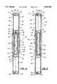
- FIG. 7is a cross-sectional view taken along lines 7--7 of FIG. 6.
- a display system 11is illustrated in FIG. 1 in an operative position on a school bus 12.
- the display system 11is mounted on a school bus 12 and includes a sign assembly 10 which may pivot with respect to the school bus 12 by a mounting assembly 14.
- the sign assembly 10is pivoted to lay against the school bus 12 in a non-use position and extends outwardly from the side of the school bus 12 in a perpendicular orientation in a use position, as illustrated.
- the teachings of the sign assembly 10may be utilized in various other applications and is not specifically limited to application of a school bus or the wording STOP.
- the sign assembly 10includes a molded sign housing 16 having front 18 and rear 20 faces with at least one slotted aperture 22 formed through the front and rear faces 18, 20 defining a predetermined shape.
- a lens 24is connected to the sign housing 16 and has a raised surface portion 26 protruding through the slotted aperture 22 defining at least a portion of the predetermined shape.
- At least one light element 28is connected to and behind the lens 24, opposite the sign housing 16, illuminating the raised surface portion 26 and the slotted aperture 22.
- the sign housing 16includes the front face 18 and rear face 20 opposing one another with peripheral side walls 30 connected between the front and rear faces 18, 20 providing a cavity 32 within the sign housing 16. More specifically, the sign housing 16 is formed by a front molded half 34 and a rear molded half 36, each including a portion or half of the side walls 30 extending therefrom to mating edges 40 to form the peripheral side walls 30 for sealing the sign housing 16.
- the front and rear molded halves 34, 36are preferably injection molded of opaque plastic (i.e., black), but may be molded by other techniques commonly known in the art.
- the half portions of the side walls 30taper away from one another at the mating edges 40 toward the front and rear faces 18, 20.
- the mating edge 40extends slightly outwardly from the periphery of the front and rear faces 18, 20.
- the tapered side walls 30aid in the sealing of the sign housing 16 by directing water or other moisture away from the mating edge 40.
- the mating edges 40 of the front and rear halves 34, 36are also formed by L-shaped lips which mate and engage one another to seal the halves 34, 36 to one another forming the sign housing 16.
- the front and rear halves 34, 36are securely connected to one another by fasteners 42 extending in the peripheral side walls 30 parallel with the front and rear faces 18, 20. More specifically, as illustrated in FIGS. 3-5, one of the side walls 30 includes a flange 44 extending beyond the respective mating edge 40 to lay against the half portion of the side wall 30 of the other of the halves 34, 36. The outward end of the flange 44 includes a flange aperture 45. The flange aperture 45 is aligned with a wall aperture 35 to receive the fastener 42 therethrough to connect the halves 34, 36 to one another.
- Each of the front and rear faces 18, 20are generally planar and include a reflective sheet of material 46 applied to the faces 18, 20.
- This material 46may be a retro-reflective material such as by 3MTM. Such material is commonly used as a reflected element for signs or other types of markers.
- the reflective material 46includes a standard STOP design thereon in red and white colors and of hexagon shape and outline. However, any other design may be utilized as required.
- the reflective material 46includes openings therethrough in the letters forming the word STOP, which are aligned with the slotted apertures 22 in the front and rear faces 18, 20.
- the slotted aperture 22 in the sign housing 16includes a plurality of slotted apertures to form the predetermined shape, such as alphabetic characters forming the word STOP.
- the slotted apertures 22are shaped in the form of the letters STOP and are formed in both the front face 18 and rear face 20. It should be apparent that the word STOP can be externally read from the front face or from the rear face, both faces 18, 20 similarly constructed to provide a two sided sign assembly 10.
- the slotted apertures 22receive the raised surface portions 26 of the lens 24 therethrough as subsequently discussed.
- the interior surfaces of the front and rear faces 18, 20include ribs 48 extending internally in the cavity 32 to outline the lens 24 forming a lens receptacle 49.
- the ribs 48extend from each face 18, 20 and contact each other when assembled to aid in support of the sign assembly 10.
- the lens receptacle 49provides a generally rectangular shape larger than and extending about the area containing the slotted apertures 22 forming the word STOP.
- a top and bottom channel 50is formed extending from the center of the lens receptacle 49 by a second rib 51 to the arms 102 (subsequently discussed) to receive an electrical conductor 52.
- the channel 50allows the conductors 52 from the light element 28 to leave the lens receptacle 49 formed by the ribs 48.
- the channel 50extends from the lens receptacle 49, and along the length thereof to the mounting arms 102, as subsequently discussed.
- Each of the front and rear faces 18, 20also include on their interior side a plurality of mounting bosses 56 extending therefrom the corners established by the lens receptacle 49 and for receiving a fastener 57 to secure the lens 24.
- the lens 24includes a lens housing 60 for containing the light element 28 therein.
- the lens housing 60is generally of a rectangular box shape and includes a front lens 61 and a rear lens 62, and has lens sides 64 interconnecting the lenses 61, 62 to seal the lens housing 60 providing a lens cavity 66 therein.
- the lens housing 60is generally a transparent or translucent material to allow the light element 28 to illuminate therethrough.
- the lens housing 60is of a dimension to fit within the lens receptacle 49 of the sign housing 16.
- Each of the front and rear lenses 61, 62include the raised surface portions 26 extending therefrom which are formed of alphabetic characters or other indica, such as the word STOP.
- the raised surfaces 26are formed of a dimension and configuration to fit through the slotted apertures 22 of the sign housing 16. Therefore, the raised surfaces 26 are also in the form of the word STOP.
- the raised surfaces 26generally include a radius top surface.
- the height of the raised surface portions 26is greater than the thickness of each of the front and rear faces 18, 20 so that the raised surfaces 26 protrude through and extend past the front and rear faces 18, 20. This allows the raised surface portions 26 to project above the planar surface of the front face and rear face 18, 20 so that during illumination, such illumination is visible either from directly looking on the faces 18, 20, or by looking at the side of the sign 10.
- the lens housing 60is injection molded from clear or translucent plastic material, though other manufacturing methods may be utilized.
- the lens housing 60includes the front and rear halves providing the front and rear lenses 61, 62, each with portions of sides 64 extending therefrom to mate at their edges 74 to produce the box-like structure of the lens housing 60.
- the edges 74, as with the mating edges 40 of the sign housing 16,also include an L-shaped lip to seal the lens housing 16.
- the lens housing 60includes at least four mounting apertures 76 on each half face 61, 62 adjacent the corners thereof aligned with the mounting bosses 56, to receive the fasteners 57 therethrough for securing to the mounting bosses 56 of the front sign face 18 and rear sign face 20, respectively.
- the front lens 61is secured against the mounting bosses 56 of the front face 18, and the rear lens 62 is secured onto the mounting bosses 56 of the rear face 20.
- the light element 28comprises a plurality of light emitting diodes (LEDs) to illuminate the word STOP through the sign housing 16.
- the plurality of LEDs 28are positioned in a single row, spaced from one another, forming each letter of the word STOP.
- Such LEDs 28are generally formed and secured onto a substrate or circuit board 82 by known techniques. In the preferred embodiment, a single row of LEDs 28 is utilized for each letter as illustrated.
- the circuit board 82is of a size slightly less than the dimension of the lens cavity 66 so that the board 82 and LEDs 28 may be sealed within the lens housing 60.
- two boards 82are utilized with LEDs 28 positioned in the location of the appropriate letters, and are located back-to-back so that the LEDs 28 of each board 82 extend up into the raised surface 26 of each of the front lens 61 and rear lens 62, respectively.
- the circuit boards 82are aligned with the respective front or rear lens 61, 62, and the lens fasteners 57 are inserted through the board 82 and lens 61, 62 and into the mounting boss 56 on the sign housing 16. This secures the board 82 and lens 61, 62 to each of the respective halves 34, 36 of the sign housing 16. Extending from the boards 82 are the conductors 52 to supply power to the LEDs 28.
- the lens housing 60includes an aperture 83 therein to allow the conductors to pass therethrough and into the channel 50 of the sign housing 16.
- the LEDs 28are sealed within the sign housing 16 by both the sign housing 16 and by the lens housing 60. This prevents deterioration of the electronics due to atmospheric conditions.
- a second embodiment 10'is also disclosed.
- the housing 16'is molded to allow an alternative embodiments to be formed therefrom, where the slotted apertures 22 and raised surfaces 26 are omitted so that the front and rear faces 18', 20' extend continuously planar.
- the same injection molds of the two housing halves 34, 36may be used, with different portions cut therefrom.
- Like primed numeralsare used to identify similar parts of the first embodiment.
- flashing lights 58may be inserted above and below the word STOP, as are positioned in the prior art.
- a reflective material 46'is utilized displaying the STOP letters without opening in the words as in the first embodiment.
- the subject inventionincludes rectangular or square openings 84 in the front and rear faces 18', 20' to receive rectangular shaped lenses 87 therein.
- the sign housing 16'includes a recessed flange 86 for supporting the light lenses 87 so that the outer surface of the flashing light lenses 87 are substantially coplanar or flush with the outer surface of the front and rear faces 18', 20', respectively.
- a peripheral rib 88extends from the flange 86 to provide a light chamber 90 when the halves 34', 36' are assembled.
- a light 28'such as fluorescent light or LEDs, are connected in the chamber 90.
- Power conductors 52' thereforare fed out of the chamber 90 into the channel 50' as in the first embodiment.
- Also includedare a plurality of mounting bosses 92 connected at the corners of the flange 86 to allow for installation of flashing lights 58 with the fasteners 89.
- the first and second embodiment sign housings 16, 16'may be molded from the same injection mold.
- the molded halves 34, 36, 34', 36'may be cut out at either the STOP letters 22 or the flashing lights 58 locations with appropriate added components of either the lens housing 60, etc. or the flashing lights 58.
- the internal structure of the housing 16, 16'remains the same for either embodiment.
- the sign assembly 10, 10'(in both embodiments) includes two mounting arms 102, 102' extending outwardly therefrom to engage and be pivoted by the mounting assembly 14, 14'.
- FIG. 3best illustrates the construction of the mounting arms 102, 102', though both embodiments use the same design.
- the mounting arms 102include an internal arm channel 104 in communication with the channels 50.
- the mounting arms 102include a pair of housing extension arms 106 which extend a length parallel with one another and outwardly from a side of the sign housing 16 to an L-shaped bend 108.
- the extension arms 102are integral with the front molded half 34 and rear molded half 36, each formed by the front and rear halves 34, 36. In other words, the extension arms 102 are formed of two halves as with the remainder of the sign housing 16.
- the arm channel 104extends through the L-shaped bend 108 to an arm opening 110.
- the arm opening 110 of each of the extension arms 106face one another across a gap.
- the mounting arms 102include a hollow L-shaped bushing 112 which is inserted within the arm openings 102 and arm channels 104 of each of the arms 106.
- the bushings 112include a first leg 114 having a first open 115 end receiving the power conductor 52 and extending through the L-shaped bend to a second leg 116.
- the first leg 114includes an open upper side 118 so that the power conductor 52 may be directly fed dow the second leg 116 along a substantially straight angle. In other words, the conductor 52 may be fed through the open upper side 118 and straight down the second leg 116, and then laid against the first leg 114 pulled to follow the L-shaped bend after the conductor is fully fed through the bushing 112.
- the second leg 116includes a male shaped end 120.
- the male shaped end 120is of a hexagon shape as in the prior art and has an opening therethrough.
- the conductors 52are extended through the housing channel 50 and arm channel 104 and through the bushing 112 to the mounting assembly 14.
- a bearing plate 117is formed with the bushing 112 to act against the mounting assembly 14.
- a wear washermay also be placed against the bearing plate 117.
- the mounting assembly 14includes a molded mounting housing 122 having a base 124 and a cover 126 with opposing mounting openings (not shown) for receiving the bushings 112.
- the base 124is secured to the bus 12 by mounting fasteners 125.
- the base 124 and cover 126are fastened to one another via fasteners 130.
- the mounting housing 122supports an actuator (not shown) which is connected to the bushings 112.
- the actuatormay be of any type known in the art, and that particularly described in U.S. Pat. No. 5,357,239.
- the conductors 52extend through the bushing 112 to flashing control circuitry 136.
- the control circuitry 136powers and flashes the LEDs or flashing lights 58.
- the control circuitry 136receives a control signal from the bus operator via a selecting switch 140, which switch 140 may also causes the red lights 200 on the upper ends of the bus 12 to flash.
- the sign 10, 10'is assembled as follows.
- the slotted apertures 22are cut out of both molded halves 34, 36.
- the LEDs 28are placed on both of the boards 82 in the predetermined shape.
- the halves of the lens housing 60 and the boards 82are attached to the front and rear faces 18, 20 of the front molded half 34 and rear molded half 36 of the sign housing 16 at the mounting bosses 56.
- the conductors 52are run through one of the channels 50 and along one of the mounting arms 102 and stretched through the bushing 116.
- the bushing 112is laid within the arm opening 104 in the appropriate location.
- the front molded half 34 and the rear molded half 36are placed against one another and fasteners 42 connected within the side wall 38.
- the areas over the recessed flanges 86are cut out in each half 34', 36'.
- a lens 87is connected by fasteners 89 in the recessed aperture to be flush with the front and rear faces 18', 20'.
- Lights 28'are fixedly connected behind the lenses 87 on one of the halves 34', 36'.
- the conductors 52'are run through one of the channels 50' and out one of the arms 102. Thereafter, the halves 34', 36' are connected to one another.
- the sign assembly 10, 10'may be mounted on the hinge assembly 14, 14' by placing the bushings 112, 112' in the mounting openings, and clamping the housing cover 126 onto the base 124.
Landscapes
- Physics & Mathematics (AREA)
- General Physics & Mathematics (AREA)
- Engineering & Computer Science (AREA)
- Theoretical Computer Science (AREA)
- Illuminated Signs And Luminous Advertising (AREA)
Abstract
Description
Claims (18)
Priority Applications (4)
| Application Number | Priority Date | Filing Date | Title |
|---|---|---|---|
| US08/525,120US5687500A (en) | 1995-09-08 | 1995-09-08 | Stop sign housing with flashing lights |
| CA002184977ACA2184977A1 (en) | 1995-09-08 | 1996-09-06 | Stop sign housing with flashing lights |
| US08/709,482US6009650A (en) | 1995-09-08 | 1996-09-06 | Illuminated sign assembly |
| US09/016,845US6099933A (en) | 1995-09-08 | 1998-01-30 | Illuminated sign assembly |
Applications Claiming Priority (1)
| Application Number | Priority Date | Filing Date | Title |
|---|---|---|---|
| US08/525,120US5687500A (en) | 1995-09-08 | 1995-09-08 | Stop sign housing with flashing lights |
Related Child Applications (2)
| Application Number | Title | Priority Date | Filing Date |
|---|---|---|---|
| US08/709,482Continuation-In-PartUS6009650A (en) | 1995-09-08 | 1996-09-06 | Illuminated sign assembly |
| US09/016,845Continuation-In-PartUS6099933A (en) | 1995-09-08 | 1998-01-30 | Illuminated sign assembly |
Publications (1)
| Publication Number | Publication Date |
|---|---|
| US5687500Atrue US5687500A (en) | 1997-11-18 |
Family
ID=24092007
Family Applications (1)
| Application Number | Title | Priority Date | Filing Date |
|---|---|---|---|
| US08/525,120Expired - LifetimeUS5687500A (en) | 1995-09-08 | 1995-09-08 | Stop sign housing with flashing lights |
Country Status (2)
| Country | Link |
|---|---|
| US (1) | US5687500A (en) |
| CA (1) | CA2184977A1 (en) |
Cited By (21)
| Publication number | Priority date | Publication date | Assignee | Title |
|---|---|---|---|---|
| US5905441A (en)* | 1996-09-10 | 1999-05-18 | Klee; Edward L. | Hand-held visual signaling device |
| US6031468A (en)* | 1998-12-21 | 2000-02-29 | Chinotech International, Inc. | Warning light adapted for use with a stop sign |
| US6134820A (en)* | 1999-03-26 | 2000-10-24 | Martinez; Robert L. | Hand-held safety signal |
| US6150957A (en)* | 1998-07-10 | 2000-11-21 | Henz; Richard M. | Lighted sign and warning device |
| US20030121467A1 (en)* | 2001-12-27 | 2003-07-03 | Yazaki Corporation | Indicator |
| US20030174501A1 (en)* | 2001-04-13 | 2003-09-18 | Patrick Martineau | LED symbol signal |
| US20040081721A1 (en)* | 2002-10-28 | 2004-04-29 | Underwood J. Larry | Apparatus for molding emergency exit signs |
| US20040104810A1 (en)* | 2002-11-12 | 2004-06-03 | Scott Burke H. | Hand held illuminated safety signal |
| US6765481B2 (en) | 2001-11-13 | 2004-07-20 | Transpec, Inc. | Electrical actuator assembly for hinged vehicle safety devices |
| US6812856B2 (en) | 2001-09-12 | 2004-11-02 | Endless Visions, Inc. | Lighted traffic sign attached to portable restroom |
| US6869203B2 (en)* | 2001-04-13 | 2005-03-22 | Gelcore Llc | LED symbol signal |
| US20060012487A1 (en)* | 2004-07-16 | 2006-01-19 | Gibson Thomas W | Traffic control sign assembly |
| US20060012486A1 (en)* | 2004-07-16 | 2006-01-19 | Gibson Thomas W | Traffic control sign assembly |
| US20080247183A1 (en)* | 2007-03-09 | 2008-10-09 | Heavy Duty Bus Parts, Inc. | Bus stop arm and lamp for bus stop arm |
| US20110069486A1 (en)* | 2009-09-18 | 2011-03-24 | Martin John D | Lighting Arrangement Using LEDs |
| US8449142B1 (en) | 2009-10-14 | 2013-05-28 | C-M Glo, Llc | Reinforced housing structure for a lighted sign or lighting fixture |
| US9286815B1 (en) | 2014-03-26 | 2016-03-15 | Dale E. Smith | Stop sign apparatus |
| US9640096B2 (en) | 2014-12-18 | 2017-05-02 | Adote G. Akwei | Traffic direction assembly |
| US20190001880A1 (en)* | 2017-06-29 | 2019-01-03 | Jvis-Usa, Llc | Vehicle interior trim assembly configured to form a light pattern having an emblem shape at the front of a trim part such as an air bag cover |
| CN112638711A (en)* | 2018-07-13 | 2021-04-09 | 思玛德供应有限公司 | School bus parking signal arm and driving unit thereof |
| US11554715B2 (en)* | 2018-07-13 | 2023-01-17 | Smartrend Manufacturing Group (Smg), Inc. | School bus stop arm and drive unit therefor |
Citations (15)
| Publication number | Priority date | Publication date | Assignee | Title |
|---|---|---|---|---|
| US850521A (en)* | 1906-11-20 | 1907-04-16 | Charles L Carter | Illuminated sign. |
| US1730027A (en)* | 1924-05-10 | 1929-10-01 | Amelia Craven | Automobile signal |
| US1803743A (en)* | 1929-01-03 | 1931-05-05 | Wiedemann Harold | Display tablet |
| US2080991A (en)* | 1934-12-07 | 1937-05-18 | Hugh E Young | Warning sign |
| US4112482A (en)* | 1977-05-09 | 1978-09-05 | Virgil Powell | Night light belt |
| US4559518A (en)* | 1982-09-22 | 1985-12-17 | Specialty Manufacturing Co. | School bus stop sign and crossing arm apparatus |
| US4841288A (en)* | 1988-02-22 | 1989-06-20 | Addicks Lyle F | Earthquake illuminating device |
| US4891896A (en)* | 1988-08-15 | 1990-01-09 | Gulf Development Corporation | Simulated neon sign |
| US5036307A (en)* | 1990-06-04 | 1991-07-30 | School Bus Parts Co. Of Canada, Inc. | Weather resistant control system for school bus safety device |
| US5166663A (en)* | 1991-02-20 | 1992-11-24 | Kenneth Leis | Self contained air operated pivoting sign device for vehicle |
| US5276424A (en)* | 1992-04-20 | 1994-01-04 | Hegemann John J | Attention getting sign |
| US5299109A (en)* | 1992-11-10 | 1994-03-29 | High Lites, Inc. | LED exit light fixture |
| US5303124A (en)* | 1993-07-21 | 1994-04-12 | Avi Wrobel | Self-energizing LED lamp |
| US5345705A (en)* | 1992-05-20 | 1994-09-13 | Lawrence Gary L | Lightweight, three-dimensional sign |
| US5357239A (en)* | 1993-05-17 | 1994-10-18 | Transpec, Inc. | Actuating device for bus safety gate and stop sign |
- 1995
- 1995-09-08USUS08/525,120patent/US5687500A/ennot_activeExpired - Lifetime
- 1996
- 1996-09-06CACA002184977Apatent/CA2184977A1/ennot_activeAbandoned
Patent Citations (15)
| Publication number | Priority date | Publication date | Assignee | Title |
|---|---|---|---|---|
| US850521A (en)* | 1906-11-20 | 1907-04-16 | Charles L Carter | Illuminated sign. |
| US1730027A (en)* | 1924-05-10 | 1929-10-01 | Amelia Craven | Automobile signal |
| US1803743A (en)* | 1929-01-03 | 1931-05-05 | Wiedemann Harold | Display tablet |
| US2080991A (en)* | 1934-12-07 | 1937-05-18 | Hugh E Young | Warning sign |
| US4112482A (en)* | 1977-05-09 | 1978-09-05 | Virgil Powell | Night light belt |
| US4559518A (en)* | 1982-09-22 | 1985-12-17 | Specialty Manufacturing Co. | School bus stop sign and crossing arm apparatus |
| US4841288A (en)* | 1988-02-22 | 1989-06-20 | Addicks Lyle F | Earthquake illuminating device |
| US4891896A (en)* | 1988-08-15 | 1990-01-09 | Gulf Development Corporation | Simulated neon sign |
| US5036307A (en)* | 1990-06-04 | 1991-07-30 | School Bus Parts Co. Of Canada, Inc. | Weather resistant control system for school bus safety device |
| US5166663A (en)* | 1991-02-20 | 1992-11-24 | Kenneth Leis | Self contained air operated pivoting sign device for vehicle |
| US5276424A (en)* | 1992-04-20 | 1994-01-04 | Hegemann John J | Attention getting sign |
| US5345705A (en)* | 1992-05-20 | 1994-09-13 | Lawrence Gary L | Lightweight, three-dimensional sign |
| US5299109A (en)* | 1992-11-10 | 1994-03-29 | High Lites, Inc. | LED exit light fixture |
| US5357239A (en)* | 1993-05-17 | 1994-10-18 | Transpec, Inc. | Actuating device for bus safety gate and stop sign |
| US5303124A (en)* | 1993-07-21 | 1994-04-12 | Avi Wrobel | Self-energizing LED lamp |
Cited By (37)
| Publication number | Priority date | Publication date | Assignee | Title |
|---|---|---|---|---|
| US5905441A (en)* | 1996-09-10 | 1999-05-18 | Klee; Edward L. | Hand-held visual signaling device |
| US6150957A (en)* | 1998-07-10 | 2000-11-21 | Henz; Richard M. | Lighted sign and warning device |
| US6031468A (en)* | 1998-12-21 | 2000-02-29 | Chinotech International, Inc. | Warning light adapted for use with a stop sign |
| US6134820A (en)* | 1999-03-26 | 2000-10-24 | Martinez; Robert L. | Hand-held safety signal |
| US6363641B1 (en)* | 1999-03-26 | 2002-04-02 | Am And Pm Safety, Llc | Hand-held safety signal |
| US20030174501A1 (en)* | 2001-04-13 | 2003-09-18 | Patrick Martineau | LED symbol signal |
| US6955449B2 (en) | 2001-04-13 | 2005-10-18 | Gelcore Llc | LED symbol signal |
| US20050128768A1 (en)* | 2001-04-13 | 2005-06-16 | Patrick Martineau | Led symbol signal |
| US6869203B2 (en)* | 2001-04-13 | 2005-03-22 | Gelcore Llc | LED symbol signal |
| US7175305B2 (en) | 2001-04-13 | 2007-02-13 | Gelcore Llc | LED symbol signal |
| US6812856B2 (en) | 2001-09-12 | 2004-11-02 | Endless Visions, Inc. | Lighted traffic sign attached to portable restroom |
| US20040201498A1 (en)* | 2001-11-13 | 2004-10-14 | Haigh James A. | Electrical actuator assembly for hinged vehicle safety devices |
| US6765481B2 (en) | 2001-11-13 | 2004-07-20 | Transpec, Inc. | Electrical actuator assembly for hinged vehicle safety devices |
| US7005973B2 (en) | 2001-11-13 | 2006-02-28 | Transpec, Inc. | Electrical actuator assembly for hinged vehicle safety devices |
| US6904866B2 (en)* | 2001-12-27 | 2005-06-14 | Yazaki Corporation | Indicator |
| US20030121467A1 (en)* | 2001-12-27 | 2003-07-03 | Yazaki Corporation | Indicator |
| US20040081721A1 (en)* | 2002-10-28 | 2004-04-29 | Underwood J. Larry | Apparatus for molding emergency exit signs |
| US7047679B2 (en)* | 2002-10-28 | 2006-05-23 | L. L. Culmat, L.P. | Molded sign facing plate |
| US20040104810A1 (en)* | 2002-11-12 | 2004-06-03 | Scott Burke H. | Hand held illuminated safety signal |
| WO2004084265A3 (en)* | 2003-03-13 | 2005-04-14 | Gelcore Llc | Led symbol signal |
| AU2004220849B2 (en)* | 2003-03-13 | 2009-09-24 | Gelcore Llc | Led symbol signal |
| US20060012486A1 (en)* | 2004-07-16 | 2006-01-19 | Gibson Thomas W | Traffic control sign assembly |
| US7233259B2 (en) | 2004-07-16 | 2007-06-19 | Gibson Thomas W | Traffic control sign assembly |
| US20060012487A1 (en)* | 2004-07-16 | 2006-01-19 | Gibson Thomas W | Traffic control sign assembly |
| US20080247183A1 (en)* | 2007-03-09 | 2008-10-09 | Heavy Duty Bus Parts, Inc. | Bus stop arm and lamp for bus stop arm |
| US20110069486A1 (en)* | 2009-09-18 | 2011-03-24 | Martin John D | Lighting Arrangement Using LEDs |
| US8449140B2 (en) | 2009-09-18 | 2013-05-28 | C-M Glo, Llc | Lighting arrangement using LEDs |
| US8449142B1 (en) | 2009-10-14 | 2013-05-28 | C-M Glo, Llc | Reinforced housing structure for a lighted sign or lighting fixture |
| US9286815B1 (en) | 2014-03-26 | 2016-03-15 | Dale E. Smith | Stop sign apparatus |
| US9640096B2 (en) | 2014-12-18 | 2017-05-02 | Adote G. Akwei | Traffic direction assembly |
| US20190001880A1 (en)* | 2017-06-29 | 2019-01-03 | Jvis-Usa, Llc | Vehicle interior trim assembly configured to form a light pattern having an emblem shape at the front of a trim part such as an air bag cover |
| US10507764B2 (en)* | 2017-06-29 | 2019-12-17 | Jvis-Usa, Llc | Vehicle interior trim assembly configured to form a light pattern having an emblem shape at the front of a trim part such as an air bag cover |
| CN112638711A (en)* | 2018-07-13 | 2021-04-09 | 思玛德供应有限公司 | School bus parking signal arm and driving unit thereof |
| US11554715B2 (en)* | 2018-07-13 | 2023-01-17 | Smartrend Manufacturing Group (Smg), Inc. | School bus stop arm and drive unit therefor |
| US11820283B2 (en)* | 2018-07-13 | 2023-11-21 | Smartrend Manufacturing Group (Smg), Inc. | School bus stop arm and drive unit therefor |
| US20240025335A1 (en)* | 2018-07-13 | 2024-01-25 | Smartrend Manufacturing Group (Smg), Inc. | School bus stop arm and drive unit therefor |
| US12358425B2 (en)* | 2018-07-13 | 2025-07-15 | Smartrend Manufacturing Group (Smg), Inc. | School bus stop arm and drive unit therefor |
Also Published As
| Publication number | Publication date |
|---|---|
| CA2184977A1 (en) | 1997-03-09 |
Similar Documents
| Publication | Publication Date | Title |
|---|---|---|
| US5634287A (en) | Illuminated sign housing assembly | |
| US5687500A (en) | Stop sign housing with flashing lights | |
| US5796331A (en) | Illuminated pivotal sign assembly | |
| US6009650A (en) | Illuminated sign assembly | |
| US7121700B1 (en) | Vehicle advertising sign illumination apparatus | |
| US4683359A (en) | Illuminated switch assembly with combined light and light shield | |
| US5005306A (en) | Illuminated vehicle sign | |
| US5797672A (en) | Safety light | |
| US5539623A (en) | Lighting device used in an exit sign | |
| US4860476A (en) | Automobile display device | |
| US7220019B2 (en) | Multi-color illuminated sign | |
| US5572812A (en) | Number plate including luminous characters | |
| US5542200A (en) | Number plate including luminous characters | |
| US5073842A (en) | Anti-theft illuminated display device | |
| US5442526A (en) | Vehicle reflector illuminating system | |
| US6565244B1 (en) | Single source identification light bar | |
| US6860047B1 (en) | Illuminated flag decal | |
| US20080123359A1 (en) | Illuminated display system for a vehicle | |
| US6099933A (en) | Illuminated sign assembly | |
| EP2788223B1 (en) | Light emitting diode perimeter lamp assembly | |
| US4688343A (en) | Message dome for automotive vehicles | |
| US5272603A (en) | Light fixture | |
| US20080016734A1 (en) | Illuminated sign and method of making | |
| JP3137551B2 (en) | Display device and display element unit | |
| US2121093A (en) | Traffic signal |
Legal Events
| Date | Code | Title | Description |
|---|---|---|---|
| AS | Assignment | Owner name:TRANSPEC INC., MICHIGAN Free format text:ASSIGNMENT OF ASSIGNORS INTEREST;ASSIGNOR:LAMPARTER, RONALD C.;REEL/FRAME:007671/0700 Effective date:19950906 | |
| STCF | Information on status: patent grant | Free format text:PATENTED CASE | |
| FPAY | Fee payment | Year of fee payment:4 | |
| FPAY | Fee payment | Year of fee payment:8 | |
| AS | Assignment | Owner name:SPECIALTY MANUFACTURING, INC., NORTH CAROLINA Free format text:ASSIGNMENT OF ASSIGNORS INTEREST;ASSIGNOR:TRANSPEC, INC;REEL/FRAME:019649/0137 Effective date:20070621 | |
| FPAY | Fee payment | Year of fee payment:12 | |
| AS | Assignment | Owner name:BNP PARIBAS, AS ADMINISTRATIVE AGENT, NEW YORK Free format text:GRANT OF PATENT SECURITY INTEREST;ASSIGNOR:SPECIALTY MANUFACTURING, INC.;REEL/FRAME:031396/0189 Effective date:20130930 | |
| AS | Assignment | Owner name:OCM FIE, LLC, AS ADMINISTRATIVE AGENT, NEW YORK Free format text:GRANT OF SECOND LIEN PATENT SECURITY AGREEMENT;ASSIGNOR:SPECIALTY MANUFACTURING, INC.;REEL/FRAME:031413/0738 Effective date:20130930 | |
| AS | Assignment | Owner name:ELKHART BRASS MANUFACTURING COMPANY, INC., MISSOUR Free format text:RELEASE BY SECURED PARTY;ASSIGNOR:BNP PARIBAS;REEL/FRAME:045234/0663 Effective date:20180201 Owner name:RANDALL MANUFACTURING LLC, MISSOURI Free format text:RELEASE BY SECURED PARTY;ASSIGNOR:BNP PARIBAS;REEL/FRAME:045234/0663 Effective date:20180201 Owner name:FIRE RESEARCH CORP., MISSOURI Free format text:RELEASE BY SECURED PARTY;ASSIGNOR:BNP PARIBAS;REEL/FRAME:045234/0663 Effective date:20180201 Owner name:ROM ACQUISITION CORPORATION, MISSOURI Free format text:RELEASE BY SECURED PARTY;ASSIGNOR:BNP PARIBAS;REEL/FRAME:045234/0663 Effective date:20180201 Owner name:ELKHART BRASS MANUFACTURING COMPANY, INC., MISSOUR Free format text:RELEASE BY SECURED PARTY;ASSIGNOR:OCM FIE, LLC;REEL/FRAME:045234/0627 Effective date:20180201 Owner name:REAR VIEW SAFETY INC., MISSOURI Free format text:RELEASE BY SECURED PARTY;ASSIGNOR:BNP PARIBAS;REEL/FRAME:045234/0663 Effective date:20180201 Owner name:IEM, INC., MISSOURI Free format text:RELEASE BY SECURED PARTY;ASSIGNOR:OCM FIE, LLC;REEL/FRAME:045234/0627 Effective date:20180201 Owner name:FIRE RESEARCH CORP., MISSOURI Free format text:RELEASE BY SECURED PARTY;ASSIGNOR:OCM FIE, LLC;REEL/FRAME:045234/0627 Effective date:20180201 Owner name:IEM, INC., MISSOURI Free format text:RELEASE BY SECURED PARTY;ASSIGNOR:BNP PARIBAS;REEL/FRAME:045234/0663 Effective date:20180201 Owner name:ROM ACQUISITION CORPORATION, MISSOURI Free format text:RELEASE BY SECURED PARTY;ASSIGNOR:OCM FIE, LLC;REEL/FRAME:045234/0627 Effective date:20180201 Owner name:SPECIALTY MANUFACTURING, INC., MISSOURI Free format text:RELEASE BY SECURED PARTY;ASSIGNOR:BNP PARIBAS;REEL/FRAME:045234/0663 Effective date:20180201 Owner name:SPECIALTY MANUFACTURING, INC., MISSOURI Free format text:RELEASE BY SECURED PARTY;ASSIGNOR:OCM FIE, LLC;REEL/FRAME:045234/0627 Effective date:20180201 Owner name:RANDALL MANUFACTURING LLC, MISSOURI Free format text:RELEASE BY SECURED PARTY;ASSIGNOR:OCM FIE, LLC;REEL/FRAME:045234/0627 Effective date:20180201 Owner name:REAR VIEW SAFETY INC., MISSOURI Free format text:RELEASE BY SECURED PARTY;ASSIGNOR:OCM FIE, LLC;REEL/FRAME:045234/0627 Effective date:20180201 |