US5687242A - Hearing aid controls operable with battery door - Google Patents
Hearing aid controls operable with battery doorDownload PDFInfo
- Publication number
- US5687242A US5687242AUS08/514,153US51415395AUS5687242AUS 5687242 AUS5687242 AUS 5687242AUS 51415395 AUS51415395 AUS 51415395AUS 5687242 AUS5687242 AUS 5687242A
- Authority
- US
- United States
- Prior art keywords
- switch
- battery door
- battery
- hearing aid
- door
- Prior art date
- Legal status (The legal status is an assumption and is not a legal conclusion. Google has not performed a legal analysis and makes no representation as to the accuracy of the status listed.)
- Expired - Fee Related
Links
Images


Classifications
- H—ELECTRICITY
- H04—ELECTRIC COMMUNICATION TECHNIQUE
- H04R—LOUDSPEAKERS, MICROPHONES, GRAMOPHONE PICK-UPS OR LIKE ACOUSTIC ELECTROMECHANICAL TRANSDUCERS; DEAF-AID SETS; PUBLIC ADDRESS SYSTEMS
- H04R25/00—Deaf-aid sets, i.e. electro-acoustic or electro-mechanical hearing aids; Electric tinnitus maskers providing an auditory perception
- H04R25/60—Mounting or interconnection of hearing aid parts, e.g. inside tips, housings or to ossicles
- H04R25/602—Mounting or interconnection of hearing aid parts, e.g. inside tips, housings or to ossicles of batteries
- H—ELECTRICITY
- H01—ELECTRIC ELEMENTS
- H01H—ELECTRIC SWITCHES; RELAYS; SELECTORS; EMERGENCY PROTECTIVE DEVICES
- H01H2300/00—Orthogonal indexing scheme relating to electric switches, relays, selectors or emergency protective devices covered by H01H
- H01H2300/004—Application hearing aid
- H—ELECTRICITY
- H04—ELECTRIC COMMUNICATION TECHNIQUE
- H04R—LOUDSPEAKERS, MICROPHONES, GRAMOPHONE PICK-UPS OR LIKE ACOUSTIC ELECTROMECHANICAL TRANSDUCERS; DEAF-AID SETS; PUBLIC ADDRESS SYSTEMS
- H04R2225/00—Details of deaf aids covered by H04R25/00, not provided for in any of its subgroups
- H04R2225/61—Aspects relating to mechanical or electronic switches or control elements, e.g. functioning
- H—ELECTRICITY
- H04—ELECTRIC COMMUNICATION TECHNIQUE
- H04R—LOUDSPEAKERS, MICROPHONES, GRAMOPHONE PICK-UPS OR LIKE ACOUSTIC ELECTROMECHANICAL TRANSDUCERS; DEAF-AID SETS; PUBLIC ADDRESS SYSTEMS
- H04R25/00—Deaf-aid sets, i.e. electro-acoustic or electro-mechanical hearing aids; Electric tinnitus maskers providing an auditory perception
- H04R25/60—Mounting or interconnection of hearing aid parts, e.g. inside tips, housings or to ossicles
- H04R25/603—Mounting or interconnection of hearing aid parts, e.g. inside tips, housings or to ossicles of mechanical or electronic switches or control elements
Definitions
- the present inventionrelates to an apparatus for controlling the operation of a hearing aid. More particularly, the present invention relates to a hearing aid wherein the operation of the hearing aid is controlled by movement of a battery door.
- each type of hearing aidis controlled by one or more switches.
- switches controlinclude on/off control, volume control, trimmer applications such as noise filtration control, and telecoil control such as a telephone receiver mode, etc.
- a primary method of controlling the operation of the hearing aidis through a potentiometer that is mounted on the faceplate of the hearing aid.
- the potentiometerFor the potentiometer to be mounted on the faceplate, the potentiometer must be quite small, typically less than 0.25 inches in diameter. The size of the potentiometer poses difficulties in operating and reliably mounting the potentiometer in the hearing aid.
- the present inventionincludes a hearing aid.
- the hearing aidhas a faceplate, an audio component, a battery door, and a switch.
- the faceplatehas an opening formed therein for receiving the battery door.
- the battery doorhas a switch activation area and is capable of receiving a battery therein.
- the battery dooris movable within the opening.
- the switchis operably connected to a hearing aid audio component and is disposed within the hearing aid such that the switch activation area can activate the switch for control of the audio component.
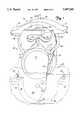
- FIG. 1is a perspective view of a hearing aid switch apparatus of the present invention.
- FIG. 2is a sectional view of the hearing air switch apparatus in an assembled configuration.
- FIG. 3is a sectional view of an alternative embodiment of the hearing aid switch apparatus.
- FIG. 4is a sectional view of another alternative embodiment of the hearing aid switch apparatus.
- FIGS. 1 and 2illustrate one embodiment of a hearing aid 10, according to the present invention, including a battery 12, a battery door 14, a battery door boot 16, a faceplate 20, and hearing aid control switches 22 and 24.
- the hearing aid control switches 22 and 24are operable with and controlled by movement of the battery door 14 relative to the faceplate 20.
- the size and arrangement of the componentsis reduced, thereby reducing the size of the faceplate 20 and the overall dimensions of the hearing aid 10. Since the battery door 14 is physically larger than a typical independent control switch, such as a potentiometer, the hearing aid 10 of the present invention is easier to operate than the prior art hearing aids.
- the battery 12 and the faceplate 20are conventional components that are well known in the art.
- the battery door boot 16is molded into the faceplate 20 for receiving the battery door 14.
- the battery door bootis defined by a plurality of opposed side walls 26 and a base wall 28 that extend between the side walls 26.
- the battery door 14is movable within the battery door boot 16 such that the battery door 14 is operable with one or more of the hearing aid control switches 22 and 24 for controlling the operation of the hearing aid 10.
- the battery door 14may be pivotally mounted about central pivot pins 30 that are mounted to the side walls 26 in the battery door boot 16.
- the hearing aid control switches 22 and 24are shown as a pair of rubber conductive rubber switches, each of which is mounted on a printed circuit board 32 and 34, respectively, for controlling the switch circuitry.
- Each of the conductive switches 22 and 24includes an upper contact 36, a lower contact 38, and a rubber shell 40 as best illustrated in FIG. 2.
- the rubber shell 40provides an air tight seal over the upper and lower contacts 36 and 38 to prevent impurities from affecting the switch operation.
- the upper contact 36is preferably bonded to an inner surface of the rubber shell 40.
- the elasticity of the rubber shell 40maintains the upper contact 36 spaced apart from the lower contact 38, thereby biasing the conductive switches 22 and 24 in an open position.
- an external forcemust be applied to an exterior of one of the rubber shells 40 to deform it and force the upper contact 36 into electrical communication with the lower contact 38.
- the rubber shell 40springs back to its original shape thereby separating the upper contact 36 from the lower contact 38.
- Other switchessuch as membrane sandwich switches as set forth in U.S. patent application Ser. No. 08/273,200, which is assigned to the same assignee as the present application, may also be used and are hereby incorporated by reference.
- the battery door 14includes a base portion 42, a first leg portion 44, a second leg portion 46, a positive battery contact 48, a negative battery contact 50, a first switch activation area 52, and a second switch activation area 54.
- the base portion 42is visible and accessible from an exterior of the hearing aid 10 and provides the main cover and housing for the battery 12.
- the first leg portion 44extends from a first end of the base portion 42 into the battery door boot 16.
- the second leg portion 46extends from a second end of the base portion 42 into the battery door boot 16.
- Each leg portion 44 and 46is preferably arcuate in shape to conform to the shape of the battery 12. Additionally, each leg portion 44 and 46 is preferably constructed of a flexible plastic material or the like, so that each leg portion 44 and 46 can flex in the directions of double headed arrow 60, thereby permitting the battery 12 to be force fit into and removed from the battery door 14. The battery 12 is thereby retained within the battery door 14 by the base portion 42, leg portions 44 and 46 and battery contacts 48 and 50.
- the positive contact 48is mounted into one side of the leg portions 44 and 46 and the base portion 42 of the battery door 14.
- the negative contact 50is mounted into an opposite side of the leg portions 44 and 46 and base portion 42 of the battery door 14.
- Each contact 48 and 50includes a first end portion 62 molded into first leg portion 44, a second end portion 64 molded into the second leg portion 46, a scribe tab 66 for contacting the battery 12, a flex pivot area 68 in the center of the battery door 14 between the first and second end portions 62 and 64, and a contact tab 70 on the second end portion 64.
- the flex pivot area 68includes a semicircular recess 72, which is adapted to receive the pivot pin 30.
- the interaction between the semicircular recess 72 and the pivot pin 30allows the battery door 14 to pivot within the battery door boot 16.
- the semicircular recess 72also allows the battery door 14 to be removed from the battery door boot 16 for replacement of the battery 12 or maintenance of the switches 22 and 24.
- the contact tab 70allows a flex connector 74 or solenoid lead to be connected with the battery 12 and the hearing aid circuitry (not shown).
- the battery door boot 16also preferably includes an aperture 76, which is adapted to receive the flex connector 74.
- the aperture 76allows a length of the flex connector 74 that is in the battery door boot 16 to be adjusted so that the flex connector 74 does not interfere with the pivoting of the battery door 14 in the battery door boot 16.
- the first switch activation area 52is located proximate to an end of the base portion 42 adjacent to the first leg portion 44, and the second switch activation area 54 is located proximate to an end of the base portion 42 adjacent to the second leg portion 46.
- the first and second switch activation areas 52 and 54are shown as outward lateral extensions 78 and 80, respectively, from the base 42. Each lateral extension 78 and 80 overlays one of the switches 22 and 24, respectively.
- the battery door 14also preferably includes a handle 58 that is mounted on the base portion 42.
- the handle 58provides a grip to assist in pivoting of the battery door 14 in the battery door boot 16 or removing the battery door 14 from the battery door boot 16.
- An external force applied to the first switch activation area 52causes the battery door 14 to pivot about pivot pins 30 as indicated by arrow 84. Pivoting causes the first lateral extension 78 to contact the rubber shell 40 and close the first conductive switch 22 for hearing aid control. Upon removal of the external force, the rubber shell 40 springs back to its original position to open the first conductive switch 22 and thereby return the first lateral extension 78 to its original position.
- An external force applied to the second switch activation area 54causes the battery door 14 to pivot in an opposite direction about pivot pins 30 as indicated by arrow 86. Pivoting causes the second lateral extension 80 to contact the rubber shell 40 and dose the second conductive switch 24 for hearing aid control. Upon removal of the external force, the rubber shell 40 springs back to its original position to open the second conductive switch 24 and thereby return the second lateral extension 80 to its original position.
- the conductive switches 22 and 24control amplification volume
- activation of the first control switch 22increases the volume while activation of the second control switch 24 deceases the volume.
- the conductive switches 22 and 24 and circuitrymay be programmed to be incremental switches such that the volume is increased or decreased at discrete incremental levels upon each activation of the switch.
- the conductive switches 22 and 24 and circuitrymay be programmed to be analog switches such that the volume is increased or decreased depending on the amount of time the switch is closed.
- one conductive switch 22may control one hearing aid function while the other conductive switch 24 may control another hearing aid function.
- a conductive switch 22 or 24is activated and held closed to increase volume, for example. After the same switch is released, its next activation decreases the volume, and so on. It is to be noted that the placement of the switches 22 and 24 may be varied along the entire battery door boot 16 so long as the conductive switch 22 and 24 are activated by motion of the battery door 14.
- control switches 122 and 124 in the hearing aid 100has been varied in accordance with the teachings of the present invention as illustrated in FIG. 3. More particularly, the battery door 114 and battery door boot 116 have been modified so that the control switches 122 and 124 are formed on an underside of the battery door boot 116.
- the battery door boot 116includes first and second flanges 130 and 132, and a channel 136 therebetween.
- the control switches 122 and 124are located on the first and second flanges 130 and 132, respectively, and oriented so as to face each other.
- the battery contacts 134are preferably molded into the battery door boot 116 along opposite sides of the battery door 114. Other than this difference, the battery contacts 134 are similar to the battery contacts described with reference to the embodiment illustrated in FIGS. 1 and 2.
- the battery door 114includes a base portion 140, a semicircular portion 142, a first switch activation area 152, a second switch activation area 154, and a switch activator lever 156.
- the semicircular portion 142extends from the base portion 140 to form a receptacle that is adapted to receive a battery 150.
- An exterior edge 144 of the semicircular portion 142substantially conforms with the surface of the battery door boot 116.
- An interior edge 146 of the semicircular portion 142substantially conforms with a profile of the battery 150. The battery door 114 thereby retains the battery 150 in the battery door boot 116 so that the battery 150 is adjacent to and in contact with the battery contacts 134.
- the first and second switch activation areas 152 and 154have characteristics similar to the switch activation areas described with reference to the embodiment illustrated in FIGS. 1 and 2.
- the switch activator lever 156is an extension on an underside of the battery door 114 and extends through the channel 136 in between the first and second conductive switches 122 and 124.
- the first and second conductive switches 122 and 124operate in the same manner as the switches shown and described with respect to the embodiment illustrated in FIGS. 1 and 2.
- the battery door 114also preferably includes a handle 158 that extends from the base portion 140. Similar to the handle shown and described with respect to the embodiment illustrated in FIGS. 1 and 2, the handle 158 provides a grip for pivoting of the battery door 114 in the battery door boot 116 and removing the battery door 114 from the battery door boot 116.
- the battery door 114Upon applying external pressure to the first switch activation area 152, the battery door 114 pivots in the battery door boot 116 as indicated by arrow 170. Pivoting of the battery door 114 causes the switch activator lever 156 to contact and close the first conductive switch 122 for performing a hearing aid control function. When the external pressure is removed, the resilient nature of the conductive switch 122 returns the battery door 114 to its original position.
- the battery door 114pivots in the battery door boot 116 as indicated by arrow 180. Pivoting of the battery door 114 causes the switch activator lever 156 to contact and close the second conductive switch 124 for performing a hearing aid control function.
- a faceplate 220has an opening 224 that is adapted to receive a battery door 214.
- the faceplate 220includes battery contacts 234 that are molded into the faceplate 220 so as to extend across the opening 224.
- the faceplate 220also includes pivot pins 230 that are mounted into edges of the faceplate 220 between the battery contacts 234.
- the battery door 214has a base portion 240 and a semicircular portion 242.
- the semicircular portion 242extends from the base portion 240 to form a circular receptacle that is adapted to receive a battery 250.
- An interior edge 246 of the semicircular portion 242substantially conforms with the profile of the battery 250.
- the semicircular portion 242includes channels 232 that are adapted to receive the pivot pins 230.
- the battery door channels 232retain the battery door 214 in a desired orientation with respect to the faceplate 220 and allow the battery door 214 to slide in a reciprocating motion with respect to the faceplate 220 as indicated by arrow 270.
- a battery door bootsuch as was described with reference to FIGS. 1 and 2, is not needed as the battery door 214 is held in position at the pivot pins 230.
- the battery door 214includes a switch activation area in the form of a handle 278 protruding from a top surface of the battery door 214, and a switch actuator lever 256 that extends from an underside of the battery door 214.
- the handle 278also provides a grip to remove the battery door 214 from the faceplate 220.
- a single control switch 222is positioned below the switch actuator lever 256.
- the battery door 214Upon applying external pressure to the switch activation area 250, the battery door 214 is reciprocated downward in the direction of arrow 270 as the housing pins 230 move in battery door channels 232. The movement of the battery door 214 causes the switch activator lever 256 to contact and close the control switch 222 for performing a hearing aid control function.
- the resilient nature of the control switch 222returns the battery door 214 to its original position.
- the switch and switch circuitryoperate in a similar manner to the switches shown and described with respect to the embodiment illustrated in FIGS. 1 and 2.
- the switch 222is activated by depression of the battery door handle 278 and held closed to incrementally increase the volume, for example. After the switch 222 is released, the next switch activation incrementally decreases the volume, and so on.
Landscapes
- Health & Medical Sciences (AREA)
- General Health & Medical Sciences (AREA)
- Neurosurgery (AREA)
- Otolaryngology (AREA)
- Physics & Mathematics (AREA)
- Engineering & Computer Science (AREA)
- Acoustics & Sound (AREA)
- Signal Processing (AREA)
- Battery Mounting, Suspending (AREA)
Abstract
Description
Claims (21)
Priority Applications (1)
| Application Number | Priority Date | Filing Date | Title |
|---|---|---|---|
| US08/514,153US5687242A (en) | 1995-08-11 | 1995-08-11 | Hearing aid controls operable with battery door |
Applications Claiming Priority (1)
| Application Number | Priority Date | Filing Date | Title |
|---|---|---|---|
| US08/514,153US5687242A (en) | 1995-08-11 | 1995-08-11 | Hearing aid controls operable with battery door |
Publications (1)
| Publication Number | Publication Date |
|---|---|
| US5687242Atrue US5687242A (en) | 1997-11-11 |
Family
ID=24046013
Family Applications (1)
| Application Number | Title | Priority Date | Filing Date |
|---|---|---|---|
| US08/514,153Expired - Fee RelatedUS5687242A (en) | 1995-08-11 | 1995-08-11 | Hearing aid controls operable with battery door |
Country Status (1)
| Country | Link |
|---|---|
| US (1) | US5687242A (en) |
Cited By (55)
| Publication number | Priority date | Publication date | Assignee | Title |
|---|---|---|---|---|
| US5995636A (en)* | 1904-09-29 | 1999-11-30 | Topholm & Westermann Aps | Hearing aid |
| WO2000021336A3 (en)* | 1998-10-07 | 2000-07-13 | Oticon As | A hearing aid |
| US6289253B1 (en)* | 1996-09-18 | 2001-09-11 | Sony Corporation | Recording and/or reproducing apparatus and recording apparatus |
| US6408318B1 (en) | 1999-04-05 | 2002-06-18 | Xiaoling Fang | Multiple stage decimation filter |
| US20030059073A1 (en)* | 2000-09-11 | 2003-03-27 | Micro Ear Technology, Inc., D/B/A Micro-Tech | Integrated automatic telephone switch |
| US6546108B1 (en)* | 1999-08-31 | 2003-04-08 | Ihear Systems | Hearing device with protruding battery assembly |
| US6589688B2 (en) | 2000-03-29 | 2003-07-08 | Sonionmicrotronic A/S | Battery holder with integrated switch |
| US20030169894A1 (en)* | 2002-03-07 | 2003-09-11 | Lin Shin Chai Mark | Electrical contact arrangement for hearing instruments |
| US6633645B2 (en) | 2000-09-11 | 2003-10-14 | Micro Ear Technology, Inc. | Automatic telephone switch for hearing aid |
| US20040052392A1 (en)* | 2002-09-16 | 2004-03-18 | Sacha Mike K. | Switching structures for hearing aid |
| US20040052391A1 (en)* | 2002-09-12 | 2004-03-18 | Micro Ear Technology, Inc. | System and method for selectively coupling hearing aids to electromagnetic signals |
| US6748089B1 (en) | 2000-10-17 | 2004-06-08 | Sonic Innovations, Inc. | Switch responsive to an audio cue |
| US20040187262A1 (en)* | 2003-03-31 | 2004-09-30 | Bruno Gabathuler | Housing cover for electronic microdevices |
| US6885752B1 (en) | 1994-07-08 | 2005-04-26 | Brigham Young University | Hearing aid device incorporating signal processing techniques |
| US20050179274A1 (en)* | 2004-02-13 | 2005-08-18 | Lera Leland M. | Hearing aid battery insertion tool |
| US20050185804A1 (en)* | 1996-09-18 | 2005-08-25 | Sony Corporation | Recording and/or reproducing apparatus and recording apparatus |
| US20050185803A1 (en)* | 1996-09-18 | 2005-08-25 | Sony Corporation | Recording and/or reproducing apparatus and recording apparatus |
| US20050192689A1 (en)* | 1996-09-18 | 2005-09-01 | Sony Corporation | Recording and/or reproducing apparatus and recording apparatus |
| US20050286732A1 (en)* | 2003-02-14 | 2005-12-29 | Widex A/S | Battery compartment for a hearing aid |
| WO2006081818A1 (en)* | 2005-02-03 | 2006-08-10 | Widex A/S | A hinge assembly for a hearing aid |
| US20070036380A1 (en)* | 2005-08-10 | 2007-02-15 | Holger Kral | Hearing device with program switch and programming socket |
| US7221769B1 (en)* | 1998-09-24 | 2007-05-22 | Sonion Roskilde A/S | Hearing aid adapted for discrete operation |
| US20070177749A1 (en)* | 2006-01-30 | 2007-08-02 | Sjursen Walter P | Hearing aid circuit with integrated switch and battery |
| US20070189563A1 (en)* | 2006-01-30 | 2007-08-16 | Sjursen Walter P | Hearing aid with tuned microphone cavity |
| US20080170731A1 (en)* | 2007-01-12 | 2008-07-17 | Siemens Hearing Instruments Inc. | Hearing Aid Momentary Switch Or Joystick As A Multifunction Acoustic Control |
| US20080187157A1 (en)* | 2007-02-07 | 2008-08-07 | Higgins Sidney A | Electrical contacts using conductive silicone in hearing assistance devices |
| US20080232622A1 (en)* | 2007-03-21 | 2008-09-25 | Starkey Laboratories, Inc. | Integrated battery door and switch |
| US20090022347A1 (en)* | 2007-07-20 | 2009-01-22 | Siemens Medical Instruments Pte. Ltd. | Hearing Apparatus with a Linear Switch |
| US20090074218A1 (en)* | 2007-09-19 | 2009-03-19 | Starkey Laboratories, Inc. | System for Hearing Assistance Device Including Receiver in the Canal |
| WO2008071807A3 (en)* | 2008-03-11 | 2009-04-16 | Phonak Ag | Telephone to hearing device communication |
| DE102007061313A1 (en) | 2007-12-19 | 2009-06-25 | Siemens Medical Instruments Pte. Ltd. | Energy storage unit-holding device i.e. battery drawer, for use in in-the-ear hearing aid, has sealing unit formed in such manner that unit firmly connects with holding module and forms sealed form fit between holding and housing modules |
| WO2009118047A1 (en)* | 2008-03-28 | 2009-10-01 | Phonak Ag | Hearing device with user control |
| US20090279727A1 (en)* | 2008-05-12 | 2009-11-12 | Sonic Innovations, Inc. | Hearing aid housing apparatus |
| US20100034410A1 (en)* | 2008-08-11 | 2010-02-11 | Starkey Laboratories, Inc. | Hearing aid adapted for embedded electronics |
| US20100124346A1 (en)* | 2008-08-27 | 2010-05-20 | Starkey Laboratories, Inc. | Modular connection assembly for a hearing assistance device |
| US20110044485A1 (en)* | 2009-07-23 | 2011-02-24 | Starkey Laboratories, Inc. | Method and apparatus for an insulated electromagnetic shield for use in hearing assistance devices |
| US20110051967A1 (en)* | 2009-08-05 | 2011-03-03 | Siemens Medical Instruments Pte. Ltd. | Hearing aid with protection against unintentional operation |
| US8041066B2 (en) | 2007-01-03 | 2011-10-18 | Starkey Laboratories, Inc. | Wireless system for hearing communication devices providing wireless stereo reception modes |
| US8085959B2 (en) | 1994-07-08 | 2011-12-27 | Brigham Young University | Hearing compensation system incorporating signal processing techniques |
| DE102011004966A1 (en) | 2011-03-02 | 2012-03-22 | Siemens Medical Instruments Pte. Ltd. | Hearing device with sensor unit |
| US8284970B2 (en) | 2002-09-16 | 2012-10-09 | Starkey Laboratories Inc. | Switching structures for hearing aid |
| DE102012211642A1 (en) | 2012-07-04 | 2013-06-20 | Siemens Medical Instruments Pte. Ltd. | Battery closure device i.e. battery door, for e.g. hearing aid, has bearing arranged at device such that bearing is provided near at geometric center region than at edge area, where device is rotatably mounted at bearing at aid housing |
| US8638965B2 (en) | 2010-07-14 | 2014-01-28 | Starkey Laboratories, Inc. | Receiver-in-canal hearing device cable connections |
| US8798299B1 (en) | 2008-12-31 | 2014-08-05 | Starkey Laboratories, Inc. | Magnetic shielding for communication device applications |
| DE102014202940A1 (en)* | 2014-02-18 | 2014-12-24 | Siemens Medical Instruments Pte. Ltd. | Battery contact with integrated bearing element |
| US9036823B2 (en) | 2006-07-10 | 2015-05-19 | Starkey Laboratories, Inc. | Method and apparatus for a binaural hearing assistance system using monaural audio signals |
| US9049526B2 (en) | 2011-03-19 | 2015-06-02 | Starkey Laboratories, Inc. | Compact programming block connector for hearing assistance devices |
| US20150289068A1 (en)* | 2014-04-07 | 2015-10-08 | Oticon A/S | Hearing aid device having battery drawer |
| US9774961B2 (en) | 2005-06-05 | 2017-09-26 | Starkey Laboratories, Inc. | Hearing assistance device ear-to-ear communication using an intermediate device |
| EP3280160A1 (en)* | 2016-08-05 | 2018-02-07 | Oticon A/s | A hearing aid battery drawer with a thin film |
| US9906879B2 (en) | 2013-11-27 | 2018-02-27 | Starkey Laboratories, Inc. | Solderless module connector for a hearing assistance device assembly |
| US9913052B2 (en) | 2013-11-27 | 2018-03-06 | Starkey Laboratories, Inc. | Solderless hearing assistance device assembly and method |
| US10003379B2 (en) | 2014-05-06 | 2018-06-19 | Starkey Laboratories, Inc. | Wireless communication with probing bandwidth |
| US10212682B2 (en) | 2009-12-21 | 2019-02-19 | Starkey Laboratories, Inc. | Low power intermittent messaging for hearing assistance devices |
| US11540067B2 (en) | 2019-11-15 | 2022-12-27 | Gn Hearing A/S | Compact, watertight and acoustically-tight button structure |
Citations (16)
| Publication number | Priority date | Publication date | Assignee | Title |
|---|---|---|---|---|
| US3138491A (en)* | 1962-04-09 | 1964-06-23 | Beltone Electronics Corp | Combination switch and battery holder |
| US3209080A (en)* | 1961-05-12 | 1965-09-28 | Siemens Reiniger Werke Ag | Electrical hearing aid |
| US3475566A (en)* | 1966-01-04 | 1969-10-28 | Sonotone Corp | Battery holder and switch for hearing aid unit |
| US3828142A (en)* | 1972-04-24 | 1974-08-06 | Siemens Ag | Electrical hearing aid |
| US4354065A (en)* | 1979-06-22 | 1982-10-12 | Siemens Aktiengesellschaft | Miniature hearing aid |
| US4890329A (en)* | 1987-06-26 | 1989-12-26 | Siemens Aktiengesellschaft | Hearing aid comprising printed circuit board |
| US4922540A (en)* | 1987-06-26 | 1990-05-01 | Siemens Aktiengesellschaft | Hearing aid comprising a printed circuit film |
| US4941180A (en)* | 1986-07-21 | 1990-07-10 | Siemens Aktiengesellschaft | Hearing aid with a contact spring configuration |
| US4947439A (en)* | 1988-03-14 | 1990-08-07 | Siemens Aktiengesellschaft | Hearing aid comprising a contact spring arrangement |
| US4965831A (en)* | 1987-09-29 | 1990-10-23 | Siemens Aktiengesellschaft | Hearing aid housing with retaining frame |
| US5062138A (en)* | 1987-09-29 | 1991-10-29 | Siemens Aktiengesellschaft | Hearing aid with battery compartment |
| US5341433A (en)* | 1991-12-17 | 1994-08-23 | Siemens Aktiengesellschaft | Hearing aid device |
| US5347584A (en)* | 1991-05-31 | 1994-09-13 | Rion Kabushiki-Kaisha | Hearing aid |
| US5386476A (en)* | 1992-08-28 | 1995-01-31 | Gn Danavox A/S | Locking device for a hearing aid battery chamber |
| US5463692A (en)* | 1994-07-11 | 1995-10-31 | Resistance Technology Inc. | Sandwich switch construction for a hearing aid |
| US5588064A (en)* | 1996-01-16 | 1996-12-24 | Wilbrecht Electronics, Inc. | Hearing aid battery cover switch |
- 1995
- 1995-08-11USUS08/514,153patent/US5687242A/ennot_activeExpired - Fee Related
Patent Citations (16)
| Publication number | Priority date | Publication date | Assignee | Title |
|---|---|---|---|---|
| US3209080A (en)* | 1961-05-12 | 1965-09-28 | Siemens Reiniger Werke Ag | Electrical hearing aid |
| US3138491A (en)* | 1962-04-09 | 1964-06-23 | Beltone Electronics Corp | Combination switch and battery holder |
| US3475566A (en)* | 1966-01-04 | 1969-10-28 | Sonotone Corp | Battery holder and switch for hearing aid unit |
| US3828142A (en)* | 1972-04-24 | 1974-08-06 | Siemens Ag | Electrical hearing aid |
| US4354065A (en)* | 1979-06-22 | 1982-10-12 | Siemens Aktiengesellschaft | Miniature hearing aid |
| US4941180A (en)* | 1986-07-21 | 1990-07-10 | Siemens Aktiengesellschaft | Hearing aid with a contact spring configuration |
| US4890329A (en)* | 1987-06-26 | 1989-12-26 | Siemens Aktiengesellschaft | Hearing aid comprising printed circuit board |
| US4922540A (en)* | 1987-06-26 | 1990-05-01 | Siemens Aktiengesellschaft | Hearing aid comprising a printed circuit film |
| US5062138A (en)* | 1987-09-29 | 1991-10-29 | Siemens Aktiengesellschaft | Hearing aid with battery compartment |
| US4965831A (en)* | 1987-09-29 | 1990-10-23 | Siemens Aktiengesellschaft | Hearing aid housing with retaining frame |
| US4947439A (en)* | 1988-03-14 | 1990-08-07 | Siemens Aktiengesellschaft | Hearing aid comprising a contact spring arrangement |
| US5347584A (en)* | 1991-05-31 | 1994-09-13 | Rion Kabushiki-Kaisha | Hearing aid |
| US5341433A (en)* | 1991-12-17 | 1994-08-23 | Siemens Aktiengesellschaft | Hearing aid device |
| US5386476A (en)* | 1992-08-28 | 1995-01-31 | Gn Danavox A/S | Locking device for a hearing aid battery chamber |
| US5463692A (en)* | 1994-07-11 | 1995-10-31 | Resistance Technology Inc. | Sandwich switch construction for a hearing aid |
| US5588064A (en)* | 1996-01-16 | 1996-12-24 | Wilbrecht Electronics, Inc. | Hearing aid battery cover switch |
Cited By (138)
| Publication number | Priority date | Publication date | Assignee | Title |
|---|---|---|---|---|
| US5995636A (en)* | 1904-09-29 | 1999-11-30 | Topholm & Westermann Aps | Hearing aid |
| US8085959B2 (en) | 1994-07-08 | 2011-12-27 | Brigham Young University | Hearing compensation system incorporating signal processing techniques |
| US6885752B1 (en) | 1994-07-08 | 2005-04-26 | Brigham Young University | Hearing aid device incorporating signal processing techniques |
| US8315723B2 (en) | 1996-09-18 | 2012-11-20 | Sony Corporation | Recording and/or reproducing apparatus and recording apparatus |
| US20060047352A1 (en)* | 1996-09-18 | 2006-03-02 | Sony Corporation | Recording and/or reproducing apparatus and recording apparatus |
| US20050192689A1 (en)* | 1996-09-18 | 2005-09-01 | Sony Corporation | Recording and/or reproducing apparatus and recording apparatus |
| US20050185803A1 (en)* | 1996-09-18 | 2005-08-25 | Sony Corporation | Recording and/or reproducing apparatus and recording apparatus |
| US7415315B2 (en) | 1996-09-18 | 2008-08-19 | Sony Corporation | Recording and/or reproducing apparatus and recording apparatus |
| US7409252B2 (en) | 1996-09-18 | 2008-08-05 | Sony Corporation | Recording and/or reproducing apparatus and recording apparatus |
| US20050185804A1 (en)* | 1996-09-18 | 2005-08-25 | Sony Corporation | Recording and/or reproducing apparatus and recording apparatus |
| US9064558B2 (en) | 1996-09-18 | 2015-06-23 | Sony Corporation | Recording and/or reproducing apparatus and recording apparatus |
| US7610109B2 (en) | 1996-09-18 | 2009-10-27 | Sony Corporation | Recording and/or reproducing apparatus and recording apparatus |
| US6289253B1 (en)* | 1996-09-18 | 2001-09-11 | Sony Corporation | Recording and/or reproducing apparatus and recording apparatus |
| US9811306B2 (en) | 1996-09-18 | 2017-11-07 | Sony Corporation | Recording and/or reproducing apparatus and recording apparatus |
| US8725281B2 (en) | 1996-09-18 | 2014-05-13 | Sony Corporation | Recording and/or reproducing apparatus and recording apparatus |
| US7221769B1 (en)* | 1998-09-24 | 2007-05-22 | Sonion Roskilde A/S | Hearing aid adapted for discrete operation |
| WO2000021336A3 (en)* | 1998-10-07 | 2000-07-13 | Oticon As | A hearing aid |
| US6658125B1 (en) | 1998-10-07 | 2003-12-02 | Oticon A/S | Hearing aid |
| US6408318B1 (en) | 1999-04-05 | 2002-06-18 | Xiaoling Fang | Multiple stage decimation filter |
| US6546108B1 (en)* | 1999-08-31 | 2003-04-08 | Ihear Systems | Hearing device with protruding battery assembly |
| US6589688B2 (en) | 2000-03-29 | 2003-07-08 | Sonionmicrotronic A/S | Battery holder with integrated switch |
| US6633645B2 (en) | 2000-09-11 | 2003-10-14 | Micro Ear Technology, Inc. | Automatic telephone switch for hearing aid |
| US8923539B2 (en) | 2000-09-11 | 2014-12-30 | Starkey Laboratories, Inc. | Integrated automatic telephone switch |
| US6760457B1 (en) | 2000-09-11 | 2004-07-06 | Micro Ear Technology, Inc. | Automatic telephone switch for hearing aid |
| US7248713B2 (en) | 2000-09-11 | 2007-07-24 | Micro Bar Technology, Inc. | Integrated automatic telephone switch |
| US8259973B2 (en) | 2000-09-11 | 2012-09-04 | Micro Ear Technology, Inc. | Integrated automatic telephone switch |
| US20030059073A1 (en)* | 2000-09-11 | 2003-03-27 | Micro Ear Technology, Inc., D/B/A Micro-Tech | Integrated automatic telephone switch |
| US6748089B1 (en) | 2000-10-17 | 2004-06-08 | Sonic Innovations, Inc. | Switch responsive to an audio cue |
| US7738668B2 (en)* | 2002-03-07 | 2010-06-15 | Siemens Hearing Instruments, Inc. | Electrical contact arrangement for hearing instruments |
| US20030169894A1 (en)* | 2002-03-07 | 2003-09-11 | Lin Shin Chai Mark | Electrical contact arrangement for hearing instruments |
| US20040052391A1 (en)* | 2002-09-12 | 2004-03-18 | Micro Ear Technology, Inc. | System and method for selectively coupling hearing aids to electromagnetic signals |
| US7447325B2 (en) | 2002-09-12 | 2008-11-04 | Micro Ear Technology, Inc. | System and method for selectively coupling hearing aids to electromagnetic signals |
| US20080199030A1 (en)* | 2002-09-16 | 2008-08-21 | Starkey Laboratories, Inc. | Switching structures for hearing aid |
| US8218804B2 (en) | 2002-09-16 | 2012-07-10 | Starkey Laboratories, Inc. | Switching structures for hearing assistance device |
| US7369671B2 (en) | 2002-09-16 | 2008-05-06 | Starkey, Laboratories, Inc. | Switching structures for hearing aid |
| US8284970B2 (en) | 2002-09-16 | 2012-10-09 | Starkey Laboratories Inc. | Switching structures for hearing aid |
| US20080013769A1 (en)* | 2002-09-16 | 2008-01-17 | Starkey Laboratories, Inc. | Switching structures for hearing assistance device |
| US8433088B2 (en) | 2002-09-16 | 2013-04-30 | Starkey Laboratories, Inc. | Switching structures for hearing aid |
| US20040052392A1 (en)* | 2002-09-16 | 2004-03-18 | Sacha Mike K. | Switching structures for hearing aid |
| US9215534B2 (en) | 2002-09-16 | 2015-12-15 | Starkey Laboratories, Inc. | Switching stuctures for hearing aid |
| US20070121975A1 (en)* | 2002-09-16 | 2007-05-31 | Starkey Laboratories. Inc. | Switching structures for hearing assistance device |
| US8971559B2 (en) | 2002-09-16 | 2015-03-03 | Starkey Laboratories, Inc. | Switching structures for hearing aid |
| US20050286732A1 (en)* | 2003-02-14 | 2005-12-29 | Widex A/S | Battery compartment for a hearing aid |
| US7668326B2 (en)* | 2003-02-14 | 2010-02-23 | Widex A/S | Battery compartment for a hearing aid |
| US6922874B2 (en)* | 2003-03-31 | 2005-08-02 | Phonak Ag | Housing cover for electronic microdevices |
| US20040187262A1 (en)* | 2003-03-31 | 2004-09-30 | Bruno Gabathuler | Housing cover for electronic microdevices |
| US20050179274A1 (en)* | 2004-02-13 | 2005-08-18 | Lera Leland M. | Hearing aid battery insertion tool |
| CN101116373B (en)* | 2005-02-03 | 2011-10-05 | 唯听助听器公司 | Hinge device used for hearing aid |
| WO2006081818A1 (en)* | 2005-02-03 | 2006-08-10 | Widex A/S | A hinge assembly for a hearing aid |
| US9774961B2 (en) | 2005-06-05 | 2017-09-26 | Starkey Laboratories, Inc. | Hearing assistance device ear-to-ear communication using an intermediate device |
| US20070036380A1 (en)* | 2005-08-10 | 2007-02-15 | Holger Kral | Hearing device with program switch and programming socket |
| US8121327B2 (en) | 2006-01-30 | 2012-02-21 | K/S Himpp | Hearing aid |
| US8121326B2 (en) | 2006-01-30 | 2012-02-21 | K/S Himpp | Hearing aid |
| US20100098280A1 (en)* | 2006-01-30 | 2010-04-22 | Songbird Hearing, Inc. | Hearing aid |
| US7756284B2 (en) | 2006-01-30 | 2010-07-13 | Songbird Hearing, Inc. | Hearing aid circuit with integrated switch and battery |
| US7756285B2 (en) | 2006-01-30 | 2010-07-13 | Songbird Hearing, Inc. | Hearing aid with tuned microphone cavity |
| US20070189563A1 (en)* | 2006-01-30 | 2007-08-16 | Sjursen Walter P | Hearing aid with tuned microphone cavity |
| US20100119094A1 (en)* | 2006-01-30 | 2010-05-13 | Songbird Hearing, Inc. | Hearing aid |
| US20070177749A1 (en)* | 2006-01-30 | 2007-08-02 | Sjursen Walter P | Hearing aid circuit with integrated switch and battery |
| US9510111B2 (en) | 2006-07-10 | 2016-11-29 | Starkey Laboratories, Inc. | Method and apparatus for a binaural hearing assistance system using monaural audio signals |
| US10469960B2 (en) | 2006-07-10 | 2019-11-05 | Starkey Laboratories, Inc. | Method and apparatus for a binaural hearing assistance system using monaural audio signals |
| US9036823B2 (en) | 2006-07-10 | 2015-05-19 | Starkey Laboratories, Inc. | Method and apparatus for a binaural hearing assistance system using monaural audio signals |
| US10728678B2 (en) | 2006-07-10 | 2020-07-28 | Starkey Laboratories, Inc. | Method and apparatus for a binaural hearing assistance system using monaural audio signals |
| US10051385B2 (en) | 2006-07-10 | 2018-08-14 | Starkey Laboratories, Inc. | Method and apparatus for a binaural hearing assistance system using monaural audio signals |
| US11678128B2 (en) | 2006-07-10 | 2023-06-13 | Starkey Laboratories, Inc. | Method and apparatus for a binaural hearing assistance system using monaural audio signals |
| US11064302B2 (en) | 2006-07-10 | 2021-07-13 | Starkey Laboratories, Inc. | Method and apparatus for a binaural hearing assistance system using monaural audio signals |
| US9854369B2 (en) | 2007-01-03 | 2017-12-26 | Starkey Laboratories, Inc. | Wireless system for hearing communication devices providing wireless stereo reception modes |
| US10511918B2 (en) | 2007-01-03 | 2019-12-17 | Starkey Laboratories, Inc. | Wireless system for hearing communication devices providing wireless stereo reception modes |
| US11218815B2 (en) | 2007-01-03 | 2022-01-04 | Starkey Laboratories, Inc. | Wireless system for hearing communication devices providing wireless stereo reception modes |
| US8041066B2 (en) | 2007-01-03 | 2011-10-18 | Starkey Laboratories, Inc. | Wireless system for hearing communication devices providing wireless stereo reception modes |
| US8515114B2 (en) | 2007-01-03 | 2013-08-20 | Starkey Laboratories, Inc. | Wireless system for hearing communication devices providing wireless stereo reception modes |
| US9282416B2 (en) | 2007-01-03 | 2016-03-08 | Starkey Laboratories, Inc. | Wireless system for hearing communication devices providing wireless stereo reception modes |
| US11765526B2 (en) | 2007-01-03 | 2023-09-19 | Starkey Laboratories, Inc. | Wireless system for hearing communication devices providing wireless stereo reception modes |
| US12212930B2 (en) | 2007-01-03 | 2025-01-28 | Starkey Laboratories, Inc. | Wireless system for hearing communication devices providing wireless stereo reception modes |
| US20080170731A1 (en)* | 2007-01-12 | 2008-07-17 | Siemens Hearing Instruments Inc. | Hearing Aid Momentary Switch Or Joystick As A Multifunction Acoustic Control |
| US20080187157A1 (en)* | 2007-02-07 | 2008-08-07 | Higgins Sidney A | Electrical contacts using conductive silicone in hearing assistance devices |
| WO2008097600A1 (en)* | 2007-02-07 | 2008-08-14 | Starkey Laboratories, Inc. | Electrical contacts and switches using conductive silicone in hearing assistance devices |
| US8494195B2 (en) | 2007-02-07 | 2013-07-23 | Starkey Laboratories, Inc. | Electrical contacts using conductive silicone in hearing assistance devices |
| US8180084B2 (en)* | 2007-03-21 | 2012-05-15 | Starkey Laboratories, Inc. | Integrated battery door and switch |
| US20080232622A1 (en)* | 2007-03-21 | 2008-09-25 | Starkey Laboratories, Inc. | Integrated battery door and switch |
| EP2026603A3 (en)* | 2007-07-20 | 2010-12-29 | Siemens Medical Instruments Pte. Ltd. | Hearing device with linear switch |
| US8155360B2 (en) | 2007-07-20 | 2012-04-10 | Siemens Medical Instruments Pte. Ltd. | Hearing apparatus with a linear switch |
| US20090022347A1 (en)* | 2007-07-20 | 2009-01-22 | Siemens Medical Instruments Pte. Ltd. | Hearing Apparatus with a Linear Switch |
| US20090074218A1 (en)* | 2007-09-19 | 2009-03-19 | Starkey Laboratories, Inc. | System for Hearing Assistance Device Including Receiver in the Canal |
| US8861761B2 (en) | 2007-09-19 | 2014-10-14 | Starkey Laboratories, Inc. | System for hearing assistance device including receiver in the canal |
| US8385573B2 (en) | 2007-09-19 | 2013-02-26 | Starkey Laboratories, Inc. | System for hearing assistance device including receiver in the canal |
| DE102007061313A1 (en) | 2007-12-19 | 2009-06-25 | Siemens Medical Instruments Pte. Ltd. | Energy storage unit-holding device i.e. battery drawer, for use in in-the-ear hearing aid, has sealing unit formed in such manner that unit firmly connects with holding module and forms sealed form fit between holding and housing modules |
| DE102007061313B4 (en)* | 2007-12-19 | 2011-09-22 | Siemens Medical Instruments Pte. Ltd. | Energy storage device holding device for a hearing aid and associated manufacturing method |
| US20110007916A1 (en)* | 2008-03-11 | 2011-01-13 | Phonak Ag | Telephone to hearing device communication |
| WO2008071807A3 (en)* | 2008-03-11 | 2009-04-16 | Phonak Ag | Telephone to hearing device communication |
| US9071916B2 (en) | 2008-03-11 | 2015-06-30 | Phonak Ag | Telephone to hearing device communication |
| US8503706B2 (en) | 2008-03-28 | 2013-08-06 | Phonak Ag | Hearing device with user control |
| CN101981948B (en)* | 2008-03-28 | 2013-09-25 | 福纳克有限公司 | Hearing device with user control |
| WO2009118047A1 (en)* | 2008-03-28 | 2009-10-01 | Phonak Ag | Hearing device with user control |
| CN101981948A (en)* | 2008-03-28 | 2011-02-23 | 福纳克有限公司 | Hearing device with user controls |
| US20110026747A1 (en)* | 2008-03-28 | 2011-02-03 | Phonak Ag | Hearing device with user control |
| US20090279727A1 (en)* | 2008-05-12 | 2009-11-12 | Sonic Innovations, Inc. | Hearing aid housing apparatus |
| US8363869B2 (en) | 2008-05-12 | 2013-01-29 | Sonic Innovations, Inc. | Hearing aid housing apparatus |
| WO2009140118A3 (en)* | 2008-05-12 | 2010-01-07 | Sonic Innovations, Inc. | Hearing aid housing apparatus |
| US9654887B2 (en) | 2008-08-11 | 2017-05-16 | Starkey Laboratories, Inc. | Hearing aid adapted for embedded electronics |
| US20100034410A1 (en)* | 2008-08-11 | 2010-02-11 | Starkey Laboratories, Inc. | Hearing aid adapted for embedded electronics |
| US12302071B2 (en) | 2008-08-11 | 2025-05-13 | Starkey Laboratories, Inc. | Hearing aid adapted for embedded electronics |
| US11765531B2 (en) | 2008-08-11 | 2023-09-19 | Starkey Laboratories, Inc. | Hearing aid adapted for embedded electronics |
| US8705785B2 (en) | 2008-08-11 | 2014-04-22 | Starkey Laboratories, Inc. | Hearing aid adapted for embedded electronics |
| US11064304B2 (en) | 2008-08-11 | 2021-07-13 | Starkey Laboratories, Inc. | Hearing aid adapted for embedded electronics |
| US10448176B2 (en) | 2008-08-11 | 2019-10-15 | Starkey Laboratories, Inc. | Hearing aid adapted for embedded electronics |
| US10051390B2 (en) | 2008-08-11 | 2018-08-14 | Starkey Laboratories, Inc. | Hearing aid adapted for embedded electronics |
| US8781141B2 (en) | 2008-08-27 | 2014-07-15 | Starkey Laboratories, Inc. | Modular connection assembly for a hearing assistance device |
| US11252521B2 (en) | 2008-08-27 | 2022-02-15 | Starkey Laboratories, Inc. | Modular connection assembly for a hearing assistance device |
| US12120487B2 (en) | 2008-08-27 | 2024-10-15 | Starkey Laboratories, Inc. | Modular connection assembly for a hearing assistance device |
| US11711660B2 (en) | 2008-08-27 | 2023-07-25 | Starkey Laboratories, Inc. | Modular connection assembly for a hearing assistance device |
| US20100124346A1 (en)* | 2008-08-27 | 2010-05-20 | Starkey Laboratories, Inc. | Modular connection assembly for a hearing assistance device |
| US10674286B2 (en) | 2008-08-27 | 2020-06-02 | Starkey Laboratories, Inc. | Modular connection assembly for a hearing assistance device |
| US10257622B2 (en) | 2008-08-27 | 2019-04-09 | Starkey Laboratories, Inc. | Modular connection assembly for a hearing assistance device |
| US9693154B2 (en) | 2008-08-27 | 2017-06-27 | Starkey Laboratories, Inc. | Modular connection assembly for a hearing assistance device |
| US8798299B1 (en) | 2008-12-31 | 2014-08-05 | Starkey Laboratories, Inc. | Magnetic shielding for communication device applications |
| US9002047B2 (en) | 2009-07-23 | 2015-04-07 | Starkey Laboratories, Inc. | Method and apparatus for an insulated electromagnetic shield for use in hearing assistance devices |
| US20110044485A1 (en)* | 2009-07-23 | 2011-02-24 | Starkey Laboratories, Inc. | Method and apparatus for an insulated electromagnetic shield for use in hearing assistance devices |
| US20110051967A1 (en)* | 2009-08-05 | 2011-03-03 | Siemens Medical Instruments Pte. Ltd. | Hearing aid with protection against unintentional operation |
| US10212682B2 (en) | 2009-12-21 | 2019-02-19 | Starkey Laboratories, Inc. | Low power intermittent messaging for hearing assistance devices |
| US11019589B2 (en) | 2009-12-21 | 2021-05-25 | Starkey Laboratories, Inc. | Low power intermittent messaging for hearing assistance devices |
| US8638965B2 (en) | 2010-07-14 | 2014-01-28 | Starkey Laboratories, Inc. | Receiver-in-canal hearing device cable connections |
| US20120314892A1 (en)* | 2011-03-02 | 2012-12-13 | Siemens Medical Instruments Pte. Ltd. | Hearing apparatus having a sensor unit and method of operating the hearing apparatus |
| DE102011004966A1 (en) | 2011-03-02 | 2012-03-22 | Siemens Medical Instruments Pte. Ltd. | Hearing device with sensor unit |
| EP2495998A2 (en) | 2011-03-02 | 2012-09-05 | Siemens Medical Instruments Pte. Ltd. | Hearing aid with sensor unit |
| US9049526B2 (en) | 2011-03-19 | 2015-06-02 | Starkey Laboratories, Inc. | Compact programming block connector for hearing assistance devices |
| DE102012211642A1 (en) | 2012-07-04 | 2013-06-20 | Siemens Medical Instruments Pte. Ltd. | Battery closure device i.e. battery door, for e.g. hearing aid, has bearing arranged at device such that bearing is provided near at geometric center region than at edge area, where device is rotatably mounted at bearing at aid housing |
| US9906879B2 (en) | 2013-11-27 | 2018-02-27 | Starkey Laboratories, Inc. | Solderless module connector for a hearing assistance device assembly |
| US9913052B2 (en) | 2013-11-27 | 2018-03-06 | Starkey Laboratories, Inc. | Solderless hearing assistance device assembly and method |
| DE102014202940A1 (en)* | 2014-02-18 | 2014-12-24 | Siemens Medical Instruments Pte. Ltd. | Battery contact with integrated bearing element |
| US9838806B2 (en)* | 2014-04-07 | 2017-12-05 | Oticon A/S | Hearing aid device having battery drawer |
| US20170041722A1 (en)* | 2014-04-07 | 2017-02-09 | Oticon A/S | Hearing aid device having battery drawer |
| US20150289068A1 (en)* | 2014-04-07 | 2015-10-08 | Oticon A/S | Hearing aid device having battery drawer |
| US9445206B2 (en)* | 2014-04-07 | 2016-09-13 | Oticon A/S | Hearing aid device having battery drawer |
| US10003379B2 (en) | 2014-05-06 | 2018-06-19 | Starkey Laboratories, Inc. | Wireless communication with probing bandwidth |
| EP3280160A1 (en)* | 2016-08-05 | 2018-02-07 | Oticon A/s | A hearing aid battery drawer with a thin film |
| US10341788B2 (en) | 2016-08-05 | 2019-07-02 | Oticon A/S | Hearing aid battery drawer with a thin film |
| US11540067B2 (en) | 2019-11-15 | 2022-12-27 | Gn Hearing A/S | Compact, watertight and acoustically-tight button structure |
Similar Documents
| Publication | Publication Date | Title |
|---|---|---|
| US5687242A (en) | Hearing aid controls operable with battery door | |
| EP1950782B1 (en) | Elastic member for pushbutton switch | |
| US6635838B1 (en) | Switch actuating device and method of mounting same | |
| CA2044009C (en) | Push switch with improved actuator assembly | |
| US4803316A (en) | Push button switch using dome spring and switch element thereof | |
| US10096437B2 (en) | Key switch | |
| US5588064A (en) | Hearing aid battery cover switch | |
| US20040062410A1 (en) | Behind-the-ear housing functioning as a switch | |
| EP1116415A1 (en) | A hearing aid adapted for discrete operation | |
| GB2052870A (en) | Slide switches | |
| JPH10199362A (en) | Push-button switch having scissors type arm member | |
| US4972051A (en) | Switch for two-way hand-held transceiver | |
| EP1372169B1 (en) | Push-button switch for switching heavy-current | |
| WO2001067843A2 (en) | Port switch as for a hearing aid device | |
| CN1906720A (en) | keyboard | |
| US6633641B1 (en) | Key input device | |
| GB2237933A (en) | An electrical switch | |
| AU691962B2 (en) | Improvements in/or relating to electrical switches | |
| EP3651230A1 (en) | Electronic device comprising a housing for a button cell | |
| US6133538A (en) | Keyswitch with rubber dome disposed within housing provided by the plunger | |
| US6621902B1 (en) | Key input device | |
| JPH0526880Y2 (en) | ||
| JPH11195346A (en) | Push button switch | |
| US20050226448A1 (en) | Control element with a mechanical actuator | |
| JP2008071526A (en) | Switch device |
Legal Events
| Date | Code | Title | Description |
|---|---|---|---|
| AS | Assignment | Owner name:RESISTANCE TECHNOLOGY, INC., MINNESOTA Free format text:ASSIGNMENT OF ASSIGNORS INTEREST;ASSIGNOR:IBURG, LESTER;REEL/FRAME:007622/0736 Effective date:19950807 | |
| REMI | Maintenance fee reminder mailed | ||
| FPAY | Fee payment | Year of fee payment:4 | |
| SULP | Surcharge for late payment | ||
| AS | Assignment | Owner name:WACHOVIA BANK, NATIONAL ASSOCIATION, PENNSYLVANIA Free format text:SECURITY AGREEMENT;ASSIGNOR:RESISTANCE TECHNOLOGY, INC.;REEL/FRAME:014845/0086 Effective date:20040318 | |
| FPAY | Fee payment | Year of fee payment:8 | |
| AS | Assignment | Owner name:LASALLE BANK NATIONAL ASSOCIATION, MINNESOTA Free format text:SECURITY AGREEMENT;ASSIGNOR:RESISTANCE TECHNOLOGY, INC.;REEL/FRAME:019910/0161 Effective date:20070522 | |
| AS | Assignment | Owner name:RESISTANCE TECHNOLOGY, INC., MINNESOTA Free format text:RELEASE BY SECURED PARTY;ASSIGNOR:WACHOVIA BANK, NATIONAL ASSOCIATION;REEL/FRAME:020105/0514 Effective date:20071109 | |
| REMI | Maintenance fee reminder mailed | ||
| AS | Assignment | Owner name:INTRICON CORPORATION, MINNESOTA Free format text:RELEASE BY SECURED PARTY;ASSIGNOR:BANK OF AMERICA, NATIONAL ASSOCIATION, SUCCESSOR IN INTEREST TO LASALLE BANK NA;REEL/FRAME:023180/0394 Effective date:20090831 | |
| AS | Assignment | Owner name:THE PRIVATEBANK AND TRUST COMPANY, MINNESOTA Free format text:SECURITY AGREEMENT;ASSIGNOR:INTRICON, INC.;REEL/FRAME:023282/0814 Effective date:20090813 | |
| LAPS | Lapse for failure to pay maintenance fees | ||
| STCH | Information on status: patent discontinuation | Free format text:PATENT EXPIRED DUE TO NONPAYMENT OF MAINTENANCE FEES UNDER 37 CFR 1.362 | |
| FP | Lapsed due to failure to pay maintenance fee | Effective date:20091111 | |
| AS | Assignment | Owner name:INTRICON, INC., MINNESOTA Free format text:RELEASE BY SECURED PARTY;ASSIGNOR:CIBC BANK USA (F/K/A THE PRIVATEBANK AND TRUST COMPANY);REEL/FRAME:060004/0466 Effective date:20220524 |