US5685852A - Needle assembly and methods useful for epidural anesthesia - Google Patents
Needle assembly and methods useful for epidural anesthesiaDownload PDFInfo
- Publication number
- US5685852A US5685852AUS08/223,454US22345494AUS5685852AUS 5685852 AUS5685852 AUS 5685852AUS 22345494 AUS22345494 AUS 22345494AUS 5685852 AUS5685852 AUS 5685852A
- Authority
- US
- United States
- Prior art keywords
- stylet
- cannula
- hollow
- hub
- distal end
- Prior art date
- Legal status (The legal status is an assumption and is not a legal conclusion. Google has not performed a legal analysis and makes no representation as to the accuracy of the status listed.)
- Expired - Lifetime
Links
- 238000000034methodMethods0.000titleclaimsdescription8
- 238000002692epidural anesthesiaMethods0.000titledescription11
- 239000012530fluidSubstances0.000claimsdescription8
- 230000008878couplingEffects0.000claimsdescription5
- 238000010168coupling processMethods0.000claimsdescription5
- 238000005859coupling reactionMethods0.000claimsdescription5
- 230000000994depressogenic effectEffects0.000claimsdescription5
- 210000002615epidermisAnatomy0.000claimsdescription5
- 238000004891communicationMethods0.000claimsdescription3
- 238000000465mouldingMethods0.000abstractdescription5
- 210000001951dura materAnatomy0.000description8
- 238000003780insertionMethods0.000description8
- 230000037431insertionEffects0.000description8
- 210000004749ligamentum flavumAnatomy0.000description5
- 239000000463materialSubstances0.000description5
- 125000006850spacer groupChemical group0.000description5
- 210000001519tissueAnatomy0.000description5
- 206010002091AnaesthesiaDiseases0.000description4
- 230000037005anaesthesiaEffects0.000description4
- 210000003041ligamentAnatomy0.000description4
- 210000003491skinAnatomy0.000description3
- 210000000576arachnoidAnatomy0.000description2
- 230000000712assemblyEffects0.000description2
- 238000000429assemblyMethods0.000description2
- 238000007373indentationMethods0.000description2
- 238000002347injectionMethods0.000description2
- 239000007924injectionSubstances0.000description2
- 230000019612pigmentationEffects0.000description2
- 239000007787solidSubstances0.000description2
- 210000002330subarachnoid spaceAnatomy0.000description2
- 210000000701subdural spaceAnatomy0.000description2
- 239000004593EpoxySubstances0.000description1
- 206010033799ParalysisDiseases0.000description1
- 241001422033ThestylusSpecies0.000description1
- 210000000577adipose tissueAnatomy0.000description1
- 230000000903blocking effectEffects0.000description1
- 210000004204blood vesselAnatomy0.000description1
- 230000035606childbirthEffects0.000description1
- 239000003086colorantSubstances0.000description1
- 210000002808connective tissueAnatomy0.000description1
- 230000002427irreversible effectEffects0.000description1
- 210000004705lumbosacral regionAnatomy0.000description1
- 238000012986modificationMethods0.000description1
- 230000004048modificationEffects0.000description1
- 230000036407painEffects0.000description1
- 210000003446pia materAnatomy0.000description1
- 238000007789sealingMethods0.000description1
- 229910000679solderInorganic materials0.000description1
- 238000002693spinal anesthesiaMethods0.000description1
- 210000000278spinal cordAnatomy0.000description1
- 238000001356surgical procedureMethods0.000description1
- 238000012360testing methodMethods0.000description1
Images


Classifications
- A—HUMAN NECESSITIES
- A61—MEDICAL OR VETERINARY SCIENCE; HYGIENE
- A61B—DIAGNOSIS; SURGERY; IDENTIFICATION
- A61B17/00—Surgical instruments, devices or methods
- A61B17/34—Trocars; Puncturing needles
- A61B17/3401—Puncturing needles for the peridural or subarachnoid space or the plexus, e.g. for anaesthesia
- A—HUMAN NECESSITIES
- A61—MEDICAL OR VETERINARY SCIENCE; HYGIENE
- A61B—DIAGNOSIS; SURGERY; IDENTIFICATION
- A61B17/00—Surgical instruments, devices or methods
- A61B17/34—Trocars; Puncturing needles
- A61B17/3415—Trocars; Puncturing needles for introducing tubes or catheters, e.g. gastrostomy tubes, drain catheters
- A—HUMAN NECESSITIES
- A61—MEDICAL OR VETERINARY SCIENCE; HYGIENE
- A61B—DIAGNOSIS; SURGERY; IDENTIFICATION
- A61B17/00—Surgical instruments, devices or methods
- A61B17/34—Trocars; Puncturing needles
- A61B17/3474—Insufflating needles, e.g. Veress needles
- A—HUMAN NECESSITIES
- A61—MEDICAL OR VETERINARY SCIENCE; HYGIENE
- A61B—DIAGNOSIS; SURGERY; IDENTIFICATION
- A61B17/00—Surgical instruments, devices or methods
- A61B17/34—Trocars; Puncturing needles
- A61B17/3494—Trocars; Puncturing needles with safety means for protection against accidental cutting or pricking, e.g. limiting insertion depth, pressure sensors
- A61B17/3496—Protecting sleeves or inner probes; Retractable tips
- A—HUMAN NECESSITIES
- A61—MEDICAL OR VETERINARY SCIENCE; HYGIENE
- A61B—DIAGNOSIS; SURGERY; IDENTIFICATION
- A61B17/00—Surgical instruments, devices or methods
- A61B2017/00017—Electrical control of surgical instruments
- A61B2017/00115—Electrical control of surgical instruments with audible or visual output
- A61B2017/00119—Electrical control of surgical instruments with audible or visual output alarm; indicating an abnormal situation
- A—HUMAN NECESSITIES
- A61—MEDICAL OR VETERINARY SCIENCE; HYGIENE
- A61B—DIAGNOSIS; SURGERY; IDENTIFICATION
- A61B17/00—Surgical instruments, devices or methods
- A61B2017/0042—Surgical instruments, devices or methods with special provisions for gripping
- A61B2017/00455—Orientation indicators, e.g. recess on the handle
- A—HUMAN NECESSITIES
- A61—MEDICAL OR VETERINARY SCIENCE; HYGIENE
- A61B—DIAGNOSIS; SURGERY; IDENTIFICATION
- A61B90/00—Instruments, implements or accessories specially adapted for surgery or diagnosis and not covered by any of the groups A61B1/00 - A61B50/00, e.g. for luxation treatment or for protecting wound edges
- A61B90/08—Accessories or related features not otherwise provided for
- A61B2090/0801—Prevention of accidental cutting or pricking
- A61B2090/08021—Prevention of accidental cutting or pricking of the patient or his organs
- A—HUMAN NECESSITIES
- A61—MEDICAL OR VETERINARY SCIENCE; HYGIENE
- A61B—DIAGNOSIS; SURGERY; IDENTIFICATION
- A61B90/00—Instruments, implements or accessories specially adapted for surgery or diagnosis and not covered by any of the groups A61B1/00 - A61B50/00, e.g. for luxation treatment or for protecting wound edges
- A61B90/03—Automatic limiting or abutting means, e.g. for safety
- A—HUMAN NECESSITIES
- A61—MEDICAL OR VETERINARY SCIENCE; HYGIENE
- A61M—DEVICES FOR INTRODUCING MEDIA INTO, OR ONTO, THE BODY; DEVICES FOR TRANSDUCING BODY MEDIA OR FOR TAKING MEDIA FROM THE BODY; DEVICES FOR PRODUCING OR ENDING SLEEP OR STUPOR
- A61M25/00—Catheters; Hollow probes
- A61M25/01—Introducing, guiding, advancing, emplacing or holding catheters
- A61M25/06—Body-piercing guide needles or the like
Definitions
- the present inventionrelates generally to medical needle assemblies for use in locating and directing catheters.
- the present inventionmore particularly relates to improvements in needle assemblies utilizing blunt stylets which are useful for introducing catheters into narrow spaces which are angled relative to the insertion direction.
- the needle assembly and methods of the inventionhave particular application to epidural anesthesia, although they are not limited thereto.
- Epidural anesthesiahas gained popularity over the years as being an effective manner of blocking pain without requiring entry to the dura mater of the spinal cord (i.e., a spinal anesthesia).
- epidural anesthesiais often the anesthesia of choice in child birth.
- the preferred surgical procedure for epidural anesthesiastarts with the utilization of a 17- or 18-gauge Touhy needle in the lumbar region in order to puncture the skin, and to traverse at least the supraspinous ligament.
- the Touhy needleis basically a hollow needle having an angled distal tip which is slightly curved (i.e., a Huber point) and a proximal luer fitting, and a solid stylet which sits inside and substantially fills the hollow needle.
- the solid styletis removed from within the hollow needle, and an air filled syringe is coupled to the proximal luer fitting of the hollow needle.
- the hollow needle of the Touhy needleWith pressure being applied to the plunger of the syringe as well as to the barrel of the syringe, the hollow needle of the Touhy needle is slowly advanced past the interspinous ligament and ligamentum flavum until the needle enters the epidural space between the ligamentum flavum and the dura mater of the spine. Location of the epidural space which is filled with connective tissue, fatty tissue, and blood vessels is indicated by loss of resistance; i.e., less resistance to the injection of air through the needle.
- the practitionercan assume that the epidural space has been reached.
- the syringeis carefully disconnected from the hollow needle (extreme care being taken to keep the needle in its exact position), and a catheter is threaded through the hollow needle.
- the catheteris directed into the epidural space which is substantially perpendicular to the direction of the needle.
- the catheteris advanced only two to three centimeters into the epidural space in order to reduce the likelihood that it might exist though an intervertebral foramen, with resulting inadequate epidural anesthesia. With the catheter in place, a test dose, repeated injections, or a continuous flow of anesthesia may be administered through the catheter.
- Another object of the inventionis to provide a needle assembly and methods of using the needle assembly which are particularly useful in epidural anesthesia.
- a further object of the inventionis to provide a needle assembly which is useful in epidural anesthesia and which substantially reduces risks associated with the introduction of an epidural catheter.
- the needle assembly of the present inventionincludes a hollow cannula having a sharp distal end, a hollow stylet having a blunt distal end with a radial opening and an interior deflection surface near the radial opening, and means for biasing the stylet in a first position where the blunt distal end of the stylet extends beyond the sharp distal end of the cannula.
- the hollow cannulahas a proximal end which is coupled, e.g., via insert molding, to a hollow cannula hub.
- the styletpreferably includes a proximal end which is coupled, preferably via insert molding, to a hollow stylet hub which is longitudinally movable within the hollow cannula hub.
- the means for biasingtypically comprises a spring inside the cannula hub which biases the stylet hub to the first position where the blunt distal end of the stylet extends beyond the sharp distal end of the cannula.
- the styletis movable against the spring to a second position so that the blunt distal end of the stylet is depressed and the sharp distal end of the cannula is presented as it extends beyond the blunt distal end of the stylet.
- a first indicatoris provided on the cannula hub showing the position of the stylet relative to the cannula, and a cannula orientation indicator on the cannula shows the direction of the radial opening.
- Preferred aspects of the inventioninclude providing a key and keyway engagement between the hollow cannula hub and the hollow stylet hub so that the stylet is prevented from rotation relative to the cannula and the cannula hub.
- the first indicatoris preferably created by providing a red and green indicator ring on the proximal end of the cannula and providing an opaque sleeve with a window on the stylet hub.
- the opaque sleeveis arranged to be movable over the indicator rings so that the window overlies the green indicator ring when the stylet is in the first position and overlies the red indicator ring when the stylet is depressed or retracted and the sharp distal end of the cannula is presented.
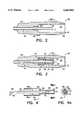
- FIG. 1is a broken longitudinal cross sectional view of the fully assembled needle assembly of the invention
- FIG. 2is a broken longitudinal cross sectional view of the cannula and cannula hub prior to assembly;
- FIG. 3is a view similar to FIG. 2 but in a stage of partial assembly
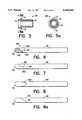
- FIG. 4is a broken longitudinal cross sectional view of the stylet and stylet hub prior to assembly
- FIG. 4ais a cross sectional view along the line A--A in FIG. 4;
- FIG. 5is a side elevation view of the flanged cylindrical member with keyway
- FIG. 5ais a cross sectional view along line A--A in FIG. 5;
- FIG. 6is an enlarged broken longitudinal cross sectional view of an alternate embodiment of the stylet
- FIG. 7is an enlarged broken longitudinal cross sectional view of a second alternate embodiment of the stylet.
- FIG. 8is an enlarged broken top view of a third alternate embodiment of the stylet.
- FIG. 8ais an enlarged broken longitudinal cross sectional view of the stylet of FIG. 8;
- FIG. 9is a broken longitudinal cross sectional view of the distal end of the needle assembly during a first stage of insertion into a schematic representation of the epidural space;
- FIG. 9ais a broken longitudinal cross sectional view of the proximal end of the needle assembly in during the first stage of insertion showing the position of the stylet hub window relative to the indicator rings;
- FIG. 10is a view similar to FIG. 9 but showing the needle assembly in the second stage of insertion with the distal end of the stylet in the epidural space;
- FIG. 10ais a view similar to FIG. 9a but showing the position of the stylet hub window relative to the indicator rings when the needle is in the second stage of insertion;
- FIG. 10bis a view similar to FIG. 10 showing the insertion of a catheter through the stylet.
- the needle assembly 10includes a hollow cannula 12 having a sharpened distal end 14 and a proximal portion 16 which is preferably insert molded in a transparent hollow cannula hub 18.
- the proximal end 17 of the cannulaextends approximately half way into the hollow interior 20 of the cannula hub 18.
- a cylindrical spacer 22 having a distal annular flange 24is inserted over the proximal end 17 of the cannula 12 until the distal flange 24 abuts the distal annular base 26 of the hollow interior 20 of the cannula hub 18.
- a second indicator ring 32 having a second pigmentation, preferably pink or red, indicating an unsafe conditionis press fit over the proximal end 17 of the cannula 12 and abuts the first indicator ring 28.
- the spacer 22 and the indicator rings 28, 32have substantially the same outer diameter and align to form an annular space 34 between them and the interior wall 36 of the hollow cannula hub 18.
- the proximal end 38 of the cannula base 18has exterior threads 40 and a lower proximally extending key portion 42.
- the outer surface of the cannula hub 18is preferably provided with a ridged finger gripping surface 44 and an indicator marking 46 for indicating the angular position of the cannula hub 18 relative to the longitudinal axis of the cannula 12.
- a hollow stylet 48has a blunt distal end 50 and a proximal end 52 which is insert molded in a hollow stylet hub 54.
- the stylet 48extends through the cannula 12 so that the blunt distal end 50 of the stylet 48 extends beyond the sharpened distal end 14 of the cannula 12.
- the stylet hub 54has a stepped profile with a wide distal sleeve portion 56 and narrower proximal keyed portion 58 defining an exterior spring seat 60 therebetween.
- the proximal keyed portion 58 of the stylet hub 54has a tab key 62 extending radially outward therefrom and an interior fluid and catheter throughbore 63 in fluid communication with the interior of the stylet 48.
- the distal sleeve portion 56 of the stylet hub 54is dimensioned to fit in the annular space 34 formed by the cylindrical spacer 22 and indicator rings 28, 32 in the hollow interior 20 of the cannula hub 18.
- the sleeve portion 56is substantially opaque except for a transparent window portion 64.
- the window portion 64may be simply formed by molding, or by cutting away side walls of the sleeve portion 56 while maintaining at least two webs 56a, 56b in the side wall as shown in FIG. 4.
- a coil spring 66is placed over the narrower proximal keyed portion 58 and abuts the external spring seat 60.
- a distally flanged cylindrical member 68 having a keyway 70 and an interior spring seat 72is inserted into the proximal end 38 of the cannula hub 18 and engages the proximal end of the coil spring 66 with its interior spring seat 72.
- the distal flange 74 of the cylindrical member 68is provided with a notch 76 (seen best in FIG. 5a described below) which engages the key portion 42 of the cannula hub 18 and locates the keyway 70 relative to the indicator marking 46 on the surface of the cannula hub 18.
- a sealing O-ring 78is placed over the proximal end of the distally flanged cylindrical member 68 and abuts its distal flange 74.
- a hollow screw cap 80 having distal interior threads 82, an interior seat 84 and a proximal luer coupling 86is screwed onto the proximal exterior threads 40 of the cannula hub 18 and engages the proximal side of the O-ring 78 and presses it against the distal flange 74 of the distally flanged cylinder 68.
- the luer coupling 86permits a syringe to be coupled to the proximal end of the needle assembly so that a loss of resistance technique can be utilized.
- the stylet 48is biased in the distal direction so that its blunt distal end 50 is biased to a position distal of the sharp distal end 14 of the cannula 12 and that the stylet 48 is movable against the force of the coil spring 66 in the proximal direction.
- the dimensions of the parts described aboveare such that when the stylet 48 is moved in the proximal direction against the force of the coil spring 66, the sharp distal end 14 of the cannula 12 is exposed so that the cannula may puncture dense tissue.
- the window portion 64 of the stylet hub 54overlies the first indicator ring 28 and that when the stylet 48 is in the position where it exposes the distal end 14 of the cannula 12, the window portion 64 of the stylet hub 54 overlies the second indicator ring 32.
- a fluid and catheter pathis established between the proximal luer coupling 86 and the hollow interior of the stylet 48 through the through bore 63 in the stylet hub 54. The fluid and catheter path permits the needle assembly to be used in conjunction with a syringe without requiring removal of parts, and also permits a catheter to be inserted therethrough.
- the distal end of the stylet 48is provided with a radial opening 88 and an interior deflection surface 90 in the vicinity of the radial opening 88.
- the purpose of the deflecting surface 90 and the radial opening 88is so that a catheter which is inserted into the luer coupling will travel freely through the hollow stylet to the deflection surface and be deflected to exit through the radial opening in the distal end of the stylet at an angle relative to the longitudinal axis of the stylet as shown and described in more detail below with reference to FIG. 10b.
- the radial opening 88is positioned on the surface of the stylet relative to the key 62 on the stylet hub 54 so that the position of the key 62 indicates the direction of the radial opening 88.
- the position indicator 46is located on the cannula hub 18 relative to the cannula hub key 42 which engages the cylindrical member 68 which carries the stylet hub keyway 70. From the foregoing, those skilled in the art will appreciate that the indicator marking 46 on the cannula hub 18 provides an indication of which direction the radial opening 88 in the stylet is facing and thus which direction a catheter will be deflected when a catheter is inserted through the stylet.
- the distal end of the stylet 48may be filled with a material 190 which will solidify and stick to the interior of the stylet 48.
- a material 190which will solidify and stick to the interior of the stylet 48.
- Such materialsmay include epoxy, solder, or the like.
- the materialis preferably applied so that it solidifies with an inclined proximal surface 192.
- a side portion 188 of the styletis ground away to form both the radial opening 88 and the deflecting surface 90.
- the radial opening 88could be formed prior to introduction of the solidifying material.
- FIG. 7Another way of forming the deflecting surface is shown in FIG. 7.
- a radial indentation 290is made in the wall of the stylet approximately 180 degrees apart from the radial opening 88 to create a deflecting surface 90.
- the indentationis made just proximal the radial opening.
- FIGS. 8 and 8aYet a third way of forming the deflecting surface and the radial opening is shown in FIGS. 8 and 8a.
- a semi-circular or semi-elliptical cut 390is made in the surface of the stylet 48 as shown in FIG. 8 to create a tongue which is depressed into the interior of the stylus as shown in FIG. 8a.
- the outer surface of the tonguebecomes the deflecting surface 90 and the opening from which the tongue was cut becomes the radial opening 88.
- the needle assembly of the inventionis useful for installing catheters in a narrow space such as the epidural space which lies beneath the ligamentum flavum and above the dura mater. When administering epidural anesthesia, it is critical that the anesthesia catheter be placed properly in the epidural space.
- FIGS. 9, 9a, 10, 10a, and 10bshow schematically how the invention is advantageously used to install an epidural catheter.
- FIGS. 9, 10, and 10bshow schematic views of the epidural space 204 which is bounded on one side by the ligamentum flavum 202 which lies beneath the epidermis and other tissues 200 and on the other side by the dura mater 206.
- the epidural space 204extends narrowly along the axis 208 of the spinal canal (not shown).
- the opaque stylet hub 54is pushed back in the cannula hub 18 so that the clear window 64 in the stylet hub exposes the second (pink) indicator ring 32, thereby indicating that the sharp distal end 14 of the cannula 12 is exposed as shown in FIG. 9a.
- the styletis kept pressed in the proximal position until the sharp distal end 14 enters the epidural space 204.
- the blunt end 50 of the stylet 48blocks the hollow interior of the cannula 12 so that it does not become clogged tissue.
- the radial opening 88 in the stylet 48is covered by the cannula 12 and is not clogged with tissue.
- the styletWhen the sharp distal end 14 enters the epidural space 204, the stylet is biased by the coil spring into the space 204 as shown in FIG. 10. Simultaneously, the styler hub 54 moves distally to the position shown in FIG. 10a where the window 64 in the stylet hub 54 exposes the first (green) indicator ring 28. The green indicator now indicates that the radial opening 88 in the stylet 48 lies within the epidural space 48. Further advancement of the needle assembly toward the dura mater 206 is possible, but when the blunt tip 50 of the stylet 48 reaches the dura mater, the stylet will be pushed proximally, and the indicator in the cannula hub will begin to show pink.
- FIG. 10bshows how the distal end 102 of a hollow catheter 100 is deflected by the deflecting surface 90 to exit the stylet 48 through the radial opening 88.
- a needle assemblyfor use in installing a catheter in a direction which is at an angle to the needle assembly. While particular embodiments of the invention have been described, it is not intended that the invention be limited thereto, as it is intended that the invention be as broad in scope as the art will allow and that the specification be read likewise. Thus, while particular deflection surfaces and ways of creating them have been disclosed, it will be appreciated that other deflection surfaces could be utilized. For example, a laser cut-out may be made from the bottom opposite a radial opening, and bent upwards.
Landscapes
- Health & Medical Sciences (AREA)
- Surgery (AREA)
- Life Sciences & Earth Sciences (AREA)
- Heart & Thoracic Surgery (AREA)
- Molecular Biology (AREA)
- Pathology (AREA)
- Engineering & Computer Science (AREA)
- Biomedical Technology (AREA)
- Anesthesiology (AREA)
- Medical Informatics (AREA)
- Nuclear Medicine, Radiotherapy & Molecular Imaging (AREA)
- Animal Behavior & Ethology (AREA)
- General Health & Medical Sciences (AREA)
- Public Health (AREA)
- Veterinary Medicine (AREA)
- Infusion, Injection, And Reservoir Apparatuses (AREA)
- Media Introduction/Drainage Providing Device (AREA)
Abstract
Description
Claims (17)
Priority Applications (2)
| Application Number | Priority Date | Filing Date | Title |
|---|---|---|---|
| US08/223,454US5685852A (en) | 1992-03-30 | 1994-04-05 | Needle assembly and methods useful for epidural anesthesia |
| US08/341,528US5725509A (en) | 1994-04-05 | 1994-11-17 | Air introduction system for medical needles |
Applications Claiming Priority (3)
| Application Number | Priority Date | Filing Date | Title |
|---|---|---|---|
| US07/860,447US5334159A (en) | 1992-03-30 | 1992-03-30 | Thoracentesis needle assembly utilizing check valve |
| US07/949,736US5300046A (en) | 1992-03-30 | 1992-09-23 | Thoracentesis sheath catheter assembly |
| US08/223,454US5685852A (en) | 1992-03-30 | 1994-04-05 | Needle assembly and methods useful for epidural anesthesia |
Related Parent Applications (2)
| Application Number | Title | Priority Date | Filing Date |
|---|---|---|---|
| US07/860,447Continuation-In-PartUS5334159A (en) | 1992-03-30 | 1992-03-30 | Thoracentesis needle assembly utilizing check valve |
| US07/949,736Continuation-In-PartUS5300046A (en) | 1992-03-30 | 1992-09-23 | Thoracentesis sheath catheter assembly |
Related Child Applications (1)
| Application Number | Title | Priority Date | Filing Date |
|---|---|---|---|
| US08/341,528Continuation-In-PartUS5725509A (en) | 1994-04-05 | 1994-11-17 | Air introduction system for medical needles |
Publications (1)
| Publication Number | Publication Date |
|---|---|
| US5685852Atrue US5685852A (en) | 1997-11-11 |
Family
ID=27127571
Family Applications (1)
| Application Number | Title | Priority Date | Filing Date |
|---|---|---|---|
| US08/223,454Expired - LifetimeUS5685852A (en) | 1992-03-30 | 1994-04-05 | Needle assembly and methods useful for epidural anesthesia |
Country Status (1)
| Country | Link |
|---|---|
| US (1) | US5685852A (en) |
Cited By (65)
| Publication number | Priority date | Publication date | Assignee | Title |
|---|---|---|---|---|
| USD408529S (en)* | 1997-12-23 | 1999-04-20 | Fibrasonics Inc. | Cannula for ultrasonic probe |
| USD409746S (en)* | 1997-12-23 | 1999-05-11 | Fibrasonics Inc. | Cannula for an ultrasonic probe |
| US6193692B1 (en)* | 1998-08-03 | 2001-02-27 | Bruce C Harris | Verres needle with high flow adaptor |
| US6228049B1 (en) | 1996-02-09 | 2001-05-08 | Promex, Inc. | Surgical and pharmaceutical site access guide and methods |
| US6270480B1 (en)* | 1998-10-05 | 2001-08-07 | Cancer Technologies, Inc. | Catheter apparatus and method |
| US20030009135A1 (en)* | 2001-07-06 | 2003-01-09 | Fitzgibbons James F. | Epidural space locating device |
| US6613018B2 (en)* | 2001-02-20 | 2003-09-02 | Vita Licensing, Inc. | System and kit for delivery of restorative materials |
| US20040092946A1 (en)* | 2001-02-20 | 2004-05-13 | Bagga Charanpreet S. | System and kit for delivery of restorative materials |
| US20040097830A1 (en)* | 2002-11-20 | 2004-05-20 | David Cooke | Medical instrument |
| US20040097832A1 (en)* | 2002-11-20 | 2004-05-20 | Adams Leland Ray | Medical instrument |
| US6811545B2 (en)* | 2001-01-31 | 2004-11-02 | Vincent L. Vaillancourt | Safety needle |
| WO2007022599A1 (en)* | 2005-08-26 | 2007-03-01 | Novodural Pty Ltd | Improvements relating to epidural administration systems |
| US20070129628A1 (en)* | 2005-12-02 | 2007-06-07 | The Cooper Health System | Regional anesthetic method and apparatus |
| US20070167829A1 (en)* | 2005-12-02 | 2007-07-19 | Robert Hirsh | Regional anesthetic method and apparatus |
| US20070239103A1 (en)* | 2005-12-08 | 2007-10-11 | Hardin David M | Stylet markings |
| US20080047861A1 (en)* | 2006-06-05 | 2008-02-28 | West John H | Product Development and Management Methodologies |
| US20080132926A1 (en)* | 2006-12-01 | 2008-06-05 | Eichmann Stephen E | Devices and methods for accessing the epidural space |
| US20080269638A1 (en)* | 2002-11-20 | 2008-10-30 | Boston Scientific Scimed, Inc. | Medical Instrument |
| US20080287825A1 (en)* | 2007-05-14 | 2008-11-20 | Boston Scientific Scimed, Inc. | Biopsy Device |
| US20090088663A1 (en)* | 2007-10-01 | 2009-04-02 | Miller Michael E | Surgical system |
| US7654735B2 (en) | 2005-11-03 | 2010-02-02 | Covidien Ag | Electronic thermometer |
| US20100069855A1 (en)* | 2008-09-16 | 2010-03-18 | Engineering Resources Group, Inc. | Clog-preventing valved catheter and method of using the catheter |
| US7731692B2 (en) | 2005-07-11 | 2010-06-08 | Covidien Ag | Device for shielding a sharp tip of a cannula and method of using the same |
| EP2226022A1 (en) | 2009-03-04 | 2010-09-08 | Steinbrenner, Marko | Double cannula for local anaesthetic |
| US20100256483A1 (en)* | 2009-04-03 | 2010-10-07 | Insite Medical Technologies, Inc. | Devices and methods for tissue navigation |
| US7828773B2 (en) | 2005-07-11 | 2010-11-09 | Covidien Ag | Safety reset key and needle assembly |
| US7850650B2 (en) | 2005-07-11 | 2010-12-14 | Covidien Ag | Needle safety shield with reset |
| US20110015575A1 (en)* | 2009-07-15 | 2011-01-20 | Thomas Perez | Spinal needle light guide apparatus and method of delivery |
| US7905857B2 (en) | 2005-07-11 | 2011-03-15 | Covidien Ag | Needle assembly including obturator with safety reset |
| US20110125107A1 (en)* | 2007-02-07 | 2011-05-26 | Massachusetts Institute Of Technology | Methods and devices for sensing tissues and tissue compartments |
| US8167947B2 (en) | 2002-12-03 | 2012-05-01 | Trans1 Inc. | Methods for push distraction and for provision of therapy to adjacent motion segments |
| US8277437B2 (en) | 2008-04-02 | 2012-10-02 | Laurimed, Llc | Method of accessing two lateral recesses |
| US8292909B1 (en) | 2010-06-30 | 2012-10-23 | Laurimed, Llc | Devices and methods for cutting tissue |
| WO2012145434A1 (en) | 2011-04-18 | 2012-10-26 | Dr. Py Institute, Llc | Needle with closure and method |
| US8357104B2 (en) | 2007-11-01 | 2013-01-22 | Coviden Lp | Active stylet safety shield |
| US8414587B2 (en) | 2007-01-26 | 2013-04-09 | Laurimed, Llc | Styli used to position device for carrying out selective discetomy |
| US20130131596A1 (en)* | 2006-09-11 | 2013-05-23 | Custom Medical Applications | Neural injection system and related methods |
| WO2013173617A1 (en)* | 2012-05-16 | 2013-11-21 | The Seaberg Company, Inc. | Safety needle |
| EP2695581A1 (en) | 2012-08-07 | 2014-02-12 | Critical Innovations, LLC | Device for simultaneously documenting and treating tension pneumothorax and/or hemothorax |
| US8657842B2 (en) | 2010-06-30 | 2014-02-25 | Laurimed, Llc | Devices and methods for cutting tissue |
| US8808200B2 (en) | 2007-10-01 | 2014-08-19 | Suros Surgical Systems, Inc. | Surgical device and method of using same |
| US8815099B1 (en) | 2014-01-21 | 2014-08-26 | Laurimed, Llc | Devices and methods for filtering and/or collecting tissue |
| US8834417B2 (en) | 2005-06-06 | 2014-09-16 | Covidien Ag | Needle assembly with removable depth stop |
| US20150018798A1 (en)* | 2011-12-30 | 2015-01-15 | Q-Med Ab | Bruiseless cannula |
| US20150265777A1 (en)* | 2014-03-18 | 2015-09-24 | Teleflex Medical Incorporated | Regional anesthesia safety needle device and methods of use |
| WO2015198223A1 (en)* | 2014-06-23 | 2015-12-30 | Omeq Medical Ltd | Identifying a target anatomic location in a subject's body, and delivering a medicinal substance thereto |
| US20160008524A1 (en)* | 2014-07-09 | 2016-01-14 | H&H Medical Corporation | Pneumothorax medical treatment device |
| US20160022312A1 (en)* | 2013-03-01 | 2016-01-28 | The Arizona Board Of Regents On Behalf Of The University Of Arizona | Modified veress needle for tension pneumothorax decompression |
| EP2997913A1 (en)* | 2014-09-18 | 2016-03-23 | AprioMed AB | Medical device |
| US20170135726A1 (en)* | 2015-11-13 | 2017-05-18 | Argon Medical Devices, Inc. | Retractable Centesis Needle |
| US9763731B2 (en) | 2012-02-10 | 2017-09-19 | Myromed, Llc | Vacuum powered rotary devices and methods |
| US9808569B2 (en) | 2006-09-11 | 2017-11-07 | Custom Medical Applications | Neural injection system and related methods |
| US9888940B2 (en) | 2006-09-11 | 2018-02-13 | Custom Medical Applications | Neural injection system and related methods |
| US9951899B2 (en) | 2012-04-17 | 2018-04-24 | Dr. Py Institute, Llc | Self closing connector |
| US9989177B2 (en) | 2012-05-01 | 2018-06-05 | Dr. Py Institute Llc | Device for connecting or filling and method |
| US10046147B2 (en) | 2013-12-26 | 2018-08-14 | Critical Innovations, LLC | Percutaneous access pathway system and method |
| US10117673B2 (en) | 2014-11-21 | 2018-11-06 | Flatmed Llc | Methods and devices for safely positioning a needle syringe in a body cavity |
| US10201655B2 (en) | 2012-08-13 | 2019-02-12 | The Brigham And Women's Hospital, Inc. | Methods and devices for inserting a needle |
| US10286161B2 (en) | 2015-08-20 | 2019-05-14 | Barbara Persons | Integrated needle and cannula for plastic surgery |
| JP2019514546A (en)* | 2016-04-29 | 2019-06-06 | ボシュ・アンド・ロム・インコーポレイテッドBausch & Lomb Incorporated | Ultrasonic surgical aspiration needle assembly having a shaped hub |
| US10351271B2 (en) | 2012-05-01 | 2019-07-16 | Dr. Py Institute Llc | Device for connecting or filling and method |
| US10814119B2 (en) | 2017-09-22 | 2020-10-27 | Critical Innovations, LLC | Percutaneous access pathway system |
| US11033665B2 (en) | 2016-11-04 | 2021-06-15 | The Arizona Board Of Regents On Behalf Of The University Of Arizona | Modified veress needle assembly for tension pneumothorax decompression |
| US11197980B2 (en)* | 2019-11-27 | 2021-12-14 | Skydance Vascular, Inc. | Retractable needle catheter delivery apparatus |
| EP4321116A2 (en) | 2022-08-11 | 2024-02-14 | Critical Innovations, LLC | Percutaneous access pathway system |
Citations (19)
| Publication number | Priority date | Publication date | Assignee | Title |
|---|---|---|---|---|
| US1087845A (en)* | 1913-07-16 | 1914-02-17 | James H Stevens | Salvarsan-needle. |
| US1527291A (en)* | 1923-07-09 | 1925-02-24 | Zorraquin Guillermo | Safety-pressure-indicating needle |
| US2623521A (en)* | 1951-03-12 | 1952-12-30 | Rose Shaw | Indicating stylet needle |
| US2630803A (en)* | 1950-05-12 | 1953-03-10 | Eustachius O Baran | Double pneumothoracic needle |
| US2922420A (en)* | 1957-11-29 | 1960-01-26 | Sierra Eng Co | Epidural needle |
| US4808168A (en)* | 1986-05-05 | 1989-02-28 | Endotherapeutics | Pneumoneedle |
| US4842585A (en)* | 1986-12-18 | 1989-06-27 | B. Braun Melsungen Ag | Steel cannula for spinal and peridural anaesthesia |
| US4869717A (en)* | 1988-04-25 | 1989-09-26 | Adair Edwin Lloyd | Gas insufflation needle with instrument port |
| US5098388A (en)* | 1991-05-02 | 1992-03-24 | Richard Kulkashi | Veress needle assembly |
| US5100390A (en)* | 1990-10-22 | 1992-03-31 | Norma A. Lubeck | Lubeck spinal catheter needle |
| US5104381A (en)* | 1991-08-30 | 1992-04-14 | Origin Medsystems, Inc. | Pneumoneedle with removable stylet assembly |
| US5106376A (en)* | 1989-07-07 | 1992-04-21 | B. Braun Melsungen Ag | Anaesthesia set |
| US5139485A (en)* | 1991-05-03 | 1992-08-18 | Ethicon, Inc. | Verress needle with enhanced acoustical means |
| US5226426A (en)* | 1990-12-18 | 1993-07-13 | Inbae Yoon | Safety penetrating instrument |
| US5256148A (en)* | 1991-05-03 | 1993-10-26 | Ethicon, Inc. | Verress needle with enhanced acoustical means |
| US5322512A (en)* | 1993-05-07 | 1994-06-21 | The Kendall Company | Splittable needle for epidural anesthesia |
| US5330488A (en)* | 1993-03-23 | 1994-07-19 | Goldrath Milton H | Verres needle suturing kit |
| US5330444A (en)* | 1992-09-15 | 1994-07-19 | Intertherapy, Inc. | Catheter tip with a low friction lining and method of use |
| US5374252A (en)* | 1991-12-13 | 1994-12-20 | Minnesota Mining And Manufacturing Company | Locking pneumoneedle |
- 1994
- 1994-04-05USUS08/223,454patent/US5685852A/ennot_activeExpired - Lifetime
Patent Citations (19)
| Publication number | Priority date | Publication date | Assignee | Title |
|---|---|---|---|---|
| US1087845A (en)* | 1913-07-16 | 1914-02-17 | James H Stevens | Salvarsan-needle. |
| US1527291A (en)* | 1923-07-09 | 1925-02-24 | Zorraquin Guillermo | Safety-pressure-indicating needle |
| US2630803A (en)* | 1950-05-12 | 1953-03-10 | Eustachius O Baran | Double pneumothoracic needle |
| US2623521A (en)* | 1951-03-12 | 1952-12-30 | Rose Shaw | Indicating stylet needle |
| US2922420A (en)* | 1957-11-29 | 1960-01-26 | Sierra Eng Co | Epidural needle |
| US4808168A (en)* | 1986-05-05 | 1989-02-28 | Endotherapeutics | Pneumoneedle |
| US4842585A (en)* | 1986-12-18 | 1989-06-27 | B. Braun Melsungen Ag | Steel cannula for spinal and peridural anaesthesia |
| US4869717A (en)* | 1988-04-25 | 1989-09-26 | Adair Edwin Lloyd | Gas insufflation needle with instrument port |
| US5106376A (en)* | 1989-07-07 | 1992-04-21 | B. Braun Melsungen Ag | Anaesthesia set |
| US5100390A (en)* | 1990-10-22 | 1992-03-31 | Norma A. Lubeck | Lubeck spinal catheter needle |
| US5226426A (en)* | 1990-12-18 | 1993-07-13 | Inbae Yoon | Safety penetrating instrument |
| US5098388A (en)* | 1991-05-02 | 1992-03-24 | Richard Kulkashi | Veress needle assembly |
| US5139485A (en)* | 1991-05-03 | 1992-08-18 | Ethicon, Inc. | Verress needle with enhanced acoustical means |
| US5256148A (en)* | 1991-05-03 | 1993-10-26 | Ethicon, Inc. | Verress needle with enhanced acoustical means |
| US5104381A (en)* | 1991-08-30 | 1992-04-14 | Origin Medsystems, Inc. | Pneumoneedle with removable stylet assembly |
| US5374252A (en)* | 1991-12-13 | 1994-12-20 | Minnesota Mining And Manufacturing Company | Locking pneumoneedle |
| US5330444A (en)* | 1992-09-15 | 1994-07-19 | Intertherapy, Inc. | Catheter tip with a low friction lining and method of use |
| US5330488A (en)* | 1993-03-23 | 1994-07-19 | Goldrath Milton H | Verres needle suturing kit |
| US5322512A (en)* | 1993-05-07 | 1994-06-21 | The Kendall Company | Splittable needle for epidural anesthesia |
Cited By (134)
| Publication number | Priority date | Publication date | Assignee | Title |
|---|---|---|---|---|
| US6228049B1 (en) | 1996-02-09 | 2001-05-08 | Promex, Inc. | Surgical and pharmaceutical site access guide and methods |
| USRE42049E1 (en)* | 1996-02-09 | 2011-01-18 | Promex Technologies, Llc | Surgical and pharmaceutical site access guide |
| USD408529S (en)* | 1997-12-23 | 1999-04-20 | Fibrasonics Inc. | Cannula for ultrasonic probe |
| USD409746S (en)* | 1997-12-23 | 1999-05-11 | Fibrasonics Inc. | Cannula for an ultrasonic probe |
| US6193692B1 (en)* | 1998-08-03 | 2001-02-27 | Bruce C Harris | Verres needle with high flow adaptor |
| US6270480B1 (en)* | 1998-10-05 | 2001-08-07 | Cancer Technologies, Inc. | Catheter apparatus and method |
| US6811545B2 (en)* | 2001-01-31 | 2004-11-02 | Vincent L. Vaillancourt | Safety needle |
| US7544196B2 (en) | 2001-02-20 | 2009-06-09 | Orthovita, Inc. | System and kit for delivery of restorative materials |
| US6613018B2 (en)* | 2001-02-20 | 2003-09-02 | Vita Licensing, Inc. | System and kit for delivery of restorative materials |
| US20040092946A1 (en)* | 2001-02-20 | 2004-05-13 | Bagga Charanpreet S. | System and kit for delivery of restorative materials |
| US20030009135A1 (en)* | 2001-07-06 | 2003-01-09 | Fitzgibbons James F. | Epidural space locating device |
| US6773417B2 (en)* | 2001-07-06 | 2004-08-10 | Ispg, Inc. | Epidural space locating device |
| US8088080B2 (en) | 2002-11-20 | 2012-01-03 | Boston Scientific Scimed, Inc. | Medical instrument |
| US7022085B2 (en)* | 2002-11-20 | 2006-04-04 | Scimed Life Systems, Inc. | Medical instrument |
| US20060116604A1 (en)* | 2002-11-20 | 2006-06-01 | Adams Leland R | Medical instrument |
| US20090069713A1 (en)* | 2002-11-20 | 2009-03-12 | Boston Scientific Scimed, Inc. | Medical Instrument |
| US8137288B2 (en) | 2002-11-20 | 2012-03-20 | Boston Scientific Scimed, Inc. | Medical instrument |
| US7008382B2 (en)* | 2002-11-20 | 2006-03-07 | Scimed Life Systems, Inc. | Medical instrument |
| US8043228B2 (en) | 2002-11-20 | 2011-10-25 | Boston Scientific Scimed, Inc. | Medical instrument |
| US8562543B2 (en) | 2002-11-20 | 2013-10-22 | Boston Scientific Scimed, Inc. | Medical instrument |
| US8523783B2 (en) | 2002-11-20 | 2013-09-03 | Boston Scientific Scimed, Inc. | Medical instrument |
| US20040097832A1 (en)* | 2002-11-20 | 2004-05-20 | Adams Leland Ray | Medical instrument |
| US20080269638A1 (en)* | 2002-11-20 | 2008-10-30 | Boston Scientific Scimed, Inc. | Medical Instrument |
| US7449000B2 (en) | 2002-11-20 | 2008-11-11 | Boston Scientific Scimed, Inc. | Medical instrument |
| US20040097830A1 (en)* | 2002-11-20 | 2004-05-20 | David Cooke | Medical instrument |
| US8167947B2 (en) | 2002-12-03 | 2012-05-01 | Trans1 Inc. | Methods for push distraction and for provision of therapy to adjacent motion segments |
| US8328847B2 (en) | 2002-12-03 | 2012-12-11 | Trans1 Inc. | Assemblies for provision of therapy to motion segments |
| US8523918B2 (en) | 2002-12-03 | 2013-09-03 | Baxano Surgical, Inc. | Therapy to adjacent motion segments |
| US8834417B2 (en) | 2005-06-06 | 2014-09-16 | Covidien Ag | Needle assembly with removable depth stop |
| US8348894B2 (en) | 2005-07-11 | 2013-01-08 | Covidien Lp | Needle assembly including obturator with safety reset |
| US7905857B2 (en) | 2005-07-11 | 2011-03-15 | Covidien Ag | Needle assembly including obturator with safety reset |
| US7976498B2 (en) | 2005-07-11 | 2011-07-12 | Tyco Healthcare Group Lp | Needle assembly including obturator with safety reset |
| US7731692B2 (en) | 2005-07-11 | 2010-06-08 | Covidien Ag | Device for shielding a sharp tip of a cannula and method of using the same |
| US8419687B2 (en) | 2005-07-11 | 2013-04-16 | Covidien Ag | Device for shielding a sharp tip of a cannula and method of using the same |
| US8523809B2 (en) | 2005-07-11 | 2013-09-03 | Covidien Ag | Device for shielding a sharp tip of a cannula and method of using the same |
| US7828773B2 (en) | 2005-07-11 | 2010-11-09 | Covidien Ag | Safety reset key and needle assembly |
| US7850650B2 (en) | 2005-07-11 | 2010-12-14 | Covidien Ag | Needle safety shield with reset |
| US8162889B2 (en) | 2005-07-11 | 2012-04-24 | Covidien Ag | Safety reset key and needle assembly |
| WO2007022599A1 (en)* | 2005-08-26 | 2007-03-01 | Novodural Pty Ltd | Improvements relating to epidural administration systems |
| US7654735B2 (en) | 2005-11-03 | 2010-02-02 | Covidien Ag | Electronic thermometer |
| US20070167829A1 (en)* | 2005-12-02 | 2007-07-19 | Robert Hirsh | Regional anesthetic method and apparatus |
| US7645238B2 (en)* | 2005-12-02 | 2010-01-12 | The Cooper Health System | Regional anesthetic method and apparatus |
| US20070129628A1 (en)* | 2005-12-02 | 2007-06-07 | The Cooper Health System | Regional anesthetic method and apparatus |
| US7931594B2 (en)* | 2005-12-02 | 2011-04-26 | The Cooper Health System | Regional anesthetic method and apparatus |
| US20070239103A1 (en)* | 2005-12-08 | 2007-10-11 | Hardin David M | Stylet markings |
| US20080047861A1 (en)* | 2006-06-05 | 2008-02-28 | West John H | Product Development and Management Methodologies |
| US9302072B2 (en)* | 2006-09-11 | 2016-04-05 | Custom Medical Applications | Neural injection system and related methods |
| US20150025504A1 (en)* | 2006-09-11 | 2015-01-22 | Custom Medical Applications | Neural injection system and related methods |
| US20130131596A1 (en)* | 2006-09-11 | 2013-05-23 | Custom Medical Applications | Neural injection system and related methods |
| US9888940B2 (en) | 2006-09-11 | 2018-02-13 | Custom Medical Applications | Neural injection system and related methods |
| US9808569B2 (en) | 2006-09-11 | 2017-11-07 | Custom Medical Applications | Neural injection system and related methods |
| US8882712B2 (en)* | 2006-09-11 | 2014-11-11 | Custom Medical Applications | Neural injection system and related methods |
| US20110218518A1 (en)* | 2006-12-01 | 2011-09-08 | Eichmann Stephen E | Devices and methods for accessing the epidural space |
| US7922738B2 (en) | 2006-12-01 | 2011-04-12 | Insite Medical Technologies, Inc. | Devices and methods for accessing the epidural space |
| EP2094339A4 (en)* | 2006-12-01 | 2012-10-17 | Univ Leland Stanford Junior | DEVICES AND METHODS OF ACCESSING THE EPIDURAL ROOM |
| JP2010511442A (en)* | 2006-12-01 | 2010-04-15 | ザ ボード オブ トラスティーズ オブ ザ リーランド スタンフォード ジュニア ユニバーシティ | Devices and methods for accessing the epidural space |
| US20080132926A1 (en)* | 2006-12-01 | 2008-06-05 | Eichmann Stephen E | Devices and methods for accessing the epidural space |
| WO2008070588A3 (en)* | 2006-12-01 | 2008-09-18 | Univ Leland Stanford Junior | Devices and methods for accessing the epidural space |
| US8414587B2 (en) | 2007-01-26 | 2013-04-09 | Laurimed, Llc | Styli used to position device for carrying out selective discetomy |
| US8920388B2 (en)* | 2007-02-07 | 2014-12-30 | Massachusetts Institute Of Technology | Methods and devices for sensing tissues and tissue compartments |
| US9931477B2 (en) | 2007-02-07 | 2018-04-03 | The Brigham And Women's Hospital, Inc. | Methods and devices for sensing tissues and tissue compartments |
| US20110125107A1 (en)* | 2007-02-07 | 2011-05-26 | Massachusetts Institute Of Technology | Methods and devices for sensing tissues and tissue compartments |
| US20080287825A1 (en)* | 2007-05-14 | 2008-11-20 | Boston Scientific Scimed, Inc. | Biopsy Device |
| US8137287B2 (en) | 2007-05-14 | 2012-03-20 | Boston Scientific Scimed, Inc. | Biopsy device |
| US8202229B2 (en) | 2007-10-01 | 2012-06-19 | Suros Surgical Systems, Inc. | Surgical device |
| US20090088663A1 (en)* | 2007-10-01 | 2009-04-02 | Miller Michael E | Surgical system |
| US8187204B2 (en) | 2007-10-01 | 2012-05-29 | Suros Surgical Systems, Inc. | Surgical device and method for using same |
| US8808200B2 (en) | 2007-10-01 | 2014-08-19 | Suros Surgical Systems, Inc. | Surgical device and method of using same |
| US8357104B2 (en) | 2007-11-01 | 2013-01-22 | Coviden Lp | Active stylet safety shield |
| US8277437B2 (en) | 2008-04-02 | 2012-10-02 | Laurimed, Llc | Method of accessing two lateral recesses |
| US8512291B2 (en)* | 2008-09-16 | 2013-08-20 | Engineering Resources Group, Inc. | Clog-preventing valved catheter and method of using the catheter |
| US20100069855A1 (en)* | 2008-09-16 | 2010-03-18 | Engineering Resources Group, Inc. | Clog-preventing valved catheter and method of using the catheter |
| US20130303998A1 (en)* | 2008-09-16 | 2013-11-14 | Christopher D. Ross | Clog-preventing valved catheter and method of using the catheter |
| US9486609B2 (en)* | 2008-09-16 | 2016-11-08 | Christopher D. Ross | Clog-preventing valved catheter and method of using the catheter |
| EP2226022A1 (en) | 2009-03-04 | 2010-09-08 | Steinbrenner, Marko | Double cannula for local anaesthetic |
| US20100256483A1 (en)* | 2009-04-03 | 2010-10-07 | Insite Medical Technologies, Inc. | Devices and methods for tissue navigation |
| US20110015575A1 (en)* | 2009-07-15 | 2011-01-20 | Thomas Perez | Spinal needle light guide apparatus and method of delivery |
| US8298254B2 (en) | 2010-06-30 | 2012-10-30 | Laurimed, Llc | Devices and methods for cutting and evacuating tissue |
| US8685052B2 (en) | 2010-06-30 | 2014-04-01 | Laurimed, Llc | Devices and methods for cutting tissue |
| US8840632B2 (en) | 2010-06-30 | 2014-09-23 | Laurimed, Llc | Devices and methods for cutting tissue |
| US8657842B2 (en) | 2010-06-30 | 2014-02-25 | Laurimed, Llc | Devices and methods for cutting tissue |
| US8882793B2 (en) | 2010-06-30 | 2014-11-11 | Laurimed, Llc | Devices and methods for cutting tissue |
| US8292909B1 (en) | 2010-06-30 | 2012-10-23 | Laurimed, Llc | Devices and methods for cutting tissue |
| US9532796B2 (en) | 2010-06-30 | 2017-01-03 | Myromed, Llc | Devices and methods for cutting tissue |
| CN103608057B (en)* | 2011-04-18 | 2016-10-12 | 皮博士研究所有限责任公司 | There is pin and the method for closure member |
| US20220219843A1 (en)* | 2011-04-18 | 2022-07-14 | Dr. Py Institute, Llc | Needle with closure and method |
| US12097984B2 (en)* | 2011-04-18 | 2024-09-24 | Dr. Py Institute Llc | Needle with closure and method |
| CN103608057A (en)* | 2011-04-18 | 2014-02-26 | 皮博士研究所有限责任公司 | Needle with closure and method |
| EP2699295A4 (en)* | 2011-04-18 | 2015-01-14 | Py Inst Llc Dr | NEEDLE WITH CLOSURE AND ASSOCIATED METHOD |
| WO2012145434A1 (en) | 2011-04-18 | 2012-10-26 | Dr. Py Institute, Llc | Needle with closure and method |
| US10166346B2 (en)* | 2011-12-30 | 2019-01-01 | Q-Med Ab | Bruiseless cannula |
| US20150018798A1 (en)* | 2011-12-30 | 2015-01-15 | Q-Med Ab | Bruiseless cannula |
| US9770289B2 (en) | 2012-02-10 | 2017-09-26 | Myromed, Llc | Vacuum powered rotary devices and methods |
| US9763731B2 (en) | 2012-02-10 | 2017-09-19 | Myromed, Llc | Vacuum powered rotary devices and methods |
| US9951899B2 (en) | 2012-04-17 | 2018-04-24 | Dr. Py Institute, Llc | Self closing connector |
| US10351271B2 (en) | 2012-05-01 | 2019-07-16 | Dr. Py Institute Llc | Device for connecting or filling and method |
| US9989177B2 (en) | 2012-05-01 | 2018-06-05 | Dr. Py Institute Llc | Device for connecting or filling and method |
| WO2013173617A1 (en)* | 2012-05-16 | 2013-11-21 | The Seaberg Company, Inc. | Safety needle |
| US9072823B2 (en) | 2012-05-16 | 2015-07-07 | The Seaberg Company, Inc. | Safety needle |
| US12419999B2 (en) | 2012-08-07 | 2025-09-23 | Critical Innovations, LLC | Method and device for simultaneously documenting and treating tension pneumothorax and/or hemothorax |
| US9616203B2 (en) | 2012-08-07 | 2017-04-11 | Critical Innovations, LLC | Method and device for simultaneously documenting and treating tension pneumothorax and/or hemothorax |
| EP2695581A1 (en) | 2012-08-07 | 2014-02-12 | Critical Innovations, LLC | Device for simultaneously documenting and treating tension pneumothorax and/or hemothorax |
| US11364326B2 (en)* | 2012-08-07 | 2022-06-21 | Critical Innovations, LLC | Method and device for simultaneously documenting and treating tension pneumothorax and/or hemothorax |
| US12005165B2 (en) | 2012-08-07 | 2024-06-11 | Critical Innovations, LLC | Method and device for simultaneously documenting and treating tension pneumothorax and/or hemothorax |
| US10314952B2 (en) | 2012-08-07 | 2019-06-11 | Critical Innovations, LLC | Method and device for simultaneously documenting and treating tension pneumothorax and/or hemothorax |
| US10201655B2 (en) | 2012-08-13 | 2019-02-12 | The Brigham And Women's Hospital, Inc. | Methods and devices for inserting a needle |
| US10736663B2 (en)* | 2013-03-01 | 2020-08-11 | The Arizona Board Of Regents On Behalf Of The University Of Arizona | Modified veress needle for tension pneumothorax decompression |
| US20160022312A1 (en)* | 2013-03-01 | 2016-01-28 | The Arizona Board Of Regents On Behalf Of The University Of Arizona | Modified veress needle for tension pneumothorax decompression |
| US10046147B2 (en) | 2013-12-26 | 2018-08-14 | Critical Innovations, LLC | Percutaneous access pathway system and method |
| US10864356B2 (en) | 2013-12-26 | 2020-12-15 | Critical Innovations, LLC | Percutaneous access pathway system and method |
| US11865281B2 (en) | 2013-12-26 | 2024-01-09 | Critical Innovations, LLC | Percutaneous access pathway system and method |
| US12263320B2 (en) | 2013-12-26 | 2025-04-01 | Critical Innovations Llc | Percutaneous access pathway system and method |
| US8815099B1 (en) | 2014-01-21 | 2014-08-26 | Laurimed, Llc | Devices and methods for filtering and/or collecting tissue |
| US20150265777A1 (en)* | 2014-03-18 | 2015-09-24 | Teleflex Medical Incorporated | Regional anesthesia safety needle device and methods of use |
| US10617353B2 (en)* | 2014-06-23 | 2020-04-14 | Omeq Medical Ltd. | Identifying a target anatomic location in a subject's body, and delivering a medicinal substance thereto |
| US20170231563A1 (en)* | 2014-06-23 | 2017-08-17 | Omeq Medical Ltd | Identifying a target anatomic location in a subject's body, and delivering a medicinal substance thereto |
| WO2015198223A1 (en)* | 2014-06-23 | 2015-12-30 | Omeq Medical Ltd | Identifying a target anatomic location in a subject's body, and delivering a medicinal substance thereto |
| US20160008524A1 (en)* | 2014-07-09 | 2016-01-14 | H&H Medical Corporation | Pneumothorax medical treatment device |
| US9919082B2 (en)* | 2014-07-09 | 2018-03-20 | H&H Medical Corporation | Pneumothorax medical treatment device |
| US10758263B2 (en) | 2014-09-18 | 2020-09-01 | Apriomed Ab | Medical device |
| EP2997913A1 (en)* | 2014-09-18 | 2016-03-23 | AprioMed AB | Medical device |
| WO2016041921A1 (en) | 2014-09-18 | 2016-03-24 | Apriomed Ab | Medical device |
| US10117673B2 (en) | 2014-11-21 | 2018-11-06 | Flatmed Llc | Methods and devices for safely positioning a needle syringe in a body cavity |
| US10286161B2 (en) | 2015-08-20 | 2019-05-14 | Barbara Persons | Integrated needle and cannula for plastic surgery |
| US20170135726A1 (en)* | 2015-11-13 | 2017-05-18 | Argon Medical Devices, Inc. | Retractable Centesis Needle |
| US9980747B2 (en)* | 2015-11-13 | 2018-05-29 | Argon Medical Devices, Inc. | Retractable centesis needle |
| JP2019514546A (en)* | 2016-04-29 | 2019-06-06 | ボシュ・アンド・ロム・インコーポレイテッドBausch & Lomb Incorporated | Ultrasonic surgical aspiration needle assembly having a shaped hub |
| US11033665B2 (en) | 2016-11-04 | 2021-06-15 | The Arizona Board Of Regents On Behalf Of The University Of Arizona | Modified veress needle assembly for tension pneumothorax decompression |
| US11406809B2 (en) | 2017-09-22 | 2022-08-09 | Critical Innovations, LLC | Percutaneous access pathway system |
| US12324894B2 (en) | 2017-09-22 | 2025-06-10 | Critical Innovations Llc | Percutaneous access pathway system |
| US10814119B2 (en) | 2017-09-22 | 2020-10-27 | Critical Innovations, LLC | Percutaneous access pathway system |
| US11529498B2 (en) | 2019-11-27 | 2022-12-20 | Skydance Vascular, Inc. | Retractable needle catheter delivery apparatus |
| US11197980B2 (en)* | 2019-11-27 | 2021-12-14 | Skydance Vascular, Inc. | Retractable needle catheter delivery apparatus |
| EP4321116A2 (en) | 2022-08-11 | 2024-02-14 | Critical Innovations, LLC | Percutaneous access pathway system |
Similar Documents
| Publication | Publication Date | Title |
|---|---|---|
| US5685852A (en) | Needle assembly and methods useful for epidural anesthesia | |
| US5846226A (en) | Spinal-epidural administration system | |
| US5100390A (en) | Lubeck spinal catheter needle | |
| DE69227382T2 (en) | Driven trocar | |
| US5232442A (en) | Method and apparatus for inducing anesthesia | |
| US5372588A (en) | Trocar having blunt tip | |
| US5630802A (en) | Device for introducing a catheter into a body cavity | |
| US4940458A (en) | Epidural needle placement system | |
| DE19510455B4 (en) | Surgical instrument for the abrupt insertion of an intraosseous trocar needle | |
| US5591186A (en) | Self-cutting trocar | |
| EP0339945B1 (en) | Gas insufflation needle with instrument port | |
| US6716192B1 (en) | Medical needle having a visibly marked tip | |
| US6135769A (en) | Intraosseous injection system | |
| US4973312A (en) | Method and system for inserting spinal catheters | |
| US5843048A (en) | Epidural catheter needle | |
| JP2787012B2 (en) | Device for adjusting extension length of compound spinal needle-dural needle and method of adjusting the same | |
| DE69831068T2 (en) | DEVICE FOR INTRAOSSAL INSERTING OF A DEVICE, AND AN INFUSION TUBE | |
| CA2118037C (en) | Automatic retractable trocar with safety shield | |
| DE69824968T2 (en) | CATHETER INTRODUCTION DEVICE WITH A RETRACTABLE NEEDLE | |
| US7258694B1 (en) | Medical punch and surgical procedure | |
| US6761726B1 (en) | Method and apparatus for the intraosseous introduction of a device such as an infusion tube | |
| DE69428966T2 (en) | Medical device | |
| US20040015133A1 (en) | Epidural apparatus | |
| DE69030591T2 (en) | Subcutaneous injection | |
| US20060206055A1 (en) | Short-tapered epidural injection needle (ice needle) |
Legal Events
| Date | Code | Title | Description |
|---|---|---|---|
| AS | Assignment | Owner name:SYMBIOSIS CORPORATION, FLORIDA Free format text:ASSIGNMENT OF ASSIGNORS INTEREST;ASSIGNOR:TURKEL, DAVID;REEL/FRAME:008260/0693 Effective date:19961126 Owner name:SYMBIOSIS CORPORATION, FLORIDA Free format text:ASSIGNMENT OF ASSIGNORS INTEREST;ASSIGNOR:SCARFONE, FRANK A.;REEL/FRAME:008262/0023 Effective date:19960903 | |
| STCF | Information on status: patent grant | Free format text:PATENTED CASE | |
| FEPP | Fee payment procedure | Free format text:PAYOR NUMBER ASSIGNED (ORIGINAL EVENT CODE: ASPN); ENTITY STATUS OF PATENT OWNER: LARGE ENTITY | |
| FPAY | Fee payment | Year of fee payment:4 | |
| FEPP | Fee payment procedure | Free format text:PAYER NUMBER DE-ASSIGNED (ORIGINAL EVENT CODE: RMPN); ENTITY STATUS OF PATENT OWNER: LARGE ENTITY Free format text:PAYOR NUMBER ASSIGNED (ORIGINAL EVENT CODE: ASPN); ENTITY STATUS OF PATENT OWNER: LARGE ENTITY | |
| FPAY | Fee payment | Year of fee payment:8 | |
| FPAY | Fee payment | Year of fee payment:12 |