US5685671A - Diamond or CBN fluted center cutting end mill - Google Patents
Diamond or CBN fluted center cutting end millDownload PDFInfo
- Publication number
- US5685671A US5685671AUS08/462,990US46299095AUS5685671AUS 5685671 AUS5685671 AUS 5685671AUS 46299095 AUS46299095 AUS 46299095AUS 5685671 AUS5685671 AUS 5685671A
- Authority
- US
- United States
- Prior art keywords
- mill
- cutting
- cutting end
- side wall
- center
- Prior art date
- Legal status (The legal status is an assumption and is not a legal conclusion. Google has not performed a legal analysis and makes no representation as to the accuracy of the status listed.)
- Expired - Lifetime
Links
- 238000005520cutting processMethods0.000titleclaimsabstractdescription175
- 229910003460diamondInorganic materials0.000titleclaimsabstractdescription120
- 239000010432diamondSubstances0.000titleclaimsabstractdescription119
- 239000000463materialSubstances0.000claimsabstractdescription54
- 210000003462veinAnatomy0.000claimsabstractdescription42
- UONOETXJSWQNOL-UHFFFAOYSA-Ntungsten carbideChemical compound[W+]#[C-]UONOETXJSWQNOL-UHFFFAOYSA-N0.000claimsabstractdescription20
- 238000011065in-situ storageMethods0.000claimsabstractdescription14
- 230000000149penetrating effectEffects0.000claims1
- 229910052582BNInorganic materials0.000abstractdescription6
- PZNSFCLAULLKQX-UHFFFAOYSA-NBoron nitrideChemical compoundN#BPZNSFCLAULLKQX-UHFFFAOYSA-N0.000abstractdescription6
- 238000000034methodMethods0.000description13
- 239000000843powderSubstances0.000description13
- 239000000758substrateSubstances0.000description9
- 238000005553drillingMethods0.000description7
- 239000010955niobiumSubstances0.000description7
- GUCVJGMIXFAOAE-UHFFFAOYSA-Nniobium atomChemical compound[Nb]GUCVJGMIXFAOAE-UHFFFAOYSA-N0.000description7
- 229910017052cobaltInorganic materials0.000description6
- 239000010941cobaltSubstances0.000description6
- GUTLYIVDDKVIGB-UHFFFAOYSA-Ncobalt atomChemical compound[Co]GUTLYIVDDKVIGB-UHFFFAOYSA-N0.000description6
- 229910052751metalInorganic materials0.000description6
- 239000002184metalSubstances0.000description6
- 229910000831SteelInorganic materials0.000description5
- 238000000227grindingMethods0.000description5
- 229910052903pyrophylliteInorganic materials0.000description5
- 239000010959steelSubstances0.000description5
- 238000005245sinteringMethods0.000description4
- KWYUFKZDYYNOTN-UHFFFAOYSA-MPotassium hydroxideChemical compound[OH-].[K+]KWYUFKZDYYNOTN-UHFFFAOYSA-M0.000description3
- 238000003754machiningMethods0.000description3
- 238000003801millingMethods0.000description3
- 239000002245particleSubstances0.000description3
- 150000003839saltsChemical class0.000description3
- 229910000679solderInorganic materials0.000description3
- 230000007704transitionEffects0.000description3
- OKTJSMMVPCPJKN-UHFFFAOYSA-NCarbonChemical compound[C]OKTJSMMVPCPJKN-UHFFFAOYSA-N0.000description2
- XEEYBQQBJWHFJM-UHFFFAOYSA-NIronChemical compound[Fe]XEEYBQQBJWHFJM-UHFFFAOYSA-N0.000description2
- PXHVJJICTQNCMI-UHFFFAOYSA-NNickelChemical compound[Ni]PXHVJJICTQNCMI-UHFFFAOYSA-N0.000description2
- KDLHZDBZIXYQEI-UHFFFAOYSA-NPalladiumChemical compound[Pd]KDLHZDBZIXYQEI-UHFFFAOYSA-N0.000description2
- RTAQQCXQSZGOHL-UHFFFAOYSA-NTitaniumChemical compound[Ti]RTAQQCXQSZGOHL-UHFFFAOYSA-N0.000description2
- 239000003082abrasive agentSubstances0.000description2
- 229910002804graphiteInorganic materials0.000description2
- 239000010439graphiteSubstances0.000description2
- 238000004519manufacturing processMethods0.000description2
- BASFCYQUMIYNBI-UHFFFAOYSA-NplatinumChemical compound[Pt]BASFCYQUMIYNBI-UHFFFAOYSA-N0.000description2
- 239000010936titaniumSubstances0.000description2
- 229910052719titaniumInorganic materials0.000description2
- 229910000975Carbon steelInorganic materials0.000description1
- RYGMFSIKBFXOCR-UHFFFAOYSA-NCopperChemical compound[Cu]RYGMFSIKBFXOCR-UHFFFAOYSA-N0.000description1
- BQCADISMDOOEFD-UHFFFAOYSA-NSilverChemical compound[Ag]BQCADISMDOOEFD-UHFFFAOYSA-N0.000description1
- QCWXUUIWCKQGHC-UHFFFAOYSA-NZirconiumChemical compound[Zr]QCWXUUIWCKQGHC-UHFFFAOYSA-N0.000description1
- 230000002411adverseEffects0.000description1
- 229910045601alloyInorganic materials0.000description1
- 239000000956alloySubstances0.000description1
- 229910052782aluminiumInorganic materials0.000description1
- XAGFODPZIPBFFR-UHFFFAOYSA-NaluminiumChemical compound[Al]XAGFODPZIPBFFR-UHFFFAOYSA-N0.000description1
- 239000011230binding agentSubstances0.000description1
- 239000010962carbon steelSubstances0.000description1
- 239000003054catalystSubstances0.000description1
- 238000006243chemical reactionMethods0.000description1
- 238000005056compactionMethods0.000description1
- 238000010276constructionMethods0.000description1
- 229910052802copperInorganic materials0.000description1
- 239000010949copperSubstances0.000description1
- 230000007423decreaseEffects0.000description1
- 238000010586diagramMethods0.000description1
- 230000002708enhancing effectEffects0.000description1
- PCHJSUWPFVWCPO-UHFFFAOYSA-NgoldChemical compound[Au]PCHJSUWPFVWCPO-UHFFFAOYSA-N0.000description1
- 229910052737goldInorganic materials0.000description1
- 239000010931goldSubstances0.000description1
- 229910052735hafniumInorganic materials0.000description1
- VBJZVLUMGGDVMO-UHFFFAOYSA-Nhafnium atomChemical compound[Hf]VBJZVLUMGGDVMO-UHFFFAOYSA-N0.000description1
- 229910052742ironInorganic materials0.000description1
- 239000003863metallic catalystSubstances0.000description1
- 150000002739metalsChemical class0.000description1
- 239000010445micaSubstances0.000description1
- 229910052618mica groupInorganic materials0.000description1
- 229910052759nickelInorganic materials0.000description1
- 229910052763palladiumInorganic materials0.000description1
- 229910052697platinumInorganic materials0.000description1
- 239000011819refractory materialSubstances0.000description1
- 239000003870refractory metalSubstances0.000description1
- 238000007493shaping processMethods0.000description1
- 229910052709silverInorganic materials0.000description1
- 239000004332silverSubstances0.000description1
- 229910052715tantalumInorganic materials0.000description1
- GUVRBAGPIYLISA-UHFFFAOYSA-Ntantalum atomChemical compound[Ta]GUVRBAGPIYLISA-UHFFFAOYSA-N0.000description1
- 229910052726zirconiumInorganic materials0.000description1
Images


Classifications
- B—PERFORMING OPERATIONS; TRANSPORTING
- B23—MACHINE TOOLS; METAL-WORKING NOT OTHERWISE PROVIDED FOR
- B23C—MILLING
- B23C5/00—Milling-cutters
- B23C5/02—Milling-cutters characterised by the shape of the cutter
- B23C5/10—Shank-type cutters, i.e. with an integral shaft
- B23C5/1081—Shank-type cutters, i.e. with an integral shaft with permanently fixed cutting inserts
- B—PERFORMING OPERATIONS; TRANSPORTING
- B23—MACHINE TOOLS; METAL-WORKING NOT OTHERWISE PROVIDED FOR
- B23C—MILLING
- B23C5/00—Milling-cutters
- B23C5/02—Milling-cutters characterised by the shape of the cutter
- B23C5/10—Shank-type cutters, i.e. with an integral shaft
- B23C5/1009—Ball nose end mills
- B23C5/1018—Ball nose end mills with permanently fixed cutting inserts
- B—PERFORMING OPERATIONS; TRANSPORTING
- B23—MACHINE TOOLS; METAL-WORKING NOT OTHERWISE PROVIDED FOR
- B23B—TURNING; BORING
- B23B2222/00—Materials of tools or workpieces composed of metals, alloys or metal matrices
- B23B2222/28—Details of hard metal, i.e. cemented carbide
- B—PERFORMING OPERATIONS; TRANSPORTING
- B23—MACHINE TOOLS; METAL-WORKING NOT OTHERWISE PROVIDED FOR
- B23B—TURNING; BORING
- B23B2226/00—Materials of tools or workpieces not comprising a metal
- B23B2226/12—Boron nitride
- B23B2226/125—Boron nitride cubic [CBN]
- B—PERFORMING OPERATIONS; TRANSPORTING
- B23—MACHINE TOOLS; METAL-WORKING NOT OTHERWISE PROVIDED FOR
- B23B—TURNING; BORING
- B23B2226/00—Materials of tools or workpieces not comprising a metal
- B23B2226/31—Diamond
- B23B2226/315—Diamond polycrystalline [PCD]
- B—PERFORMING OPERATIONS; TRANSPORTING
- B23—MACHINE TOOLS; METAL-WORKING NOT OTHERWISE PROVIDED FOR
- B23C—MILLING
- B23C2222/00—Materials of tools or workpieces composed of metals, alloys or metal matrices
- B23C2222/28—Details of hard metal, i.e. cemented carbide
- B—PERFORMING OPERATIONS; TRANSPORTING
- B23—MACHINE TOOLS; METAL-WORKING NOT OTHERWISE PROVIDED FOR
- B23C—MILLING
- B23C2226/00—Materials of tools or workpieces not comprising a metal
- B23C2226/12—Boron nitride
- B23C2226/125—Boron nitride cubic [CBN]
- B—PERFORMING OPERATIONS; TRANSPORTING
- B23—MACHINE TOOLS; METAL-WORKING NOT OTHERWISE PROVIDED FOR
- B23C—MILLING
- B23C2226/00—Materials of tools or workpieces not comprising a metal
- B23C2226/31—Diamond
- B23C2226/315—Diamond polycrystalline [PCD]
- Y—GENERAL TAGGING OF NEW TECHNOLOGICAL DEVELOPMENTS; GENERAL TAGGING OF CROSS-SECTIONAL TECHNOLOGIES SPANNING OVER SEVERAL SECTIONS OF THE IPC; TECHNICAL SUBJECTS COVERED BY FORMER USPC CROSS-REFERENCE ART COLLECTIONS [XRACs] AND DIGESTS
- Y10—TECHNICAL SUBJECTS COVERED BY FORMER USPC
- Y10T—TECHNICAL SUBJECTS COVERED BY FORMER US CLASSIFICATION
- Y10T407/00—Cutters, for shaping
- Y10T407/19—Rotary cutting tool
- Y10T407/1904—Composite body of diverse material
- Y—GENERAL TAGGING OF NEW TECHNOLOGICAL DEVELOPMENTS; GENERAL TAGGING OF CROSS-SECTIONAL TECHNOLOGIES SPANNING OVER SEVERAL SECTIONS OF THE IPC; TECHNICAL SUBJECTS COVERED BY FORMER USPC CROSS-REFERENCE ART COLLECTIONS [XRACs] AND DIGESTS
- Y10—TECHNICAL SUBJECTS COVERED BY FORMER USPC
- Y10T—TECHNICAL SUBJECTS COVERED BY FORMER US CLASSIFICATION
- Y10T407/00—Cutters, for shaping
- Y10T407/19—Rotary cutting tool
- Y10T407/1946—Face or end mill
- Y10T407/1948—Face or end mill with cutting edge entirely across end of tool [e.g., router bit, end mill, etc.]
- Y—GENERAL TAGGING OF NEW TECHNOLOGICAL DEVELOPMENTS; GENERAL TAGGING OF CROSS-SECTIONAL TECHNOLOGIES SPANNING OVER SEVERAL SECTIONS OF THE IPC; TECHNICAL SUBJECTS COVERED BY FORMER USPC CROSS-REFERENCE ART COLLECTIONS [XRACs] AND DIGESTS
- Y10—TECHNICAL SUBJECTS COVERED BY FORMER USPC
- Y10T—TECHNICAL SUBJECTS COVERED BY FORMER US CLASSIFICATION
- Y10T407/00—Cutters, for shaping
- Y10T407/19—Rotary cutting tool
- Y10T407/1952—Having peripherally spaced teeth
- Y10T407/1962—Specified tooth shape or spacing
- Y10T407/1964—Arcuate cutting edge
- Y10T407/1966—Helical tooth
- Y—GENERAL TAGGING OF NEW TECHNOLOGICAL DEVELOPMENTS; GENERAL TAGGING OF CROSS-SECTIONAL TECHNOLOGIES SPANNING OVER SEVERAL SECTIONS OF THE IPC; TECHNICAL SUBJECTS COVERED BY FORMER USPC CROSS-REFERENCE ART COLLECTIONS [XRACs] AND DIGESTS
- Y10—TECHNICAL SUBJECTS COVERED BY FORMER USPC
- Y10T—TECHNICAL SUBJECTS COVERED BY FORMER US CLASSIFICATION
- Y10T407/00—Cutters, for shaping
- Y10T407/26—Cutters, for shaping comprising cutting edge bonded to tool shank
- Y—GENERAL TAGGING OF NEW TECHNOLOGICAL DEVELOPMENTS; GENERAL TAGGING OF CROSS-SECTIONAL TECHNOLOGIES SPANNING OVER SEVERAL SECTIONS OF THE IPC; TECHNICAL SUBJECTS COVERED BY FORMER USPC CROSS-REFERENCE ART COLLECTIONS [XRACs] AND DIGESTS
- Y10—TECHNICAL SUBJECTS COVERED BY FORMER USPC
- Y10T—TECHNICAL SUBJECTS COVERED BY FORMER US CLASSIFICATION
- Y10T407/00—Cutters, for shaping
- Y10T407/27—Cutters, for shaping comprising tool of specific chemical composition
- Y—GENERAL TAGGING OF NEW TECHNOLOGICAL DEVELOPMENTS; GENERAL TAGGING OF CROSS-SECTIONAL TECHNOLOGIES SPANNING OVER SEVERAL SECTIONS OF THE IPC; TECHNICAL SUBJECTS COVERED BY FORMER USPC CROSS-REFERENCE ART COLLECTIONS [XRACs] AND DIGESTS
- Y10—TECHNICAL SUBJECTS COVERED BY FORMER USPC
- Y10T—TECHNICAL SUBJECTS COVERED BY FORMER US CLASSIFICATION
- Y10T408/00—Cutting by use of rotating axially moving tool
- Y10T408/78—Tool of specific diverse material
Definitions
- This inventionrelates to rotary cutting tools and more particularly to helically fluted end mills and ball nose end mills with diamond-like cutting edges.
- Helically fluted end and ball nose end millsare commonly used milling tools and are generally required to perform severe machining operations under adverse conditions as well as finishing operations where a fine surface is desire.
- the cutting end of a helically fluted end millfor example, includes at least one cutting edge on the end mill blank.
- the cutting end of a ball nose end millcarries the cutting edge around the hemispherical end of the mill.
- Oppositely directed cutting surfaces positioned at the cutting end of the mill blankare subjected to axial and torsional loads which create demands on the materials used for fabrication of the milling tool.
- the material of the cutting edgeshould be as hard as possible to cut a workpiece and it should also be heat resistant to maintain the cutting edge of the mill at elevated temperatures.
- the material of the body of the mill blankmust be both rigid and tough to resist deflection and to maintain the integrity of the mill under loads while the end mill is being used. The foregoing requirements have resulted in compromises in material selection since hard materials tend to be brittle while tough materials tend to wear quite easily.
- This inventionhas application for other types of rotary cutting tools such as router bits, reamers and taps which may have cutting surfaces on an end face.
- the prior artteaches a combination of materials having the characteristics of hardness and wear-resistance at the cutting surfaces and toughness and rigidity of the body and shaft. It has been previously proposed to form the cutting surfaces of one material and the body and shaft of another. This has resulted in a variety of combinations such as cemented tungsten carbide or diamond inserts or tips on carbon steel or carbide shafts. These combinations while individually useful have a common disadvantage, i.e. the braze connection between the insert or tip and a shaft.
- Tungsten carbidecan be soldered or brazed directly to the steel or shaft.
- diamondmust first be adhered to a carbide substrate which is in turn soldered or brazed to the shaft.
- Diamond particlesare typically formed into a compact or PCD (polycrystalline diamond) disk and bonded to a carbide substrate with a metallic catalyst in a high pressure-high temperature press. At atmospheric pressures, however, the metal which catalyzes the bonding of the diamond particles to each other and to the substrate in the press will also catalyze the conversion of diamond to graphite at temperatures above 700° C. which will cause disintegration of the PCD compact. Accordingly a low temperature solder or braze connection is used to attach the substrate to the shaft.
- the aforementioned diamond disks as well as the diamond insert stud blanks, for example,are fabricated from a tungsten carbide substrate with a diamond layer sintered to a face of a substrate, the diamond layer being composed of polycrystalline material.
- a suitable synthetic polycrystalline diamond layeris manufactured by Megadiamond Industries, Inc., Provo, Utah.
- U.S. Pat. No. 4,527,643describes a cutting element for drilling holes which consists of five cutting edges which are comprised of polycrystalline diamond or the like mounted to a central carbide substrate of similar hard material held by a rotatable shaft which can be inserted into a drilling machine. The polycrystalline material is then supported with respect to torsional forces exerted upon it during drilling.
- U.S. Pat. No. 4,627,503describes a polycrystalline diamond and metal element for use as a cutting element for drilling holes or similar uses.
- the cutting elementcomprises a polycrystalline diamond center portion sandwiched between metal.
- the metal side portionis made from a soft metal having a Young's Modulus less than approximately 45 ⁇ 10 6 and is selected from a group comprising cobalt, nickel, iron, copper, silver, gold, platinum, palladium and alloys of these metals.
- Both of these patentsutilize a braze type bonding element to secure the diamond cutters within a drill blank.
- a low temperature solder or braze connectionis used to attach the substrate to a shaft such as the shaft of a helical twist drill.
- This braze connectionlimits the effective life of such drilling tools since it is softer than either the substrate or the shaft. Thus, the braze becomes the weakest point of the tool construction and the limiting factor in the tool usage.
- U.S. Pat. No. 4,762,445teaches a helically fluted twist drill apparatus in which offset opposed veins of sintered abrasive particulate, such as diamond, are embedded within a drill blank made of a less abrasive material such as carbide.
- the non-aligned veins of abrasive materialthemselves intersect adjacent the point and web of the drill.
- the veins of diamondare 180° opposed across the tip of the helical drill blank.
- the opposing veinsintersect at the center or axis of the helical drill to provide a concentration of diamond at the tip of the twist drill.
- U.S. Pat. No. 4,991,467describes a diamond tipped twist drill for drilling holes in a workpiece.
- a drill blank bodyhas a pair of flutes, each flute including a channel that essentially parallels the flutes. Each channel ends at an aperture formed in the body nearest a cutting end of the drill. Diamond material is pressed into the grooves and through the aperture. Subsequent machining at the cutting end of the drill bit body exposes the diamond at the cutting tip and the diamond adjacent the leading edge of the flutes.
- U.S. Pat. Nos. 5,031,484 and 5,070,748describe an end mill having at least a pair of spiral grooves or flutes in the mill blank side walls. Each groove includes polycrystalline diamond or polycrystalline cubic boron nitride formed along a leading edge of each flute.
- the end mills described by the foregoing patentsdo not have center cutting capabilities.
- the present inventionovercomes the problems of the foregoing prior art by providing, for example, a concentration of diamond on a flute and across the end face of a milling cutter blank.
- a center cutting end millcomprises a cutting end and a base end. Flutes extend from the cutting end toward the base end.
- the end millhas a groove across the cutting end and a groove adjacent to a leading edge of each flute. Each groove is filled with polycrystalline diamond-like material sintered in situ within the groove. The diamond-like material is exposed to form a cutting edge along the leading edge of the diamond-like material extending sufficiently close to the center of the end mill for cutting a workpiece all the way to the center of the end mill.
- the groove in the cutting endmay extend to the center axis of the end mill or may stop short of the center axis of the end mill, leaving a portion of the end mill body exposed at the center of the cutting end.
- the groove extending from the cutting end toward the base endmay be a single groove extending from at least adjacent to the center of the cutting end toward the base end or them may be separate grooves.
- the groovesmay be offset from each other for forming separate cutting edges at the intersection.
- FIG. 1is a perspective view of a fluted ball nose end mill
- FIG. 2is an end view taken at 2--2 of FIG. 1;
- FIG. 3is a side view of a ball nose end mill blank with four helical grooves formed in the flanks and hemispherical end of the blank;
- FIG. 4is an end view taken at 4--4 of FIG. 3;
- FIG. 5is a perspective view of a plunging end mill with diamond or CBN formed in a leading edge of the flutes and diamond formed in a groove formed across the cutting end of the end mill body;
- FIG. 6is a side view of a plunging carbide end mill blank with a pair of helical grooves formed in the flanks of the blank with an additional groove formed across the cutting end of the blank;
- FIG. 7is an end view taken at 7--7 of FIG. 6;
- FIG. 8is a partial side view taken at 8--8 of FIG. 5 illustrating the diamond or PcBN curing rake angle and primary and secondary cutting edge relief angles formed behind the diamond or PcBN cutting edge;
- FIG. 9is an alternative configuration of the polycrystalline diamond or PcBN cutting edge with a parabolic cutting edge relief angle
- FIG. 10Ais a side view of an example of an end mill blank with right hand flutes
- FIG. 10Bis a side view of an example of an end mill blank with left hand flutes
- FIG. 10Cis a side view of an example of a ball nose end mill blank with right hand flutes
- FIG. 10Dis a side view of an example of a ball nose end mill blank with left hand flutes
- FIG. 11Ais a side view of an example of an end mill blank with a variable radius cutting end with right hand flutes
- FIG. 11Bis a side view of an example of a flat ended end mill blank with rounded corners at the cutting end;
- FIG. 11Cis a side view of an example of an end mill blank with a cutting end having an elliptical cutting end;
- FIG. 11Dis a side view of an example of a tapered ball nose end mill blank with a tapered cutting end
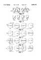
- FIG. 12Ais a top view of a plunging end mill with a diamond or CBN filled groove across the cutting end that passes through the axis of the end mill such that it enables the end mill to be rotated in either direction;
- FIG. 12Bis a top view of an end mill with diamond or CBN across the cutting end of the mill, half of the diamond or CBN is ahead of center for the direction of the cutter rotation.
- FIG. 12Cis a top view of an end mill with the diamond across the cutting end the reverse of FIG. 12B, so that the plunging end mill is rotatable in a counter clock-wise direction;
- FIG. 12Dis a top view of an end mill with diamond or CBN aligned on the axis of the end mill, the diamond covering up to half of the cutting end, the mill being rotatable in either direction;
- FIG. 13Ais a top view of an end mill with diamond or CBN aligned above the axis, the diamond covering up to half the of the cutting end, the end mill being rotatable either clockwise or counter clockwise;
- FIG. 13Bis a top view of an end mill with diamond or CBN aligned below the axis, the diamond covering half the cutting end, the end mill being rotatable either clockwise or counter clockwise;
- FIG. 13Cis a top view of a ball nose end mill with one helical diamond or CBN flute ending at an apex of the mill, the ball nose end mill being rotatable in either direction;
- FIG. 13Dis a top view of a ball nose end mill with a pair of helical diamond flutes connecting at the apex of the ball nose end mill, the mill being rotatable in either direction;
- FIG. 14Ais a top view of a ball nose end mill with four diamond flutes, each flute intersecting at the apex of the ball nose end mill, the mill being rotatable in either direction;
- FIG. 14Bis a top view of a ball nose end mill with a pair of helical flutes that terminate just short of the apex of the ball nose end mill, the mill being rotatable in either direction;
- FIG. 14Cis a top view of an end mill with a pair of diamond flutes that are aligned with the axis of the cutting end of the end mill, each flute ending just short of the axis, the mill being rotatable in either direction;
- FIG. 14Dis a top view of an end mill with a pair of diamond or CBN flutes separated from the axis, each flute being ahead of center such that the mill is rotatable in a clockwise or counter clockwise direction;
- FIG. 15Ais a top view of an end mill with four diamond or CBN flutes separated from the axis, each flute being ahead of center such that the mill is rotatable in a clockwise or counter clockwise direction;
- FIG. 15Bis a top view of an end mill with a single diamond or CBN flute that is aligned with and passes over the axis of the cutting end of the mill, the mill being rotatable in either direction;
- FIG. 15Cis a top view of an end mill with three diamond or CBN flutes disposed radially 120° across the cutting end of the mill, one of the axially aligned flutes passes over the axis, the other pair of flutes terminate just short of the axis, the mill being rotatable in either direction;
- FIG. 15Dis a top view of an end mill with four diamond or CBN flutes across the cutting end of the mill, one of the axially aligned flutes passes over the axis, the other three flutes terminate just short of the axis, the mill being rotatable in either direction;
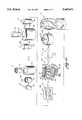
- FIG. 16is a semi-schematic diagram of the process steps involved to fabricate both the end mill and the ball nose end mill cutters.
- FIG. 17illustrates in end view a representative end mill having multiple cutting edges.
- the polycrystalline diamond (CBN) or polycrystalline cubic boron nitride (PcBN) ball nose end mill of FIG. 1generally designated as 10 comprises an end mill body 12 having, for example, four helical flutes 14 circumferentially and equidistantly spaced around the body.
- the body of the ball nose end millmay, for example, be fabricated from a hard and tough material such as cemented tungsten carbide.
- the term "diamond”is used herein interchangeably to denote polycrystalline diamond, polycrystalline cubic boron nitride, or both.
- a groove 18is formed in the leading edge 15 adjacent the flutes 14.
- a sintered polycrystalline diamond or PcBN 30is formed in situ in the helically formed groove 18.
- Cutting edges 32are, for example, ground into the sintered diamond material 30 in the grooves 18 in the end mill body 12.
- the tungsten carbide end mill bodymay then be metallurgically bonded to a steel or carbide shank 16 along a juncture 17.
- the metallurgical bondmay, for example, be a braze.
- the end 13 of the ball nose end mill 10further illustrates the grooves 18 adjacent the leading edge of the flutes 14.
- the polycrystalline diamond or polycrystalline cubic boron nitride 30is compacted and sintered within the grooves 18.
- the flutes 14 and the cutting edge 32are, for example, ground into the PCD or PcBN material after the sintering process is complete (the schematically depicted process of FIG. 16).
- the PCD or PcBN cutting edgecan be formed by methods which include grinding, wire electrical discharge cutting (wire EDM), and electrical discharge grinding (EDG).
- the tungsten carbide end mill body 12is formed with, for example, four helically configured grooves 18 therein.
- the flutes 14are formed in the mill body after the diamond or cbn is sintered within the grooves 18.
- the helically formed grooves 18are, for example, equidistantly spaced around the outer circumferential walls of the body 12 and provide a receptacle for the diamond or cbn powder compacted therein.
- the sides 20 of the helical groove 18preferably transition into a rounded bottom 22 of the groove 18 (FIG. 4). Identical sides 20 are formed in the other grooves 18.
- the reason for the rounded bottom of the grooveis to assure that the polycrystalline diamond or PcBN powder material is packed into the groove without any possibility of voids. If the sides of the groove were not curved to the bottom 22 of the groove, then the sharp 90° corners could cause stress risers and voids in the diamond or PcBN material.
- the end view of the ball nose end millillustrates the merging of the four helically formed diamond veins 18 at the apex of the ball nose end mill body 12.
- This merging of the veins of diamond-like material in the center of the millenable it to be a plunging mill or center cutting mill.
- Such a millmay be driven axially (while rotating) directly into a surface to be milled.
- the center cuttingpermits the mill to form its own hole as it descends.
- Such a center cutting or plunging end millmay be a cylindrical mill with flutes in the side walls or a spherical ball nose end mill. Other shapes are also usable as pointed out hereinafter.
- end millrefers to a mill that can be plunged axially into a workpiece to form its own hole. It may be cylindrical with a flat end face for forming what amounts to a flat bottom hole or if the end of the mill is hemispherical it is referred to as a ball nose end mill. Such mills are not necessarily used only for plunging cuts and are often used as a router or for shaping a profile on a workpiece.
- the grooves 18are compacted with diamond or cbn powder 30 and sintered in a high temperature-high pressure press.
- the polycrystalline diamond or PcBN material 30is formed in situ in the helical grooves 18 of the tungsten carbide body 12.
- the polycrystalline diamondmay be fabricated according to the process in U.S. Pat. No. 4,797,241 which is incorporated herein by reference.
- the end mill bodyis then ground or machined to form the flutes 14. A subsequent grinding process forms the cutting surfaces 32 on the sides and end of the body.
- the plunging end millgenerally designated as 100 comprises an end mill body 112 having, for example, a pair of flutes 114 on opposite sides of the body 112.
- a groove 118is formed in the leading edge 115 of the flutes 114.
- Diamond or cbn powder 130is sintered in the groove 118 and cutting edges 132 are subsequently ground into the sintered diamond.
- a groove 134is further formed across the cutting end of the end mill that has diamond or cbn 130 sintered therein.
- Cutting edges 136are ground in the sintered diamond enabling the end mill to be axially plunged into a workpiece (not shown).
- FIG. 6depicts a tungsten carbide mill body 112 formed with, for example, two helically configured grooves 118 therein.
- the helically formed groovesare equidistantly spaced around the outer circumferential walls of the body 112 and provide a receptacle for the diamond or cbn powder 130 subsequently compacted therein.
- the sides 120 of each groove 118transition into a rounded bottom 122 to assure that the grooves are completely filled with diamond or cbn 130 as was previously described with respect to FIGS. 1 through 4.
- End groove 134intersects each of the grooves 118 and similarly is filled with diamond powder 130.
- FIG. 7is an end view of the mill shown in FIG. 6 illustrating the groove 134 communicating with helical slots 118.
- FIG. 8depicts diamond or cbn cutting edges 132 and 136, the fluted cutter having, for example, a positive top rake angle "A" of about 0° to 25°, preferably 10° to 15°.
- the primary relief area "B” and secondary relief area “C”are angled to provide clearance behind the cutting edges 132 and 136.
- FIG. 9is an alternative embodiment wherein the relief area 238 is parabolic behind diamond cutting edges 230 and 236.
- FIGS. 10A and 10Billustrate end mills 100 with right and left hand flutes 114, respectively.
- FIGS. 10C and 10Ddepict ball nose end mills 10 with left and right hand flutes 14, respectively.
- FIG. 11Ashows an end mill with a variable radius cutting end with right hand flutes.
- FIG. 11Bshows a flat ended end mill with rounded corners and right hand flutes.
- FIG. 11Cis an end mill with an elliptical cutting end with right hand flutes and
- FIG. 11Dillustrates a tapered ball nose end mill with a tapered cutting end and right hand flutes. These can also have left hand flutes.
- Both right and left hand helical flutescan also be either up-shear or down-shear. Both can have a variable and/or multiple taper angle geometry in up-shear or down-shear.
- FIG. 12Ais a view of the cutting end of the plunging end mill 100 with the diamond or cbn material 130 passing through the central axis of the end mill such that the mill may be rotated in either direction as a right or left hand end mill.
- FIG. 12Baligns the diamond 130 to the right of the axis, ahead of the axis for a left hand or right hand helix such that the end mill may only be rotated clockwise.
- FIG. 12Cis the reverse of 12B, hence rotation is counter-clockwise.
- FIG. 12Ddepicts an end mill with a vein of diamond extending generally radially on half the cutting end of the end mill aligned with the axis so that the mill may be rotated in either direction.
- FIG. 13Ais the same as 12D accept that the diamond is positioned behind the axis as the end mill rotates counter clockwise and FIG. 13B is the reverse of 13A with a clockwise rotation. End mills shown in FIGS. 13A and 13B can be rotated in either direction.
- FIG. 13Cis an end view of a ball nose end mill with at least a single helical flute terminating at the apex of the hemispherical.
- FIG. 13Dis a ball nose end mill with a pair of helical flutes.
- FIG. 14Ais a ball nose end mill with four helical flutes, all of which pass through the apex of the hemispherical end, and
- FIG. 14Bis a ball nose end mill with a pair of helical flutes, the ends of which terminate just short of the apex of the ball.
- FIG. 14Cis a center cutting end mill rotatable in either direction with a pair of diamond flutes, the ends of which end short of the axis of the mill.
- FIG. 14Dis the same as 14C except the PCD or PcBN is either ahead of center or behind center according to the direction of rotation.
- FIG. 15Ais the same as 14D except there are four flutes.
- FIGS. 15B through 15Ddepict center cutting end mills with at least one of the radially disposed diamond flutes ending just past the axis of the end mill, the other of the flutes ending just short of the axis of the end mill.
- FIGS. 12 through 15are typical center geometries for the end mills illustrated in FIGS. 10 and 11.
- the groove across the cutting end of the plunging millmay be a single groove extending all the way across a hemispherical end on a ball nose end mill or fluted mill, or may be segmented in a variety of ways as indicated in the embodiments illustrated in the drawings.
- the cutting edgemay have either negative or positive rake, from -10° to +20°, for example, without departing from the scope of this invention.
- One or more flutes or cutting edges of a multiple flute end millmay have diamond-like material.
- a process of forming, for example, a 5/8 inch (16 mm) ball nose end mill cutteris a process of forming, for example, a 5/8 inch (16 mm) ball nose end mill cutter.
- a carbide body having, for example, four flutesis formed slightly oversize (by 3/4 to 2 mm) on all dimensions of the ball nose end mill body.
- the ball nose end millis ground to the proper diameter after the diamond sintering process is completed.
- the ball nose end mill body 12is preferably formed from a cemented tungsten carbide material.
- a helically formed groove 18is formed where each vein of PCD or PcBN is desired with a depth of about 1.25 mm and a width of the groove 18 of about 1.25 mm.
- the sidewalls 20 of the groovetransition into a rounded bottom 22 of the helical groove 18 and a wider opening at the surface of the body.
- the groove 18is so configured to assure that the diamond powder is packed in the groove without voids.
- the diamond-like materialis preferably diamond powder having a size range from 3 to 60 microns. The preferred size range of the powder is from 1 to 50 microns.
- the binder/catalyst for the diamond powderis cobalt.
- a ratio of cobalt to diamondis 5 to 20 percent by volume of cobalt. The percentage of cobalt is preferred to be 10 volume percent.
- the processis similar when forming a PcBN mill except that cubic boron nitride particles are packed in the grooves.
- the grooves of the cemented tungsten carbide blank or body 12are preferably prepared by "breaking" or “dulling” the edges of the grooves. The reason for dulling the edges of the grooves will become apparent with further discussion of the process.
- the mixed diamond powder and cobaltis then packed into the grooves 18.
- the blank 12is then placed in a refractory metal can or receptacle 31.
- a typical refractory materialis selected from the group consisting of zirconium, columbium, tantalum and hafnium.
- the receptacle 31is formed of columbium and placed over the diamond powder pressed in the grooves 18 formed in the blank.
- the carbide blank 12 in the canis then run through a die to fit tightly around the blank.
- a second can 53 of columbium around the first canis run through a die to completely seal the second can 53 over the first can.
- the sealed can containing the blank 12 and now generally designated as 55is then run through a pre-compact stage 56.
- the can 55is first surrounded by salt 57, then is put in a pre-compact press 56 to further compact the subassembly.
- the canis subjected to about 7000 kg/cm 2 in the pre-compact press. This assures that the blank 12 trapped within the columbium cans 50 and 53 is as tightly packed as possible prior to the sintering process.
- the compressed can 55is now ready for the sintering process. The reason the groove edges are dulled is to prevent the columbium cans from being cut during the pre-compaction stage.
- the can 55is loaded into a pyrophyllite cube.
- the cubegenerally designated as 60, is packed with salt rings 57 and lined with a graphite sleeve 66.
- the cube 60is then capped with a titanium disk 65, followed by a mica ring baffle 64 and another titanium disk 63.
- a relatively thick steel ring 62surrounds a pyrophyllite cap 61. Both ends of the pyrophyllite cube have the same assembly, thus closing in the can 55 within the salt rings 57 in the center of the pyrophyllite cube.
- the assembled cube 60then goes to a high pressure-high temperature press 70.
- the cubeis pressed at a temperature of about 1,300° to 1,600° C. at a pressure of about 70,000 kg/cm 2 .
- the total time of the pressis approximately 10 minutes.
- the temperatureis ramped up to 1,500° C. for about four minutes, the cube 60 is held at temperature of 1,500° C. for about one minute and is then allowed to cool down for approximately five minutes.
- polycrystalline diamondis formed in situ in the grooves in the blank.
- An important aspect of this processis that the heat up be relatively slow with a slow cool down period. This is done primarily to reduce residual stresses within the finished ball nose end mill.
- the sintered can 55is subsequently broken out of the pyrophyllite cube 60.
- the sintered ball nose end mill body 12is still housed within the cans 31 and 53 of columbium.
- the enclosed ball nose end mill body 12is immersed in a bath of fused potassium hydroxide to remove the columbium cans.
- the bodyis then brazed to a mill shank 16.
- the body 12 with attached shankis ground to the finished diameter prior to grinding the flutes 14, sintered diamond 30 and relief angles as required.
- a larger press apparatuscould be used to allow a continuous shank to be pressed with formed grooves to eliminate the need for a braze or solder joint.
- the polycrystalline diamondis formed in the grooves, there is shrinkage from the diamond powder packed into the grooves.
- up to about two millimetersmay be ground off the tungsten carbide body to bring its diameter down to the level of the polycrystalline diamond.
- the PCD veinsare in the order of about 1.5 to 2.5 mm wide and one to two millimeters deep.
- the specific configuration of diamond filled grooves on the end face of an end mill or the likedepends on the purpose for which the mill is to be used. For example, different numbers of flutes and cutting edges may be desirable, depending on whether the mill is to be used for rough machining or obtaining a fine finish.
- the material for which the mill is to be usedalso affects the geometry of cutting edges.
- FIGS. 12A, 12B or 12Ca suitable configuration of grooves as illustrated in FIGS. 12A, 12B or 12C may be preferred.
- the PCD materialextends to the center of the end face.
- a configuration as illustrated in FIG. 14C, 14D or 15Amay be preferred.
- a PcBN materialmay be used in the grooves and the PcBN material is formed do not extend quite to the center line of the end face or axis of the mill. At the exact center of the mill, there is essentially a zero surface speed during cutting.
- PCD or PcBN at that locationmay be inadequately supported by cemented tungsten carbide and be subject to breakage.
- a material tougher than PCD or PcBNis preferred.
- the groovesstop short of the center of the face, leaving a center point of cemented tungsten carbide which is appreciably tougher.
- the ends of the groovesmay be only 1/4 mm apart and a small "core" of workpiece between the diamond cutting edges is small and readily bends or breaks over into the areas cut by the diamond-like material.
- FIGS. 12A and 12CAnother groove geometry variable is whether grooves are aligned on a diameter of the end face as illustrated in FIGS. 12A and 12C, or whether the grooves are offset as illustrated in FIGS. 12B, 12C and 14D, for example. More commonly, the cutting edge on a mill is not on a diameter but is offset from the diameter. If the grooves are made and diamond formed in alignment on a diameter, additional diamond must be ground to form the cutting edges which are preferably offset from a diameter. Thus, in such an embodiment an offset configuration of the diamond filled grooves is preferred. Offset of the cutting edge from a diameter decreases the forces imposed during cutting and permits higher speed operation.
- the milltends to wear out first at the "corner" between the side faces of the mill and the end face, i.e., at the intersection between the cylindrical side of the body and the flat end face.
- An end mill as illustrated in FIG. 17is desirable for such a situation.
- the generally cylindrical cemented tungsten carbide body 71has four grooves with veins of PCD or PcBN 72 formed in situ in the side walls.
- the end view of FIG. 17illustrates a blank for forming an end mill before the flutes and cutting edges are ground. The ends of the filled grooves 72 can be seen and it will be understood that the grooves extend helically on the sides of the tungsten carbide body.
- grooves 73across the end face of the end mill blank which are also filled with PCD or PcBN. These grooves are each offset from a diameter and end a short distance from the center of the end face. The grooves on the end face are offset circumferentially 45° from the grooves on the side of the end mill blank.
- the flutes and cutting edgesare ground into the body, there are four cutting edges formed at the "corner" by the four grooves 72 in the side wall and an additional four cutting edges where the end face grooves 73 reach the corner.
- veins of diamond in the end facebe midway between the veins of diamond in the side walls of the mill.
Landscapes
- Engineering & Computer Science (AREA)
- Mechanical Engineering (AREA)
- Milling Processes (AREA)
Abstract
Description
Claims (14)
Priority Applications (3)
| Application Number | Priority Date | Filing Date | Title |
|---|---|---|---|
| US08/462,990US5685671A (en) | 1993-11-01 | 1995-06-01 | Diamond or CBN fluted center cutting end mill |
| US08/859,741US6158304A (en) | 1993-11-01 | 1997-05-21 | Process for forming a center cutting end mill |
| US08/859,742US6152657A (en) | 1993-11-01 | 1997-05-21 | Center cutting end mill |
Applications Claiming Priority (2)
| Application Number | Priority Date | Filing Date | Title |
|---|---|---|---|
| US14667993A | 1993-11-01 | 1993-11-01 | |
| US08/462,990US5685671A (en) | 1993-11-01 | 1995-06-01 | Diamond or CBN fluted center cutting end mill |
Related Parent Applications (1)
| Application Number | Title | Priority Date | Filing Date |
|---|---|---|---|
| US14667993AContinuation-In-Part | 1993-11-01 | 1993-11-01 |
Related Child Applications (2)
| Application Number | Title | Priority Date | Filing Date |
|---|---|---|---|
| US08/859,742DivisionUS6152657A (en) | 1993-11-01 | 1997-05-21 | Center cutting end mill |
| US08/859,741DivisionUS6158304A (en) | 1993-11-01 | 1997-05-21 | Process for forming a center cutting end mill |
Publications (1)
| Publication Number | Publication Date |
|---|---|
| US5685671Atrue US5685671A (en) | 1997-11-11 |
Family
ID=26844178
Family Applications (3)
| Application Number | Title | Priority Date | Filing Date |
|---|---|---|---|
| US08/462,990Expired - LifetimeUS5685671A (en) | 1993-11-01 | 1995-06-01 | Diamond or CBN fluted center cutting end mill |
| US08/859,742Expired - LifetimeUS6152657A (en) | 1993-11-01 | 1997-05-21 | Center cutting end mill |
| US08/859,741Expired - LifetimeUS6158304A (en) | 1993-11-01 | 1997-05-21 | Process for forming a center cutting end mill |
Family Applications After (2)
| Application Number | Title | Priority Date | Filing Date |
|---|---|---|---|
| US08/859,742Expired - LifetimeUS6152657A (en) | 1993-11-01 | 1997-05-21 | Center cutting end mill |
| US08/859,741Expired - LifetimeUS6158304A (en) | 1993-11-01 | 1997-05-21 | Process for forming a center cutting end mill |
Country Status (1)
| Country | Link |
|---|---|
| US (3) | US5685671A (en) |
Cited By (81)
| Publication number | Priority date | Publication date | Assignee | Title |
|---|---|---|---|---|
| US5915888A (en)* | 1997-10-01 | 1999-06-29 | Minicozzi; Alfonso | Rotary cutting tool assembly |
| US5971670A (en)* | 1994-08-29 | 1999-10-26 | Sandvik Ab | Shaft tool with detachable top |
| US6082935A (en)* | 1997-06-13 | 2000-07-04 | Nachi Fujikoshi Corp. | Solid cemented carbide ball nose end mill |
| US6132148A (en)* | 1996-02-15 | 2000-10-17 | Habit Diamond Limited | Machining tool and method for forming same |
| US6152657A (en)* | 1993-11-01 | 2000-11-28 | Smith International, Inc. | Center cutting end mill |
| US6282673B1 (en) | 1997-05-13 | 2001-08-28 | Micron Technology, Inc. | Method of recording information system events |
| US6290438B1 (en)* | 1998-02-19 | 2001-09-18 | August Beck Gmbh & Co. | Reaming tool and process for its production |
| US6338754B1 (en) | 2000-05-31 | 2002-01-15 | Us Synthetic Corporation | Synthetic gasket material |
| US6402787B1 (en) | 2000-01-30 | 2002-06-11 | Bill J. Pope | Prosthetic hip joint having at least one sintered polycrystalline diamond compact articulation surface and substrate surface topographical features in said polycrystalline diamond compact |
| US6425922B1 (en) | 2000-01-30 | 2002-07-30 | Diamicron, Inc. | Prosthetic hip joint having at least one sintered polycrystalline diamond compact articulation surface |
| US6494918B1 (en) | 2000-01-30 | 2002-12-17 | Diamicron, Inc. | Component for a prosthetic joint having a diamond load bearing and articulation surface |
| US6514289B1 (en) | 2000-01-30 | 2003-02-04 | Diamicron, Inc. | Diamond articulation surface for use in a prosthetic joint |
| US6596225B1 (en) | 2000-01-31 | 2003-07-22 | Diamicron, Inc. | Methods for manufacturing a diamond prosthetic joint component |
| EP1342522A1 (en)* | 2002-03-07 | 2003-09-10 | August Beck GmbH & Co. | Guide for a reaming tool |
| US20030180104A1 (en)* | 2002-03-25 | 2003-09-25 | Hitachi Tool Engineering Ltd. | Radius end mill having radius edge enhanced in resistance to chipping and fracture |
| US6652201B2 (en)* | 2000-02-18 | 2003-11-25 | Sumitomo Electric Industries, Ltd. | Ball end mill |
| US6655880B2 (en)* | 2001-02-15 | 2003-12-02 | Macarthur Mike | End mill |
| US6676704B1 (en) | 1994-08-12 | 2004-01-13 | Diamicron, Inc. | Prosthetic joint component having at least one sintered polycrystalline diamond compact articulation surface and substrate surface topographical features in said polycrystalline diamond compact |
| US6709463B1 (en) | 2000-01-30 | 2004-03-23 | Diamicron, Inc. | Prosthetic joint component having at least one solid polycrystalline diamond component |
| US6723277B1 (en)* | 1999-03-20 | 2004-04-20 | Karl Simon Gmbh & Co. Kg | Method for producing a milling disc and milling disc produced according to the inventive method |
| US6793681B1 (en) | 1994-08-12 | 2004-09-21 | Diamicron, Inc. | Prosthetic hip joint having a polycrystalline diamond articulation surface and a plurality of substrate layers |
| US20050084352A1 (en)* | 2002-02-21 | 2005-04-21 | Bernhard Borschert | Rotary cutting tool, such as a drill, comprising an exchangeable cutting insert, and an exchangeable cutting insert |
| US20060072976A1 (en)* | 2004-10-05 | 2006-04-06 | Frota De Souza Ruy | Modular drill |
| US20060239850A1 (en)* | 2005-03-30 | 2006-10-26 | Denboer David | Endmills and method of making the same |
| US20070029116A1 (en)* | 2005-08-03 | 2007-02-08 | Keshavan Madapusi K | High energy cutting elements and bits incorporating the same |
| US20070104551A1 (en)* | 2004-03-03 | 2007-05-10 | Joerg Guehring | Tool for trimming boreholes |
| US20070172321A1 (en)* | 2004-04-20 | 2007-07-26 | Tamotsu Nagai | Ball endmill |
| US20070272330A1 (en)* | 2006-05-11 | 2007-11-29 | Philippe Turcot | Spiral profile cutting tool |
| US7396501B2 (en) | 1994-08-12 | 2008-07-08 | Diamicron, Inc. | Use of gradient layers and stress modifiers to fabricate composite constructs |
| US7396505B2 (en) | 1994-08-12 | 2008-07-08 | Diamicron, Inc. | Use of CoCrMo to augment biocompatibility in polycrystalline diamond compacts |
| US20080247899A1 (en)* | 2007-04-03 | 2008-10-09 | Cho H Sam | Contoured PCD and PCBN for twist drill tips and end mills and methods of forming the same |
| US7494507B2 (en) | 2000-01-30 | 2009-02-24 | Diamicron, Inc. | Articulating diamond-surfaced spinal implants |
| US20090245946A1 (en)* | 2008-03-31 | 2009-10-01 | Sumitomo Electric Hardmetal Corp. | Cubic boron nitride radius end mill |
| US20090252564A1 (en)* | 2006-04-04 | 2009-10-08 | Vladimir Volokh | Face milling cutter |
| WO2010044925A1 (en)* | 2008-10-17 | 2010-04-22 | Precorp, Inc. | Shielded pcd or pcbn cutting tools |
| US20100260559A1 (en)* | 2007-11-07 | 2010-10-14 | Haruhisa Higasayama | Ball end mill |
| US20110020085A1 (en)* | 2009-07-27 | 2011-01-27 | Hilti Aktiengesellschaft | Drill and production method |
| WO2011050053A2 (en) | 2009-10-23 | 2011-04-28 | Kennametal Inc. | Three-dimensional surface shaping of rotary cutting tool edges with lasers |
| US20110154954A1 (en)* | 2009-12-31 | 2011-06-30 | Diamond Innovations, Inc. | Machining tool blank |
| US8327957B2 (en) | 2010-06-24 | 2012-12-11 | Baker Hughes Incorporated | Downhole cutting tool having center beveled mill blade |
| US8434572B2 (en) | 2010-06-24 | 2013-05-07 | Baker Hughes Incorporated | Cutting elements for downhole cutting tools |
| US20130209184A1 (en)* | 2010-06-16 | 2013-08-15 | Element Six Limited | Cutter elements, rotary machine tools comprising same and method for making same |
| WO2013164068A1 (en)* | 2012-05-04 | 2013-11-07 | Hufschmied Zerspanungssysteme Gmbh | Dental milling tool, and milling method for producing dental prosthesis parts |
| US20140119887A1 (en)* | 2012-11-01 | 2014-05-01 | United Technologies Corporation | Fluid-cooled seal arrangement for a gas turbine engine |
| CN104039488A (en)* | 2012-03-29 | 2014-09-10 | 三菱综合材料株式会社 | Ball end mill |
| US8936109B2 (en) | 2010-06-24 | 2015-01-20 | Baker Hughes Incorporated | Cutting elements for cutting tools |
| US9151120B2 (en) | 2012-06-04 | 2015-10-06 | Baker Hughes Incorporated | Face stabilized downhole cutting tool |
| US20150342617A1 (en)* | 2013-01-11 | 2015-12-03 | Nobel Biocare Services Ag | Dental drill bit |
| WO2016008821A1 (en)* | 2014-07-18 | 2016-01-21 | Element Six (Uk) Limited | Method of making super-hard articles |
| JP2016097452A (en)* | 2014-11-18 | 2016-05-30 | 三菱マテリアル株式会社 | End mill |
| US9468980B2 (en) | 2007-04-03 | 2016-10-18 | H. Sam Cho | Contoured PCD and PCBN segments for cutting tools containing such segments |
| US20170106454A1 (en)* | 2014-03-28 | 2017-04-20 | Mitsubishi Materials Corporation | Rotary cutting tool including polycrystalline diamond material |
| US9643282B2 (en) | 2014-10-17 | 2017-05-09 | Kennametal Inc. | Micro end mill and method of manufacturing same |
| USD798922S1 (en) | 2015-10-07 | 2017-10-03 | Kennametal Inc. | Cutting head for rotary drill |
| USD798921S1 (en) | 2015-10-07 | 2017-10-03 | Kennametal Inc. | Cutting head for modular drill |
| IL257313A (en)* | 2018-02-01 | 2018-03-29 | Hanita Metal Works Ltd | Multi-flute end mill |
| JP2018051673A (en)* | 2016-09-28 | 2018-04-05 | 三菱日立ツール株式会社 | Ball end mill |
| US9937567B2 (en) | 2015-10-07 | 2018-04-10 | Kennametal Inc. | Modular drill |
| US10040132B2 (en) | 2015-06-24 | 2018-08-07 | Kennametal Inc. | Rotary tool, in particular a drill for such a rotary tool |
| US10052698B2 (en) | 2013-10-15 | 2018-08-21 | Kennametal Inc. | Modular carrier tool and tool head |
| US10058930B2 (en) | 2013-04-03 | 2018-08-28 | Kennametal Inc. | Tool head for rotary cutting tool and rotary cutting tool including same |
| US10071430B2 (en) | 2015-10-07 | 2018-09-11 | Kennametal Inc. | Cutting head, rotary tool and support for the rotary tool and for the accommodation of the cutting head |
| US10105769B2 (en) | 2014-04-17 | 2018-10-23 | Kennametal Inc. | Machining tool and method for manufacturing a machining tool |
| CN109079157A (en)* | 2018-08-15 | 2018-12-25 | 九江海天设备制造有限公司 | A kind of method of machining high-precision two-wire rectangular coil screw rod |
| US10213845B2 (en) | 2014-04-08 | 2019-02-26 | Kennametal Inc. | Rotary tool, in particular a drill, and a cutting head for said rotary tool |
| CN109396558A (en)* | 2018-09-25 | 2019-03-01 | 广州汇专工具有限公司 | It is a kind of for processing the Diamond Cutting Toolss of hard brittleness difficult-to-machine material |
| WO2019047262A1 (en)* | 2017-09-06 | 2019-03-14 | 深圳市鑫国钰精密工具有限公司 | Circular-nose cutter |
| US10293411B2 (en)* | 2016-11-15 | 2019-05-21 | Sumitomo Electric Hardmetal Corp. | Cutting tool |
| US20190210174A1 (en)* | 2018-01-08 | 2019-07-11 | Ford Motor Company | Tooling assembly with internal coolant passages for machines |
| US10369636B2 (en) | 2014-04-17 | 2019-08-06 | Kennametal Inc. | Machining tool and method for manufacturing a machining tool |
| WO2020035551A1 (en)* | 2018-08-16 | 2020-02-20 | Hartmetall-Werkzeugfabrik Paul Horn Gmbh | Chamfering tool |
| US10702926B2 (en)* | 2016-10-07 | 2020-07-07 | Sumitomo Electric Hardmetal Corp. | Rotary cutting blade material and method for manufacturing the same |
| US10799958B2 (en) | 2017-08-21 | 2020-10-13 | Kennametal Inc. | Modular rotary cutting tool |
| US20210213572A1 (en)* | 2018-05-14 | 2021-07-15 | Ab Sandvik Coromant | Veined tool blank and drill |
| WO2021180530A1 (en)* | 2020-03-10 | 2021-09-16 | Prima Dental Manufacturing Limited | Manufacture of a dental prosthesis |
| JP2021530372A (en)* | 2018-09-25 | 2021-11-11 | 匯専科技集團股▲フン▼有限公司 | Diamond cutting tool for machining hard and brittle difficult-to-cut materials |
| US11193389B2 (en) | 2019-10-18 | 2021-12-07 | Raytheon Technologies Corporation | Fluid cooled seal land for rotational equipment seal assembly |
| US20220266357A1 (en)* | 2019-08-09 | 2022-08-25 | Kamen Petrov Kamenov | Milling bit with spherical ending for cnc milling of industrial clay |
| US11865629B2 (en) | 2021-11-04 | 2024-01-09 | Kennametal Inc. | Rotary cutting tool with high ramp angle capability |
| US11911830B2 (en) | 2019-06-13 | 2024-02-27 | Kennametal India Ltd. | Indexable drilling inserts |
| US12440905B2 (en)* | 2019-08-09 | 2025-10-14 | Kamen Petrov Kamenov | Milling bit with spherical ending for CNC milling of industrial clay |
Families Citing this family (42)
| Publication number | Priority date | Publication date | Assignee | Title |
|---|---|---|---|---|
| KR100291563B1 (en)* | 1998-11-12 | 2001-07-12 | 송호근 | Spherical Turning Tool |
| US6146476A (en)* | 1999-02-08 | 2000-11-14 | Alvord-Polk, Inc. | Laser-clad composite cutting tool and method |
| US6908266B1 (en)* | 2000-10-31 | 2005-06-21 | Eastman Kodak Company | Apparatus for forming a microlens array mold |
| US6527211B1 (en) | 2001-08-07 | 2003-03-04 | Masco Corporation | Blade and spring fiber chopper |
| US6619173B2 (en) | 2001-08-07 | 2003-09-16 | Masco Corporation Taylor | Vibratory fiber chopper |
| US6517017B1 (en) | 2001-08-07 | 2003-02-11 | Masco Corporation | End mill fiber chopper |
| US6874978B2 (en)* | 2002-03-25 | 2005-04-05 | Milwaukee Electric Tool Corporation | Boring bit and methods for manufacturing boring bits |
| US20030190201A1 (en)* | 2002-04-08 | 2003-10-09 | Marusich Troy D. | High frequency tooth pass cutting device |
| US20080056838A1 (en)* | 2002-04-08 | 2008-03-06 | Marusich Troy D | High frequency tooth pass cutting method |
| US20040258496A1 (en)* | 2002-04-08 | 2004-12-23 | Marusich Troy D. | High frequency tooth pass cutting device and method |
| US6783438B2 (en)* | 2002-04-18 | 2004-08-31 | Ormco Corporation | Method of manufacturing an endodontic instrument |
| US7779542B2 (en)* | 2002-04-18 | 2010-08-24 | Ormco Corporation | Method of manufacturing a dental instrument |
| DE10227574A1 (en)* | 2002-06-20 | 2004-01-08 | Dt Swiss Ag | Process for manufacturing a rim and rim, in particular for a bicycle |
| JP4189878B2 (en)* | 2002-06-21 | 2008-12-03 | トヨタ自動車株式会社 | Manufacturing method of bevel gear forging die |
| JP3759098B2 (en)* | 2002-10-25 | 2006-03-22 | 日進工具株式会社 | Ball end mill |
| US6991409B2 (en)* | 2002-12-24 | 2006-01-31 | Niagara Cutter | Rotary cutting tool |
| SE524123C2 (en)* | 2003-01-30 | 2004-06-29 | Sandvik Ab | A threaded pin for cutting threads in bottom holes and methods for its manufacture |
| GB0313976D0 (en)* | 2003-06-17 | 2003-07-23 | Unsworth Robert | Novel shrink fit holder and methods of drilling and reaming |
| US20050105973A1 (en)* | 2003-11-18 | 2005-05-19 | Robbjack Corporation | Variable flute helical-pitch rotary cutting tool |
| US20080132929A1 (en)* | 2005-07-19 | 2008-06-05 | O'sullivan Denis F | Surgical bur with anti-chatter flute geometry |
| US7909547B2 (en)* | 2005-10-08 | 2011-03-22 | Milwaukee Electric Tool Corporation | Replaceable tip for a bit or auger bit |
| JP4407974B2 (en)* | 2005-10-18 | 2010-02-03 | オーエスジー株式会社 | Ball end mill |
| US8328477B2 (en) | 2006-03-02 | 2012-12-11 | Milwaukee Electric Tool Corporation | Cutting tool |
| DE102006026967A1 (en)* | 2006-06-09 | 2007-12-13 | Rolls-Royce Deutschland Ltd & Co Kg | Method for producing a cutting tool |
| US20070297864A1 (en)* | 2006-06-23 | 2007-12-27 | De Boer Tools Inc. | Fluted Rotary Cutting Tool |
| US9079260B2 (en)* | 2007-11-01 | 2015-07-14 | GM Global Technology Operations LLC | Polycrystalline diamond cutting tool with coated body |
| SE0950135A1 (en)* | 2009-03-09 | 2010-06-08 | Seco Tools Ab | Cutting tools with radial cutting edges |
| US8408850B2 (en)* | 2009-06-16 | 2013-04-02 | Kennametal Inc. | Twist drill with negative axial rake transition between the lip and the secondary cutting edge |
| IL200742A (en)* | 2009-09-03 | 2016-11-30 | Kennametal Inc | Rotary cutting tool having a cutting edge formed of veined pcd |
| US20110171414A1 (en)* | 2010-01-14 | 2011-07-14 | National Oilwell DHT, L.P. | Sacrificial Catalyst Polycrystalline Diamond Element |
| US8997900B2 (en) | 2010-12-15 | 2015-04-07 | National Oilwell DHT, L.P. | In-situ boron doped PDC element |
| US9266173B2 (en) | 2011-02-28 | 2016-02-23 | Ceramtec Gmbh | Milling cutter for hard machining |
| EP2771146B1 (en) | 2011-10-24 | 2017-08-09 | Diamond Innovations, Inc. | Method of braze joining a metal cutting tip to a shaft to ensure axial and angular alignment therebetween by using a plurality of elongated elements |
| CN205218137U (en) | 2013-02-01 | 2016-05-11 | 米沃奇电动工具公司 | Spiral bit with can replace drill bit |
| US10590724B2 (en) | 2013-10-28 | 2020-03-17 | Wellbore Integrity Solutions Llc | Mill with adjustable gauge diameter |
| US9533398B2 (en) | 2014-08-19 | 2017-01-03 | Us Synthetic Corporation | Positive relief forming of polycrystalline diamond structures and resulting cutting tools |
| WO2016109110A1 (en)* | 2014-12-31 | 2016-07-07 | Smith International, Inc. | Cutting elements and drill bits incorporating the same |
| WO2016109116A1 (en) | 2014-12-31 | 2016-07-07 | Smith International, Inc. | Cutting elements and drill bits incorporating the same |
| CN106964825A (en)* | 2017-04-26 | 2017-07-21 | 哈尔滨理工大学 | One kind splicing mould milling rose cutter |
| JP6704132B2 (en)* | 2018-07-20 | 2020-06-03 | 株式会社Moldino | Ball end mill |
| CN110014184B (en)* | 2019-04-17 | 2020-01-31 | 哈尔滨理工大学 | Gradient helical groove helicoid milling cutter for titanium alloy processing and grinding method thereof |
| EP4017383A1 (en)* | 2019-08-22 | 2022-06-29 | Philips Image Guided Therapy Corporation | Atherectomy devices including cutting blades having different edge shapes |
Citations (9)
| Publication number | Priority date | Publication date | Assignee | Title |
|---|---|---|---|---|
| US3409965A (en)* | 1966-06-07 | 1968-11-12 | Universal American Corp | Tipped ball end cutter |
| US4527643A (en)* | 1983-02-07 | 1985-07-09 | Megadiamond Industries Inc. | Rotary cutting member for drilling holes |
| US4627503A (en)* | 1983-08-12 | 1986-12-09 | Megadiamond Industries, Inc. | Multiple layer polycrystalline diamond compact |
| US4712948A (en)* | 1984-03-31 | 1987-12-15 | Morio Kidani | Ball end mill cutter |
| US4762445A (en)* | 1985-06-03 | 1988-08-09 | Precorp, Inc. | Composite sintered twist drill |
| US4991467A (en)* | 1989-08-14 | 1991-02-12 | Smith International, Inc. | Diamond twist drill blank |
| US5031484A (en)* | 1990-05-24 | 1991-07-16 | Smith International, Inc. | Diamond fluted end mill |
| US5070748A (en)* | 1990-05-24 | 1991-12-10 | Smith International, Inc. | Diamond fluted end mill |
| US5226760A (en)* | 1990-02-07 | 1993-07-13 | Gn Tool Co., Ltd. | Cutting tool with twisted edge and manufacturing method thereof |
Family Cites Families (8)
| Publication number | Priority date | Publication date | Assignee | Title |
|---|---|---|---|---|
| US19182A (en)* | 1858-01-26 | Air-tight pepper-box | ||
| USRE19182E (en) | 1929-02-20 | 1934-05-29 | Drill and like implement and method | |
| US3514828A (en)* | 1968-04-08 | 1970-06-02 | Marwin Cutting Tools Ltd | End-milling cutters |
| JP2513645Y2 (en)* | 1991-05-22 | 1996-10-09 | 三菱マテリアル株式会社 | Ball end mill |
| US5115697A (en)* | 1991-08-16 | 1992-05-26 | Smith International, Inc. | Diamond rotary cutter flute geometry |
| US5193943A (en)* | 1992-02-06 | 1993-03-16 | Hyundai Motor Co. | Cutting tool for use in a milling machine |
| US5272940A (en)* | 1992-06-09 | 1993-12-28 | Dico Corporation | Helically fluted tool |
| US5685671A (en)* | 1993-11-01 | 1997-11-11 | Smith International, Inc. | Diamond or CBN fluted center cutting end mill |
- 1995
- 1995-06-01USUS08/462,990patent/US5685671A/ennot_activeExpired - Lifetime
- 1997
- 1997-05-21USUS08/859,742patent/US6152657A/ennot_activeExpired - Lifetime
- 1997-05-21USUS08/859,741patent/US6158304A/ennot_activeExpired - Lifetime
Patent Citations (9)
| Publication number | Priority date | Publication date | Assignee | Title |
|---|---|---|---|---|
| US3409965A (en)* | 1966-06-07 | 1968-11-12 | Universal American Corp | Tipped ball end cutter |
| US4527643A (en)* | 1983-02-07 | 1985-07-09 | Megadiamond Industries Inc. | Rotary cutting member for drilling holes |
| US4627503A (en)* | 1983-08-12 | 1986-12-09 | Megadiamond Industries, Inc. | Multiple layer polycrystalline diamond compact |
| US4712948A (en)* | 1984-03-31 | 1987-12-15 | Morio Kidani | Ball end mill cutter |
| US4762445A (en)* | 1985-06-03 | 1988-08-09 | Precorp, Inc. | Composite sintered twist drill |
| US4991467A (en)* | 1989-08-14 | 1991-02-12 | Smith International, Inc. | Diamond twist drill blank |
| US5226760A (en)* | 1990-02-07 | 1993-07-13 | Gn Tool Co., Ltd. | Cutting tool with twisted edge and manufacturing method thereof |
| US5031484A (en)* | 1990-05-24 | 1991-07-16 | Smith International, Inc. | Diamond fluted end mill |
| US5070748A (en)* | 1990-05-24 | 1991-12-10 | Smith International, Inc. | Diamond fluted end mill |
Cited By (137)
| Publication number | Priority date | Publication date | Assignee | Title |
|---|---|---|---|---|
| US6152657A (en)* | 1993-11-01 | 2000-11-28 | Smith International, Inc. | Center cutting end mill |
| US6158304A (en)* | 1993-11-01 | 2000-12-12 | Smith International, Inc. | Process for forming a center cutting end mill |
| US6800095B1 (en) | 1994-08-12 | 2004-10-05 | Diamicron, Inc. | Diamond-surfaced femoral head for use in a prosthetic joint |
| US6676704B1 (en) | 1994-08-12 | 2004-01-13 | Diamicron, Inc. | Prosthetic joint component having at least one sintered polycrystalline diamond compact articulation surface and substrate surface topographical features in said polycrystalline diamond compact |
| US6793681B1 (en) | 1994-08-12 | 2004-09-21 | Diamicron, Inc. | Prosthetic hip joint having a polycrystalline diamond articulation surface and a plurality of substrate layers |
| US7077867B1 (en) | 1994-08-12 | 2006-07-18 | Diamicron, Inc. | Prosthetic knee joint having at least one diamond articulation surface |
| US7396501B2 (en) | 1994-08-12 | 2008-07-08 | Diamicron, Inc. | Use of gradient layers and stress modifiers to fabricate composite constructs |
| US7396505B2 (en) | 1994-08-12 | 2008-07-08 | Diamicron, Inc. | Use of CoCrMo to augment biocompatibility in polycrystalline diamond compacts |
| US5971670A (en)* | 1994-08-29 | 1999-10-26 | Sandvik Ab | Shaft tool with detachable top |
| US6132148A (en)* | 1996-02-15 | 2000-10-17 | Habit Diamond Limited | Machining tool and method for forming same |
| US6282673B1 (en) | 1997-05-13 | 2001-08-28 | Micron Technology, Inc. | Method of recording information system events |
| US6082935A (en)* | 1997-06-13 | 2000-07-04 | Nachi Fujikoshi Corp. | Solid cemented carbide ball nose end mill |
| US5915888A (en)* | 1997-10-01 | 1999-06-29 | Minicozzi; Alfonso | Rotary cutting tool assembly |
| US6290438B1 (en)* | 1998-02-19 | 2001-09-18 | August Beck Gmbh & Co. | Reaming tool and process for its production |
| US6575674B2 (en)* | 1998-02-19 | 2003-06-10 | August Beck Gmbh & Co. | Reaming tool and process for its production |
| US6723277B1 (en)* | 1999-03-20 | 2004-04-20 | Karl Simon Gmbh & Co. Kg | Method for producing a milling disc and milling disc produced according to the inventive method |
| US6709463B1 (en) | 2000-01-30 | 2004-03-23 | Diamicron, Inc. | Prosthetic joint component having at least one solid polycrystalline diamond component |
| US6425922B1 (en) | 2000-01-30 | 2002-07-30 | Diamicron, Inc. | Prosthetic hip joint having at least one sintered polycrystalline diamond compact articulation surface |
| US7494507B2 (en) | 2000-01-30 | 2009-02-24 | Diamicron, Inc. | Articulating diamond-surfaced spinal implants |
| US6402787B1 (en) | 2000-01-30 | 2002-06-11 | Bill J. Pope | Prosthetic hip joint having at least one sintered polycrystalline diamond compact articulation surface and substrate surface topographical features in said polycrystalline diamond compact |
| US6494918B1 (en) | 2000-01-30 | 2002-12-17 | Diamicron, Inc. | Component for a prosthetic joint having a diamond load bearing and articulation surface |
| US6610095B1 (en) | 2000-01-30 | 2003-08-26 | Diamicron, Inc. | Prosthetic joint having substrate surface topographical featurers and at least one diamond articulation surface |
| US6514289B1 (en) | 2000-01-30 | 2003-02-04 | Diamicron, Inc. | Diamond articulation surface for use in a prosthetic joint |
| US6517583B1 (en) | 2000-01-30 | 2003-02-11 | Diamicron, Inc. | Prosthetic hip joint having a polycrystalline diamond compact articulation surface and a counter bearing surface |
| US6596225B1 (en) | 2000-01-31 | 2003-07-22 | Diamicron, Inc. | Methods for manufacturing a diamond prosthetic joint component |
| US6652201B2 (en)* | 2000-02-18 | 2003-11-25 | Sumitomo Electric Industries, Ltd. | Ball end mill |
| US6338754B1 (en) | 2000-05-31 | 2002-01-15 | Us Synthetic Corporation | Synthetic gasket material |
| US6655880B2 (en)* | 2001-02-15 | 2003-12-02 | Macarthur Mike | End mill |
| US7832967B2 (en) | 2002-02-21 | 2010-11-16 | Kennametal Inc. | Rotary cutting tool, such as a drill, comprising an exchangeable cutting insert, and an exchangeable cutting insert |
| US20110020086A1 (en)* | 2002-02-21 | 2011-01-27 | Bernhard Borschert | Rotary cutting tool, such as a drill, comprising an exchangeable cutting insert, and an exchangeable cutting insert |
| US8366358B2 (en) | 2002-02-21 | 2013-02-05 | Kennametal Inc. | Rotary cutting tool, such as a drill, comprising an exchangeable cutting insert, and an exchangeable cutting insert |
| US7360974B2 (en) | 2002-02-21 | 2008-04-22 | Kennametal Inc. | Rotary cutting tool, such as a drill, comprising an exchangeable cutting insert, and an exchangeable cutting insert |
| US8807888B2 (en) | 2002-02-21 | 2014-08-19 | Kennametal Inc. | Rotary cutting tool, such as a drill, comprising an exchangeable cutting insert, and an exchangeable cutting insert |
| US20050084352A1 (en)* | 2002-02-21 | 2005-04-21 | Bernhard Borschert | Rotary cutting tool, such as a drill, comprising an exchangeable cutting insert, and an exchangeable cutting insert |
| EP1342522A1 (en)* | 2002-03-07 | 2003-09-10 | August Beck GmbH & Co. | Guide for a reaming tool |
| US6846135B2 (en)* | 2002-03-25 | 2005-01-25 | Hitachi Tool Engineering Ltd. | Radius end mill having radius edge enhanced in resistance to chipping and fracture |
| US20030180104A1 (en)* | 2002-03-25 | 2003-09-25 | Hitachi Tool Engineering Ltd. | Radius end mill having radius edge enhanced in resistance to chipping and fracture |
| US20070104551A1 (en)* | 2004-03-03 | 2007-05-10 | Joerg Guehring | Tool for trimming boreholes |
| US20070172321A1 (en)* | 2004-04-20 | 2007-07-26 | Tamotsu Nagai | Ball endmill |
| US20060072976A1 (en)* | 2004-10-05 | 2006-04-06 | Frota De Souza Ruy | Modular drill |
| US7309196B2 (en) | 2004-10-05 | 2007-12-18 | Kennametal Inc. | Modular drill |
| USRE44915E1 (en) | 2004-10-05 | 2014-05-27 | Kennametal Inc. | Modular drill |
| US20080131304A1 (en)* | 2005-03-30 | 2008-06-05 | Smith International, Inc. | Endmills |
| US20060239850A1 (en)* | 2005-03-30 | 2006-10-26 | Denboer David | Endmills and method of making the same |
| US20070029116A1 (en)* | 2005-08-03 | 2007-02-08 | Keshavan Madapusi K | High energy cutting elements and bits incorporating the same |
| US7451838B2 (en) | 2005-08-03 | 2008-11-18 | Smith International, Inc. | High energy cutting elements and bits incorporating the same |
| US20090057033A1 (en)* | 2005-08-03 | 2009-03-05 | Keshavan Madapusi K | High energy cutting elements and bits incorporating the same |
| US8807882B2 (en)* | 2006-04-04 | 2014-08-19 | Hanita Metal Works, Ltd. | Face milling cutter |
| US20090252564A1 (en)* | 2006-04-04 | 2009-10-08 | Vladimir Volokh | Face milling cutter |
| US20070272330A1 (en)* | 2006-05-11 | 2007-11-29 | Philippe Turcot | Spiral profile cutting tool |
| US8052765B2 (en) | 2007-04-03 | 2011-11-08 | Cho H Sam | Contoured PCD and PCBN for twist drill tips and end mills and methods of forming the same |
| US20080247899A1 (en)* | 2007-04-03 | 2008-10-09 | Cho H Sam | Contoured PCD and PCBN for twist drill tips and end mills and methods of forming the same |
| US9468980B2 (en) | 2007-04-03 | 2016-10-18 | H. Sam Cho | Contoured PCD and PCBN segments for cutting tools containing such segments |
| US8585329B2 (en)* | 2007-11-07 | 2013-11-19 | Toyota Jidosha Kabushiki Kaisha | Ball end mill |
| US20100260559A1 (en)* | 2007-11-07 | 2010-10-14 | Haruhisa Higasayama | Ball end mill |
| US7878739B2 (en)* | 2008-03-31 | 2011-02-01 | Sumitomo Electric Hardmetal Corp. | Cubic boron nitride radius end mill |
| US20090245946A1 (en)* | 2008-03-31 | 2009-10-01 | Sumitomo Electric Hardmetal Corp. | Cubic boron nitride radius end mill |
| US20100098505A1 (en)* | 2008-10-17 | 2010-04-22 | Garrick Richard M | Shielded pcd or pcbn cutting tools |
| WO2010044925A1 (en)* | 2008-10-17 | 2010-04-22 | Precorp, Inc. | Shielded pcd or pcbn cutting tools |
| US8342780B2 (en)* | 2008-10-17 | 2013-01-01 | Precorp, Inc. | Shielded PCD or PCBN cutting tools |
| US20110020085A1 (en)* | 2009-07-27 | 2011-01-27 | Hilti Aktiengesellschaft | Drill and production method |
| US8777527B2 (en)* | 2009-07-27 | 2014-07-15 | Hilti Aktiengesellschaft | Drill production method |
| EP2490853A4 (en)* | 2009-10-23 | 2015-04-29 | Kennametal Inc | 3D SURFACE MODELING OF THE EDGES OF A ROTARY CUTTING TOOL WITH LASERS |
| US9463531B2 (en) | 2009-10-23 | 2016-10-11 | Kennametal Inc. | Three-dimensional surface shaping of rotary cutting tool edges with lasers |
| WO2011050053A2 (en) | 2009-10-23 | 2011-04-28 | Kennametal Inc. | Three-dimensional surface shaping of rotary cutting tool edges with lasers |
| US20110154954A1 (en)* | 2009-12-31 | 2011-06-30 | Diamond Innovations, Inc. | Machining tool blank |
| US8667866B2 (en) | 2009-12-31 | 2014-03-11 | Diamond Innovations, Inc. | Machining tool blank and method of forming |
| CN102695581A (en)* | 2009-12-31 | 2012-09-26 | 戴蒙得创新股份有限公司 | Blank for the manufacture of a machining tool and method of use of a blank for the manufacture of a machining tool |
| WO2011084864A3 (en)* | 2009-12-31 | 2011-09-22 | Diamond Innovations, Inc. | Blank for the manufacture of a machining tool and method of use of a blank for the manufacture of a machining tool |
| CN102695581B (en)* | 2009-12-31 | 2016-03-02 | 戴蒙得创新股份有限公司 | Blank for manufacturing machining tool and method for manufacturing machining tool using blank |
| AU2010339640B2 (en)* | 2009-12-31 | 2015-05-21 | Diamond Innovations, Inc. | Blank for the manufacture of a machining tool and method of use of a blank for the manufacture of a machining tool |
| US9393629B2 (en)* | 2010-06-16 | 2016-07-19 | Element Six Abrasives S.A. | Cutter elements, rotary machine tools comprising same and method for making same |
| US20130209184A1 (en)* | 2010-06-16 | 2013-08-15 | Element Six Limited | Cutter elements, rotary machine tools comprising same and method for making same |
| US8434572B2 (en) | 2010-06-24 | 2013-05-07 | Baker Hughes Incorporated | Cutting elements for downhole cutting tools |
| US8936109B2 (en) | 2010-06-24 | 2015-01-20 | Baker Hughes Incorporated | Cutting elements for cutting tools |
| US8327957B2 (en) | 2010-06-24 | 2012-12-11 | Baker Hughes Incorporated | Downhole cutting tool having center beveled mill blade |
| CN104039488A (en)* | 2012-03-29 | 2014-09-10 | 三菱综合材料株式会社 | Ball end mill |
| CN104039488B (en)* | 2012-03-29 | 2016-08-24 | 三菱综合材料株式会社 | Ball end mill |
| WO2013164068A1 (en)* | 2012-05-04 | 2013-11-07 | Hufschmied Zerspanungssysteme Gmbh | Dental milling tool, and milling method for producing dental prosthesis parts |
| CN104302242A (en)* | 2012-05-04 | 2015-01-21 | 锻工金属切割系统有限公司 | Dental milling cutter and milling method for manufacturing prosthetic components |
| CN104302242B (en)* | 2012-05-04 | 2017-06-13 | 锻工金属切割系统有限公司 | Milling method for manufacturing denture components |
| RU2669983C1 (en)* | 2012-05-04 | 2018-10-17 | Хюфшмиед Зерспанунгссистем Гмбх | Dental cutter and method of milling in manufacturing dental components |
| AU2013257025B2 (en)* | 2012-05-04 | 2015-03-19 | Hufschmied Zerspanungssysteme Gmbh | Dental milling tool, and milling method for producing dental prosthesis parts |
| KR101617632B1 (en) | 2012-05-04 | 2016-05-18 | 후프슈미드 쩨어슈파눙스시스테메 게엠베하 | milling method for the manufacture of dental prostheses |
| US9693840B2 (en) | 2012-05-04 | 2017-07-04 | Hufschmied Zerpanungssysteme GmbH | Milling method for the manufacture of dental prostheses |
| US9151120B2 (en) | 2012-06-04 | 2015-10-06 | Baker Hughes Incorporated | Face stabilized downhole cutting tool |
| US20140119887A1 (en)* | 2012-11-01 | 2014-05-01 | United Technologies Corporation | Fluid-cooled seal arrangement for a gas turbine engine |
| US10912572B2 (en)* | 2013-01-11 | 2021-02-09 | Nobel Biocare Services Ag | Dental drill bit |
| US20150342617A1 (en)* | 2013-01-11 | 2015-12-03 | Nobel Biocare Services Ag | Dental drill bit |
| US10058930B2 (en) | 2013-04-03 | 2018-08-28 | Kennametal Inc. | Tool head for rotary cutting tool and rotary cutting tool including same |
| US10052698B2 (en) | 2013-10-15 | 2018-08-21 | Kennametal Inc. | Modular carrier tool and tool head |
| US20170106454A1 (en)* | 2014-03-28 | 2017-04-20 | Mitsubishi Materials Corporation | Rotary cutting tool including polycrystalline diamond material |
| US10399153B2 (en)* | 2014-03-28 | 2019-09-03 | Mitsubishi Materials Corporation | Rotary cutting tool including polycrystalline diamond material |
| US10213845B2 (en) | 2014-04-08 | 2019-02-26 | Kennametal Inc. | Rotary tool, in particular a drill, and a cutting head for said rotary tool |
| US10646936B2 (en) | 2014-04-17 | 2020-05-12 | Kennametal Inc. | Machining tool and method for manufacturing a machining tool |
| US10369636B2 (en) | 2014-04-17 | 2019-08-06 | Kennametal Inc. | Machining tool and method for manufacturing a machining tool |
| US10105769B2 (en) | 2014-04-17 | 2018-10-23 | Kennametal Inc. | Machining tool and method for manufacturing a machining tool |
| WO2016008821A1 (en)* | 2014-07-18 | 2016-01-21 | Element Six (Uk) Limited | Method of making super-hard articles |
| KR101818407B1 (en) | 2014-07-18 | 2018-01-12 | 엘리먼트 씩스 (유케이) 리미티드 | Method of making super-hard articles |
| US11261133B2 (en) | 2014-07-18 | 2022-03-01 | Element Six (Uk) Limited | Method of making super-hard articles |
| CN106488895A (en)* | 2014-07-18 | 2017-03-08 | 六号元素(英国)有限公司 | The method manufacturing superhard article |
| CN106488895B (en)* | 2014-07-18 | 2019-04-23 | 六号元素(英国)有限公司 | Method for making superhard items |
| US9643282B2 (en) | 2014-10-17 | 2017-05-09 | Kennametal Inc. | Micro end mill and method of manufacturing same |
| JP2016097452A (en)* | 2014-11-18 | 2016-05-30 | 三菱マテリアル株式会社 | End mill |
| US10040132B2 (en) | 2015-06-24 | 2018-08-07 | Kennametal Inc. | Rotary tool, in particular a drill for such a rotary tool |
| USD798922S1 (en) | 2015-10-07 | 2017-10-03 | Kennametal Inc. | Cutting head for rotary drill |
| USD798921S1 (en) | 2015-10-07 | 2017-10-03 | Kennametal Inc. | Cutting head for modular drill |
| US10071430B2 (en) | 2015-10-07 | 2018-09-11 | Kennametal Inc. | Cutting head, rotary tool and support for the rotary tool and for the accommodation of the cutting head |
| US9937567B2 (en) | 2015-10-07 | 2018-04-10 | Kennametal Inc. | Modular drill |
| JP2018051673A (en)* | 2016-09-28 | 2018-04-05 | 三菱日立ツール株式会社 | Ball end mill |
| US10702926B2 (en)* | 2016-10-07 | 2020-07-07 | Sumitomo Electric Hardmetal Corp. | Rotary cutting blade material and method for manufacturing the same |
| US10293411B2 (en)* | 2016-11-15 | 2019-05-21 | Sumitomo Electric Hardmetal Corp. | Cutting tool |
| US10799958B2 (en) | 2017-08-21 | 2020-10-13 | Kennametal Inc. | Modular rotary cutting tool |
| WO2019047262A1 (en)* | 2017-09-06 | 2019-03-14 | 深圳市鑫国钰精密工具有限公司 | Circular-nose cutter |
| US11491594B2 (en)* | 2018-01-08 | 2022-11-08 | Ford Motor Company | Tooling assembly with internal coolant passages for machines |
| US20190210174A1 (en)* | 2018-01-08 | 2019-07-11 | Ford Motor Company | Tooling assembly with internal coolant passages for machines |
| CN110102808A (en)* | 2018-02-01 | 2019-08-09 | Hanita金属制品有限公司 | More groove end mill(ing) cutters |
| CN110102808B (en)* | 2018-02-01 | 2023-07-28 | Hanita金属制品有限公司 | Multi-groove end mill |
| US20190232395A1 (en)* | 2018-02-01 | 2019-08-01 | Hanita Metal Works Ltd. | Multi-flute end mill |
| IL257313A (en)* | 2018-02-01 | 2018-03-29 | Hanita Metal Works Ltd | Multi-flute end mill |
| US11014174B2 (en)* | 2018-02-01 | 2021-05-25 | Hanita Metal Works Ltd | Multi-flute end mill |
| US20210213572A1 (en)* | 2018-05-14 | 2021-07-15 | Ab Sandvik Coromant | Veined tool blank and drill |
| CN109079157A (en)* | 2018-08-15 | 2018-12-25 | 九江海天设备制造有限公司 | A kind of method of machining high-precision two-wire rectangular coil screw rod |
| JP2021531178A (en)* | 2018-08-16 | 2021-11-18 | ハルトメタル−ウェルクゾーグファブリック ポール ホーン ゲゼルシャフト ミット ベシュレンクテル ハフツング | Chamfering tool |
| US11691207B2 (en) | 2018-08-16 | 2023-07-04 | Hartmetall-Werkzeugfabrik Paul Horn Gmbh | Chamfer tool |
| CN112533716A (en)* | 2018-08-16 | 2021-03-19 | 硬质金属工具厂保罗霍恩有限公司 | Chamfering tool |
| CN112533716B (en)* | 2018-08-16 | 2023-12-26 | 硬质金属工具厂保罗霍恩有限公司 | Chamfering tool |
| WO2020035551A1 (en)* | 2018-08-16 | 2020-02-20 | Hartmetall-Werkzeugfabrik Paul Horn Gmbh | Chamfering tool |
| CN109396558A (en)* | 2018-09-25 | 2019-03-01 | 广州汇专工具有限公司 | It is a kind of for processing the Diamond Cutting Toolss of hard brittleness difficult-to-machine material |
| JP2021530372A (en)* | 2018-09-25 | 2021-11-11 | 匯専科技集團股▲フン▼有限公司 | Diamond cutting tool for machining hard and brittle difficult-to-cut materials |
| US11911830B2 (en) | 2019-06-13 | 2024-02-27 | Kennametal India Ltd. | Indexable drilling inserts |
| US20220266357A1 (en)* | 2019-08-09 | 2022-08-25 | Kamen Petrov Kamenov | Milling bit with spherical ending for cnc milling of industrial clay |
| US12440905B2 (en)* | 2019-08-09 | 2025-10-14 | Kamen Petrov Kamenov | Milling bit with spherical ending for CNC milling of industrial clay |
| US11193389B2 (en) | 2019-10-18 | 2021-12-07 | Raytheon Technologies Corporation | Fluid cooled seal land for rotational equipment seal assembly |
| WO2021180530A1 (en)* | 2020-03-10 | 2021-09-16 | Prima Dental Manufacturing Limited | Manufacture of a dental prosthesis |
| EP4117571A1 (en)* | 2020-03-10 | 2023-01-18 | Prima Dental Manufacturing Limited | Manufacture of a dental prosthesis |
| US11865629B2 (en) | 2021-11-04 | 2024-01-09 | Kennametal Inc. | Rotary cutting tool with high ramp angle capability |
Also Published As
| Publication number | Publication date |
|---|---|
| US6152657A (en) | 2000-11-28 |
| US6158304A (en) | 2000-12-12 |
Similar Documents
| Publication | Publication Date | Title |
|---|---|---|
| US5685671A (en) | Diamond or CBN fluted center cutting end mill | |
| US5115697A (en) | Diamond rotary cutter flute geometry | |
| US5031484A (en) | Diamond fluted end mill | |
| US5070748A (en) | Diamond fluted end mill | |
| US4991467A (en) | Diamond twist drill blank | |
| US6929434B2 (en) | Rotary cutting tool | |
| EP2533922B1 (en) | Superhard tool tip and use thereof | |
| US5580196A (en) | Wear resistant tools | |
| JP3441819B2 (en) | Rock drill | |
| US4802799A (en) | Drill bit | |
| EP1170460A2 (en) | Rotatable cutting bit with cutting inserts | |
| CN108526552B (en) | Twist drill with unequal groove spacing and unequal relief angle | |
| US5065647A (en) | Bit for drilling cast iron | |
| KR20200001688U (en) | A cutting end mill | |
| JPH0373210A (en) | High hardness cutting tool and manufacture and use thereof | |
| EP0833712A1 (en) | Diamond or cbn fluted center cutting end mill | |
| JP2000043006A (en) | Rotary cutting tool | |
| JPH08336716A (en) | Rotary cutting tool | |
| RU2287407C1 (en) | Drilling ring | |
| JPH09239613A (en) | Diamond rotary cutter | |
| CN112077370A (en) | Indexable drill insert | |
| JPH039945Y2 (en) | ||
| JPH031134Y2 (en) | ||
| JP3567381B2 (en) | Cutting tool and method of manufacturing cutting tool | |
| EP0996809A2 (en) | Rotatable cutting bit assembly with cutting inserts |
Legal Events
| Date | Code | Title | Description |
|---|---|---|---|
| STCF | Information on status: patent grant | Free format text:PATENTED CASE | |
| FPAY | Fee payment | Year of fee payment:4 | |
| AS | Assignment | Owner name:SANDVIK AB, SWEDEN Free format text:ASSIGNMENT OF ASSIGNORS INTEREST;ASSIGNOR:SMITH INTERNATIONAL, INC.;REEL/FRAME:013570/0186 Effective date:20021118 | |
| AS | Assignment | Owner name:SANDVIK AB, SWEDEN Free format text:ASSIGNMENT OF ASSIGNORS INTEREST;ASSIGNOR:SMITH INTERNATIONAL, INC.;REEL/FRAME:013964/0781 Effective date:20030409 | |
| AS | Assignment | Owner name:SMITH INTERNATIONAL INC., TEXAS Free format text:ASSIGNMENT OF ASSIGNORS INTEREST;ASSIGNOR:SANDVIK AB;REEL/FRAME:014815/0503 Effective date:20031205 | |
| FPAY | Fee payment | Year of fee payment:8 | |
| AS | Assignment | Owner name:SANDVIK INTELLECTUAL PROPERTY HB, SWEDEN Free format text:ASSIGNMENT OF ASSIGNORS INTEREST;ASSIGNOR:SANDVIK AB;REEL/FRAME:016290/0628 Effective date:20050516 Owner name:SANDVIK INTELLECTUAL PROPERTY HB,SWEDEN Free format text:ASSIGNMENT OF ASSIGNORS INTEREST;ASSIGNOR:SANDVIK AB;REEL/FRAME:016290/0628 Effective date:20050516 | |
| AS | Assignment | Owner name:SANDVIK INTELLECTUAL PROPERTY AKTIEBOLAG, SWEDEN Free format text:ASSIGNMENT OF ASSIGNORS INTEREST;ASSIGNOR:SANDVIK INTELLECTUAL PROPERTY HB;REEL/FRAME:016621/0366 Effective date:20050630 Owner name:SANDVIK INTELLECTUAL PROPERTY AKTIEBOLAG,SWEDEN Free format text:ASSIGNMENT OF ASSIGNORS INTEREST;ASSIGNOR:SANDVIK INTELLECTUAL PROPERTY HB;REEL/FRAME:016621/0366 Effective date:20050630 | |
| FPAY | Fee payment | Year of fee payment:12 | |
| AS | Assignment | Owner name:SMITH INTERNATIONAL, INC., TEXAS Free format text:TO CORRECT ERROR IN PREVIOUSLY RECORDED DOCUMENT THAT ERRONEOUSLY AFFECTS THE IDENTIFIED PATENT;ASSIGNOR:SMITH INTERNATIONAL, INC.;REEL/FRAME:029292/0471 Effective date:20121114 | |
| AS | Assignment | Owner name:ELEMENT SIX LIMITED, IRELAND Free format text:ASSIGNMENT OF ASSIGNORS INTEREST;ASSIGNOR:SMITH INTERNATIONAL, INC.;REEL/FRAME:031279/0055 Effective date:20121130 |