US5685609A - Mechanism to adjust the height of a back support of a chair - Google Patents
Mechanism to adjust the height of a back support of a chairDownload PDFInfo
- Publication number
- US5685609A US5685609AUS08/449,479US44947995AUS5685609AUS 5685609 AUS5685609 AUS 5685609AUS 44947995 AUS44947995 AUS 44947995AUS 5685609 AUS5685609 AUS 5685609A
- Authority
- US
- United States
- Prior art keywords
- engagement
- support member
- engagement member
- teeth
- rack
- Prior art date
- Legal status (The legal status is an assumption and is not a legal conclusion. Google has not performed a legal analysis and makes no representation as to the accuracy of the status listed.)
- Expired - Lifetime
Links
Images


Classifications
- A—HUMAN NECESSITIES
- A47—FURNITURE; DOMESTIC ARTICLES OR APPLIANCES; COFFEE MILLS; SPICE MILLS; SUCTION CLEANERS IN GENERAL
- A47C—CHAIRS; SOFAS; BEDS
- A47C7/00—Parts, details, or accessories of chairs or stools
- A47C7/36—Supports for the head or the back
- A47C7/40—Supports for the head or the back for the back
- A47C7/402—Supports for the head or the back for the back adjustable in height
Definitions
- the object of this applicationis a mechanism for adjusting the tilt of a chair back via its support bracket extending behind and above the seat.
- a slot for a rackwhich provides primary and secondary projections for selectively engaging or temporarily disengaging a pin, is created by blanking the aforementioned bracket, which slides inside a box unit attached to the chair back with a curved cleat.
- the pinby pressing against a flexible part connected to the box unit, allows a person to vary the tilt of the chair back as desired.
- the object of this applicationis a mechanism for adjusting the tilt of a chair back via its support bracket extending behind and above a seat.
- This latching systemoperates in tandem with a support bracket extending above the seat and consists of a knob screwed into the rear of the seat with a threaded shank inserted in an appropriately counter-threaded slot; rotation of the knob causes the lower end of the shank to engage in the base of the support bracket extending above the chair itself.
- the deviceconsists of two guided plates that slide along in tandem, connected to gripping mechanisms.
- These platesconsist of a sliding plate rigidly connected to a support bracket extending from the seat, and guide plate connected to the seat back so as to allow the movement of the sliding plate between its two extreme positions by means of the aforementioned blocking mechanisms.
- the sliding plateconsists of an "S" shaped base in plan, terminating in two cams at its ends, so configured as to allow a peg to slide along them.
- the guide plateexhibits a longitudinal slot which contains a number of rounded teeth along one side that define a rack.
- the backin order to lower the back after setting it in the previous position, the back must first be raised completely and then completely lowered so as then to be able to raise it again to the desired position, all the while carrying out the actions necessary to adjust it.
- this mechanismpermits upward adjustments which, so that one may determine the correct position, require the back to be tilted back and forth continuously, with the possibility of avoiding selection of an undesired position.
- a further disadvantagestems from the fact that sliding problems can arise: the guide plate is in fact connected to a seat back surface that is usually curved, and this can lead to deformation of the cam slot, compromising the sliding motion and blockage of the peg in the rack.
- Another drawbackstems from the fact that the least a seat can be adjusted is a distance equal to that between two teeth in the rack, thus leading to a less than optimal adjustment; the peg has distinct blockage points, the distance between which depends on the teeth requiring a certain spacing so as not to weaken the structure.
- the pegis free to move inside the S-shaped cam during the time required to raise the back completely. This can lead to accidental engagement of the peg at an undesired intermediate point in the rack since the peg tends to slip downwards inside the branch of the cam turned towards the rack when the back is slightly tilted, which can be caused accidentally by the user; in this case it would be necessary to lower the back completely in order to raise it back up again.
- the sliding plateis connected to the support bracket by screws, which naturally require prior drilling of holes, thus increasing overall production costs.
- the principal object of the present findingis to resolve the highlighted technical problems by eliminating the drawbacks cited in the technical note and devising a mechanism that permits the user to perform very precise adjustments of the seat back quickly and easily.
- An important goalis to create a mechanism that provides for adjustable positions while avoiding accidental and undesired settings that entail moving the seat back continuously back and forth.
- Another goalis to create an easy-to-use mechanism that can be activated directly by the user through direct movement of the seat back itself.
- Another goalis to create a mechanism that involves low costs in relation to the utilized components.
- Another, but not final, goalis to devise a mechanism that can be made with ordinary and familiar machines and facilities.
- a mechanism for adjusting the tilt of a chair back via its a support bracket extending behind and above the seatis distinguished by its slot for a rack, which provides primary and secondary projections for selectively engaging or temporarily disengaging a pin, and which is created by blanking the aforementioned bracket, which slides inside a box unit attached to the chair back with a curved cleat, and where the pin presses against a flexible part connected to the box unit.
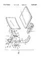
- FIG. 1shows a mechanism attached to a chair, in three-quarter exploded view
- FIG. 2shows the pin, frontal view
- FIG. 3shows the pin shown in FIG. 2, side view
- FIG. 4shows the flexible part, frontal view
- FIG. 5shows the rack, frontal view
- FIG. 6shows the curved cleat, partially reduced frontal view
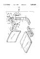
- FIG. 7shows the box unit, rear view
- FIG. 8shows the box unit of the previous figure; partial section lateral view
- FIG. 9partially shows the support bracket, frontal view
- FIGS. 10, 11, 12, 13, and 14partially show, in a front view, the mechanism with the pin while engaged and disengaged from the rack, and in these figures the curved cleat is omitted for greater clarity;
- FIG. 15shows, in three-quarter exploded view, the mechanism with the rack placed in a symmetrical position with respect to FIG. 1.
- the adjustment mechanismis indicated by number 1 and includes a box unit 2, attached at the rear to a seat back 3, into which support bracket 4 can be inserted and attached by sliding it in, and it extends behind and above a seat 5, being attached to the bottom of it with a common type of coupling device 6.
- the box unit 2includes bracket 7 with a first set of four holes numbered 9a, 9b, 9c, and 9d, and a cleat 8 which is curved and attached to this bracket.
- Bracket 7has two lateral ridges, 10a and 10b, parallel to each other and protruding from the bracket. During engagement with curved cleat 8, they create a primary sliding base 11, shaped to mate with the support bracket 4.
- the curved cleat 8has two wings, 12a and 12b, which protrude laterally on opposite sides and contain, respectively, a second pair of holes, 13a and 13b, and a third pair 13cand 13d ; these allow the curved cleat 8 to be attached to the seat back 3.
- Cleat 8also has a fourth set of four holes, indicated as 14a, 14b, 14c, and 14d and aligned along the same axes as the first set of holes, so that it may be attached to bracket 7 with screws.
- a second, essentially T-shaped slot 15is made in support bracket 4 by blanking, defined by a first, longitudinal slot 16a and, laterally, by a second slot 16b, which is substantially longer than the first. At both ends of the second slot 16b, there are two notches, 17a and 17b, which form a slot for attaching rack 18.
- Rack 18has, close to the first notch 17a, release structure in the form of a projection 19 for selective engagement of a pin 21, centrally attached to the primary sliding base 11. Close to the second notch 17b is actuator structure in the form of a projection 20 for the temporary disengagement of pin 21 itself.
- Rack 18also contains, between projection 19 and projection 20, numerous teeth 22, which are trapezoidal or triangular shape in section and oriented in the desired direction, such that the triangular shape of teeth 22 define disengagement structure for selectively disengaging pin 21 from teeth 22, in a manner to be explained.
- Projection 19consists of a tab 23, triangular in shape and protruding from rack 18, with point 23a connected with slot 15.
- the tab 23provides, together with the lower end of rack 18, a third support slot 24 for the end of pin 21.
- Projection 20, for temporary disengagementis formed by a second tab 25, which projects over the section of rack 18 containing teeth 22; pin 21 strikes against this and thereby disengages, as will be described further on.
- Pin 21which is essentially T-shaped, consists of a main central part 26; a second, cylindrical piece 27, solid or hollow, is transversely connected to its upper end; a third piece 28 is attached to its side at an The two extremities of the second, cylindrical piece 27 are inserted in a fifth hole 29a, bored through the center of bracket 7, and in a sixth hole 29b, bored on the same axis as the fifth hole 29a on the curved cleat 8. In this way, the second, cylindrical piece 27 is hinged, allowing pin 21 to swing freely on the sliding base 11.
- pin 21has a hollow cylindrical piece 27, the latter may connected to bracket 7 and cleat 8 by inserting a hinge pin through the fifth hole 29a and the sixth hole 29b.
- the third side piece 28 on pin 21is oriented along a direction at an acute angle from the vertical, measured positively in a counter-clockwise direction.
- the main central part 26 of pin 21has a third tooth 26a, lying below the pair of teeth 30a and 30b, having a lower surface 26b, angled parallel to the direction of side piece 28.
- bias meansin the form of a flexible part 31, comprised of a thin, essentially L-shaped plate to the side of pin 21, on the opposite side from piece 28, and interacting with rack 18.
- Flexible part 31consists of a longer arm 31a lined up parallel to the main central part 26 and a shorter arm 31b lined up perpendicular to the main part 26 and bent towards the third tooth 26a.
- flexible part 31At the end of large arm 31a and facing the main part 26, flexible part 31 has a curved part 31c which can be inserted between two pegs, 32a and 32b, that project perpendicularly from sliding base 11 on bracket 7.
- Flexible part 31has, at the end of short arm 31b, a projection 33 which can be engaged or engages with the lower surface 26b of the third tooth 26a such that projection 33 and lower surface 26b together define mating engagement or retaining structure for temporarily maintaining pin 21 in its disengaged position.
- Bracket 7contains a pair of third slots 35a and 35b, transversely cut into lateral ridge 10b and situated between holes 9c and 9d and the outer side edges of bracket 7.
- a pair of small tubes 36a and 36bcan be inserted into slots 35a and 35b. They can be made from rubber or a similarly elastic material, arranged longitudinally along the bracket, and having a slightly larger diameter than the width of the slots themselves.
- This pair of small tubes 36a and 36bcreates friction when bracket 7 slides along fixed cleat 8.
- the mechanismfunctions as follows: when the seat back is completely lowered side part 28 on pin 21 is at least partially inserted in support slot 24, and projection 33 remains set close to the lower surface 26b of the third tooth 26.
- Pin 21is thereby set in a temporarily disengaged position with respect to rack 18.
- the presence of the flexible partin addition to providing for optimal interaction between the pin and the rack teeth, blocks the pin by altering the catch point with the rack by keeping it disengaged from the rack itself; this prevents the pin from accidentally engaging with the first teeth on the rack and thus saves the user from having to carry out a series of tiring back-and-forth movements with the seat back in order to reach the desired position.
- this mechanismoffers low fabrication costs.
- the second slot 16bcan be symmetrically oriented with respect to the figures described hitherto, thus realizing a symmetrical arrangement for all the components in the mechanism.
- the materials and measurements usedcan be whatever particular needs require.
Landscapes
- Chairs For Special Purposes, Such As Reclining Chairs (AREA)
- Chair Legs, Seat Parts, And Backrests (AREA)
Abstract
Description
Claims (17)
Applications Claiming Priority (2)
| Application Number | Priority Date | Filing Date | Title |
|---|---|---|---|
| ITTV950016U | 1995-03-21 | ||
| IT1995TV000016UIT239565Y1 (en) | 1995-03-21 | 1995-03-21 | HEIGHT ADJUSTMENT DEVICE FOR A CHAIR BACKREST |
Publications (1)
| Publication Number | Publication Date |
|---|---|
| US5685609Atrue US5685609A (en) | 1997-11-11 |
Family
ID=11419588
Family Applications (1)
| Application Number | Title | Priority Date | Filing Date |
|---|---|---|---|
| US08/449,479Expired - LifetimeUS5685609A (en) | 1995-03-21 | 1995-05-30 | Mechanism to adjust the height of a back support of a chair |
Country Status (4)
| Country | Link |
|---|---|
| US (1) | US5685609A (en) |
| CA (1) | CA2171651C (en) |
| IT (1) | IT239565Y1 (en) |
| MX (1) | MX9601044A (en) |
Cited By (38)
| Publication number | Priority date | Publication date | Assignee | Title |
|---|---|---|---|---|
| US5918938A (en)* | 1996-11-05 | 1999-07-06 | Nowy Styl Sp. Z O.O. | Safety device for mechanisms for lifting the back of a chair or armchair |
| US5951107A (en)* | 1998-10-28 | 1999-09-14 | Tornero; Lino E. | Height adjusting device with audible feedback |
| US6000756A (en)* | 1997-03-12 | 1999-12-14 | Leggett & Platt, Inc. | Synchronized chair seat and backrest tilt control mechanism |
| US6155643A (en)* | 1996-09-06 | 2000-12-05 | Imarc S.P.A. | Device for adjusting the height of the back-rest of a seat back portion, in particular in office chairs |
| US6238000B1 (en) | 1998-02-04 | 2001-05-29 | Unit Press Limited | Mechanism for chair |
| US6264276B1 (en)* | 2000-07-21 | 2001-07-24 | Su-Ming Chen | Adjustable connecting device for interconnecting seat and backrest members of a chair |
| US6273384B1 (en)* | 1998-05-22 | 2001-08-14 | Unit Press Limited | Chair back adjustment mechanism |
| US6276757B1 (en)* | 1998-11-23 | 2001-08-21 | Klasse Pty Ltd. | Back support improvement |
| US6299253B1 (en)* | 1999-08-19 | 2001-10-09 | Chao Ken Chen | Telescopic positioning mechanism for chair backrest |
| US6422652B1 (en) | 2000-11-29 | 2002-07-23 | Haworth, Inc. | Height adjusting mechanism |
| US6517041B2 (en)* | 2000-08-12 | 2003-02-11 | Grammer Ag | Displacement arrangement |
| US6533355B2 (en) | 2001-03-28 | 2003-03-18 | Haworth, Inc. | Height-adjustment mechanism for a chair |
| US6540296B1 (en) | 2001-03-01 | 2003-04-01 | Ram Machines (1990) Ltd. | Chair back height-adjustment mechanism |
| US20030071506A1 (en)* | 2001-09-25 | 2003-04-17 | Burgin Ralph C. | Chair adjustment mechanism |
| US6598936B1 (en) | 2001-04-11 | 2003-07-29 | Michael N. Klein | Multi-task mid-pivot chair control mechanism |
| US6598937B2 (en)* | 1998-01-21 | 2003-07-29 | Herman Miller, Inc. | Adjustable backrest |
| AU765002B2 (en)* | 1998-11-23 | 2003-09-04 | Klasse Pty Ltd | Back support improvement |
| US6619745B2 (en) | 1999-12-03 | 2003-09-16 | Unit Press Limited | Connection assembly for a chair back |
| US6751921B1 (en)* | 1998-08-27 | 2004-06-22 | Nippon Eisei Center Co., Ltd. | Earthquake-proofing reinforcing metal fitting |
| US20040124678A1 (en)* | 2002-02-11 | 2004-07-01 | Graco Children's Products Inc. | Child seat |
| GB2401037A (en)* | 2003-05-02 | 2004-11-03 | Yu-Shan Lai | Lifting adjustment mechanism |
| US20040221679A1 (en)* | 2003-04-26 | 2004-11-11 | Holger Raum | Ratchet-type adjustment device |
| US20060131944A1 (en)* | 2004-12-17 | 2006-06-22 | Gerard Helmond | Chair adjustment mechanism |
| US20060232115A1 (en)* | 2005-03-18 | 2006-10-19 | Ching-Hui Chi | Backrest elevation adjustment assembly |
| US7243997B1 (en) | 2004-01-20 | 2007-07-17 | Tornero Lino E | Positioning device for furniture |
| US20070200407A1 (en)* | 2006-02-27 | 2007-08-30 | Eberlein David C | Seating unit with adjustable components |
| US20070246988A1 (en)* | 2006-04-25 | 2007-10-25 | Ching-Lin Hung | Adjustment structure of chair backrests |
| US20100038949A1 (en)* | 2008-08-14 | 2010-02-18 | Liao Tzu-Ying | Adjustable chair headrest frame |
| DE102009014777A1 (en) | 2009-03-25 | 2010-09-30 | Wilkhahn Wilkening + Hahne Gmbh + Co. Kg | adjustment |
| US20110215623A1 (en)* | 2010-03-04 | 2011-09-08 | Hsuan-Chin Tsai | Height-Adjusting Assembly for Office Chair Backrest |
| US20120019038A1 (en)* | 2010-07-23 | 2012-01-26 | Marcelo Mezzera | Back connecting bar for the no-tools connection of a chair back to a chair seat |
| EP2873347A1 (en)* | 2013-11-18 | 2015-05-20 | Ferdinand Lusch Gmbh & Co. Kg. | Piece of furniture having an adjustable functional component |
| US9096151B2 (en) | 2011-05-27 | 2015-08-04 | Husqvarna Ab | Lawn care vehicle adjustable seat |
| US9668582B2 (en) | 2015-01-15 | 2017-06-06 | Ram Machines (1990) Ltd. | Linear adjustment mechanism |
| US11191361B2 (en)* | 2019-02-22 | 2021-12-07 | Includehealth, Inc. | Seat adjustment mechanism |
| US11589678B2 (en) | 2019-01-17 | 2023-02-28 | Hni Technologies Inc. | Chairs including flexible frames |
| WO2023207088A1 (en)* | 2022-04-25 | 2023-11-02 | 安吉瑞宝家具有限公司 | Chair back lifting/lowering mechanism |
| WO2024128923A1 (en)* | 2022-12-14 | 2024-06-20 | Sapdesign As | An adjustment device for a chair backrest |
Citations (23)
| Publication number | Priority date | Publication date | Assignee | Title |
|---|---|---|---|---|
| US848001A (en)* | 1905-02-20 | 1907-03-26 | Eugene Berninghaus | Head-rest for barber and other chairs. |
| US3309050A (en)* | 1965-05-06 | 1967-03-14 | Mitchell Mfg Company | Adjustable table legs |
| US3460794A (en)* | 1967-06-14 | 1969-08-12 | Gen Motors Corp | Seat adjuster |
| US3526430A (en)* | 1968-11-18 | 1970-09-01 | Art Metal Knoll Corp | Back height adjustment mechanism |
| US3854772A (en)* | 1973-05-25 | 1974-12-17 | All Steel Inc | Backrest height adjustment device for office furniture chairs |
| US3917341A (en)* | 1974-05-28 | 1975-11-04 | Westinghouse Electric Corp | Chair back height adjustment mechanism |
| US4012158A (en)* | 1975-09-15 | 1977-03-15 | Harper Henry J | Adjustable seat-back mechanism |
| US4015878A (en)* | 1976-01-16 | 1977-04-05 | Perkins Charles M | Chair construction for long use comfort |
| US4036525A (en)* | 1976-04-08 | 1977-07-19 | Gf Business Equipment, Inc. | Backrest adjustment mechanism |
| US4043592A (en)* | 1975-09-05 | 1977-08-23 | Steelcase Inc. | Adjustable seat back mechanism |
| US4221430A (en)* | 1978-05-18 | 1980-09-09 | Jasper Corporation | Push button adjuster for chair backrest |
| US4384742A (en)* | 1981-03-11 | 1983-05-24 | Haworth, Inc. | Height adjusting mechanism for chair back |
| EP0081898A2 (en)* | 1981-12-14 | 1983-06-22 | Simmons Universal Corporation | An adjustment means |
| US4466665A (en)* | 1982-01-25 | 1984-08-21 | Robert Aronowitz | Chair having adjsutable, cantilevered lumbar-supporting arm |
| US4616877A (en)* | 1985-05-09 | 1986-10-14 | Kimball International, Inc. | Chair with back height adjustment |
| US4639039A (en)* | 1985-09-10 | 1987-01-27 | Milsco Manufacturing Company | Height adjustment mechanism for chair backrest |
| US4660885A (en)* | 1985-08-02 | 1987-04-28 | Firma August Froscher Gmbh & Co. K.G. | Adjusting mechanism for the step-wise locking height adjustment of backrest of work chair |
| US4749230A (en)* | 1987-04-23 | 1988-06-07 | Tornero Lino E | Height adjusting device for chair backrest |
| US4786108A (en)* | 1986-10-16 | 1988-11-22 | Burositzmobelfabrik Friedrich-W. Dauphin Gmbh & Co. | Chair, in particular office chair, with a vertically adjustable back rest support |
| US4930840A (en)* | 1989-07-03 | 1990-06-05 | Tornero Lino E | Hinged height adjusting device |
| US5037158A (en)* | 1990-01-16 | 1991-08-06 | Westinghouse Electric Corporation | Height adjustment mechanism for chair back |
| US5286088A (en)* | 1990-06-12 | 1994-02-15 | Unit Press Limited | Underseat mechanism for a chair |
| US5405189A (en)* | 1993-08-09 | 1995-04-11 | Doerner Products Ltd. | Chair seat back height adjustment mechanism |
- 1995
- 1995-03-21ITIT1995TV000016Upatent/IT239565Y1/enactive
- 1995-05-30USUS08/449,479patent/US5685609A/ennot_activeExpired - Lifetime
- 1996
- 1996-03-13CACA002171651Apatent/CA2171651C/ennot_activeExpired - Fee Related
- 1996-03-20MXMX9601044Apatent/MX9601044A/enunknown
Patent Citations (24)
| Publication number | Priority date | Publication date | Assignee | Title |
|---|---|---|---|---|
| US848001A (en)* | 1905-02-20 | 1907-03-26 | Eugene Berninghaus | Head-rest for barber and other chairs. |
| US3309050A (en)* | 1965-05-06 | 1967-03-14 | Mitchell Mfg Company | Adjustable table legs |
| US3460794A (en)* | 1967-06-14 | 1969-08-12 | Gen Motors Corp | Seat adjuster |
| US3526430A (en)* | 1968-11-18 | 1970-09-01 | Art Metal Knoll Corp | Back height adjustment mechanism |
| US3854772A (en)* | 1973-05-25 | 1974-12-17 | All Steel Inc | Backrest height adjustment device for office furniture chairs |
| US3917341A (en)* | 1974-05-28 | 1975-11-04 | Westinghouse Electric Corp | Chair back height adjustment mechanism |
| US4043592A (en)* | 1975-09-05 | 1977-08-23 | Steelcase Inc. | Adjustable seat back mechanism |
| US4012158A (en)* | 1975-09-15 | 1977-03-15 | Harper Henry J | Adjustable seat-back mechanism |
| US4015878A (en)* | 1976-01-16 | 1977-04-05 | Perkins Charles M | Chair construction for long use comfort |
| US4036525A (en)* | 1976-04-08 | 1977-07-19 | Gf Business Equipment, Inc. | Backrest adjustment mechanism |
| US4221430A (en)* | 1978-05-18 | 1980-09-09 | Jasper Corporation | Push button adjuster for chair backrest |
| US4384742A (en)* | 1981-03-11 | 1983-05-24 | Haworth, Inc. | Height adjusting mechanism for chair back |
| EP0081898A2 (en)* | 1981-12-14 | 1983-06-22 | Simmons Universal Corporation | An adjustment means |
| US4451084A (en)* | 1981-12-14 | 1984-05-29 | Simmons Universal Corporation | Backrest height adjustment for office chair |
| US4466665A (en)* | 1982-01-25 | 1984-08-21 | Robert Aronowitz | Chair having adjsutable, cantilevered lumbar-supporting arm |
| US4616877A (en)* | 1985-05-09 | 1986-10-14 | Kimball International, Inc. | Chair with back height adjustment |
| US4660885A (en)* | 1985-08-02 | 1987-04-28 | Firma August Froscher Gmbh & Co. K.G. | Adjusting mechanism for the step-wise locking height adjustment of backrest of work chair |
| US4639039A (en)* | 1985-09-10 | 1987-01-27 | Milsco Manufacturing Company | Height adjustment mechanism for chair backrest |
| US4786108A (en)* | 1986-10-16 | 1988-11-22 | Burositzmobelfabrik Friedrich-W. Dauphin Gmbh & Co. | Chair, in particular office chair, with a vertically adjustable back rest support |
| US4749230A (en)* | 1987-04-23 | 1988-06-07 | Tornero Lino E | Height adjusting device for chair backrest |
| US4930840A (en)* | 1989-07-03 | 1990-06-05 | Tornero Lino E | Hinged height adjusting device |
| US5037158A (en)* | 1990-01-16 | 1991-08-06 | Westinghouse Electric Corporation | Height adjustment mechanism for chair back |
| US5286088A (en)* | 1990-06-12 | 1994-02-15 | Unit Press Limited | Underseat mechanism for a chair |
| US5405189A (en)* | 1993-08-09 | 1995-04-11 | Doerner Products Ltd. | Chair seat back height adjustment mechanism |
Cited By (53)
| Publication number | Priority date | Publication date | Assignee | Title |
|---|---|---|---|---|
| US6155643A (en)* | 1996-09-06 | 2000-12-05 | Imarc S.P.A. | Device for adjusting the height of the back-rest of a seat back portion, in particular in office chairs |
| US5918938A (en)* | 1996-11-05 | 1999-07-06 | Nowy Styl Sp. Z O.O. | Safety device for mechanisms for lifting the back of a chair or armchair |
| US6000756A (en)* | 1997-03-12 | 1999-12-14 | Leggett & Platt, Inc. | Synchronized chair seat and backrest tilt control mechanism |
| US6010189A (en)* | 1997-03-12 | 2000-01-04 | Leggett & Platt, Incorporated | Synchronized chair seat and backrest tilt control mechanism |
| US6139103A (en)* | 1997-03-12 | 2000-10-31 | Leggett & Platt, Inc. | Synchronized chair seat and backrest tilt control mechanism |
| US6598937B2 (en)* | 1998-01-21 | 2003-07-29 | Herman Miller, Inc. | Adjustable backrest |
| US6238000B1 (en) | 1998-02-04 | 2001-05-29 | Unit Press Limited | Mechanism for chair |
| US6273384B1 (en)* | 1998-05-22 | 2001-08-14 | Unit Press Limited | Chair back adjustment mechanism |
| US6751921B1 (en)* | 1998-08-27 | 2004-06-22 | Nippon Eisei Center Co., Ltd. | Earthquake-proofing reinforcing metal fitting |
| US5951107A (en)* | 1998-10-28 | 1999-09-14 | Tornero; Lino E. | Height adjusting device with audible feedback |
| AU765002B2 (en)* | 1998-11-23 | 2003-09-04 | Klasse Pty Ltd | Back support improvement |
| US6276757B1 (en)* | 1998-11-23 | 2001-08-21 | Klasse Pty Ltd. | Back support improvement |
| US6299253B1 (en)* | 1999-08-19 | 2001-10-09 | Chao Ken Chen | Telescopic positioning mechanism for chair backrest |
| US6619745B2 (en) | 1999-12-03 | 2003-09-16 | Unit Press Limited | Connection assembly for a chair back |
| US6264276B1 (en)* | 2000-07-21 | 2001-07-24 | Su-Ming Chen | Adjustable connecting device for interconnecting seat and backrest members of a chair |
| US6517041B2 (en)* | 2000-08-12 | 2003-02-11 | Grammer Ag | Displacement arrangement |
| US6422652B1 (en) | 2000-11-29 | 2002-07-23 | Haworth, Inc. | Height adjusting mechanism |
| US6540296B1 (en) | 2001-03-01 | 2003-04-01 | Ram Machines (1990) Ltd. | Chair back height-adjustment mechanism |
| US6533355B2 (en) | 2001-03-28 | 2003-03-18 | Haworth, Inc. | Height-adjustment mechanism for a chair |
| US6598936B1 (en) | 2001-04-11 | 2003-07-29 | Michael N. Klein | Multi-task mid-pivot chair control mechanism |
| US6779847B2 (en) | 2001-04-11 | 2004-08-24 | L & P Property Management Company | Multi-task mid-pivot chair control mechanism |
| US6793286B2 (en)* | 2001-09-25 | 2004-09-21 | Hon Technology Inc. | Chair adjustment mechanism |
| US20030071506A1 (en)* | 2001-09-25 | 2003-04-17 | Burgin Ralph C. | Chair adjustment mechanism |
| US20050082888A1 (en)* | 2002-02-11 | 2005-04-21 | Graco Children's Products Inc. | Child seat |
| US20040124678A1 (en)* | 2002-02-11 | 2004-07-01 | Graco Children's Products Inc. | Child seat |
| US7370912B2 (en) | 2002-02-11 | 2008-05-13 | Graco Children's Products, Inc. | Child seat |
| US20040221679A1 (en)* | 2003-04-26 | 2004-11-11 | Holger Raum | Ratchet-type adjustment device |
| US7357051B2 (en)* | 2003-04-26 | 2008-04-15 | Grammer Ag | Ratchet-type adjustment device |
| GB2401037B (en)* | 2003-05-02 | 2005-03-30 | Yu-Shan Lai | Lifting adjustment device |
| GB2401037A (en)* | 2003-05-02 | 2004-11-03 | Yu-Shan Lai | Lifting adjustment mechanism |
| US7243997B1 (en) | 2004-01-20 | 2007-07-17 | Tornero Lino E | Positioning device for furniture |
| US20060131944A1 (en)* | 2004-12-17 | 2006-06-22 | Gerard Helmond | Chair adjustment mechanism |
| US7188901B2 (en)* | 2004-12-17 | 2007-03-13 | Leggett & Platt Ltd. | Chair adjustment mechanism |
| US20060232115A1 (en)* | 2005-03-18 | 2006-10-19 | Ching-Hui Chi | Backrest elevation adjustment assembly |
| US7275790B2 (en)* | 2005-03-18 | 2007-10-02 | Ching-Hui Chi | Backrest elevation adjustment assembly |
| US20070200407A1 (en)* | 2006-02-27 | 2007-08-30 | Eberlein David C | Seating unit with adjustable components |
| US20070246988A1 (en)* | 2006-04-25 | 2007-10-25 | Ching-Lin Hung | Adjustment structure of chair backrests |
| US20100038949A1 (en)* | 2008-08-14 | 2010-02-18 | Liao Tzu-Ying | Adjustable chair headrest frame |
| US7690729B2 (en)* | 2008-08-14 | 2010-04-06 | Liao Tzu-Ying | Adjustable chair headrest frame |
| DE102009014777A1 (en) | 2009-03-25 | 2010-09-30 | Wilkhahn Wilkening + Hahne Gmbh + Co. Kg | adjustment |
| DE102009014777B4 (en) | 2009-03-25 | 2017-03-30 | Wilkhahn Wilkening + Hahne Gmbh + Co. Kg | adjustment |
| US20110175415A1 (en)* | 2009-03-25 | 2011-07-21 | Ralph Baumann | Adjustment device |
| US8651577B2 (en) | 2009-03-25 | 2014-02-18 | Wilkhan Wilkening & Hahne GmbH & Co. KG | Adjustment device |
| US20110215623A1 (en)* | 2010-03-04 | 2011-09-08 | Hsuan-Chin Tsai | Height-Adjusting Assembly for Office Chair Backrest |
| US20120019038A1 (en)* | 2010-07-23 | 2012-01-26 | Marcelo Mezzera | Back connecting bar for the no-tools connection of a chair back to a chair seat |
| US9096151B2 (en) | 2011-05-27 | 2015-08-04 | Husqvarna Ab | Lawn care vehicle adjustable seat |
| EP2873347A1 (en)* | 2013-11-18 | 2015-05-20 | Ferdinand Lusch Gmbh & Co. Kg. | Piece of furniture having an adjustable functional component |
| US9668582B2 (en) | 2015-01-15 | 2017-06-06 | Ram Machines (1990) Ltd. | Linear adjustment mechanism |
| US11589678B2 (en) | 2019-01-17 | 2023-02-28 | Hni Technologies Inc. | Chairs including flexible frames |
| US12075921B2 (en) | 2019-01-17 | 2024-09-03 | Hni Technologies Inc. | Chairs including flexible frames |
| US11191361B2 (en)* | 2019-02-22 | 2021-12-07 | Includehealth, Inc. | Seat adjustment mechanism |
| WO2023207088A1 (en)* | 2022-04-25 | 2023-11-02 | 安吉瑞宝家具有限公司 | Chair back lifting/lowering mechanism |
| WO2024128923A1 (en)* | 2022-12-14 | 2024-06-20 | Sapdesign As | An adjustment device for a chair backrest |
Also Published As
| Publication number | Publication date |
|---|---|
| ITTV950016V0 (en) | 1995-03-21 |
| CA2171651A1 (en) | 1996-09-22 |
| ITTV950016U1 (en) | 1996-09-21 |
| IT239565Y1 (en) | 2001-03-05 |
| CA2171651C (en) | 2000-02-29 |
| MX9601044A (en) | 1997-02-28 |
Similar Documents
| Publication | Publication Date | Title |
|---|---|---|
| US5685609A (en) | Mechanism to adjust the height of a back support of a chair | |
| CA1180655A (en) | Backrest height adjustment for office chair | |
| EP1559347B1 (en) | Height adjustment mechanism for a chair | |
| US6076892A (en) | Multi-adjustable armrest assembly | |
| US5649741A (en) | Adjusting mechanism | |
| US4430771A (en) | Hinge bracket-mounting plate assembly | |
| US5324096A (en) | Adjustable height chair arm | |
| CA2341342C (en) | Arm height adjustment mechanism for a chair | |
| US6299253B1 (en) | Telescopic positioning mechanism for chair backrest | |
| US6398304B1 (en) | Highchair with an improved seat angle adjustment mechanism | |
| CN1937936A (en) | Chair with tilt lock mechanism | |
| US6173980B1 (en) | Child's bicycle seat and rack assembly | |
| EP1807282B1 (en) | Seat slide adjustment mechanism | |
| CA3043094A1 (en) | Pivot joint with defined pressure point | |
| US7341233B2 (en) | Horizontal adjustment mechanism for use on a chair seat | |
| US6540296B1 (en) | Chair back height-adjustment mechanism | |
| US4589674A (en) | Apparatus for facilitating a longitudinal adjustment of ski-binding parts | |
| CA2516965C (en) | Chair adjustment mechanism | |
| US5351978A (en) | Double-lock height adjustment apparatus for baby walker | |
| US7510207B2 (en) | Ski binding with a positioning and fixing mechanism for the jaw bodies | |
| US6273384B1 (en) | Chair back adjustment mechanism | |
| US6851752B2 (en) | Height adjustment mechanism for an infant support structure | |
| EP1695643A2 (en) | Elbow rest and chair | |
| KR200371588Y1 (en) | Stopper for regulating angle of the chair back | |
| US4000908A (en) | Ski binding component |
Legal Events
| Date | Code | Title | Description |
|---|---|---|---|
| AS | Assignment | Owner name:MIOTTO INTERNATIONAL COMPANY, WISCONSIN Free format text:ASSIGNMENT OF ASSIGNORS INTEREST;ASSIGNOR:MIOTTO, BENIAMINO;REEL/FRAME:007641/0862 Effective date:19950920 | |
| STCF | Information on status: patent grant | Free format text:PATENTED CASE | |
| FEPP | Fee payment procedure | Free format text:PAYOR NUMBER ASSIGNED (ORIGINAL EVENT CODE: ASPN); ENTITY STATUS OF PATENT OWNER: LARGE ENTITY | |
| FPAY | Fee payment | Year of fee payment:4 | |
| AS | Assignment | Owner name:L & P PROPERTY MANAGMENT COMPANY, CALIFORNIA Free format text:ASSIGNMENT OF ASSIGNORS INTEREST;ASSIGNOR:OLYMPIC INDUSTRIES, INCORPORATION, FORMERLY MIOTTO INTERNATIONAL COMPANY;REEL/FRAME:015000/0392 Effective date:20040116 | |
| FPAY | Fee payment | Year of fee payment:8 | |
| FEPP | Fee payment procedure | Free format text:PAYOR NUMBER ASSIGNED (ORIGINAL EVENT CODE: ASPN); ENTITY STATUS OF PATENT OWNER: LARGE ENTITY Free format text:PAYER NUMBER DE-ASSIGNED (ORIGINAL EVENT CODE: RMPN); ENTITY STATUS OF PATENT OWNER: LARGE ENTITY | |
| FPAY | Fee payment | Year of fee payment:12 |