US5685097A - Illuminated colored display device - Google Patents
Illuminated colored display deviceDownload PDFInfo
- Publication number
- US5685097A US5685097AUS08/575,255US57525595AUS5685097AUS 5685097 AUS5685097 AUS 5685097AUS 57525595 AUS57525595 AUS 57525595AUS 5685097 AUS5685097 AUS 5685097A
- Authority
- US
- United States
- Prior art keywords
- translucent member
- base
- translucent
- supported
- decorative device
- Prior art date
- Legal status (The legal status is an assumption and is not a legal conclusion. Google has not performed a legal analysis and makes no representation as to the accuracy of the status listed.)
- Expired - Lifetime
Links
- 239000003086colorantSubstances0.000claimsabstractdescription27
- 238000005286illuminationMethods0.000claimsdescription13
- 230000000007visual effectEffects0.000description6
- 239000007788liquidSubstances0.000description4
- XLYOFNOQVPJJNP-UHFFFAOYSA-NwaterSubstancesOXLYOFNOQVPJJNP-UHFFFAOYSA-N0.000description2
- 239000013078crystalSubstances0.000description1
- 238000006073displacement reactionMethods0.000description1
- 230000001788irregularEffects0.000description1
- 239000000463materialSubstances0.000description1
- 238000012986modificationMethods0.000description1
- 230000004048modificationEffects0.000description1
- 238000010422paintingMethods0.000description1
- GVKCHTBDSMQENH-UHFFFAOYSA-Lphloxine BChemical compound[Na+].[Na+].[O-]C(=O)C1=C(Cl)C(Cl)=C(Cl)C(Cl)=C1C1=C2C=C(Br)C(=O)C(Br)=C2OC2=C(Br)C([O-])=C(Br)C=C21GVKCHTBDSMQENH-UHFFFAOYSA-L0.000description1
Images


Classifications
- G—PHYSICS
- G09—EDUCATION; CRYPTOGRAPHY; DISPLAY; ADVERTISING; SEALS
- G09F—DISPLAYING; ADVERTISING; SIGNS; LABELS OR NAME-PLATES; SEALS
- G09F19/00—Advertising or display means not otherwise provided for
- G09F19/02—Advertising or display means not otherwise provided for incorporating moving display members
- G09F19/08—Dolls, faces, or other representations of living forms with moving parts
- G—PHYSICS
- G09—EDUCATION; CRYPTOGRAPHY; DISPLAY; ADVERTISING; SEALS
- G09F—DISPLAYING; ADVERTISING; SIGNS; LABELS OR NAME-PLATES; SEALS
- G09F19/00—Advertising or display means not otherwise provided for
- G09F19/02—Advertising or display means not otherwise provided for incorporating moving display members
- Y—GENERAL TAGGING OF NEW TECHNOLOGICAL DEVELOPMENTS; GENERAL TAGGING OF CROSS-SECTIONAL TECHNOLOGIES SPANNING OVER SEVERAL SECTIONS OF THE IPC; TECHNICAL SUBJECTS COVERED BY FORMER USPC CROSS-REFERENCE ART COLLECTIONS [XRACs] AND DIGESTS
- Y10—TECHNICAL SUBJECTS COVERED BY FORMER USPC
- Y10S—TECHNICAL SUBJECTS COVERED BY FORMER USPC CROSS-REFERENCE ART COLLECTIONS [XRACs] AND DIGESTS
- Y10S362/00—Illumination
- Y10S362/806—Ornamental or decorative
- Y10S362/811—Psychedelic lighting
Definitions
- This inventionrelates to illuminated colored display devices, and more particularly to a display device which presents the visual effect of changing colors in changing patterns of shapes when viewed by an observer.
- the Ream patentdiscloses an ornamental display device wherein a bulb is located in a rotating drum which is provided with perforations through which light projects to a clear plastic cylindrical shell.
- the Mole patentdescribes an illuminating device wherein three lens of different colors are mounted in a triangular form on a support which rotates about a light source. The light passing through the lens also passed through an aperture formed in the spherical housing containing the light source and lens.
- the Naylor patentillustrates a lighting apparatus wherein two concentric cylindrical light transmissive members having designs thereon are caused to counter-rotated around a light source.
- the heat generated by the light sourcecauses air currents to engage blades secured to the cylinders to cause them to rotate.
- the Mollica patentsets forth a device for providing visual effects including a source of black light located within a rotatable hollow cylindrical translucent element having a pattern thereon subject to fluorescence.
- the translucent elementis surrounded by a cylindrical lens which is located within a translucent rectangular housing.
- the Teng patentreveals a display device which includes a crystal ball having a plurality of concave and convex portions which when filled with water form concave and convex lens through which is observed a decorative article within the ball.
- the ballis caused to rotate with respect to the base on which it is supported.
- the Brown patentis directed to a submersible device for changing colors in an aquarium, wherein a domed member having transparent plates of varying colors is caused to rotate around a light source, with the light of varying colors projecting into the water through clear transparent windows in a housing enclosing the device.
- an illuminated colored display devicewhich includes a base, and at least two translucent members which are supported on turntables which are in turn supported by the base and are rotated with respect to the base by a drive system included in the base.
- the translucent memberswhich in the preferred embodiment are of a frustum shape, surround a source of illumination which is also supported on the base. Colored patterns consisting or areas of two or more colors or clear areas are provided on the translucent members.
- a third translucent member, which is supported on the base in a fixed positionis of the same general shape as the others, but is formed with regions of varying thickness such that it distorts the light passing through it so as to both magnify and reduce the various colored areas to provide a visual effect which varies in color, and shape.
- An opaque coveris supported on the third translucent member over the ends of all of the translucent members. The translucent members may be lifted from the base to gain access to the source of illumination which in the preferred embodiment is an electric light bulb.
- FIG. 1is a perspective view of an illuminated decorative device in accordance with this invention.
- FIG. 2is an exploded perspective view of the illuminated decorative device in accordance with this invention.
- FIG. 3is a top plan view with portions removed and other portions broken away of the base of the illuminated decorative device in accordance with this invention.
- FIG. 4is a cross-sectional view of the base of the illuminated decorative device in accordance with this invention taken along the lines 4--4 in FIG. 1.
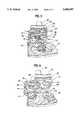
- FIG. 5is an exploded fragmentary view of a portion of the illuminated decorative device in accordance with this invention.
- FIG. 6is an exploded fragmentary view similar to FIG. 5 showing portions of the illuminated decorative device in accordance with this invention in a different position.
- FIGS. 1 and 2a preferred embodiment of the illuminated decorative device 10 of this invention is shown.
- the principal components of the illuminated decorative deviceare a base 12, a first translucent member 14, a second translucent member 16, a third translucent member 18 and a cap 20.
- the first, second and third translucent members 14, 16 and 18are of a generally cylindrical or more particularly a frustum shape, with the larger diameter end being positioned toward the base and the smaller diameter end being positioned away from the base.
- the second translucent member 16is of a larger diameter than the first translucent member 14, and the third translucent member 18 is of a larger diameter than the second translucent member 16, such that the third translucent member may be placed around the second and the second around the first.
- the first, second and third translucent membersare formed of a clear translucent plastic body.
- Translucent color patternsare provided on the surfaces of the first and second translucent members 14 and 16. As shown in FIGS. 2, 5, and 6, a two-color pattern consisting of red 28 and yellow 30 areas is provided on the surface of the first translucent member 14. This color pattern may be applied in various ways, such as by painting, for instance by silk screen or by securing a transparent film formed with areas of each of the colors, to the member 14, or by applying two films, each of which bears one of the colors. Similarly, a colored pattern is provided on the surface of the second translucent member 16. As illustrated in FIGS. 2, 5, and 6, blue 32 and yellow 34 areas are provided, as well as clear areas 36. Further, in some areas, the blue and yellow overlap so as to provide a generally green area 38. Again, the colored areas may be provided in numerous different ways known in the art.
- the third translucent member 18has a generally smooth inner surface and a wave-like outer surface, such that it has alternate thin areas 40 and thick areas 42. These alternating thin and thick areas provide a vertically oriented pattern of alternating magnifying and reducing portions.
- a drive systemis provided in the base 12, which in conjunction with turntables supporting the first and second translucent members 14 and 16, causes each of them to rotate with respect to the base in an opposite direction with respect to each other.
- the first and second translucent membersrotating in the illuminated decorative device as shown in FIG. 1, varying patterns of shape and color are observed at a fixed point spaced from the illuminated decorative device.
- the truncated cone-shaped base 10is provided with a top 44, from which is suspended by downwardly projecting posts 46, a portion of one of which is shown, an electric drive motor 48.
- the output shaft of the drive motorhas affixed thereto a gear 52 which engages a gear 54 which is connected to a shaft, (not shown) which extends through the top 44 and has secured thereto a pair of gears 56 and 58 which are of different diameters.
- the smaller diameter gear 58drives still another gear 60 which is supported on a post 62 extending from the base 44.
- the gear 56also drives a gear 64 which is supported from another post 66 which extends from the base 44.
- a first turntable 68 as shown in FIGS. 3 and 4is provided for supporting the first translucent member 14.
- the first turntable 68has an aperture therein such that it fits over an upwardly extending cylindrical member 70 of the top 44.
- a downwardly projecting cylindrical member 71is provided on the first turntable 68.
- a second turntable 74is provided for supporting the second translucent member 16.
- the second turntable 74is provided with a downwardly extending cylindrical portion 76, on the inner surface of which is formed a gear 78.
- the gear 78is engaged by the gear 64 such that the second turntable 74 is also driven by the electric motor 48.
- the drive train for the first turntable 68, which supports the first translucent member 14includes gears 52, 54, 56, 60 and 72.
- the drive train for the second turntable 74, which supports the second translucent member 16,includes gears, 52, 54, 58, 64 and 78. It will be apparent to a person skilled in the art that by varying the diameters of the various gears involved in the gear trains, the speeds of rotation of the turntables 68 and 74 may be changed with respect to the base 12, and also with respect to each other. Thus, with the drive trains as shown, energization of the motor 48 will cause the turntables 68 and 74 and therefore the first and second translucent members 14 and 16 to rotate in opposite directions with respect to each other.
- a electrical lamp socket 80for receiving and energizing a source of illumination 82 such as an incandescent light bulb as shown in FIGS. 5 and 6.
- the energized light bulbprovides light which is transmitted through first, second and third translucent members to a viewers eyes.
- the light source 82is shown along with exploded, partial sectional views, of the first translucent member 14, the second translucent member 16 and the third translucent member 18.
- the first translucent memberis shown to have a pattern of red and yellow areas.
- the second translucent memberis shown to have blue, yellow, green and clear areas.
- changing color patternsare observed through the third translucent member 18 due to the motion of the first and second translucent members 14 and 16 with respect to each other.
- the colors represented on the third translucent member 18, in FIGS. 5 and 6are those which are viewed from an external point.
- FIG. 6is similar to FIG. 5, but shows the first and second translucent members 14 and 16 in a subsequent position with respect to each other.
- a comparison of the colored areas on third translucent member 18 in FIGS. 5 and 6illustrates the changing of the pattern and of the color as observed through member 18 due to the displacement of members 14 and 16 with respect to each other.
- a translucent but light dispersing thin member 84may be provided between light source 82 and the first translucent member 14, to disperse the light emitted from the source 82, so as to eliminate the viewing of a particularly bright spot through the three translucent members.
- an opaque cap 20is placed upon the top of the third translucent member 18 and supported thereby.
- Annular openings 84, 86 and 88are provided in the top of the cap 20 to permit The convective air flow through the base and inside the first translucent member 14 around the lamp 82 to dissipate the heat generated thereby.
- first, second and third translucent members and the cap 20may be easily lifted off the base 12 and the turntables 68 and 74 to gain access to the bulb 82.
Landscapes
- Business, Economics & Management (AREA)
- Accounting & Taxation (AREA)
- Marketing (AREA)
- Physics & Mathematics (AREA)
- General Physics & Mathematics (AREA)
- Engineering & Computer Science (AREA)
- Theoretical Computer Science (AREA)
- Non-Portable Lighting Devices Or Systems Thereof (AREA)
- Illuminated Signs And Luminous Advertising (AREA)
Abstract
Description
______________________________________ 2,867,716 -- Ream 3,791,058 -- Mollica 3,179,791 -- Mole 5,065,289 -- Teng 3,686,494 -- Naylor 5,394,309 -- Brown ______________________________________
Claims (13)
Priority Applications (1)
| Application Number | Priority Date | Filing Date | Title |
|---|---|---|---|
| US08/575,255US5685097A (en) | 1995-12-20 | 1995-12-20 | Illuminated colored display device |
Applications Claiming Priority (1)
| Application Number | Priority Date | Filing Date | Title |
|---|---|---|---|
| US08/575,255US5685097A (en) | 1995-12-20 | 1995-12-20 | Illuminated colored display device |
Publications (1)
| Publication Number | Publication Date |
|---|---|
| US5685097Atrue US5685097A (en) | 1997-11-11 |
Family
ID=24299549
Family Applications (1)
| Application Number | Title | Priority Date | Filing Date |
|---|---|---|---|
| US08/575,255Expired - LifetimeUS5685097A (en) | 1995-12-20 | 1995-12-20 | Illuminated colored display device |
Country Status (1)
| Country | Link |
|---|---|
| US (1) | US5685097A (en) |
Cited By (49)
| Publication number | Priority date | Publication date | Assignee | Title |
|---|---|---|---|---|
| US6041531A (en)* | 1997-11-14 | 2000-03-28 | Technifex, Inc. | Blacklight special effect fixture |
| USD436419S1 (en) | 2000-04-07 | 2001-01-16 | Rich Lin | Automatic color changed lamp |
| WO2002093071A1 (en)* | 2000-01-24 | 2002-11-21 | Cyi, Inc. | A fantasy lamp comprising a transparent, hollow chamber containing a liquid |
| US20020174577A1 (en)* | 2001-03-14 | 2002-11-28 | Massachusetts Institute Of Technology | Visual display device |
| USD474558S1 (en) | 2002-03-29 | 2003-05-13 | Lipan Industrial Co., Ltd. | Decoration lighting fixture |
| US6584713B2 (en)* | 2001-04-24 | 2003-07-01 | Line-Yao Huang | Decorative lamp simulating the effect of an aquarium |
| US6641280B2 (en) | 1998-01-13 | 2003-11-04 | 3M Innovative Properties Company | Hand-holdable toy light tube |
| US6676276B2 (en)* | 2001-08-30 | 2004-01-13 | Peter Stephens | Black light display device |
| US20040007710A1 (en)* | 2002-07-12 | 2004-01-15 | Roy Avery Joe | Novelty light assembly and method for making the same |
| US20040055192A1 (en)* | 2000-08-03 | 2004-03-25 | Tom Rowland | Light display |
| WO2003091759A3 (en)* | 2002-04-26 | 2004-05-06 | Multi Media Electronics Inc | Decorative image display |
| US20040114368A1 (en)* | 2002-12-13 | 2004-06-17 | Shyu Shing Jy | Light device having rotatable or movable view |
| US20040150993A1 (en)* | 2003-01-31 | 2004-08-05 | Mcelhaney Craig | Illuminated sound and image display for an infant |
| US20040208008A1 (en)* | 2000-03-31 | 2004-10-21 | Pentair Pool Products, Inc. | Submersible lighting fixture with color wheel |
| US20040208007A1 (en)* | 2003-04-21 | 2004-10-21 | Munari Brian K. | Colored light bulb for a display device |
| US7003906B1 (en)* | 2005-01-03 | 2006-02-28 | Hsiao-Chung Yang | Vessel to display a changeable advertisement |
| USD590098S1 (en)* | 2008-03-13 | 2009-04-07 | Louis Poulsen Lighting A/S | Lamp |
| USD617038S1 (en)* | 2009-11-10 | 2010-06-01 | Acolyte Technologies Corporation | Illuminating rod |
| USD626280S1 (en)* | 2009-11-10 | 2010-10-26 | Acolyte Technologies Corporation | Illuminating stand |
| USD633234S1 (en) | 2010-02-12 | 2011-02-22 | Acolyte Technologies Corporation | Lighting device |
| USD633232S1 (en) | 2009-11-10 | 2011-02-22 | Acolyte Technologies Corporation | Lighting device |
| USD639494S1 (en)* | 2010-06-01 | 2011-06-07 | Chemical Light, Inc. | Illuminated cube |
| USD642298S1 (en) | 2010-04-30 | 2011-07-26 | Acolyte Technologies Corporation | Lighting device |
| USD642299S1 (en) | 2009-11-10 | 2011-07-26 | Acolyte Technologies Corporation | Lighting device |
| USD643557S1 (en) | 2010-02-12 | 2011-08-16 | Acolyte Technologies Corporation | Lighting device |
| USD647228S1 (en) | 2010-04-30 | 2011-10-18 | Acolyte Technologies Corporation | Lighting device |
| USD653372S1 (en) | 2009-11-10 | 2012-01-31 | Acolyte Technologies Corporation | Illuminating placard |
| USD662882S1 (en) | 2011-08-02 | 2012-07-03 | Acolyte Technologies Corporation | Battery casing |
| US20120176782A1 (en)* | 2011-01-11 | 2012-07-12 | Vanderschuit Carl R | Illumination Apparatus |
| USD674533S1 (en)* | 2011-07-08 | 2013-01-15 | Boris Vladimirovitch Nalitchaev | Lighting installation |
| CN103137041A (en)* | 2013-03-11 | 2013-06-05 | 陈倩雯 | Advertisement display device used for streets |
| USD686354S1 (en) | 2011-08-02 | 2013-07-16 | Acolyte Technologies Corporation | Lighting device |
| US20130233889A1 (en)* | 2012-03-12 | 2013-09-12 | Deborah Jean STIDHAM | Apparatus for Decorative Container with Interchangeable Ornamental Articles |
| USD690842S1 (en) | 2011-08-02 | 2013-10-01 | Acolyte Technologies Corporation | Lighting device |
| USD690841S1 (en) | 2011-08-02 | 2013-10-01 | Acolyte Technologies Corporation | Lighting device |
| USD690840S1 (en) | 2011-08-02 | 2013-10-01 | Acolyte Technologies Corporation | Lighting device |
| USD690843S1 (en) | 2010-04-30 | 2013-10-01 | Acolyte Technologies Corporation | Lighting device |
| WO2014027256A1 (en)* | 2012-08-17 | 2014-02-20 | Ruiz Bonet Hernan | Decorative lamp with relaxing action |
| USD704884S1 (en)* | 2013-06-07 | 2014-05-13 | Ronnie Chao | Magma lamp |
| USD709240S1 (en)* | 2012-09-19 | 2014-07-15 | Su-Fang Ho | Lava lamp holder |
| US20140254173A1 (en)* | 2013-03-05 | 2014-09-11 | Nicholas Jackson | Dynamic Light Effect Projecting Device |
| US20140268814A1 (en)* | 2013-03-13 | 2014-09-18 | Chin-Sheng Yang | Customized signature decorative lamp |
| US20160097499A1 (en)* | 2005-03-30 | 2016-04-07 | Tseng-Lu Chien | LED Projection Night Light |
| USD757345S1 (en)* | 2014-09-10 | 2016-05-24 | Art Design Works LLC | Light fixture |
| US9395061B2 (en)* | 2014-06-30 | 2016-07-19 | Chin-Sheng Yang | Candle-like lighting device with rotatable shell |
| US20160312982A1 (en)* | 2014-11-14 | 2016-10-27 | MerchSource, LLC | Rotating decorative lamp with overlapping images |
| US20170038032A1 (en)* | 2015-08-06 | 2017-02-09 | Tsan-Yao Chen | Light with dynamic light pattern |
| US20170241596A1 (en)* | 2010-11-03 | 2017-08-24 | Tseng-Lu Chien | LED or-and Laser Bulb |
| EP3432068A3 (en)* | 2017-07-21 | 2019-02-20 | Chih-Lung Chen | Laser projection device |
Citations (16)
| Publication number | Priority date | Publication date | Assignee | Title |
|---|---|---|---|---|
| US1099879A (en)* | 1912-05-23 | 1914-06-09 | Floyd O Hutchings | Barber-pole. |
| US1178732A (en)* | 1915-03-22 | 1916-04-11 | Koken Barbers Supply Company | Barber-pole. |
| US1612362A (en)* | 1926-06-19 | 1926-12-28 | Decker Richard Markus | Display device |
| US1652779A (en)* | 1925-08-01 | 1927-12-13 | Edgar A Gillinder | Method of manufacturing glass shades and product thereof |
| US1871073A (en)* | 1929-12-16 | 1932-08-09 | Marriage Elsa B Walker | Illuminating apparatus for display purposes |
| US2608779A (en)* | 1948-05-11 | 1952-09-02 | Joy Mfg Co | Ornamental display device |
| US2702850A (en)* | 1950-02-10 | 1955-02-22 | Mcgraw Electric Co | Globe for luminaires |
| US2867716A (en)* | 1957-10-22 | 1959-01-06 | Vincent B Ream | Ornamental display device |
| US3179791A (en)* | 1962-04-16 | 1965-04-20 | Philip J Mole | Illuminating device for producing varied color effects |
| US3686494A (en)* | 1970-01-15 | 1972-08-22 | Synergistic Systems Inc | Light display apparatus |
| US3791058A (en)* | 1972-04-27 | 1974-02-12 | M Mollica | Visual effect producer |
| US3964194A (en)* | 1975-01-22 | 1976-06-22 | Gugeler William G | Changeable color display device |
| US5065289A (en)* | 1990-11-19 | 1991-11-12 | Teng Hsieh Yi | Display device having magnifying and contracting images |
| US5339224A (en)* | 1993-02-11 | 1994-08-16 | Hali-Brite, Inc. | Airport beacon |
| US5394309A (en)* | 1994-05-09 | 1995-02-28 | Brown; Joseph R. | Submersible device for changing colors in an aquarium |
| US5442524A (en)* | 1993-07-16 | 1995-08-15 | Farmer; Larry Q. | Security enhancement apparatus |
- 1995
- 1995-12-20USUS08/575,255patent/US5685097A/ennot_activeExpired - Lifetime
Patent Citations (16)
| Publication number | Priority date | Publication date | Assignee | Title |
|---|---|---|---|---|
| US1099879A (en)* | 1912-05-23 | 1914-06-09 | Floyd O Hutchings | Barber-pole. |
| US1178732A (en)* | 1915-03-22 | 1916-04-11 | Koken Barbers Supply Company | Barber-pole. |
| US1652779A (en)* | 1925-08-01 | 1927-12-13 | Edgar A Gillinder | Method of manufacturing glass shades and product thereof |
| US1612362A (en)* | 1926-06-19 | 1926-12-28 | Decker Richard Markus | Display device |
| US1871073A (en)* | 1929-12-16 | 1932-08-09 | Marriage Elsa B Walker | Illuminating apparatus for display purposes |
| US2608779A (en)* | 1948-05-11 | 1952-09-02 | Joy Mfg Co | Ornamental display device |
| US2702850A (en)* | 1950-02-10 | 1955-02-22 | Mcgraw Electric Co | Globe for luminaires |
| US2867716A (en)* | 1957-10-22 | 1959-01-06 | Vincent B Ream | Ornamental display device |
| US3179791A (en)* | 1962-04-16 | 1965-04-20 | Philip J Mole | Illuminating device for producing varied color effects |
| US3686494A (en)* | 1970-01-15 | 1972-08-22 | Synergistic Systems Inc | Light display apparatus |
| US3791058A (en)* | 1972-04-27 | 1974-02-12 | M Mollica | Visual effect producer |
| US3964194A (en)* | 1975-01-22 | 1976-06-22 | Gugeler William G | Changeable color display device |
| US5065289A (en)* | 1990-11-19 | 1991-11-12 | Teng Hsieh Yi | Display device having magnifying and contracting images |
| US5339224A (en)* | 1993-02-11 | 1994-08-16 | Hali-Brite, Inc. | Airport beacon |
| US5442524A (en)* | 1993-07-16 | 1995-08-15 | Farmer; Larry Q. | Security enhancement apparatus |
| US5394309A (en)* | 1994-05-09 | 1995-02-28 | Brown; Joseph R. | Submersible device for changing colors in an aquarium |
Cited By (65)
| Publication number | Priority date | Publication date | Assignee | Title |
|---|---|---|---|---|
| US6041531A (en)* | 1997-11-14 | 2000-03-28 | Technifex, Inc. | Blacklight special effect fixture |
| US6249997B1 (en) | 1997-11-14 | 2001-06-26 | Technifex, Inc. | Blacklight special effect fixture |
| US6641280B2 (en) | 1998-01-13 | 2003-11-04 | 3M Innovative Properties Company | Hand-holdable toy light tube |
| WO2002093071A1 (en)* | 2000-01-24 | 2002-11-21 | Cyi, Inc. | A fantasy lamp comprising a transparent, hollow chamber containing a liquid |
| US7128440B2 (en) | 2000-03-31 | 2006-10-31 | Pentair Pool Products, Inc. | Color-changing submersible lighting fixture with control circuit responsive to timed interruptions of the power source |
| US7497595B2 (en) | 2000-03-31 | 2009-03-03 | Pentair Water Pool And Spa, Inc. | Lighting fixture having two-speed color-changing mechanism |
| US20060291213A1 (en)* | 2000-03-31 | 2006-12-28 | Pentair Water Pool And Spa, Inc. | Lighting fixture having two-speed color-changing mechanism |
| US20050168970A1 (en)* | 2000-03-31 | 2005-08-04 | Pentair Pool Products, Inc. | Underwater lighting fixture with color changing electric light assembly |
| US7097329B2 (en) | 2000-03-31 | 2006-08-29 | Pentair Pool Products, Inc. | Underwater lighting fixture with color changing electric light assembly |
| US7055988B2 (en)* | 2000-03-31 | 2006-06-06 | Pentair Pool Products, Inc. | Submersible lighting fixture with color wheel |
| US20040208008A1 (en)* | 2000-03-31 | 2004-10-21 | Pentair Pool Products, Inc. | Submersible lighting fixture with color wheel |
| US20050276044A1 (en)* | 2000-03-31 | 2005-12-15 | Pentair Pool Products, Inc. | Submersible lighting fixture with color wheel |
| USD436419S1 (en) | 2000-04-07 | 2001-01-16 | Rich Lin | Automatic color changed lamp |
| US20040055192A1 (en)* | 2000-08-03 | 2004-03-25 | Tom Rowland | Light display |
| US20020174577A1 (en)* | 2001-03-14 | 2002-11-28 | Massachusetts Institute Of Technology | Visual display device |
| US6681508B2 (en) | 2001-03-14 | 2004-01-27 | Massachusetts Institute Of Technology | Visual display device |
| US6584713B2 (en)* | 2001-04-24 | 2003-07-01 | Line-Yao Huang | Decorative lamp simulating the effect of an aquarium |
| US6676276B2 (en)* | 2001-08-30 | 2004-01-13 | Peter Stephens | Black light display device |
| USD474558S1 (en) | 2002-03-29 | 2003-05-13 | Lipan Industrial Co., Ltd. | Decoration lighting fixture |
| WO2003091759A3 (en)* | 2002-04-26 | 2004-05-06 | Multi Media Electronics Inc | Decorative image display |
| US20040007710A1 (en)* | 2002-07-12 | 2004-01-15 | Roy Avery Joe | Novelty light assembly and method for making the same |
| US20040114368A1 (en)* | 2002-12-13 | 2004-06-17 | Shyu Shing Jy | Light device having rotatable or movable view |
| US20040150993A1 (en)* | 2003-01-31 | 2004-08-05 | Mcelhaney Craig | Illuminated sound and image display for an infant |
| US20040208007A1 (en)* | 2003-04-21 | 2004-10-21 | Munari Brian K. | Colored light bulb for a display device |
| US7003906B1 (en)* | 2005-01-03 | 2006-02-28 | Hsiao-Chung Yang | Vessel to display a changeable advertisement |
| US10859221B2 (en)* | 2005-03-30 | 2020-12-08 | Tseng-Lu Chien | LED projection night light |
| US20160097499A1 (en)* | 2005-03-30 | 2016-04-07 | Tseng-Lu Chien | LED Projection Night Light |
| USD590098S1 (en)* | 2008-03-13 | 2009-04-07 | Louis Poulsen Lighting A/S | Lamp |
| USD617038S1 (en)* | 2009-11-10 | 2010-06-01 | Acolyte Technologies Corporation | Illuminating rod |
| USD626280S1 (en)* | 2009-11-10 | 2010-10-26 | Acolyte Technologies Corporation | Illuminating stand |
| USD633232S1 (en) | 2009-11-10 | 2011-02-22 | Acolyte Technologies Corporation | Lighting device |
| USD653372S1 (en) | 2009-11-10 | 2012-01-31 | Acolyte Technologies Corporation | Illuminating placard |
| USD642299S1 (en) | 2009-11-10 | 2011-07-26 | Acolyte Technologies Corporation | Lighting device |
| USD643557S1 (en) | 2010-02-12 | 2011-08-16 | Acolyte Technologies Corporation | Lighting device |
| USD633234S1 (en) | 2010-02-12 | 2011-02-22 | Acolyte Technologies Corporation | Lighting device |
| USD642298S1 (en) | 2010-04-30 | 2011-07-26 | Acolyte Technologies Corporation | Lighting device |
| USD647228S1 (en) | 2010-04-30 | 2011-10-18 | Acolyte Technologies Corporation | Lighting device |
| USD690843S1 (en) | 2010-04-30 | 2013-10-01 | Acolyte Technologies Corporation | Lighting device |
| USD639494S1 (en)* | 2010-06-01 | 2011-06-07 | Chemical Light, Inc. | Illuminated cube |
| US20170241596A1 (en)* | 2010-11-03 | 2017-08-24 | Tseng-Lu Chien | LED or-and Laser Bulb |
| US10563823B2 (en)* | 2010-11-03 | 2020-02-18 | Tseng-Lu Chien | LED or-and laser bulb |
| US20120176782A1 (en)* | 2011-01-11 | 2012-07-12 | Vanderschuit Carl R | Illumination Apparatus |
| CN102767783A (en)* | 2011-01-11 | 2012-11-07 | 卡尔·R·范德舒伊特 | lighting device |
| US8827496B2 (en)* | 2011-01-11 | 2014-09-09 | Carl R. Vanderschuit | Illumination apparatus |
| USD674533S1 (en)* | 2011-07-08 | 2013-01-15 | Boris Vladimirovitch Nalitchaev | Lighting installation |
| USD686354S1 (en) | 2011-08-02 | 2013-07-16 | Acolyte Technologies Corporation | Lighting device |
| USD690842S1 (en) | 2011-08-02 | 2013-10-01 | Acolyte Technologies Corporation | Lighting device |
| USD690841S1 (en) | 2011-08-02 | 2013-10-01 | Acolyte Technologies Corporation | Lighting device |
| USD690840S1 (en) | 2011-08-02 | 2013-10-01 | Acolyte Technologies Corporation | Lighting device |
| USD662882S1 (en) | 2011-08-02 | 2012-07-03 | Acolyte Technologies Corporation | Battery casing |
| US20130233889A1 (en)* | 2012-03-12 | 2013-09-12 | Deborah Jean STIDHAM | Apparatus for Decorative Container with Interchangeable Ornamental Articles |
| WO2014027256A1 (en)* | 2012-08-17 | 2014-02-20 | Ruiz Bonet Hernan | Decorative lamp with relaxing action |
| US9453626B2 (en) | 2012-08-17 | 2016-09-27 | Hernán RUIZ BONET | Decorative lamp with relaxing action |
| CN104541319A (en)* | 2012-08-17 | 2015-04-22 | H·鲁伊斯·博尼特 | Decorative lamps for physical and mental relaxation |
| USD709240S1 (en)* | 2012-09-19 | 2014-07-15 | Su-Fang Ho | Lava lamp holder |
| US20140254173A1 (en)* | 2013-03-05 | 2014-09-11 | Nicholas Jackson | Dynamic Light Effect Projecting Device |
| CN103137041A (en)* | 2013-03-11 | 2013-06-05 | 陈倩雯 | Advertisement display device used for streets |
| US20140268814A1 (en)* | 2013-03-13 | 2014-09-18 | Chin-Sheng Yang | Customized signature decorative lamp |
| USD704884S1 (en)* | 2013-06-07 | 2014-05-13 | Ronnie Chao | Magma lamp |
| US9395061B2 (en)* | 2014-06-30 | 2016-07-19 | Chin-Sheng Yang | Candle-like lighting device with rotatable shell |
| USD757345S1 (en)* | 2014-09-10 | 2016-05-24 | Art Design Works LLC | Light fixture |
| US20160312982A1 (en)* | 2014-11-14 | 2016-10-27 | MerchSource, LLC | Rotating decorative lamp with overlapping images |
| US10454402B2 (en)* | 2014-11-14 | 2019-10-22 | MerchSource, LLC | Rotating decorative lamp with overlapping images |
| US20170038032A1 (en)* | 2015-08-06 | 2017-02-09 | Tsan-Yao Chen | Light with dynamic light pattern |
| EP3432068A3 (en)* | 2017-07-21 | 2019-02-20 | Chih-Lung Chen | Laser projection device |
Similar Documents
| Publication | Publication Date | Title |
|---|---|---|
| US5685097A (en) | Illuminated colored display device | |
| US20020105808A1 (en) | Illuminated revolving lamp device | |
| US5586089A (en) | Rotational moire timepiece | |
| US3791058A (en) | Visual effect producer | |
| US3868501A (en) | Light boxes with fresnel lenses | |
| US6869208B2 (en) | Illuminated animated ornament | |
| US3272506A (en) | Pattern for generating the subjective effect of color | |
| US3749903A (en) | Psychedelic reflection device | |
| US5406729A (en) | Illuminated display | |
| EP0414580B1 (en) | Lighting apparatus | |
| US4195910A (en) | Multidirectional visual display device | |
| US4364106A (en) | Light display device with travelling balls and compound rotation | |
| US3885797A (en) | Phonograph | |
| US5704145A (en) | Point of purchase spinning display | |
| US2750918A (en) | Control knob | |
| US5225934A (en) | Kaleidoscope with counter-rotating object wheels | |
| US6705740B1 (en) | Tracking mirror | |
| KR200265192Y1 (en) | Rotatable standing signboard | |
| KR101567092B1 (en) | Lighting device | |
| KR200276311Y1 (en) | Rotatable standing signboard | |
| JP2000089707A (en) | Display device | |
| JP3165062B2 (en) | Display device | |
| JPH0640441B2 (en) | LCD lighting device | |
| US4576433A (en) | Means for creating random patterns of variegated light, and light-reflective means therefor | |
| KR200249926Y1 (en) | Flexible color equipment using a signboard |
Legal Events
| Date | Code | Title | Description |
|---|---|---|---|
| STCF | Information on status: patent grant | Free format text:PATENTED CASE | |
| AS | Assignment | Owner name:RABBIT TANAKA CORPORATION, LTD., HONG KONG Free format text:ASSIGNMENT OF ASSIGNORS INTEREST;ASSIGNOR:HAGGERTY ENTERPRISES, INC.;REEL/FRAME:011170/0454 Effective date:20000929 | |
| FPAY | Fee payment | Year of fee payment:4 | |
| FPAY | Fee payment | Year of fee payment:8 | |
| FEPP | Fee payment procedure | Free format text:PAT HOLDER CLAIMS SMALL ENTITY STATUS, ENTITY STATUS SET TO SMALL (ORIGINAL EVENT CODE: LTOS); ENTITY STATUS OF PATENT OWNER: SMALL ENTITY | |
| REFU | Refund | Free format text:REFUND - PAYMENT OF MAINTENANCE FEE, 12TH YEAR, LARGE ENTITY (ORIGINAL EVENT CODE: R1553); ENTITY STATUS OF PATENT OWNER: SMALL ENTITY | |
| AS | Assignment | Owner name:RABBIT TANAKA INTERNATIONAL LIMITED, HONG KONG Free format text:ASSIGNMENT OF ASSIGNORS INTEREST;ASSIGNOR:RABBIT TANAKA CORPORATION, LTD.;REEL/FRAME:022473/0524 Effective date:20090331 | |
| AS | Assignment | Owner name:RABBIT TANAKA INTERNATIONAL LIMITED, HONG KONG Free format text:ASSIGNMENT OF ASSIGNORS INTEREST;ASSIGNOR:RABBIT TANAKA CORPORATION, LTD.;REEL/FRAME:022510/0458 Effective date:20090331 | |
| FPAY | Fee payment | Year of fee payment:12 |