US5684885A - Binary glyph codes based on color relationships - Google Patents
Binary glyph codes based on color relationshipsDownload PDFInfo
- Publication number
- US5684885A US5684885AUS08/534,521US53452195AUS5684885AUS 5684885 AUS5684885 AUS 5684885AUS 53452195 AUS53452195 AUS 53452195AUS 5684885 AUS5684885 AUS 5684885A
- Authority
- US
- United States
- Prior art keywords
- color
- patches
- state
- printing
- digital information
- Prior art date
- Legal status (The legal status is an assumption and is not a legal conclusion. Google has not performed a legal analysis and makes no representation as to the accuracy of the status listed.)
- Expired - Fee Related
Links
Images


Classifications
- G—PHYSICS
- G06—COMPUTING OR CALCULATING; COUNTING
- G06K—GRAPHICAL DATA READING; PRESENTATION OF DATA; RECORD CARRIERS; HANDLING RECORD CARRIERS
- G06K7/00—Methods or arrangements for sensing record carriers, e.g. for reading patterns
- G06K7/10—Methods or arrangements for sensing record carriers, e.g. for reading patterns by electromagnetic radiation, e.g. optical sensing; by corpuscular radiation
- G06K7/14—Methods or arrangements for sensing record carriers, e.g. for reading patterns by electromagnetic radiation, e.g. optical sensing; by corpuscular radiation using light without selection of wavelength, e.g. sensing reflected white light
- G06K7/1404—Methods for optical code recognition
- G06K7/1408—Methods for optical code recognition the method being specifically adapted for the type of code
- G06K7/143—Glyph-codes
- G—PHYSICS
- G06—COMPUTING OR CALCULATING; COUNTING
- G06K—GRAPHICAL DATA READING; PRESENTATION OF DATA; RECORD CARRIERS; HANDLING RECORD CARRIERS
- G06K19/00—Record carriers for use with machines and with at least a part designed to carry digital markings
- G06K19/06—Record carriers for use with machines and with at least a part designed to carry digital markings characterised by the kind of the digital marking, e.g. shape, nature, code
- G06K19/06009—Record carriers for use with machines and with at least a part designed to carry digital markings characterised by the kind of the digital marking, e.g. shape, nature, code with optically detectable marking
- G06K19/06018—Record carriers for use with machines and with at least a part designed to carry digital markings characterised by the kind of the digital marking, e.g. shape, nature, code with optically detectable marking one-dimensional coding
Definitions
- the present inventionrelates to techniques for embedding machine-readable digital data in printed color images. More particularly, the present invention relates to encoding digital data, such as binary data, by varying the relative positions in color space of small color patches placed on printed hard-copy images.
- marks which are oriented from top left to bottom rightmay represent a 0, while marks oriented from bottom left to top right may represent a 1.
- the individual marksare of such a size relative to the maximum resolution of a printing device so that, when a large number of such marks are printed together on paper, the overall visual effect to a casual observer is of a mere gray halftone area. Only by very close optical scrutiny would a person be aware that the small dots forming the gray halftone area are indeed a series of small marks which together bear binary data.
- an advantage of using data glyphs instead of bar-codesis that data glyphs can be provided unobtrusively, or even surreptitiously, in regular documents, such as checks or invoices.
- U.S. Pat. No. 4,656,345discloses a bar-code apparatus which includes special modification for bar-codes which are printed in different colors, as opposed to the standard black bars on white background.
- U.S. Pat. No. 5,083,816discloses a bar-code system wherein the bar-code labels are capable of being either machine-read or human-read.
- the human-readable characters contained on the labelhave a background color for each digit which is different for each digit of the human readable message.
- U.S. Pat. No. 5,291,243discloses a system for printing security documents which have a copy detection or tamper resistant in plural colors.
- the described methodincludes electronic generation of a safety background image pattern with first and second interposed color patterns.
- the color patternsare preferably oppositely varying density patterns of electronically generated pixel dot images with varying spaces therebetween.
- the optical effects created by the color patternsare particularly detectable by copy detection or tamper resistance systems.
- U.S. Pat. No. 5,369,261discloses an information encoding system which employs printing color areas in the form of bars or checkerboard matrices of colored dot regions, with each colored region being variable as to both color and intensity.
- superpixel dotshave differently colored sub-regions within them, arranged with side-by-side colors or with colored regions stacked one on top of the other, such that information from one dot has as many color variables as there are stacked layers or mixed colors.
- FIG. 1is a simplified systems diagram showing the basic operation of printing color data glyphs according to the present invention
- FIG. 2is an example of a set of data glyphs formed on a surface
- FIG. 3is an illustration of the location of colors of test patches in an r, g, b color space, illustrating a principle of the preferred embodiment of the present invention
- FIG. 4is an example of incorporating color data glyphs according to the present invention within alphanumeric characters
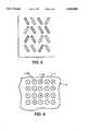
- FIG. 5is an example of incorporating the color data glyphs of the present invention within geometric-based data glyphs.
- FIG. 6shows a technique of printing color patches against a field of a color which is the average of the colors forming the information-bearing test patches.
- a method of creating a document bearing digital information on a surfacecomprising bits in a first state and bits in a second state arranged in a predetermined relative order.
- Each bit of the digital informationis assigned to one of a set of small areas on the surface, the small areas being regularly spaced along an axis on the surface.
- the bitsare assigned to the small areas along the axis in the predetermined relative order.
- For each bit in the first statea color patch of a first color is printed in the assigned small area.
- a color patch of a second coloris printed in the assigned small area.
- the color patchesare printed contiguously on the surface along the axis.
- a method of creating a document bearing digital information on a surfacecomprising bits in a first state and bits in a second state arranged in a predetermined relative order.
- Each bit of the digital informationis assigned to one of a set of small areas on the surface, the small areas being regularly spaced along an axis on the surface.
- the bitsare assigned to the small areas along the axis in the predetermined relative order.
- For each bit in the first statea color patch of a first color is printed in the assigned small area.
- a color patch of a second coloris printed in the assigned small area.
- a color patch of a third coloris printed on the surface, the third color being located in color space on a vector between the first color and the second color.
- a method of reading a document bearing digital information on a surfacecomprising color patches regularly spaced along an axis on the surface, the color patches comprising color patches of a first color and color patches of a second color, arranged along the axis in a predetermined relative order. Local concentrations of pixel areas of the first color are detected in the document. A location of the first color in color space is determined. A location of the second color in color space is determined, the second color being of a second predetermined relationship in color space with the first color. Local concentrations of pixel areas of the second color are detected in the document.
- Spatial relationshipsare determined in the document, of the local concentrations of pixel areas of the first color and the local concentrations of pixel areas of the second color.
- Binary datais derived from the spatial relationships of the local concentrations of pixel areas of the first color and the local concentrations of pixel areas of the second color.
- FIG. 1is a simple systems diagram showing the basic technique of rendering binary digital data according to the present invention.
- a stream of binary data to be stored on a surfaceis in the form of a series of 1 bits and 0 bits.
- the meaning of a particular set of binary datais derived from the relative positions of 1's and 0's in a stream. For example, within each 8-bit byte in the data stream, the particular combination of 1's and 0's can be interpreted by external means as representing an ASCII character, or be assigned some other meaning as is known in the art.
- a stream of binary data desired to be rendered on a hard-copy sheetis fed through a control program 99 which controls a color printer 100, as shown.
- the color printeris capable of creating small marks of predetermined desired color in small areas on a substrate such a sheet of paper.
- the binary data stream such as that illustratedis in effect translated into a sequence of small colored areas on a sheet S. As shown in FIG. 1, the relatively heavy cross-hatching in certain portions of the image on sheet S represents color patches of one color, while the lighter cross-hatching is intended to represent a color patch of a different color.
- sequence of color patchesare aligned along a single axis and that, comparing the original data to the resulting color patches on the sheet S, the relatively darker patches correspond to the 1's in the data stream while the lighter areas correspond to 0's in the data stream.
- the color patchesbe aligned along a axis, or at least follow some other organizing principle, because the important information rendered in the color patches derives from the relative order of 1's and 0's. Different colors can be assigned, as desired, to represent either 1's or 0's in the data as desired for a particular application.
- FIG. 2shows an example set of color patches representing binary data when a series of axes of color patches are printed contiguously on a sheet S.
- the color patchesare intended to take up only a portion of the illustrated portion of the sheet S.
- different patches of different colorstogether form a larger generally-colored area.
- such a combination of color patches of different colorsmay to a casual observer optically blend into a single hue.
- each individual color patchsuch as singled out as P in FIG. 2 may have a dimension of 5 ⁇ 5 pixels, making each color patch 1/60" on each side.
- any particular color or hue which can be printedcan be expressed in terms of a combination of different amounts of three combined primary colors.
- the primary colorsare typically subtractive primary colors such as magenta, yellow, and cyan; for machine sensing of colors, the primary colors are typically additive primary colors such as red, green, and blue.
- red, green, and blueFor the present example, it is assumed that any particular color printed by a color digital printer will include red, green, and blue components to various extents, as would be detected by digital scanning equipment.
- FIG. 3shows an example three-dimensional color space with the three subtractive primary colors blue, green, and red represented by axes in three-dimensional space: as is well-known, the farther from the origin one moves along a particular axis the more of that particular primary color will be apparent.
- color cis derived from a combination of a plurality of primary colors.
- the location in color space of color cis shown to lie on a particular vector of a certain length, and at either end of this vector are points in the color space which represent predetermined deviations from the basic color c. If the orientation of the vector is given as v 0 , one end of vector v 0 can be expressed as c+ ⁇ v 0 , while the other end of the vector v 0 can be expressed as c - ⁇ v 0 .
- the colorsare aligned along vector v 0 so that the basic color c can be seen to represent an "average" of the two colors represented by c+ ⁇ v 0 and c- ⁇ v 0 .
- the two colors of the color patchesbe roughly equidistant in color space from the desired average color c. It is further desirable that the relationship of the two colors, expressed as the orientation of the vector v 0 and the distance of the scalar ⁇ , be always constant when rendering binary data, regardless of the specific location in color space of the desired average color c. That is, various esthetic considerations going to the overall look of the image to be printed may mandate that a particular area be colored red, green, or whatever; the absolute value of the average color c in color space is preferably immaterial, and can be chosen from almost the entire color space of which the printer is capable.
- the two colors which are derived from the desired average color calways be of the same relationship to each other, such as by being oriented along the same vector direction of v 0 , and always separated from the average color c by the same scalar ⁇ .
- the desired separation of first colors and second colorscan be accomplished.
- the value of the scalar c zshould be sufficient for photosensitive equipment, such as a scanner, to be able to distinguish from the first color and the second color readily at the necessary resolution.
- the average color rendered on the page, and visible to the human eyeshould be deemed merely the carrier of information, and the color deviations of neighboring color patches being a modulation of the carrier.
- the orientation of vector v 0 and/or the scalar ⁇may be desirable to select the orientation of vector v 0 and/or the scalar ⁇ based on the absolute value of the desired average color c.
- Different average colors cmay be reproduced or detected with different peculiarities or common errors when printed or scanned on certain types of equipment. For example, given a certain set of printing and/or scanning equipment, the rendering of the precisely desired amount of yellow is difficult to obtain; in such a case, the lack of accuracy in printing or detecting yellow could be compensated for by using a value of a which increases depending on the amount of yellow in the average color c. In this way, the large difference in color-space among color patches (caused by the large ⁇ ) compensates for the lack of optical acuity in detecting yellow. For colors which are relatively easy for the scanner to discriminate, such as red, a smaller value of c t will suffice, and a smaller c z will be less conspicuous in a printed document.
- the color space relationship in FIG. 3represents a binary coding system.
- This binary coding systemcan be generalized into an N-ary system by providing, intersecting the desired average color c, a plurality of vectors v 0 , v 1 , v 2 . . . extending each in a different direction along some scalar a from the average color c.
- N-ary systemswill require relatively demanding color resolution of input scanning equipment.
- the different color patchesare preferably in the form of contiguous squares, but is also possibly desirable, for purposes of clarity, to separate individual color patches by small areas of blank space, or alternately make each color patch in the form of a discrete image, such as a round dot or even a small alphanumeric character, as shown in FIG. 4, where the different shading of each character represents a different color.
- each individual color patchin the form of a geometric glyph, such as described in the patents referenced above, wherein the shape or linear orientation of each glyph determines whether it is assigned a 1 or 0 value, as shown in FIG. 5, where the different shading of each character represents a different color.
- the shading of glyphs in FIG. 5that the relative colors of neighboring glyphs are independent of the orientations of neighboring glyphs.
- the geometry-based glyphscan be used to render one set of data, while the relative colors of neighboring glyphs render another set of digital data.
- One advantage of combining the color-based glyphs of the present invention with geometry-based glyphs as described in the above-referenced patentsis that one could create documents which provide two dimensions of digital data (both geometric-glyph data and color-glyph data) when the document is printed in color, but which sacrifice the color data, such as for security purposes, if the document is copied or printed on monochrome equipment.
- a reading program receiving scanned-in hard-copy data containing color glyphscan utilize the following basic steps to extract the desired binary information:
- the scanned-in document, converted to digital pixel data,is analyzed for glyph-bearing data.
- the equipmentcan be programmed to always place glyph-bearing images in a known area of the hard copy image.
- the form itselfmay include glyph-bearing data in a predetermined location on the form which customers mail in.
- the systemcould be made sensitive to particular average colors on scanned-in documents, signaling generally that they include glyph-bearing color patches therein.
- the average color c of the glyph-bearing portion of the imageis determined, basically by averaging the color space values over a relatively large set of small areas on the surface corresponding to image pixels. Obviously, the average color of a greenish area will have a very high vector of green signals, and relatively small values of blue and red signals.
- the colors of the first color patches and the second color patchescan be determined arithmetically.
- the scalar deviation of plus or minus c zis constant, along a vector v 0 of an orientation which is also constant for the system. Therefore, once the average color c is determined, the system can calculate where the pixels having the first color or the second color will appear in the color space.
- the systempolls the pixel data again, this time being sensitive to small patch-size concentrations of pixels which are of the predetermined relationship (c+ ⁇ 0 or c- ⁇ v 0 ) to the average color c.
- the absolute value of the average color c in color spaceis immaterial: what matters is the local deviations from the average color c.
- the pixels forming the glyph-bearing color spaceare then analyzed for local, patch-sized concentrations of pixels of the first color and concentrations of pixels of the second color, each respectively being assigned a binary value of 1 or 0 depending on the original parameters of the system. In this way, a stream of binary data can be isolated, and used as desired.
- Techniques for optically detecting individual color patches within a given area, and assigning meanings to those patches based on their positions within an area,are known in the art, particularly from known techniques relevant to geometric glyphs, as shown, for example, in the geometric glyph patents referenced above.
- the patchesshould be of such a size as to be compatible with the expected resolution of scanning equipment which will read the color glyphs. If the color patches are too small relative to the resolution of the optical scanning equipment, there will obviously be a great deal of error: for example, if the optical scanning equipment has a resolution of 200 pixels per inch, feeding in a document having contiguous color patches spaced 300 to the inch will cause the photosensors in the optical scanner to very often receive light from two color patches simultaneously.
- the optical scanning equipmentmay not recognize that a photosensor (such as in a linear CCD) is looking at two color patches at a given moment, and not one; further, if one color patch being observed is of a first color and the other color patch being simultaneously observed is of the second color, the two color patches reflecting into a single photosensor will cause the individual colors to average out.
- the color patchesshould be printed in a manner which can minimize the opportunity for such errors at the optical scanning stage.
- One technique for minimizing such errors in the scanning stageis to space color patches of the first color or second color from each other, to minimize the chance that a single photosensor in an optical scanner will simultaneously view two color patches.
- one technique for optically separating the color patchesis to provide a reasonably large white space between the color patches.
- the color patches of the first color or second colorcan be printed as "islands" in a field of the average color.
- FIG. 6An example of this technique is shown in FIG. 6: the individual information-bearing color patches, here shown as being of colors for either the 1-bits or 0-bits of binary data, are printed as round dots.
- the 1 color patchesare of the color c+ ⁇ v 0
- the 0 color patchesare of the color c- ⁇ v 0
- the various color patchesare spaced widely apart to ensure that one individual photosensor in optical scanning equipment will have a low risk of viewing two patches simultaneously.
- the amount of surface area on the sheet S on which the average color c is establishedbe made as small as necessary for enabling the system to distinguish between the different types of color patches.
- the arrangement shown in FIG. 6could be embodied in a rendering of a color photograph: any area in the photograph of a minimum size of a uniform color could be used as the "carrier" area.
- a more sophisticated systemcould be able to identify local average colors within a complex color image, and then identify the information bearing patches within the local areas of average colors. In this way, a single document may include a number of different average colors in different areas.
- a reading systemmay already have the underlying carrier data (such as of a color photograph) pre-stored in memory, and can just compare the data from a scanned-in document to derive the data-bearing color patches.
Landscapes
- Physics & Mathematics (AREA)
- Engineering & Computer Science (AREA)
- General Physics & Mathematics (AREA)
- Theoretical Computer Science (AREA)
- Health & Medical Sciences (AREA)
- Electromagnetism (AREA)
- General Health & Medical Sciences (AREA)
- Toxicology (AREA)
- Artificial Intelligence (AREA)
- Computer Vision & Pattern Recognition (AREA)
- Facsimile Image Signal Circuits (AREA)
- Image Processing (AREA)
Abstract
Description
Claims (8)
Priority Applications (2)
| Application Number | Priority Date | Filing Date | Title |
|---|---|---|---|
| US08/534,521US5684885A (en) | 1995-09-27 | 1995-09-27 | Binary glyph codes based on color relationships |
| JP8247931AJPH09134125A (en) | 1995-09-27 | 1996-09-19 | Document creation method and document reading method |
Applications Claiming Priority (1)
| Application Number | Priority Date | Filing Date | Title |
|---|---|---|---|
| US08/534,521US5684885A (en) | 1995-09-27 | 1995-09-27 | Binary glyph codes based on color relationships |
Publications (1)
| Publication Number | Publication Date |
|---|---|
| US5684885Atrue US5684885A (en) | 1997-11-04 |
Family
ID=24130428
Family Applications (1)
| Application Number | Title | Priority Date | Filing Date |
|---|---|---|---|
| US08/534,521Expired - Fee RelatedUS5684885A (en) | 1995-09-27 | 1995-09-27 | Binary glyph codes based on color relationships |
Country Status (2)
| Country | Link |
|---|---|
| US (1) | US5684885A (en) |
| JP (1) | JPH09134125A (en) |
Cited By (51)
| Publication number | Priority date | Publication date | Assignee | Title |
|---|---|---|---|---|
| US5946414A (en)* | 1998-08-28 | 1999-08-31 | Xerox Corporation | Encoding data in color images using patterned color modulated image regions |
| WO1999034277A3 (en)* | 1997-12-24 | 1999-11-11 | Interval Research Corp | Printable interfaces and digital linkmarks |
| US6000621A (en)* | 1995-12-21 | 1999-12-14 | Xerox Corporation | Tilings of mono-code and dual-code embedded data pattern strips for robust asynchronous capture |
| US6116507A (en)* | 1994-12-16 | 2000-09-12 | Olympus Optical Co., Ltd. | Information reproduction system for reproducing multimedia information recorded in the form of an optically readable dot code pattern wherein the optical readable dot code comprises address dots |
| US6141441A (en)* | 1998-09-28 | 2000-10-31 | Xerox Corporation | Decoding data from patterned color modulated image regions in a color image |
| US6164541A (en)* | 1997-10-10 | 2000-12-26 | Interval Research Group | Methods and systems for providing human/computer interfaces |
| US6256638B1 (en) | 1998-04-14 | 2001-07-03 | Interval Research Corporation | Printable interfaces and digital linkmarks |
| US6262711B1 (en) | 1995-08-03 | 2001-07-17 | Interval Research Corporation | Computerized interactor systems and method for providing same |
| US6325420B1 (en) | 1998-08-17 | 2001-12-04 | Inspectron Corporation | Method for embedding non-intrusive encoded data in printed matter and system for reading same |
| US20020031241A1 (en)* | 2001-02-02 | 2002-03-14 | Eiji Kawaguchi | Method and computer program product for hiding information in an indexed color image |
| US6411994B2 (en) | 1997-10-07 | 2002-06-25 | Interval Research Corporation | Interface system for providing content using context hotspots |
| US6439459B1 (en) | 1997-10-07 | 2002-08-27 | Interval Research Corporation | Methods and systems for providing human/computer interfaces |
| US6457651B2 (en)* | 1999-10-01 | 2002-10-01 | Xerox Corporation | Dual mode, dual information, document bar coding and reading system |
| US20030052179A1 (en)* | 2001-09-17 | 2003-03-20 | Mark Pinson | Machine-readable symbol and related method |
| US20030058477A1 (en)* | 2001-09-25 | 2003-03-27 | Brunk Hugh L. | Embedding digital watermarks in spot colors |
| US20030095268A1 (en)* | 2001-10-11 | 2003-05-22 | Uribe Gerardo Caracas | System for storing digital data on sheets using a color printer |
| US20030121978A1 (en)* | 2000-07-14 | 2003-07-03 | Rubin Kim T. | Compact matrix code and one-touch device and method for code reading |
| US20030225700A1 (en)* | 2002-03-14 | 2003-12-04 | Guillermo Lao | System and method for graphical rights expressions |
| US6674886B2 (en) | 1998-11-03 | 2004-01-06 | Digimarc Corporation | Method and system for recognizing security documents |
| EP1345193A3 (en)* | 1998-01-12 | 2004-05-26 | Jura-Trade Kereskedelmi KFT | Anti-counterfeiting decoding method and apparatus |
| US20040200904A1 (en)* | 2001-09-17 | 2004-10-14 | Mark Pinson | Machine-readable symbol and related method |
| US20040240704A1 (en)* | 2000-04-19 | 2004-12-02 | Reed Alastair M. | Applying digital watermarks using printing process correction |
| US6869023B2 (en) | 2002-02-12 | 2005-03-22 | Digimarc Corporation | Linking documents through digital watermarking |
| US6940486B2 (en) | 1995-08-03 | 2005-09-06 | Vulcan Patents Llc | Computerized interactor systems and methods for providing same |
| US6972867B1 (en)* | 2000-11-10 | 2005-12-06 | Xerox Corporation | Patch codes for color calibration job identification encoding |
| US20050285761A1 (en)* | 2004-06-28 | 2005-12-29 | Microsoft Corporation | System and method for encoding high density geometric symbol set |
| US20060039016A1 (en)* | 2004-08-23 | 2006-02-23 | Harrison Shelton E Jr | Polychromatic encoding system, method and device |
| US20060072778A1 (en)* | 2004-09-28 | 2006-04-06 | Xerox Corporation. | Encoding invisible electronic information in a printed document |
| US20060072781A1 (en)* | 2004-09-28 | 2006-04-06 | Harrington Steven J | Encoding invisible electronic information in a printed document |
| US7039214B2 (en) | 1999-11-05 | 2006-05-02 | Digimarc Corporation | Embedding watermark components during separate printing stages |
| US7044395B1 (en) | 1993-11-18 | 2006-05-16 | Digimarc Corporation | Embedding and reading imperceptible codes on objects |
| US7328851B1 (en)* | 2006-10-31 | 2008-02-12 | Xerox Corporation | Machine-readable code format |
| US7694887B2 (en) | 2001-12-24 | 2010-04-13 | L-1 Secure Credentialing, Inc. | Optically variable personalized indicia for identification documents |
| US7712673B2 (en) | 2002-12-18 | 2010-05-11 | L-L Secure Credentialing, Inc. | Identification document with three dimensional image of bearer |
| US7728048B2 (en) | 2002-12-20 | 2010-06-01 | L-1 Secure Credentialing, Inc. | Increasing thermal conductivity of host polymer used with laser engraving methods and compositions |
| US7744002B2 (en) | 2004-03-11 | 2010-06-29 | L-1 Secure Credentialing, Inc. | Tamper evident adhesive and identification document including same |
| US7744001B2 (en) | 2001-12-18 | 2010-06-29 | L-1 Secure Credentialing, Inc. | Multiple image security features for identification documents and methods of making same |
| US7789311B2 (en) | 2003-04-16 | 2010-09-07 | L-1 Secure Credentialing, Inc. | Three dimensional data storage |
| US7793846B2 (en) | 2001-12-24 | 2010-09-14 | L-1 Secure Credentialing, Inc. | Systems, compositions, and methods for full color laser engraving of ID documents |
| US7798413B2 (en) | 2001-12-24 | 2010-09-21 | L-1 Secure Credentialing, Inc. | Covert variable information on ID documents and methods of making same |
| US7804982B2 (en) | 2002-11-26 | 2010-09-28 | L-1 Secure Credentialing, Inc. | Systems and methods for managing and detecting fraud in image databases used with identification documents |
| US7824029B2 (en) | 2002-05-10 | 2010-11-02 | L-1 Secure Credentialing, Inc. | Identification card printer-assembler for over the counter card issuing |
| US20100282851A1 (en)* | 2009-05-06 | 2010-11-11 | Xerox Corporation | Method for encoding and decoding data in a color barcode pattern |
| US20100282856A1 (en)* | 2009-05-06 | 2010-11-11 | Xerox Corporation | Method for encoding and decoding data in a color barcode pattern |
| US7953112B2 (en) | 1997-10-09 | 2011-05-31 | Interval Licensing Llc | Variable bandwidth communication systems and methods |
| US20110192894A1 (en)* | 2010-02-09 | 2011-08-11 | Xerox Corporation | Method for one-step document categorization and separation |
| US8010632B2 (en) | 1993-11-18 | 2011-08-30 | Digimarc Corporation | Steganographic encoding for video and images |
| EP2280370A3 (en)* | 2006-10-31 | 2011-12-14 | Xerox Corporation | Method for printing machine-readable information with fluorescent materials |
| US20120027264A1 (en)* | 2008-12-05 | 2012-02-02 | Kabushiki Kaisha Toshiba | Image processing method and image processing apparatus |
| US8509137B2 (en) | 1997-10-09 | 2013-08-13 | Interval Licensing Llc | Method and apparatus for sending presence messages |
| USD836001S1 (en) | 2016-03-04 | 2018-12-18 | Discovery Inc. | Bar code for a pouch |
Families Citing this family (2)
| Publication number | Priority date | Publication date | Assignee | Title |
|---|---|---|---|---|
| JP3022462B2 (en) | 1998-01-13 | 2000-03-21 | 興和株式会社 | Vibration wave encoding method and decoding method |
| KR100697879B1 (en)* | 2005-08-17 | 2007-03-23 | 백기영 | How to encrypt and decrypt data using pixels |
Citations (13)
| Publication number | Priority date | Publication date | Assignee | Title |
|---|---|---|---|---|
| US3176141A (en)* | 1961-02-24 | 1965-03-30 | Ohio Commw Eng Co | Information reading circuit network |
| US3196393A (en)* | 1961-02-09 | 1965-07-20 | Ohio Commw Eng Co | Input device for data processing system |
| US3938088A (en)* | 1971-12-30 | 1976-02-10 | Xerox Corporation | Character coding and recognition system |
| US4488679A (en)* | 1982-11-01 | 1984-12-18 | Western Publishing Company, Inc. | Code and reading system |
| US4656345A (en)* | 1984-09-27 | 1987-04-07 | Tokyo Electric Co., Ltd. | Bar code reading apparatus |
| JPS63254586A (en)* | 1987-04-10 | 1988-10-21 | Toru Sugita | Information recording method and recording medium using the same |
| US5083816A (en)* | 1990-07-06 | 1992-01-28 | Engineered Data Products, Inc. | Machine and human readable label |
| US5091966A (en)* | 1990-07-31 | 1992-02-25 | Xerox Corporation | Adaptive scaling for decoding spatially periodic self-clocking glyph shape codes |
| US5221833A (en)* | 1991-12-27 | 1993-06-22 | Xerox Corporation | Methods and means for reducing bit error rates in reading self-clocking glyph codes |
| US5245165A (en)* | 1991-12-27 | 1993-09-14 | Xerox Corporation | Self-clocking glyph code for encoding dual bit digital values robustly |
| US5291243A (en)* | 1993-02-05 | 1994-03-01 | Xerox Corporation | System for electronically printing plural-color tamper-resistant documents |
| US5315098A (en)* | 1990-12-27 | 1994-05-24 | Xerox Corporation | Methods and means for embedding machine readable digital data in halftone images |
| US5369261A (en)* | 1992-02-12 | 1994-11-29 | Shamir; Harry | Multi-color information encoding system |
- 1995
- 1995-09-27USUS08/534,521patent/US5684885A/ennot_activeExpired - Fee Related
- 1996
- 1996-09-19JPJP8247931Apatent/JPH09134125A/enactivePending
Patent Citations (13)
| Publication number | Priority date | Publication date | Assignee | Title |
|---|---|---|---|---|
| US3196393A (en)* | 1961-02-09 | 1965-07-20 | Ohio Commw Eng Co | Input device for data processing system |
| US3176141A (en)* | 1961-02-24 | 1965-03-30 | Ohio Commw Eng Co | Information reading circuit network |
| US3938088A (en)* | 1971-12-30 | 1976-02-10 | Xerox Corporation | Character coding and recognition system |
| US4488679A (en)* | 1982-11-01 | 1984-12-18 | Western Publishing Company, Inc. | Code and reading system |
| US4656345A (en)* | 1984-09-27 | 1987-04-07 | Tokyo Electric Co., Ltd. | Bar code reading apparatus |
| JPS63254586A (en)* | 1987-04-10 | 1988-10-21 | Toru Sugita | Information recording method and recording medium using the same |
| US5083816A (en)* | 1990-07-06 | 1992-01-28 | Engineered Data Products, Inc. | Machine and human readable label |
| US5091966A (en)* | 1990-07-31 | 1992-02-25 | Xerox Corporation | Adaptive scaling for decoding spatially periodic self-clocking glyph shape codes |
| US5315098A (en)* | 1990-12-27 | 1994-05-24 | Xerox Corporation | Methods and means for embedding machine readable digital data in halftone images |
| US5221833A (en)* | 1991-12-27 | 1993-06-22 | Xerox Corporation | Methods and means for reducing bit error rates in reading self-clocking glyph codes |
| US5245165A (en)* | 1991-12-27 | 1993-09-14 | Xerox Corporation | Self-clocking glyph code for encoding dual bit digital values robustly |
| US5369261A (en)* | 1992-02-12 | 1994-11-29 | Shamir; Harry | Multi-color information encoding system |
| US5291243A (en)* | 1993-02-05 | 1994-03-01 | Xerox Corporation | System for electronically printing plural-color tamper-resistant documents |
Non-Patent Citations (2)
| Title |
|---|
| Network and Internetwork Security Principles and Practice by William Stallings, Ph.D (1995) pp. 27 28; 452; 456. IEEE Press.* |
| Network and Internetwork Security Principles and Practice by William Stallings, Ph.D (1995) pp. 27-28; 452; 456. IEEE Press. |
Cited By (83)
| Publication number | Priority date | Publication date | Assignee | Title |
|---|---|---|---|---|
| US8010632B2 (en) | 1993-11-18 | 2011-08-30 | Digimarc Corporation | Steganographic encoding for video and images |
| US7044395B1 (en) | 1993-11-18 | 2006-05-16 | Digimarc Corporation | Embedding and reading imperceptible codes on objects |
| US6116507A (en)* | 1994-12-16 | 2000-09-12 | Olympus Optical Co., Ltd. | Information reproduction system for reproducing multimedia information recorded in the form of an optically readable dot code pattern wherein the optical readable dot code comprises address dots |
| US6131807A (en)* | 1994-12-16 | 2000-10-17 | Olympus Optical Co., Ltd. | Information recording medium and information reproduction system |
| US7545359B1 (en) | 1995-08-03 | 2009-06-09 | Vulcan Patents Llc | Computerized interactor systems and methods for providing same |
| US8154511B2 (en) | 1995-08-03 | 2012-04-10 | Vintell Applications Ny, Llc | Computerized interactor systems and methods for providing same |
| US6940486B2 (en) | 1995-08-03 | 2005-09-06 | Vulcan Patents Llc | Computerized interactor systems and methods for providing same |
| US6262711B1 (en) | 1995-08-03 | 2001-07-17 | Interval Research Corporation | Computerized interactor systems and method for providing same |
| US6000621A (en)* | 1995-12-21 | 1999-12-14 | Xerox Corporation | Tilings of mono-code and dual-code embedded data pattern strips for robust asynchronous capture |
| US7177954B1 (en) | 1997-10-07 | 2007-02-13 | Vulcan Patents Llc | Interface system using hotspots |
| US6411994B2 (en) | 1997-10-07 | 2002-06-25 | Interval Research Corporation | Interface system for providing content using context hotspots |
| US6439459B1 (en) | 1997-10-07 | 2002-08-27 | Interval Research Corporation | Methods and systems for providing human/computer interfaces |
| US6540141B1 (en) | 1997-10-07 | 2003-04-01 | Interval Research Corporation | Methods and systems for providing human/computer interfaces |
| US6587859B2 (en) | 1997-10-07 | 2003-07-01 | Interval Research Corporation | Printable interfaces and digital linkmarks |
| US7953112B2 (en) | 1997-10-09 | 2011-05-31 | Interval Licensing Llc | Variable bandwidth communication systems and methods |
| US8509137B2 (en) | 1997-10-09 | 2013-08-13 | Interval Licensing Llc | Method and apparatus for sending presence messages |
| US8416806B2 (en) | 1997-10-09 | 2013-04-09 | Interval Licensing Llc | Variable bandwidth communication systems and methods |
| US6164541A (en)* | 1997-10-10 | 2000-12-26 | Interval Research Group | Methods and systems for providing human/computer interfaces |
| WO1999034277A3 (en)* | 1997-12-24 | 1999-11-11 | Interval Research Corp | Printable interfaces and digital linkmarks |
| EP1345193A3 (en)* | 1998-01-12 | 2004-05-26 | Jura-Trade Kereskedelmi KFT | Anti-counterfeiting decoding method and apparatus |
| US6256638B1 (en) | 1998-04-14 | 2001-07-03 | Interval Research Corporation | Printable interfaces and digital linkmarks |
| US6354630B1 (en)* | 1998-08-17 | 2002-03-12 | Inspectron Corporation | Method for embedding non-intrusive encoded data in printed matter |
| US6325420B1 (en) | 1998-08-17 | 2001-12-04 | Inspectron Corporation | Method for embedding non-intrusive encoded data in printed matter and system for reading same |
| US5946414A (en)* | 1998-08-28 | 1999-08-31 | Xerox Corporation | Encoding data in color images using patterned color modulated image regions |
| US6141441A (en)* | 1998-09-28 | 2000-10-31 | Xerox Corporation | Decoding data from patterned color modulated image regions in a color image |
| US6674886B2 (en) | 1998-11-03 | 2004-01-06 | Digimarc Corporation | Method and system for recognizing security documents |
| US6457651B2 (en)* | 1999-10-01 | 2002-10-01 | Xerox Corporation | Dual mode, dual information, document bar coding and reading system |
| US7039214B2 (en) | 1999-11-05 | 2006-05-02 | Digimarc Corporation | Embedding watermark components during separate printing stages |
| US20040240704A1 (en)* | 2000-04-19 | 2004-12-02 | Reed Alastair M. | Applying digital watermarks using printing process correction |
| US20030121978A1 (en)* | 2000-07-14 | 2003-07-03 | Rubin Kim T. | Compact matrix code and one-touch device and method for code reading |
| US6830197B2 (en)* | 2000-07-14 | 2004-12-14 | Intellidot Corporation | Compact matrix code and one-touch device and method for code reading |
| US6601772B1 (en) | 2000-07-14 | 2003-08-05 | Intellidot Corporation | Compact matrix code and one-touch device and method for code reading |
| US6972867B1 (en)* | 2000-11-10 | 2005-12-06 | Xerox Corporation | Patch codes for color calibration job identification encoding |
| US7436549B2 (en) | 2000-11-10 | 2008-10-14 | Xerox Corporation | Patch codes for color calibration job identification encoding |
| US20060028699A1 (en)* | 2000-11-10 | 2006-02-09 | Xerox Corporation | Patch codes for color calibration job identification encoding |
| US20020031241A1 (en)* | 2001-02-02 | 2002-03-14 | Eiji Kawaguchi | Method and computer program product for hiding information in an indexed color image |
| US6697498B2 (en)* | 2001-02-02 | 2004-02-24 | Asa Systems, Inc. | Method and computer program product for hiding information in an indexed color image |
| US20040200904A1 (en)* | 2001-09-17 | 2004-10-14 | Mark Pinson | Machine-readable symbol and related method |
| US20030052179A1 (en)* | 2001-09-17 | 2003-03-20 | Mark Pinson | Machine-readable symbol and related method |
| US7188778B2 (en) | 2001-09-17 | 2007-03-13 | Codemagic | Machine-readable symbol and related method |
| US20030058477A1 (en)* | 2001-09-25 | 2003-03-27 | Brunk Hugh L. | Embedding digital watermarks in spot colors |
| US6993149B2 (en)* | 2001-09-25 | 2006-01-31 | Digimarc Corporation | Embedding digital watermarks in spot colors |
| US20030095268A1 (en)* | 2001-10-11 | 2003-05-22 | Uribe Gerardo Caracas | System for storing digital data on sheets using a color printer |
| US8025239B2 (en) | 2001-12-18 | 2011-09-27 | L-1 Secure Credentialing, Inc. | Multiple image security features for identification documents and methods of making same |
| US7744001B2 (en) | 2001-12-18 | 2010-06-29 | L-1 Secure Credentialing, Inc. | Multiple image security features for identification documents and methods of making same |
| US7798413B2 (en) | 2001-12-24 | 2010-09-21 | L-1 Secure Credentialing, Inc. | Covert variable information on ID documents and methods of making same |
| US7793846B2 (en) | 2001-12-24 | 2010-09-14 | L-1 Secure Credentialing, Inc. | Systems, compositions, and methods for full color laser engraving of ID documents |
| US7980596B2 (en) | 2001-12-24 | 2011-07-19 | L-1 Secure Credentialing, Inc. | Increasing thermal conductivity of host polymer used with laser engraving methods and compositions |
| US7694887B2 (en) | 2001-12-24 | 2010-04-13 | L-1 Secure Credentialing, Inc. | Optically variable personalized indicia for identification documents |
| US6869023B2 (en) | 2002-02-12 | 2005-03-22 | Digimarc Corporation | Linking documents through digital watermarking |
| US9626668B2 (en) | 2002-03-14 | 2017-04-18 | Contentgaurd Holdings, Inc. | Rights expression profile system and method using templates |
| US20030225700A1 (en)* | 2002-03-14 | 2003-12-04 | Guillermo Lao | System and method for graphical rights expressions |
| US8108313B2 (en) | 2002-03-14 | 2012-01-31 | Contentguard Holdings, Inc. | Rights expression profile system and method using templates |
| US7359884B2 (en) | 2002-03-14 | 2008-04-15 | Contentguard Holdings, Inc. | Method and apparatus for processing usage rights expressions |
| US7824029B2 (en) | 2002-05-10 | 2010-11-02 | L-1 Secure Credentialing, Inc. | Identification card printer-assembler for over the counter card issuing |
| US7804982B2 (en) | 2002-11-26 | 2010-09-28 | L-1 Secure Credentialing, Inc. | Systems and methods for managing and detecting fraud in image databases used with identification documents |
| US7712673B2 (en) | 2002-12-18 | 2010-05-11 | L-L Secure Credentialing, Inc. | Identification document with three dimensional image of bearer |
| US7728048B2 (en) | 2002-12-20 | 2010-06-01 | L-1 Secure Credentialing, Inc. | Increasing thermal conductivity of host polymer used with laser engraving methods and compositions |
| US7789311B2 (en) | 2003-04-16 | 2010-09-07 | L-1 Secure Credentialing, Inc. | Three dimensional data storage |
| US7744002B2 (en) | 2004-03-11 | 2010-06-29 | L-1 Secure Credentialing, Inc. | Tamper evident adhesive and identification document including same |
| US7963449B2 (en) | 2004-03-11 | 2011-06-21 | L-1 Secure Credentialing | Tamper evident adhesive and identification document including same |
| US7751585B2 (en)* | 2004-06-28 | 2010-07-06 | Microsoft Corporation | System and method for encoding high density geometric symbol set |
| US20050285761A1 (en)* | 2004-06-28 | 2005-12-29 | Microsoft Corporation | System and method for encoding high density geometric symbol set |
| US8670168B1 (en) | 2004-08-23 | 2014-03-11 | Search And Social Media Partners Llc | Polychromatic encoding system, method and device |
| US7710598B2 (en) | 2004-08-23 | 2010-05-04 | Harrison Jr Shelton E | Polychromatic encoding system, method and device |
| US20060039016A1 (en)* | 2004-08-23 | 2006-02-23 | Harrison Shelton E Jr | Polychromatic encoding system, method and device |
| US7961905B2 (en) | 2004-09-28 | 2011-06-14 | Xerox Corporation | Encoding invisible electronic information in a printed document |
| US20080267515A1 (en)* | 2004-09-28 | 2008-10-30 | Xerox Corporation | Encoding invisible electronic information in a printed document |
| US7397584B2 (en) | 2004-09-28 | 2008-07-08 | Xerox Corporation | Encoding invisible electronic information in a printed document |
| US20060072778A1 (en)* | 2004-09-28 | 2006-04-06 | Xerox Corporation. | Encoding invisible electronic information in a printed document |
| US20060072781A1 (en)* | 2004-09-28 | 2006-04-06 | Harrington Steven J | Encoding invisible electronic information in a printed document |
| EP2280370A3 (en)* | 2006-10-31 | 2011-12-14 | Xerox Corporation | Method for printing machine-readable information with fluorescent materials |
| US7328851B1 (en)* | 2006-10-31 | 2008-02-12 | Xerox Corporation | Machine-readable code format |
| EP1918856A1 (en) | 2006-10-31 | 2008-05-07 | Xerox Corporation | Machine-readable code format |
| US20120027264A1 (en)* | 2008-12-05 | 2012-02-02 | Kabushiki Kaisha Toshiba | Image processing method and image processing apparatus |
| US8625857B2 (en)* | 2008-12-05 | 2014-01-07 | Kabushiki Kaisha Toshiba | Image processing method and image processing apparatus |
| US8100330B2 (en) | 2009-05-06 | 2012-01-24 | Xerox Corporation | Method for encoding and decoding data in a color barcode pattern |
| US8047447B2 (en) | 2009-05-06 | 2011-11-01 | Xerox Corporation | Method for encoding and decoding data in a color barcode pattern |
| US20100282856A1 (en)* | 2009-05-06 | 2010-11-11 | Xerox Corporation | Method for encoding and decoding data in a color barcode pattern |
| US20100282851A1 (en)* | 2009-05-06 | 2010-11-11 | Xerox Corporation | Method for encoding and decoding data in a color barcode pattern |
| US8453922B2 (en) | 2010-02-09 | 2013-06-04 | Xerox Corporation | Method for one-step document categorization and separation using stamped machine recognizable patterns |
| US20110192894A1 (en)* | 2010-02-09 | 2011-08-11 | Xerox Corporation | Method for one-step document categorization and separation |
| USD836001S1 (en) | 2016-03-04 | 2018-12-18 | Discovery Inc. | Bar code for a pouch |
Also Published As
| Publication number | Publication date |
|---|---|
| JPH09134125A (en) | 1997-05-20 |
Similar Documents
| Publication | Publication Date | Title |
|---|---|---|
| US5684885A (en) | Binary glyph codes based on color relationships | |
| US6457651B2 (en) | Dual mode, dual information, document bar coding and reading system | |
| US8111432B2 (en) | Infrared watermarking of photographic images by matched differential black strategies | |
| CA2057479C (en) | Support provided with a security element | |
| US8455087B2 (en) | Infrared encoding of security elements using standard xerographic materials with distraction patterns | |
| US7961905B2 (en) | Encoding invisible electronic information in a printed document | |
| EP2230088B1 (en) | High resolution scalable gloss effect | |
| US6753977B2 (en) | Machine-readable information embedded on a document | |
| EP2122534B1 (en) | Multiple resolution readable color array | |
| CN1183477C (en) | Highly reliable judicial color marking system | |
| EP2290621A2 (en) | Magnetic watermarking of a printed substrate by metameric rendering | |
| US6239818B1 (en) | Printing method and apparatus | |
| US20080180751A1 (en) | Variable guilloche and method | |
| EP4078451B1 (en) | Method and device for reading a two-dimensional encoded pattern applied on a non-uniform background | |
| US20090026753A1 (en) | Security deterrent mark and methods of forming the same | |
| WO2007059340A2 (en) | Product security pattern based on simultaneous color contrast | |
| US12220934B2 (en) | Method of printing authentication indicators with amplitude modulated halftone printing | |
| WO2006001793A9 (en) | Full color scanning protection of document | |
| EP2946341B1 (en) | Method of printing printed matter comprising an optically readable code | |
| JP3367959B2 (en) | Image processing apparatus and method | |
| KR102502692B1 (en) | method of identifying printed matter using identification mark in the printed matter | |
| US20050044371A1 (en) | Deterring counterfeiting using custom colored inks | |
| Bala et al. | Robust Processing of Color Target Measurements for Device Characterization |
Legal Events
| Date | Code | Title | Description |
|---|---|---|---|
| AS | Assignment | Owner name:XEROX CORPORATION, CONNECTICUT Free format text:ASSIGNMENT OF ASSIGNORS INTEREST;ASSIGNORS:CASS, TODD A.;MARIMONT, DAVID H.;REEL/FRAME:007699/0221 Effective date:19950919 | |
| FPAY | Fee payment | Year of fee payment:4 | |
| AS | Assignment | Owner name:BANK ONE, NA, AS ADMINISTRATIVE AGENT, ILLINOIS Free format text:SECURITY INTEREST;ASSIGNOR:XEROX CORPORATION;REEL/FRAME:013153/0001 Effective date:20020621 | |
| AS | Assignment | Owner name:JPMORGAN CHASE BANK, AS COLLATERAL AGENT, TEXAS Free format text:SECURITY AGREEMENT;ASSIGNOR:XEROX CORPORATION;REEL/FRAME:015134/0476 Effective date:20030625 Owner name:JPMORGAN CHASE BANK, AS COLLATERAL AGENT,TEXAS Free format text:SECURITY AGREEMENT;ASSIGNOR:XEROX CORPORATION;REEL/FRAME:015134/0476 Effective date:20030625 | |
| REMI | Maintenance fee reminder mailed | ||
| LAPS | Lapse for failure to pay maintenance fees | ||
| STCH | Information on status: patent discontinuation | Free format text:PATENT EXPIRED DUE TO NONPAYMENT OF MAINTENANCE FEES UNDER 37 CFR 1.362 | |
| FP | Lapsed due to failure to pay maintenance fee | Effective date:20051104 | |
| AS | Assignment | Owner name:XEROX CORPORATION, CONNECTICUT Free format text:RELEASE BY SECURED PARTY;ASSIGNOR:JPMORGAN CHASE BANK, N.A. AS SUCCESSOR-IN-INTEREST ADMINISTRATIVE AGENT AND COLLATERAL AGENT TO JPMORGAN CHASE BANK;REEL/FRAME:066728/0193 Effective date:20220822 |