US5684582A - Spectrophotometry - Google Patents
SpectrophotometryDownload PDFInfo
- Publication number
- US5684582A US5684582AUS08/471,617US47161795AUS5684582AUS 5684582 AUS5684582 AUS 5684582AUS 47161795 AUS47161795 AUS 47161795AUS 5684582 AUS5684582 AUS 5684582A
- Authority
- US
- United States
- Prior art keywords
- dispersive element
- path
- object area
- shells
- spectrophotometer
- Prior art date
- Legal status (The legal status is an assumption and is not a legal conclusion. Google has not performed a legal analysis and makes no representation as to the accuracy of the status listed.)
- Expired - Fee Related
Links
Images


Classifications
- G—PHYSICS
- G01—MEASURING; TESTING
- G01J—MEASUREMENT OF INTENSITY, VELOCITY, SPECTRAL CONTENT, POLARISATION, PHASE OR PULSE CHARACTERISTICS OF INFRARED, VISIBLE OR ULTRAVIOLET LIGHT; COLORIMETRY; RADIATION PYROMETRY
- G01J3/00—Spectrometry; Spectrophotometry; Monochromators; Measuring colours
- G01J3/46—Measurement of colour; Colour measuring devices, e.g. colorimeters
- G01J3/50—Measurement of colour; Colour measuring devices, e.g. colorimeters using electric radiation detectors
- G—PHYSICS
- G01—MEASURING; TESTING
- G01J—MEASUREMENT OF INTENSITY, VELOCITY, SPECTRAL CONTENT, POLARISATION, PHASE OR PULSE CHARACTERISTICS OF INFRARED, VISIBLE OR ULTRAVIOLET LIGHT; COLORIMETRY; RADIATION PYROMETRY
- G01J3/00—Spectrometry; Spectrophotometry; Monochromators; Measuring colours
- G01J3/02—Details
- G01J3/0202—Mechanical elements; Supports for optical elements
- G—PHYSICS
- G01—MEASURING; TESTING
- G01J—MEASUREMENT OF INTENSITY, VELOCITY, SPECTRAL CONTENT, POLARISATION, PHASE OR PULSE CHARACTERISTICS OF INFRARED, VISIBLE OR ULTRAVIOLET LIGHT; COLORIMETRY; RADIATION PYROMETRY
- G01J3/00—Spectrometry; Spectrophotometry; Monochromators; Measuring colours
- G01J3/02—Details
- G01J3/0256—Compact construction
- G—PHYSICS
- G01—MEASURING; TESTING
- G01J—MEASUREMENT OF INTENSITY, VELOCITY, SPECTRAL CONTENT, POLARISATION, PHASE OR PULSE CHARACTERISTICS OF INFRARED, VISIBLE OR ULTRAVIOLET LIGHT; COLORIMETRY; RADIATION PYROMETRY
- G01J3/00—Spectrometry; Spectrophotometry; Monochromators; Measuring colours
- G01J3/02—Details
- G01J3/0272—Handheld
- G—PHYSICS
- G01—MEASURING; TESTING
- G01J—MEASUREMENT OF INTENSITY, VELOCITY, SPECTRAL CONTENT, POLARISATION, PHASE OR PULSE CHARACTERISTICS OF INFRARED, VISIBLE OR ULTRAVIOLET LIGHT; COLORIMETRY; RADIATION PYROMETRY
- G01J3/00—Spectrometry; Spectrophotometry; Monochromators; Measuring colours
- G01J3/02—Details
- G01J3/0283—Details using a charging unit
- G—PHYSICS
- G01—MEASURING; TESTING
- G01J—MEASUREMENT OF INTENSITY, VELOCITY, SPECTRAL CONTENT, POLARISATION, PHASE OR PULSE CHARACTERISTICS OF INFRARED, VISIBLE OR ULTRAVIOLET LIGHT; COLORIMETRY; RADIATION PYROMETRY
- G01J3/00—Spectrometry; Spectrophotometry; Monochromators; Measuring colours
- G01J3/02—Details
- G01J3/0291—Housings; Spectrometer accessories; Spatial arrangement of elements, e.g. folded path arrangements
- G—PHYSICS
- G01—MEASURING; TESTING
- G01J—MEASUREMENT OF INTENSITY, VELOCITY, SPECTRAL CONTENT, POLARISATION, PHASE OR PULSE CHARACTERISTICS OF INFRARED, VISIBLE OR ULTRAVIOLET LIGHT; COLORIMETRY; RADIATION PYROMETRY
- G01J3/00—Spectrometry; Spectrophotometry; Monochromators; Measuring colours
- G01J3/02—Details
- G01J3/06—Scanning arrangements arrangements for order-selection
- G—PHYSICS
- G01—MEASURING; TESTING
- G01J—MEASUREMENT OF INTENSITY, VELOCITY, SPECTRAL CONTENT, POLARISATION, PHASE OR PULSE CHARACTERISTICS OF INFRARED, VISIBLE OR ULTRAVIOLET LIGHT; COLORIMETRY; RADIATION PYROMETRY
- G01J3/00—Spectrometry; Spectrophotometry; Monochromators; Measuring colours
- G01J3/12—Generating the spectrum; Monochromators
- G01J3/18—Generating the spectrum; Monochromators using diffraction elements, e.g. grating
- G—PHYSICS
- G01—MEASURING; TESTING
- G01J—MEASUREMENT OF INTENSITY, VELOCITY, SPECTRAL CONTENT, POLARISATION, PHASE OR PULSE CHARACTERISTICS OF INFRARED, VISIBLE OR ULTRAVIOLET LIGHT; COLORIMETRY; RADIATION PYROMETRY
- G01J3/00—Spectrometry; Spectrophotometry; Monochromators; Measuring colours
- G01J3/28—Investigating the spectrum
- G—PHYSICS
- G01—MEASURING; TESTING
- G01J—MEASUREMENT OF INTENSITY, VELOCITY, SPECTRAL CONTENT, POLARISATION, PHASE OR PULSE CHARACTERISTICS OF INFRARED, VISIBLE OR ULTRAVIOLET LIGHT; COLORIMETRY; RADIATION PYROMETRY
- G01J3/00—Spectrometry; Spectrophotometry; Monochromators; Measuring colours
- G01J3/46—Measurement of colour; Colour measuring devices, e.g. colorimeters
- G01J3/50—Measurement of colour; Colour measuring devices, e.g. colorimeters using electric radiation detectors
- G01J3/502—Measurement of colour; Colour measuring devices, e.g. colorimeters using electric radiation detectors using a dispersive element, e.g. grating, prism
- G—PHYSICS
- G01—MEASURING; TESTING
- G01J—MEASUREMENT OF INTENSITY, VELOCITY, SPECTRAL CONTENT, POLARISATION, PHASE OR PULSE CHARACTERISTICS OF INFRARED, VISIBLE OR ULTRAVIOLET LIGHT; COLORIMETRY; RADIATION PYROMETRY
- G01J3/00—Spectrometry; Spectrophotometry; Monochromators; Measuring colours
- G01J3/46—Measurement of colour; Colour measuring devices, e.g. colorimeters
- G01J3/52—Measurement of colour; Colour measuring devices, e.g. colorimeters using colour charts
- G01J3/524—Calibration of colorimeters
- G—PHYSICS
- G01—MEASURING; TESTING
- G01J—MEASUREMENT OF INTENSITY, VELOCITY, SPECTRAL CONTENT, POLARISATION, PHASE OR PULSE CHARACTERISTICS OF INFRARED, VISIBLE OR ULTRAVIOLET LIGHT; COLORIMETRY; RADIATION PYROMETRY
- G01J3/00—Spectrometry; Spectrophotometry; Monochromators; Measuring colours
- G01J3/28—Investigating the spectrum
- G01J2003/2866—Markers; Calibrating of scan
Definitions
- the present inventionrelates to spectrophotometry and more particularly to apparatus for measuring the spectrum of optical illumination at a plurality of successive wavelength increments.
- the inventionis especially suitable in use for color management to enable colors to be matched for consistency with accepted color standards and for balance so that images formed by color reprographics (especially by digital or computer controlled imaging techniques) can meet applicable standards.
- Spectrophotometry apparatus and methodswhich are practiced in accordance with the invention may also be useful in the calibration of radiant sources such as the screens of color monitors (phosphors of which are electronically activated to produce color images in such monitors.)
- the spectrometer apparatusmay also be used as a densitometer and generally as a color spectrometer for color matching purposes as for example in mixing of paints. Such color matching and density control have been called color management in the reprographics field.
- the inventionimproves the art of spectrophotometry by providing an instrument useful for measuring the spectrum of light which the instrument receives through the use of a dispersive element rotatable in angular increments, particularly increments corresponding to angular displacements of the shaft of a drive motor which effects movement of the dispersive element about an axis of rotation laterally displaced from the element.
- Opticsprovides a geometry which illuminates the dispersive element with light from a sample which enters the spectrophotometer at an object area.
- These opticsinclude an aperture which defines the object area and which is desirably in the form of a rectangular slit.
- the apertureforms the illumination into a beam which diverges as it propagates along a first path between the object area and the dispersive element, on a surface of which the beam is incident.
- the beamis then deflected (diffracted where the dispersive element is a grating, as is preferably the case).
- the deflected beampropagates along a second path to a photodetector at an image area which terminates the second path.
- a lens having an optical axisis disposed along the second path.
- the dispersion in the dispersive elementspatially distributes the illumination in accordance with its wavelength so that the chief ray of the illumination, which has a wavelength in the middle of each optical increment, extends along the optical axis regardless of the angular orientation of the dispersive element as it scans the wavelength of the illumination.
- the rays of wavelength at each end of the wavelength incrementsare at opposite sides of the beam and are focused at opposite ends of the image area by the lens.
- the entire spectral incrementis measured and translated into a corresponding electrical signal by the photodetector.
- an optical attenuating elementwhich moves with the dispersive element across the first path, intercepting and attenuating the beam as a function of the angular displacement corresponding to the wavelength increment which is being measured. Then signals at one end of the spectrum (the longer wavelength end) are reduced in amplitude, relative to the signals obtained from the short wavelength end, without the need for electronic means for controlling the dynamic range, thereby providing outputs from the photodetector which correspond to the color perception of light.
- the light entering the object areais diffuse and may be imaged at a Fourier transfer plane (focal plane) of a field lens at the object area.
- a shutterwhich moves with the dispersive element may be used as the attenuating element.
- the dispersive elementis desirably a plane diffraction grating which is operative in the -1 diffraction order to deflect the light in each wavelength increment so that the rays at the center wavelengths (chief rays) are generally along the optical axis of the lens.
- the opticspermits the grating to be rotated to a position where the zeroth order diffraction or specular reflection from the grating occurs and illuminates the photodetector.
- the spectrophotometermay be used to monitor the intensity of the illumination and to obtain the intensity characteristic of a luminescent source, for example, a computer monitor; the phosphors of which emit at different intensities depending upon the intensity of the electron beam which excites the phosphor in the monitor.
- the intensity characteristic of the monitormay be measured so that the monitor may be adjusted to provide accurate color balance across its entire image intensity range.
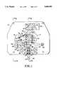
- FIG. 1is a plan view showing the arrangement of the optical and electro-optical components of spectrophotometer apparatus which is provided in accordance with the invention
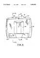
- FIG. 2is a perspective view illustrating a held-held and self-contained spectrophotometer which utilizes the spectrophotometry apparatus illustrated in FIG. 1;
- FIG. 3is a side view of the spectrophotometer shown in FIG. 2;
- FIG. 4is a front view of the spectrophotometer shown in FIGS. 2 and 3, the view being taken from the right in FIG. 3;
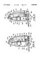
- FIG. 5is a sectional view which is taken along the line 5--5 in FIG. 4, and shows the spectrophotometer apparatus of FIG. 1 contained therein, also as viewed along the line 5--5 in FIG. 1;
- FIG. 6is a sectional view taken along the line 6--6 in FIG. 4 and also showing the spectrophotometer apparatus of FIG. 1 taken along the line 6--6 in FIG. 1;
- FIG. 7is a schematic diagram, in the form of a layout, of the components of the spectrophotometer apparatus shown in FIG. 1 in simplified form;
- FIG. 8is a view similar to FIG. 7 but with the dispersive element of the spectrophotometer angularly displaced to a position for specular reflection (zeroth order diffraction) of the light incident thereon;
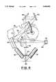
- FIG. 9is a view similar to FIG. 1, but showing the dispersive element and the arm mounting that element and a shutter carried on the arm in two different angular positions where two different wavelength increments of the spectrum of the illumination entering the spectrophotometer, which correspond to these two angular increments or steps, are measured;
- FIG. 10is a schematic diagram of an embodiment of the photodetector for selecting samples of smaller and larger size for spectral analysis.
- FIG. 1there is shown a top view of optical, electronic and electrical components of a spectrophotometer embodying the invention which components are mounted on a plate provided by a circuit board 10 of insulating material having on the bottom side thereof, electronic components, principally integrated circuit chips, which are connected by printed wiring to the electrical and electronic components on the board 10 and to a connector which connects, via a cable, the spectrophotometer to equipment with which it is used, such as a computer.
- the cableis sufficiently long and flexible to enable the spectrophotometer to be hand-held and portable.
- the connectoris not shown in the drawing to simplify the illustration.
- the componentsinclude a stepper motor 12 which is mounted on the bottom of the board and has a shaft 14 projecting through the board.
- the shaftis in frictional driving contact with an elastomeric, resilient layer 16 at an end of an arm 18 which is rotatable about an axis of a pivot 20 on the top of the board 10.
- the profile of the arm 18 at the end having the layeris circular, but may be made non-circular (cam shaped) to match the wavelength increments more closely to equal angular increments or steps, through which the shaft 14 turns when making a spectral response measurement.
- a dispersive elementwhich is preferably a diffraction grating 24, which has grating lines on a face 26 thereof. These grating lines may be provided by blazing and are designed in accordance with conventional grating design techniques to deflect with maximum energy in the -1 diffraction order. Other dispersive elements such as prisms and other diffractive orders may be used.
- the spectrophotometermay be used with the grating operative in the zeroth order where light incident on the face 26 is specularly deflected. While a reflection mode diffraction grating is preferred in this embodiment of the invention, another type of dispersive element may be used.
- the opticsmay also be usable in the transmission mode of the grating. However, the use of the transmission mode prevents the folding of the optical path and is not presently preferred, in the interest of providing a spectrophotometer of miniature size and weight.
- the herein illustrated spectrophotometermay be less than about 5 inches long and 5 inches wide and less than about two inches thick and have a weight of less than 1 pound thereby enabling it to be hand-held and portable.
- the spectrophotometeris responsive to light from a sample which is spaced in the vicinity of an entrance end thereof at a location indicated at 28 in FIG. 1. This sample area may be a patch or test region on a photograph or other image to be reproduced.
- the spectrometermay also be used to measure the color content (spectral characteristics) of radiating optical sources, such as electro-luminescent devices. Such sources may be the screens of computer monitors, which are cathode ray tubes having phosphors which are excited by electron beams; the phosphors being on the screens of the cathode ray tube of the monitor.
- reflective patches or materialsare to be analyzed for color or spectral content, they may be illuminated by lamps 30 and 32.
- Small lens end, incandescent lamp bulbsare preferably used as the lamps 30 and 32 to provide the illumination of a reflective sample.
- An object area of the spectrophotometeris defined by a aperture or object slit 34, which is preferably a rectangular slit aperture with the short dimension of the slit LD defining the width of the object area.
- the long axis or length of the rectangle of the apertureis perpendicular to the plane of FIG. 1.
- the object area and the apertureare co-extensive.
- the light which reaches the aperturearrives from the entire sample area in a region defined by LD along the one dimension thereof. This light is diffuse and enters the object area (the aperture 34) from multiple directions.
- the width of the object slit 34 and the image aperture (another rectangular slit) 64 which defines an image areadetermine the wavelength resolution.
- the width of the image slitis determined by the angular dispersive strength of the dispersive element and the focal length of the imaging lens.
- ⁇ 2⁇ m/(p cos ⁇ 2 ).
- the image slit 64 widthis the angular dispersion of the grating multiplied by the distance from the second principal plane of the lens to the image of the object slit 34.
- the image distanceis 36.94 mm
- the image slit widthis 0.44 mm for 10 nm resolution image side resolution.
- the total resolution of a spectrometeris the convolution of object-side and image-side wavelength resolutions.
- the optical throughput and resolutionis optimized when the object-side and image-side wavelength resolutions are matched. This is achieved when the width of the image of the object slit equals the physical size of the image slit 64. This means that the angular width (perpendicular to the diffraction grooves) of the object slit, and image slit when viewed from the principal planes of the lens, are equal.
- the height of the object slitis determined by four factors, the size of the emissive or illuminated sample area, the size of the optical elements (their apertures), the aberration tolerance of the system and the detector size.
- the aperture stop sizeis 12 mm and the object height is 9 mm.
- the dynamic range of the spectral measurementsmay be controlled using a shutter 36 which is mounted on the arm 18.
- a field lens 38on the inside of the aperture 34 across the object area.
- This field lensmay be a plano-convex lens having a focus at the location of the shutter 36.
- the shuttermoves across the Fourier transfer plane of the lens 38.
- the lens 38converts the angular distribution of light at the objects slit 34 into spatial distribution of intensity at the location where the shutter 36 interrupts the beam 44. Accordingly the shutter effects the spatial distribution of light from the sample area 28 uniformly.
- a variable neutral density filtermay be used as the attenuating element.
- a bracket 40supports the aperture 34 and another aperture 42 which serves as a baffle to restrict the size of a beam 44 of illumination, which diverges as the beam propagates away from the aperture 34 along a first path which terminates at the surface 26 of the grating 24.
- the length of this pathis such that the grating is substantially filled on the face 26 thereof, at least along the LD dimension of the beam.
- the beam path length between the object slit 34 and the face 26is effectively lengthened by means of optics including folding mirrors 46 and 48.
- mirrors 46 and 48are mounted on the top surface of the board 10 in a bracket 50 so that the beam path remains fixed, but sufficiently long to fill the face 26 of the grating.
- the chief (approximately central) ray 52 of the beam along the first path and the rays 54 and 56 spatially displaced at opposite ends of the dimension LDare indicated in FIG. 1.
- the beamis deflected by the grating 24 in accordance with the wavelength of the illumination by different amounts in accordance with the period of the grating (the distance between the grating lines) and the wavelength of the illumination.
- the period and the angle of incidence of the beam on the surface 24, for example as measured by the angle between a perpendicular to the surface 26 and the chief ray 52,is selected so that the chief ray 58 of the deflected beam 60 has a wavelength equal to the wavelength at the center of each spectral increment or step (corresponding to each angular step of rotation of the motor shaft 14) and this chief ray 58 is always, for each spectral increment regardless of the tilt of the grating 14, along a line which is imaged to a photodetector 62. This line is along a second optical path which is between the face 26 and the photodetector 62.
- the photodetectordefines an image area or may be used with an aperture 64, rectangular image slit discussed above, to define the image area of the spectrophotometer.
- the lens 66preferably an achromat lens 66, is mounted on the top of the board 10 and converges the deflected beam so that it substantially fills the aperture 64, with light from the spectral increment.
- the rays 68 and 70 along opposite sides of the deflected beamare of wavelengths at opposite ends of the wavelength increment. These rays are converged by the lens 66 which has one focus at the image area and the other, or conjugate, focus at the object slit 34.
- lateral chromatic aberrationmay be disregarded in the spectrophotometer design.
- Longitudinal chromatic aberrationmay be also be compensated since the path length between the face 26 of the grating and the lens 66 varies as the grating tilts.
- longitudinal chromatic aberrationmay also be compensated.
- the use of an achromat 66is preferred, since the achromat is designed to compensate for longitudinal aberration which may be present even with the automatic path length compensation due to the geometry of the beam along the first path from the object slit 34 to the grating 24.
- the incident chief ray and the diffracted chief rayare separated by 45°.
- a notch 71 in the arm 18serves as an indexing device to operate either a switch or a photo interrupter which provides a signal to the motor control circuitry when the motor is indexed to its start or home position.
- Each wavelength band or incrementis imaged at the image area and the photodetector provides an output level corresponding thereto.
- This output levelmay be digitized into a multi bit digital byte or number, for example, of 16 bits, which defines the spectral intensity with a resolution of approximately 65,000 levels.
- This digital numbermay be created by utilizing the output of the photodetector to control the frequency of an oscillator and to measure the number of counts or cycles or half-cycles of the oscillator's output (repetition rate) in a counter which provides the digitized spectral output for that increment or step.
- the output of the summing circuitis amplified in amplifiers 76 and 78.
- the amplifier 78has 3 times the gain of the amplifier 76 to compensate for the use of a photodetector area of 1/3 that of all three areas 62A, B and C together.
- the outputs from the amplifierare then applied to a signal processor and digitizer to obtain the digital signals corresponding to the spectral. This signal processor processes the analog signals and then digitizes them and provides the output to a computer or other data processor 82.
- the illumination at the red or high wavelength end of the bandis detected with greater efficiency by silicon photodetectors than the signals at the low or blue end of the band.
- incandescent lampshave greater spectral intensity in the red than the blue.
- a wide dynamic rangefor example, over 100 times larger at the red end than at the blue end may need to be accommodated in order to cover the actual intensities involved.
- the attenuating element 36comes into play. Then, at increments in the red end of the band, more attenuation is inserted than at the blue end of the band where the attenuation is minimal. This automatically compensates for the differences in intensity at opposite ends of the band and reduces the dynamic range which must be accommodated by the circuitry operative with the photodetector 62.
- Another method of normalizing the detected spectral intensityis use a analog to digital converter to sample and digitize the detected electrical signal from the photodetector.
- the conversion speed of the analog to digital converteris fast enough to digitize the electrical at least 16 times before the motor increments to the next spectral bin.
- Signals from each spectral binare sampled multiple times and summed. Wavelengths from 440-410 nm are digitized eight times and summed. Wavelengths from 410-390 nm digitized sixteen times and summed. The number of times each wavelength bin is digitized is stored with the white and black calibration data. Digitizing the lower intensity bins provides two benefits. The first is that it increases the effective signal level of the low intensity bins. Second, the multiple digitizations average out the digitization noise of the analog to digital converter. At lower signal levels the digitization noise has a larger percentage effect on the detected signal than at higher levels.
- FIG. 7simplifies FIG. 1 by removing the attenuating element and shows the motor shaft 14 in friction driving contact with the resilient material covered end of the arm 18. This frictional driving relationship is again illustrated at the center of the spectral range.
- the arm 18has a lower extension or heel 80 at its resiliently covered end which extends the angle over which the arm 18 and the grating may be tilted.
- the arm located at the largest tilt angle of the gratingis shown in FIG. 8. This is the angle where the angles of incidence and deflection, both measurable between the center rays ray 52 and displaced ray 54 and perpendicular to the surface 26, are equal.
- the gratingis operative in its zeroth order mode as a reflector and the beam is specularly reflected and projected through the lens 66 to the photodetector 62.
- the spectrophotometermay be used to measure the intensity of the light at the sample area 28.
- the lamps 30 and 32may be calibrated by using a white body (totally reflective) at the sample area 28.
- the current which changes the intensity of the lamps 30 and 32may be stepped through a range over which the lamps are safely operable without burning out or having excessively reduced life. Moreover, each lamp may be separately monitored. The current which illuminates the lamps is then adjusted to provide the calibration, sometimes called the white point calibration. Similarly, a black sample area 28 may be used and the black point intensity calibrated. When the spectrum is measured by stepping the motor through its angular increments and measuring the photodetector output at each step, the photodetector may process the output by subtracting the black point calibration value and ratioing (dividing) the outputs at each spectral increment or bin by the white point calibration value, thereby normalizing the outputs.
- the calibration at the specular or zeroth order reflection position shown in FIG. 8may be also be used to measure the variation in intensity with operating current to each gun which produces each beam and excites the different phosphors, (the red, blue and green phosphors) of a monitor.
- a calibration curve of the intensity versus gun currentmay be obtained and used together with the spectral characteristics as measured with this spectrometer over each of the angular increments in order to calibrate the monitor and balance the colors produced by the phosphors.
- FIG. 9shows a view similar to FIG. 1 with the arm shown in full lines and in dash lines at opposite ends of its angular range, that is when measuring the spectral increments or bins at opposite ends of the spectral range.
- the bins with central band widths390 and 700 nm.
- the first path or leg 84 of the beam 44has its central ray 52 perpendicular to the optical axis 58 of the lens 66 irrespective of the tilt of the grating 24.
- the Fourier transfer plane of the field lens 38is shown at 86 in FIG. 9.
- the self contained hand-held spectrophotometer provided by the inventionis also shown within its housing 90 in FIGS. 2, 3, 4, 5 and 6.
- the housingis made of two shells, namely a bottom shell 92 and a top shell 94, both of plastic, which interlock with each other and capture the spectrophotometer apparatus including the board 10 and the components thereon within the shells, and particularly on posts or stand-offs 96 internally of the shells. These support, as by clamping, the spectrophotometer apparatus at spaced locations on the board 10, and at the support bracket 50 for the mirrors thereby mounting the board and the spectrophotometer optics in fixed position inside the shells.
- the housing 90has opposite ends which are a front or object viewing end 130 and a rear end 131.
- the lower housing shellhas a heel 98 with slots 100, and 102 which receive tongues, one of which 104 is shown in FIG. 5, all on the rear end 131. Between the slots 100 and 102 there is disposed an opening 105 in which an indicator, for example a light emitting device (LED) may be located which is illuminated when the apparatus is turned on.
- the circuits on the board 10also connects to a connector 106 which provides a terminal for the cable (not shown); but discussed above. Only the opening 105 for the LED is shown in FIGS. 4 and 6 to simplify the illustration.
- the top of the top shellhas indentations 110 and 112 for the fingers of the operator a, while the operators thumb may be placed against a U-shaped section 114 of the bottom shell 92.
- a switch 116may be depressed by a flexible section of the U-shaped shoe 114 (a cowling) to energize the spectrophotometer.
- the switchmay be depressed either twice or to a greater extent than when applying power to the other spectrophotometer components.
- the shells 90 an 92are assembled by means of overlapping posts or stanchions 120, 122 on the top shell and 124 and 126 or the bottom shell 92 all at the front on sample viewing end 130 of the housing 90.
- a rod or pin 128extends through the overlapping post or stanchions 122, 126 and 120, 124.
- At the end 130there is provided an entrance opening 132 for light from the sample.
- the sampleis placed against the sole 134 of a foot plate 136.
- the foot plateis snapped over the rod 128 and therefore is pivotally mounted on the housing so that a section 138 thereof having an entrance opening aperture 140, may be pivoted to bear against the front end 130 of the housing as shown in FIG. 6.
- Several different foot plates having apertures 140 of different sizemay be used, including one carrying a fiber optic to an extender which may be placed on a monitor, as with a suction cup.
- the sole of the foot plateis placed against the sample.
- the foot platemay be tilted clockwise away from the first position shown in FIG. 6 to a second position so that its lower section bears against the inwardly sloping portion 138 of the top shell 94.
- the entrance opening 140is then exposed for observation. Then the light from the lamps 30 and 32 may be visible, as a beam projecting through the entrance opening 132 in the housing 90.
- the spectrophotometer unitcan be located or aligned with the sample area which is to be analyzed.
- the foot plate 136is brought to the position shown in FIG. 6.
- the switch 116may be depressed to operate the motor, index the grating 24 to its home position, and begin the sequence of successive angular steps to record the spectrum of the illumination from the sample area.
Landscapes
- Physics & Mathematics (AREA)
- Spectroscopy & Molecular Physics (AREA)
- General Physics & Mathematics (AREA)
- Spectrometry And Color Measurement (AREA)
- Investigating Or Analysing Materials By Optical Means (AREA)
Abstract
Description
Claims (30)
Priority Applications (2)
| Application Number | Priority Date | Filing Date | Title |
|---|---|---|---|
| US08/471,617US5684582A (en) | 1994-03-18 | 1995-05-22 | Spectrophotometry |
| US08/808,223US5880832A (en) | 1994-03-18 | 1997-02-28 | Spectrophotometry |
Applications Claiming Priority (2)
| Application Number | Priority Date | Filing Date | Title |
|---|---|---|---|
| US21080694A | 1994-03-18 | 1994-03-18 | |
| US08/471,617US5684582A (en) | 1994-03-18 | 1995-05-22 | Spectrophotometry |
Related Parent Applications (1)
| Application Number | Title | Priority Date | Filing Date |
|---|---|---|---|
| US21080694AContinuation | 1994-03-18 | 1994-03-18 |
Related Child Applications (1)
| Application Number | Title | Priority Date | Filing Date |
|---|---|---|---|
| US08/808,223ContinuationUS5880832A (en) | 1994-03-18 | 1997-02-28 | Spectrophotometry |
Publications (1)
| Publication Number | Publication Date |
|---|---|
| US5684582Atrue US5684582A (en) | 1997-11-04 |
Family
ID=22784328
Family Applications (2)
| Application Number | Title | Priority Date | Filing Date |
|---|---|---|---|
| US08/471,617Expired - Fee RelatedUS5684582A (en) | 1994-03-18 | 1995-05-22 | Spectrophotometry |
| US08/808,223Expired - Fee RelatedUS5880832A (en) | 1994-03-18 | 1997-02-28 | Spectrophotometry |
Family Applications After (1)
| Application Number | Title | Priority Date | Filing Date |
|---|---|---|---|
| US08/808,223Expired - Fee RelatedUS5880832A (en) | 1994-03-18 | 1997-02-28 | Spectrophotometry |
Country Status (1)
| Country | Link |
|---|---|
| US (2) | US5684582A (en) |
Cited By (26)
| Publication number | Priority date | Publication date | Assignee | Title |
|---|---|---|---|---|
| US5963333A (en)* | 1996-09-12 | 1999-10-05 | Color Savvy Systems Limited | Color sensor |
| WO2000042595A1 (en)* | 1999-01-19 | 2000-07-20 | Sequel Imaging, Inc. | Light and color sensing pointing device |
| US6155489A (en)* | 1998-11-10 | 2000-12-05 | Ncr Corporation | Item checkout device including a bar code data collector and a produce data collector |
| US6252663B1 (en)* | 1999-04-12 | 2001-06-26 | Sony Corporation | Scanning and printing systems with color discrimination |
| US6332573B1 (en) | 1998-11-10 | 2001-12-25 | Ncr Corporation | Produce data collector and produce recognition system |
| US6369895B1 (en) | 2000-02-16 | 2002-04-09 | Electronics For Imaging, Inc. | Color measurement instrument with asymmetric tapered sample area optical enclosure |
| US6411381B1 (en) | 1999-05-28 | 2002-06-25 | North Carolina State University | Method of reducing noise generated by arc lamps in optical systems employing slits |
| US20020085274A1 (en)* | 2000-10-31 | 2002-07-04 | Olympus Opticl Co., Ltd. | Laser microscope |
| US6418805B1 (en) | 1999-11-18 | 2002-07-16 | Textron Systems Corporation | Constituent sensing system |
| US6424416B1 (en) | 1999-10-25 | 2002-07-23 | Textron Systems Corporation | Integrated optics probe for spectral analysis |
| US6431446B1 (en) | 1999-07-28 | 2002-08-13 | Ncr Corporation | Produce recognition system and method |
| WO2004025233A1 (en)* | 2002-09-13 | 2004-03-25 | Klein Medical Limited | Spectrophotometer |
| US6753966B2 (en) | 2000-03-10 | 2004-06-22 | Textron Systems Corporation | Optical probes and methods for spectral analysis |
| US6836325B2 (en) | 1999-07-16 | 2004-12-28 | Textron Systems Corporation | Optical probes and methods for spectral analysis |
| US20070121230A1 (en)* | 2005-11-29 | 2007-05-31 | Klein Medical Limited | Syringe |
| US20080034602A1 (en)* | 2006-08-11 | 2008-02-14 | Byk-Gardner Gmbh | Device and method for the topographical determination of surface properties |
| US7433044B1 (en)* | 2004-06-04 | 2008-10-07 | University Of Hawaii | Sagnac fourier transform spectrometer having improved resolution |
| US7733492B1 (en)* | 2004-06-04 | 2010-06-08 | University Of Hawaii | Sagnac fourier transform spectrometer having improved resolution |
| US8736844B2 (en) | 2010-06-07 | 2014-05-27 | University Of Hawaii | Sagnac fourier transform spectrometer having improved resolution |
| CN104159013A (en)* | 2014-08-21 | 2014-11-19 | 中南林业科技大学 | Novel monitor lens |
| CN104159014A (en)* | 2014-08-21 | 2014-11-19 | 中南林业科技大学 | A method for achieving monitoring camera lens |
| US20170299515A1 (en)* | 2016-04-14 | 2017-10-19 | Shimadzu Corporation | Optical measuring device and safety device used therein |
| US20180058919A1 (en)* | 2015-03-13 | 2018-03-01 | 3M Innovative Properties Company | Light detection system and method of using same |
| CN111480065A (en)* | 2017-12-15 | 2020-07-31 | 堀场仪器株式会社 | Compact spectral optical instrument |
| US20220326077A1 (en)* | 2021-04-13 | 2022-10-13 | Seiko Epson Corporation | Color measuring apparatus |
| WO2025137688A1 (en)* | 2023-12-22 | 2025-06-26 | Verity Instruments, Inc. | Mechanisms for control of resolution and throughput for optical instruments, and methods of use thereof |
Families Citing this family (4)
| Publication number | Priority date | Publication date | Assignee | Title |
|---|---|---|---|---|
| US6690467B1 (en) | 2000-05-05 | 2004-02-10 | Pe Corporation | Optical system and method for optically analyzing light from a sample |
| JP4876943B2 (en)* | 2007-01-31 | 2012-02-15 | コニカミノルタセンシング株式会社 | Wavelength change correction system and wavelength change correction method |
| JP4872863B2 (en)* | 2007-09-20 | 2012-02-08 | 株式会社島津製作所 | Spectrophotometer |
| US8638433B1 (en)* | 2011-09-15 | 2014-01-28 | John R. Amend | Visual spectrophotometer |
Citations (22)
| Publication number | Priority date | Publication date | Assignee | Title |
|---|---|---|---|---|
| US3216313A (en)* | 1961-06-23 | 1965-11-09 | Bausch & Lomb | Monochromator of the type having a plane grating therein |
| US3614227A (en)* | 1969-07-25 | 1971-10-19 | Cary Instruments | Grating drive mechanism |
| US3822941A (en)* | 1969-11-19 | 1974-07-09 | Perkin Elmer Corp | Scanning monochromators |
| US3917403A (en)* | 1973-08-27 | 1975-11-04 | Cary Instruments | Method of correlation spectroscopy utilizing an asymmetric double pass grating monochromator |
| US4040741A (en)* | 1973-02-14 | 1977-08-09 | Perkin-Elmer Limited | Polarized grating optical odometer |
| US4326802A (en)* | 1980-02-06 | 1982-04-27 | Instrumentation Laboratory Inc. | Dual monochromator type of spectroanalysis system |
| US4531836A (en)* | 1983-03-08 | 1985-07-30 | Allied Corporation | Method of emission spectroanalysis |
| JPS61193031A (en)* | 1985-02-21 | 1986-08-27 | Japan Spectroscopic Co | Driving device for spectral element |
| US4623251A (en)* | 1982-07-28 | 1986-11-18 | Centre National De La Recherche Scientifique | Method for focusing spherical holographic diffraction gratings working by reflection, and dispersive lenses and spectrometers applying this method |
| US4752130A (en)* | 1986-10-24 | 1988-06-21 | The University Of Rochester | Optical systems utilizing a volume transmission diffraction element to provide wavelength tuning |
| US4838691A (en)* | 1985-07-10 | 1989-06-13 | Beckman Instruments, Inc. | Method and apparatus for determining calibration accuracy of a scientific instrument |
| US4895445A (en)* | 1987-06-25 | 1990-01-23 | Eastman Kodak Company | Spectrophotometer |
| US5024529A (en)* | 1988-01-29 | 1991-06-18 | Synthetic Vision Systems, Inc. | Method and system for high-speed, high-resolution, 3-D imaging of an object at a vision station |
| US5055684A (en)* | 1989-12-06 | 1991-10-08 | Nirsystems Incorporated | System to reduce wave shift error in spectrophotometer caused by hot spots in the light source |
| US5074666A (en)* | 1989-02-06 | 1991-12-24 | Agency Of Industrial Science And Technology | High stability interferometer for measuring small changes in refractive index and measuring method using the interferometer |
| US5088823A (en)* | 1989-09-29 | 1992-02-18 | Thermo Jarrell Ash Corporation | Spectroanalytical systems |
| US5162868A (en)* | 1989-09-30 | 1992-11-10 | Shimadzu Corporation | Spectrophotometer |
| US5173748A (en)* | 1991-12-05 | 1992-12-22 | Eastman Kodak Company | Scanning multichannel spectrometry using a charge-coupled device (CCD) in time-delay integration (TDI) mode |
| US5192981A (en)* | 1990-04-30 | 1993-03-09 | Spex Industries, Inc. | Czerny-Turner monochromator |
| US5268737A (en)* | 1989-01-28 | 1993-12-07 | Shimidzu Corporation Of 1 | Method and apparatus for calibrating a spectrophotometer |
| US5272518A (en)* | 1990-12-17 | 1993-12-21 | Hewlett-Packard Company | Colorimeter and calibration system |
| US5274435A (en)* | 1992-02-26 | 1993-12-28 | Hettrick Michael C | Grating monochromators and spectrometers based on surface normal rotation |
Family Cites Families (6)
| Publication number | Priority date | Publication date | Assignee | Title |
|---|---|---|---|---|
| US4320971A (en)* | 1978-08-28 | 1982-03-23 | Nippon Kogaku K.K. | Spectrophotometer |
| US4449821A (en)* | 1982-07-14 | 1984-05-22 | E. I. Du Pont De Nemours And Company | Process colorimeter |
| US4969739A (en)* | 1989-01-09 | 1990-11-13 | Nirsystems Incorporated | Spectrometer with direct drive high speed oscillating grating |
| ES2035985T3 (en)* | 1989-05-20 | 1993-05-01 | Hewlett-Packard Gmbh | METHOD OF OPERATION OF A SPECTOMETER OF PHOTODIODS AND CORRESPONDING PHOTODIODES SPECTOMETER. |
| US5517302A (en)* | 1990-01-30 | 1996-05-14 | Stearns; Thornton | Multispectral reflectometer |
| CA2089332A1 (en)* | 1992-03-12 | 1993-09-13 | Robert Bishop | Method of and apparatus for object or surface inspection employing multicolor reflection discrimination |
- 1995
- 1995-05-22USUS08/471,617patent/US5684582A/ennot_activeExpired - Fee Related
- 1997
- 1997-02-28USUS08/808,223patent/US5880832A/ennot_activeExpired - Fee Related
Patent Citations (22)
| Publication number | Priority date | Publication date | Assignee | Title |
|---|---|---|---|---|
| US3216313A (en)* | 1961-06-23 | 1965-11-09 | Bausch & Lomb | Monochromator of the type having a plane grating therein |
| US3614227A (en)* | 1969-07-25 | 1971-10-19 | Cary Instruments | Grating drive mechanism |
| US3822941A (en)* | 1969-11-19 | 1974-07-09 | Perkin Elmer Corp | Scanning monochromators |
| US4040741A (en)* | 1973-02-14 | 1977-08-09 | Perkin-Elmer Limited | Polarized grating optical odometer |
| US3917403A (en)* | 1973-08-27 | 1975-11-04 | Cary Instruments | Method of correlation spectroscopy utilizing an asymmetric double pass grating monochromator |
| US4326802A (en)* | 1980-02-06 | 1982-04-27 | Instrumentation Laboratory Inc. | Dual monochromator type of spectroanalysis system |
| US4623251A (en)* | 1982-07-28 | 1986-11-18 | Centre National De La Recherche Scientifique | Method for focusing spherical holographic diffraction gratings working by reflection, and dispersive lenses and spectrometers applying this method |
| US4531836A (en)* | 1983-03-08 | 1985-07-30 | Allied Corporation | Method of emission spectroanalysis |
| JPS61193031A (en)* | 1985-02-21 | 1986-08-27 | Japan Spectroscopic Co | Driving device for spectral element |
| US4838691A (en)* | 1985-07-10 | 1989-06-13 | Beckman Instruments, Inc. | Method and apparatus for determining calibration accuracy of a scientific instrument |
| US4752130A (en)* | 1986-10-24 | 1988-06-21 | The University Of Rochester | Optical systems utilizing a volume transmission diffraction element to provide wavelength tuning |
| US4895445A (en)* | 1987-06-25 | 1990-01-23 | Eastman Kodak Company | Spectrophotometer |
| US5024529A (en)* | 1988-01-29 | 1991-06-18 | Synthetic Vision Systems, Inc. | Method and system for high-speed, high-resolution, 3-D imaging of an object at a vision station |
| US5268737A (en)* | 1989-01-28 | 1993-12-07 | Shimidzu Corporation Of 1 | Method and apparatus for calibrating a spectrophotometer |
| US5074666A (en)* | 1989-02-06 | 1991-12-24 | Agency Of Industrial Science And Technology | High stability interferometer for measuring small changes in refractive index and measuring method using the interferometer |
| US5088823A (en)* | 1989-09-29 | 1992-02-18 | Thermo Jarrell Ash Corporation | Spectroanalytical systems |
| US5162868A (en)* | 1989-09-30 | 1992-11-10 | Shimadzu Corporation | Spectrophotometer |
| US5055684A (en)* | 1989-12-06 | 1991-10-08 | Nirsystems Incorporated | System to reduce wave shift error in spectrophotometer caused by hot spots in the light source |
| US5192981A (en)* | 1990-04-30 | 1993-03-09 | Spex Industries, Inc. | Czerny-Turner monochromator |
| US5272518A (en)* | 1990-12-17 | 1993-12-21 | Hewlett-Packard Company | Colorimeter and calibration system |
| US5173748A (en)* | 1991-12-05 | 1992-12-22 | Eastman Kodak Company | Scanning multichannel spectrometry using a charge-coupled device (CCD) in time-delay integration (TDI) mode |
| US5274435A (en)* | 1992-02-26 | 1993-12-28 | Hettrick Michael C | Grating monochromators and spectrometers based on surface normal rotation |
Non-Patent Citations (1)
| Title |
|---|
| Sims et al; Multielement . . . Detector 1993 American Chemical Society, p. 119.* |
Cited By (38)
| Publication number | Priority date | Publication date | Assignee | Title |
|---|---|---|---|---|
| US6147761A (en)* | 1996-09-12 | 2000-11-14 | Color Savvy Systems Limited | Color sensor |
| US5963333A (en)* | 1996-09-12 | 1999-10-05 | Color Savvy Systems Limited | Color sensor |
| US6155489A (en)* | 1998-11-10 | 2000-12-05 | Ncr Corporation | Item checkout device including a bar code data collector and a produce data collector |
| US6332573B1 (en) | 1998-11-10 | 2001-12-25 | Ncr Corporation | Produce data collector and produce recognition system |
| US6373574B1 (en) | 1998-11-10 | 2002-04-16 | Ncr Corporation | Linear variable filter spectrometer |
| WO2000042595A1 (en)* | 1999-01-19 | 2000-07-20 | Sequel Imaging, Inc. | Light and color sensing pointing device |
| US6252663B1 (en)* | 1999-04-12 | 2001-06-26 | Sony Corporation | Scanning and printing systems with color discrimination |
| US6411381B1 (en) | 1999-05-28 | 2002-06-25 | North Carolina State University | Method of reducing noise generated by arc lamps in optical systems employing slits |
| US6836325B2 (en) | 1999-07-16 | 2004-12-28 | Textron Systems Corporation | Optical probes and methods for spectral analysis |
| US6431446B1 (en) | 1999-07-28 | 2002-08-13 | Ncr Corporation | Produce recognition system and method |
| US6845910B2 (en) | 1999-07-28 | 2005-01-25 | Ncr Corporation | Produce recognition system and method |
| US6424416B1 (en) | 1999-10-25 | 2002-07-23 | Textron Systems Corporation | Integrated optics probe for spectral analysis |
| US6418805B1 (en) | 1999-11-18 | 2002-07-16 | Textron Systems Corporation | Constituent sensing system |
| US6369895B1 (en) | 2000-02-16 | 2002-04-09 | Electronics For Imaging, Inc. | Color measurement instrument with asymmetric tapered sample area optical enclosure |
| US6753966B2 (en) | 2000-03-10 | 2004-06-22 | Textron Systems Corporation | Optical probes and methods for spectral analysis |
| US7187493B2 (en)* | 2000-10-31 | 2007-03-06 | Olympus Optical Co., Ltd. | Laser microscope |
| US20020085274A1 (en)* | 2000-10-31 | 2002-07-04 | Olympus Opticl Co., Ltd. | Laser microscope |
| US20060146324A1 (en)* | 2002-09-13 | 2006-07-06 | Klein Medical Limited | Spectrophotometer |
| WO2004025233A1 (en)* | 2002-09-13 | 2004-03-25 | Klein Medical Limited | Spectrophotometer |
| US7460226B2 (en) | 2002-09-13 | 2008-12-02 | Klein Medical Limited | Spectrophotometer |
| US7433044B1 (en)* | 2004-06-04 | 2008-10-07 | University Of Hawaii | Sagnac fourier transform spectrometer having improved resolution |
| US7733492B1 (en)* | 2004-06-04 | 2010-06-08 | University Of Hawaii | Sagnac fourier transform spectrometer having improved resolution |
| US8512279B2 (en) | 2005-11-29 | 2013-08-20 | Klein Medical Limited | Syringe |
| US20070121230A1 (en)* | 2005-11-29 | 2007-05-31 | Klein Medical Limited | Syringe |
| US20070142777A1 (en)* | 2005-11-29 | 2007-06-21 | Klein Medical Limited | Optical reader for syringe |
| US20080034602A1 (en)* | 2006-08-11 | 2008-02-14 | Byk-Gardner Gmbh | Device and method for the topographical determination of surface properties |
| US7944562B2 (en)* | 2006-08-11 | 2011-05-17 | Byk-Gardner Gmbh | Device and method for the topographical determination of surface properties |
| US8736844B2 (en) | 2010-06-07 | 2014-05-27 | University Of Hawaii | Sagnac fourier transform spectrometer having improved resolution |
| CN104159013A (en)* | 2014-08-21 | 2014-11-19 | 中南林业科技大学 | Novel monitor lens |
| CN104159014A (en)* | 2014-08-21 | 2014-11-19 | 中南林业科技大学 | A method for achieving monitoring camera lens |
| US20180058919A1 (en)* | 2015-03-13 | 2018-03-01 | 3M Innovative Properties Company | Light detection system and method of using same |
| US10488249B2 (en)* | 2015-03-13 | 2019-11-26 | 3M Innovative Properties Company | Light detection system and method of using same |
| US20170299515A1 (en)* | 2016-04-14 | 2017-10-19 | Shimadzu Corporation | Optical measuring device and safety device used therein |
| US10161872B2 (en)* | 2016-04-14 | 2018-12-25 | Shimadzu Corporation | Optical measuring device and safety device used therein |
| CN111480065A (en)* | 2017-12-15 | 2020-07-31 | 堀场仪器株式会社 | Compact spectral optical instrument |
| US20220326077A1 (en)* | 2021-04-13 | 2022-10-13 | Seiko Epson Corporation | Color measuring apparatus |
| US12025493B2 (en)* | 2021-04-13 | 2024-07-02 | Seiko Epson Corporation | Color measuring apparatus |
| WO2025137688A1 (en)* | 2023-12-22 | 2025-06-26 | Verity Instruments, Inc. | Mechanisms for control of resolution and throughput for optical instruments, and methods of use thereof |
Also Published As
| Publication number | Publication date |
|---|---|
| US5880832A (en) | 1999-03-09 |
Similar Documents
| Publication | Publication Date | Title |
|---|---|---|
| US5684582A (en) | Spectrophotometry | |
| US4932779A (en) | Color measuring instrument with integrating sphere | |
| US6876448B2 (en) | Spectral characteristic measuring apparatus and method for correcting wavelength shift of spectral sensitivity in the apparatus | |
| US3874799A (en) | Method and apparatus for color spectrophotometry | |
| US6002488A (en) | Compact spectrophotometer | |
| US4886355A (en) | Combined gloss and color measuring instrument | |
| US6844931B2 (en) | Spectrophotometer and its use | |
| CA1103074A (en) | Holographic diffraction grating system for rapid scan spectral analysis | |
| US6690466B2 (en) | Spectral imaging system | |
| US5790242A (en) | Chromatic optical ranging sensor | |
| US4487504A (en) | Reflectance measuring instrument with integrating sphere | |
| US7012633B2 (en) | Color calibration method for imaging color measurement device | |
| US20030223248A1 (en) | Multispectral imaging system | |
| US5424826A (en) | Wideband optical micro-spectrometer system | |
| US7852481B2 (en) | Apparatus and method for measuring optical property | |
| US20100085434A1 (en) | Spectrophotometers and systems therefor | |
| US6804001B1 (en) | Device for measuring spatial distribution of the spectral emission of an object | |
| US20020018203A1 (en) | Spectrophotometer system having active pixel array | |
| JPH0584451B2 (en) | ||
| US4936684A (en) | Spectrometer with photodetector array detecting uniform bandwidth intervals | |
| US5973780A (en) | Echelle spectroscope | |
| WO2011046378A2 (en) | Wavelength detector and an optical coherence tomography device having the same | |
| JPS61292043A (en) | Photodetecting probe for spectocolorimeter | |
| JPH04500593A (en) | Auto-calibration color imaging spectrometer | |
| WO2021226284A1 (en) | Multichannel spectrophotometer using linear variable filter sensor |
Legal Events
| Date | Code | Title | Description |
|---|---|---|---|
| AS | Assignment | Owner name:MANUFACTURERS & TRADERS TRUST COMPANY, NEW YORK Free format text:SECURITY AGREEMENT;ASSIGNOR:LUCID TECHNOLOGIES, INC.;REEL/FRAME:008886/0196 Effective date:19960410 | |
| AS | Assignment | Owner name:CEPHAS CAPITAL PARTNERS L.P., NEW YORK Free format text:SECURITY INTEREST;ASSIGNOR:LUCID TECHNOLOGIES, INC.;REEL/FRAME:008955/0274 Effective date:19980108 | |
| FEPP | Fee payment procedure | Free format text:PAYOR NUMBER ASSIGNED (ORIGINAL EVENT CODE: ASPN); ENTITY STATUS OF PATENT OWNER: LARGE ENTITY | |
| FEPP | Fee payment procedure | Free format text:PAYOR NUMBER ASSIGNED (ORIGINAL EVENT CODE: ASPN); ENTITY STATUS OF PATENT OWNER: LARGE ENTITY Free format text:PAYER NUMBER DE-ASSIGNED (ORIGINAL EVENT CODE: RMPN); ENTITY STATUS OF PATENT OWNER: LARGE ENTITY | |
| FEPP | Fee payment procedure | Free format text:PAT HLDR NO LONGER CLAIMS SMALL ENT STAT AS INDIV INVENTOR (ORIGINAL EVENT CODE: LSM1); ENTITY STATUS OF PATENT OWNER: LARGE ENTITY | |
| FPAY | Fee payment | Year of fee payment:4 | |
| AS | Assignment | Owner name:COLORVISION ADMINISTRATIVE AG, SWITZERLAND Free format text:ASSIGNMENT OF ASSIGNORS INTEREST;ASSIGNOR:CV US, INC.;REEL/FRAME:014506/0353 Effective date:20040311 | |
| FPAY | Fee payment | Year of fee payment:8 | |
| AS | Assignment | Owner name:DATACOLOR HOLDING AG, SWITZERLAND Free format text:ASSIGNMENT OF ASSIGNORS INTEREST;ASSIGNOR:COLORVISION ADMINSTRATIVE AG;REEL/FRAME:017105/0809 Effective date:20051221 | |
| REMI | Maintenance fee reminder mailed | ||
| LAPS | Lapse for failure to pay maintenance fees | ||
| STCH | Information on status: patent discontinuation | Free format text:PATENT EXPIRED DUE TO NONPAYMENT OF MAINTENANCE FEES UNDER 37 CFR 1.362 | |
| FP | Lapsed due to failure to pay maintenance fee | Effective date:20091104 | |
| AS | Assignment | Owner name:LUCID, INC., NEW YORK Free format text:RELEASE BY SECURED PARTY;ASSIGNOR:MANUFACTURERS AND TRADERS TRUST COMPANY;REEL/FRAME:026655/0312 Effective date:20110713 Owner name:LUCID, INC., NEW YORK Free format text:RELEASE BY SECURED PARTY;ASSIGNOR:CEPHAS CAPITAL PARTNERS, L.P.;REEL/FRAME:026655/0449 Effective date:20110715 |