US5684531A - Ranging apparatus and method implementing stereo vision system - Google Patents
Ranging apparatus and method implementing stereo vision systemDownload PDFInfo
- Publication number
- US5684531A US5684531AUS08/425,002US42500295AUS5684531AUS 5684531 AUS5684531 AUS 5684531AUS 42500295 AUS42500295 AUS 42500295AUS 5684531 AUS5684531 AUS 5684531A
- Authority
- US
- United States
- Prior art keywords
- target
- images
- light source
- operator
- laser
- Prior art date
- Legal status (The legal status is an assumption and is not a legal conclusion. Google has not performed a legal analysis and makes no representation as to the accuracy of the status listed.)
- Expired - Fee Related
Links
Images


Classifications
- G—PHYSICS
- G01—MEASURING; TESTING
- G01C—MEASURING DISTANCES, LEVELS OR BEARINGS; SURVEYING; NAVIGATION; GYROSCOPIC INSTRUMENTS; PHOTOGRAMMETRY OR VIDEOGRAMMETRY
- G01C3/00—Measuring distances in line of sight; Optical rangefinders
- G01C3/02—Details
- G01C3/06—Use of electric means to obtain final indication
- G01C3/08—Use of electric radiation detectors
- G01C3/085—Use of electric radiation detectors with electronic parallax measurement
- G—PHYSICS
- G01—MEASURING; TESTING
- G01C—MEASURING DISTANCES, LEVELS OR BEARINGS; SURVEYING; NAVIGATION; GYROSCOPIC INSTRUMENTS; PHOTOGRAMMETRY OR VIDEOGRAMMETRY
- G01C11/00—Photogrammetry or videogrammetry, e.g. stereogrammetry; Photographic surveying
- G01C11/04—Interpretation of pictures
- G01C11/06—Interpretation of pictures by comparison of two or more pictures of the same area
- G—PHYSICS
- G01—MEASURING; TESTING
- G01S—RADIO DIRECTION-FINDING; RADIO NAVIGATION; DETERMINING DISTANCE OR VELOCITY BY USE OF RADIO WAVES; LOCATING OR PRESENCE-DETECTING BY USE OF THE REFLECTION OR RERADIATION OF RADIO WAVES; ANALOGOUS ARRANGEMENTS USING OTHER WAVES
- G01S17/00—Systems using the reflection or reradiation of electromagnetic waves other than radio waves, e.g. lidar systems
- G01S17/02—Systems using the reflection of electromagnetic waves other than radio waves
- G01S17/06—Systems determining position data of a target
- G01S17/08—Systems determining position data of a target for measuring distance only
- G—PHYSICS
- G01—MEASURING; TESTING
- G01S—RADIO DIRECTION-FINDING; RADIO NAVIGATION; DETERMINING DISTANCE OR VELOCITY BY USE OF RADIO WAVES; LOCATING OR PRESENCE-DETECTING BY USE OF THE REFLECTION OR RERADIATION OF RADIO WAVES; ANALOGOUS ARRANGEMENTS USING OTHER WAVES
- G01S17/00—Systems using the reflection or reradiation of electromagnetic waves other than radio waves, e.g. lidar systems
- G01S17/86—Combinations of lidar systems with systems other than lidar, radar or sonar, e.g. with direction finders
- G—PHYSICS
- G01—MEASURING; TESTING
- G01S—RADIO DIRECTION-FINDING; RADIO NAVIGATION; DETERMINING DISTANCE OR VELOCITY BY USE OF RADIO WAVES; LOCATING OR PRESENCE-DETECTING BY USE OF THE REFLECTION OR RERADIATION OF RADIO WAVES; ANALOGOUS ARRANGEMENTS USING OTHER WAVES
- G01S17/00—Systems using the reflection or reradiation of electromagnetic waves other than radio waves, e.g. lidar systems
- G01S17/88—Lidar systems specially adapted for specific applications
- G—PHYSICS
- G06—COMPUTING OR CALCULATING; COUNTING
- G06T—IMAGE DATA PROCESSING OR GENERATION, IN GENERAL
- G06T7/00—Image analysis
- G06T7/50—Depth or shape recovery
- G06T7/521—Depth or shape recovery from laser ranging, e.g. using interferometry; from the projection of structured light
- G—PHYSICS
- G06—COMPUTING OR CALCULATING; COUNTING
- G06T—IMAGE DATA PROCESSING OR GENERATION, IN GENERAL
- G06T7/00—Image analysis
- G06T7/50—Depth or shape recovery
- G06T7/55—Depth or shape recovery from multiple images
- G06T7/593—Depth or shape recovery from multiple images from stereo images
- H—ELECTRICITY
- H04—ELECTRIC COMMUNICATION TECHNIQUE
- H04N—PICTORIAL COMMUNICATION, e.g. TELEVISION
- H04N7/00—Television systems
- H04N7/18—Closed-circuit television [CCTV] systems, i.e. systems in which the video signal is not broadcast
- G—PHYSICS
- G01—MEASURING; TESTING
- G01S—RADIO DIRECTION-FINDING; RADIO NAVIGATION; DETERMINING DISTANCE OR VELOCITY BY USE OF RADIO WAVES; LOCATING OR PRESENCE-DETECTING BY USE OF THE REFLECTION OR RERADIATION OF RADIO WAVES; ANALOGOUS ARRANGEMENTS USING OTHER WAVES
- G01S17/00—Systems using the reflection or reradiation of electromagnetic waves other than radio waves, e.g. lidar systems
- G01S17/88—Lidar systems specially adapted for specific applications
- G01S17/89—Lidar systems specially adapted for specific applications for mapping or imaging
- G—PHYSICS
- G06—COMPUTING OR CALCULATING; COUNTING
- G06T—IMAGE DATA PROCESSING OR GENERATION, IN GENERAL
- G06T2207/00—Indexing scheme for image analysis or image enhancement
- G06T2207/10—Image acquisition modality
- G06T2207/10016—Video; Image sequence
- G06T2207/10021—Stereoscopic video; Stereoscopic image sequence
- H—ELECTRICITY
- H04—ELECTRIC COMMUNICATION TECHNIQUE
- H04N—PICTORIAL COMMUNICATION, e.g. TELEVISION
- H04N13/00—Stereoscopic video systems; Multi-view video systems; Details thereof
- H04N13/20—Image signal generators
- H04N13/204—Image signal generators using stereoscopic image cameras
- H04N13/239—Image signal generators using stereoscopic image cameras using two 2D image sensors having a relative position equal to or related to the interocular distance
- H—ELECTRICITY
- H04—ELECTRIC COMMUNICATION TECHNIQUE
- H04N—PICTORIAL COMMUNICATION, e.g. TELEVISION
- H04N13/00—Stereoscopic video systems; Multi-view video systems; Details thereof
- H04N13/20—Image signal generators
- H04N13/204—Image signal generators using stereoscopic image cameras
- H04N13/254—Image signal generators using stereoscopic image cameras in combination with electromagnetic radiation sources for illuminating objects
- H—ELECTRICITY
- H04—ELECTRIC COMMUNICATION TECHNIQUE
- H04N—PICTORIAL COMMUNICATION, e.g. TELEVISION
- H04N13/00—Stereoscopic video systems; Multi-view video systems; Details thereof
- H04N13/20—Image signal generators
- H04N13/296—Synchronisation thereof; Control thereof
- H—ELECTRICITY
- H04—ELECTRIC COMMUNICATION TECHNIQUE
- H04N—PICTORIAL COMMUNICATION, e.g. TELEVISION
- H04N13/00—Stereoscopic video systems; Multi-view video systems; Details thereof
- H04N2013/0074—Stereoscopic image analysis
- H04N2013/0081—Depth or disparity estimation from stereoscopic image signals
Definitions
- the present inventionrelates generally to systems for determining the range of an object from a reference point, and more particularly to ranging systems useful in robotic and other applications, such as surveying, production lines, and the like. Still more particularly, the present invention relates to laser-directed ranging systems useful in telerobotics applications.
- Ranging techniquesare generally classified into one of two major categories--either active or passive. Active ranging techniques are those that actively engage the target by introducing an effect not already a part of the local environment, as for example, by electromagnetic radiation, sonic waves, or a laser beam.
- Active ranging techniquesare those that actively engage the target by introducing an effect not already a part of the local environment, as for example, by electromagnetic radiation, sonic waves, or a laser beam.
- One common active ranging techniqueis based on "time-of-flight" detection, in which the transmission time of a radiated energy signal (electromagnetic, sonic, or ultrasonic radiation) to and from the target is measured and the range thereby calculated.
- a second common active ranging techniquerelies on phase-shift detection in a reflected signal.
- one amplitude-modulated spatial signale.g., reflected light from a scene
- another amplitude-modulated spatial signale.g., a viewing grating
- a third active ranging techniquecoherent light from two separate laser beams, focused at a common surface point, is added and the surface depth is encoded in the detected phase difference.
- Triangulation ranging techniquesactively measure two interior angles, angle AB and angle BC, and the baseline B of a triangle ABC and then determine the length A or C from the viewing apparatus to the target surface.
- the ambient light reflected from the target surfacemay be viewed from two angles, on opposite ends of the baseline, or light may be projected onto the target surface from one end of the baseline and viewed or detected from the opposite end of the baseline.
- Passive ranging techniquesmeasure the distance between a target and a fixed reference point on the basis of information derived from the target without illuminating or irradiating the target.
- Stadimetrydetermines the distance to a target from the known height of a target feature and the size of that feature within the image (i.e., the angle subtended by that target feature in the viewed image). This technique requires that the size of the target feature be known in order to calculate the target range.
- Another passive ranging techniqueis that employed by the traditional parallax range finder.
- the targetis viewed from two optical apertures. When the lines of sight of the two apertures are parallel, two images are observed. By varying the angle of one viewing aperture, coincidence of the images is effected and angular variation of the one viewing aperture is a measure of target range.
- Stereometric rangingis yet another passive ranging technique utilizing a stereoscopic image pair to deduce the three-dimensional characteristics of a target.
- a pair of camerasare arranged as shown in FIG. 1, with the line-of-sight of the two cameras parallel, lying in the horizontal plane, and separated by distance, b.
- the normal range, z, from the front of the left camera lens to the vertical plane defined by a point, p,is calculated as follows: ##EQU1## where f is the focal length of the two cameras, and x l and x r are the horizontal coordinates of the image of point, p, in the left and right camera images, respectively.
- the difference (x l -x r )is sometimes referred to as the "disparity.”
- Teleroboticsis a collection of technologies that enable a human operator to control a robot at a remote site.
- a suitable ranging techniqueis an essential element of telerobotics applications to enable the remote operator to direct a robot manipulator to a particular position to effect a particular operation relative to a target.
- Many of the conventional ranging techniquesare not suitable for telerobotics applications.
- Relatively inexpensive radar or sonar ranging instrumentsare incapable of reliably and consistently discriminating range in environments that include a number of objects having differing size and specular reflection characteristics. More accurate time-of-flight instruments are expensive.
- Laser and other phase change detectorsalso are quite expensive and are bulky and consume large amounts of power.
- a laser directed ranging systemadapted for telerobotics applications, in which a frame grabbing system connected to stereo video cameras, and a processor operating in accordance with a disparity measurement algorithm, are operable for determining the range to a localized area or spot within the field of view of the cameras which is illuminated by a directional light source, preferably a laser in the visible or infrared range, such as a laser diode ruby red laser source, in fixed alignment with the cameras.
- the video camerasare mounted on a camera platform which can be positioned remotely by an operator.
- position and orientation sensorsare provided to determine head movements of the operator, and to produce electrical signals indicative thereof.
- the electrical signals indicative of the operator's head movementsare provided to the camera platform to position the platform accordingly.
- the operatoractivates a laser, or other directional light source, to produce a spot on the target device.
- the processorthen shuts off the laser momentarily so that a left and right video image of the target device can be obtained without the laser spot.
- the laserthen is turned on and a second set of left and right video images are taken of the target device with the laser spot.
- the video imagesare digitized for further processing.
- the processornext generates a left and right image of the laser spot by eliminating common pixels between the respective image of the target device without the spot and the respective image of the target device with the spot.
- the processordetermines the disparity between the left and right image of the laser spot. This disparity value then is used to determine the range to the target device in a stereometric ranging process. After the range to the target device is determined, the processor can position a robotics arm to manipulate the target device as desired.
- FIG. 1is a diagram that demonstrates the prior art technique of stereometric ranging
- FIG. 2is a functional block diagram depicting a laser-directed ranging system constructed in accordance with the principles of the present invention
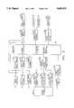
- FIG. 3is a more detailed block diagram showing the components comprising the laser-directed ranging system depicted in FIG. 2 and their interrelationship;
- FIG. 4depicts successive images from the stereo cameras shown in FIG. 2 to illustrate the frame subtraction technique of the present invention
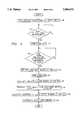
- FIG. 5is a flow chart describing the ranging algorithm executed by the computer shown in FIG. 2;
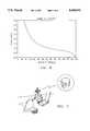
- FIG. 6is a typical graph of the relationship between the stereometric image disparity and the range for the ranging system depicted in FIG. 2;
- FIG. 7is a perspective drawing illustrating a robotics application for the ranging system of the present invention.
- FIG. 8is a perspective drawing illustrating an application for the present invention involving robotics assistance to handicapped individuals.
- a laser-directed ranging system 10constructed in accordance with the principles of the present invention includes a stereo camera imaging and ranging system 12, a head-mounted display system 14, a position and orientation sensor system 16, a laser/camera platform control system 18, and a robot control system 20.
- the ranging system 10is designed to permit an operator to control a robot 19 at a remote location with head motions and voice commands.
- the stereo camera imaging and ranging system 12which is located at a location remote to the operator, captures visual images of the remote location.
- the visual imagesare conveyed electronically to the operator and provide real time feedback to the operator's head-mounted display system 14, whereby the operator can observe and direct the robot.
- a laser 42 or other direction light sourcepreferably mounts between the two cameras 30 in the stereo camera imaging and ranging system 12.
- the laser 42aligns in a parallel plane with the video cameras 30.
- the laser 42may be offset with respect to the video cameras, so long as the laser spot hits and is reflected off the target.
- the laser 42enables the operator to illuminate a target.
- the video images, both laser-illuminated and not,are captured from the stereo cameras 30 in conventional frame grabber circuitry 34 and are used in a computer-based ranging algorithm to identify the position of a target relative to the position of the robot 19.
- the position and orientation sensor system 16connects to the operator's helmet and monitors the position and orientation of the operator's head.
- the position and orientation datais delivered to the laser/camera platform control system 18, which adjusts the position and orientation of the laser and cameras in conformance with the operator's head movements.
- the operatorturns on the laser 42 by voice command and points the laser at the robot target by appropriate head movements.
- the operatorcommands the system to identify the range to the target and commands the robot to engage the target as desired.
- the components preferably comprising the ranging system 10are identified and their interrelationship and operation are explained in detail.
- the stereo camera imaging and ranging system 12comprises left and right video cameras 30, 32, each connected through conventional video frame grabber boards 34, 36 to a general purpose computer 40, such as a personal computer or workstation, and a laser pointer 42 connected to the computer 40 through a current relay switch 44.
- a general purpose computer 40such as a personal computer or workstation
- a laser pointer 42connected to the computer 40 through a current relay switch 44.
- the video cameras 30, 32preferably are high quality color video cameras having an image discrimination capability sufficient for the desired application of the ranging system, preferably with automatic gain control.
- One suitable camera typeis the Model TMC-50 manufactured by Pulnix.
- the video cameras 30, 32are mounted with their lines of sight preferably in parallel alignment on a platform, which is described more particularly below in the section entitled, "Laser/Camera Platform Control System.”
- the left and right camera, 30, 32are connected to the conventional video frame grabber boards 34, 36, which are received in slots in the chassis of the computer 40.
- the frame grabber boardscapture a video image on command, digitize the image, and store the digitized image or transmit it on command to the computer 40.
- the computer 40may be any microprocessor-based computer capable of executing the control and analysis algorithms described herein, including, for example, Model No. Sparc 2 workstation manufactured by Sun Microsystems, Inc.
- the laser 42preferably is a low power laser, such as a 1 mW, class II ruby laser diode, which is relatively inexpensive and safe for human operating environments.
- a ranging algorithmas described below, is executed by the computer 40 and sets and resets a digital I/O bit to activate and deactivate the conventional current relay switch 44, which energizes and deenergizes the laser 42, all as is well known to persons having ordinary skill in the art of designing and implementing real time computer control systems.
- Applicantshave devised a novel ranging algorithm that combines the use of a laser with conventional stereometric ranging theory to provide a ranging system that does not require processing of large numbers of convolution and cross-correlation algorithms.
- Applicant's ranging algorithmcan be used in real-time telerobotics applications without a computer having enhanced processing capabilities.
- Frame A and Frame Bshow representative images from the left and right cameras, respectively.
- Frames C and Drepresent images of the same scene from the two cameras, with the target box illuminated by the laser 42.
- Frames A and Care digitized and stored by the frame grabber board 34 for the left camera 30, as Frames B and D are digitized and stored by the frame grabber board 36 for the right camera 32.
- the computer 40compares Frame A with Frame C and creates a third image in which the common pixels from both frames are eliminated, leaving only the spot created by the laser illumination. In effect, the image of Frame A is subtracted from the image of Frame C. The same process is applied to Frames B and D to create an image of the laser spot from the right camera. The horizontal disparity between the spots in the two images can then be calculated, and the range to the target box can be calculated by conventional stereometric ranging analysis.
- the processbegins by activating the laser in step 50.
- Thiscan be initiated by a conventional manual switch connected to the computer or by the operator's oral command, which is translated through a voice recognition system forming a part of the computer.
- Other techniques for activating the laseralso can be used without departing from the principles of the present invention.
- step 52the algorithm waits for an indication from the operator that the operator is ready to take a range measurement.
- the algorithmturns off the laser (step 54) and then determines whether the camera is stable enough to execute the ranging measurement (step 56). This is accomplished, for example, by executing successive frame subtractions until the resulting difference for both cameras is a blank image for a predetermined length of time.
- each of the two frame grabber boardscapture an image of the target (step 58)
- the laseris turned on (step 60)
- each of the two frame grabber boardscapture an image of the target as illuminated by the laser (step 62)
- the computersubtracts the non-illuminated image from the corresponding illuminated image to create a pair of images of the laser spot (step 64).
- step 66the horizontal and vertical coordinates of the centroid of the laser spot in each of the two images can be calculated from the following formulas: ##EQU2## where, N represents the number of pixels comprising the laser spot after frame subtraction, and (x n , y n ) are the coordinates of these pixels in the image. If the video cameras are positioned in a common vertical plane, there will be no disparity in the vertical plane, so that only horizontal disparity need be determined. If the cameras are not in a common vertical plane, then vertical disparity also must be determined.
- the horizontal disparity and the range to the targetare calculated in step 68.
- the horizontal disparity, dwhich preferably is measured in pixels, is calculated as follows:
- x lis the horizontal coordinate of the centroid of the laser spot as viewed through the left camera
- x ris the horizontal coordinate of the centroid of the laser spot as viewed through the right camera
- the normal range, z, to the targetthen can be calculated as follows: ##EQU3## where f is the focal length of the two cameras, and b is the baseline separation between the lines of sight of the parallel cameras.
- the range measurementmay be calibrated empirically by determining the disparity, as described above, for a plurality of known ranges.
- the robotic armcan be used to move the target along the camera centerline for calibration through the implementation of a kinematics algorithm, which moves the robotic arm in Cartesian space in a "linear fashion".
- a Kinematics algorithmtypically is provided with a commercial robotics system such as the type PUMA 560 robotics manipulator manufactured by Staubli.
- FIG. 6depicts a typical curve for an empirical measurement of the range versus disparity curve. If range is to be determined from an empirical calibration of the cameras, step 68 of the ranging algorithm (FIG. 5) becomes, instead of a calculation as indicated above, a table look-up of range from measured disparity, or a calculation of range from disparity using the function that fits the empirically measured curve.
- the head-mounted display system 14provides the operator with video feedback of the environment at the remote location.
- the stereo video signals generated by the stereo cameras 30, 32are channeled to the computer 40, which executes a graphics algorithm to generate an artificial video image.
- the video imagethen is transmitted by the computer 40 to a display driver 80, which activates a helmet-like device 82 with two display screens, each fed from one of the video channels, that depict the remote scene to the operator.
- the video image from the stereo camerasmay be transmitted to the head-mounted display without use of a graphics generated image.
- the necessary software and equipmentmay be purchased commercially.
- One such suitable display systemis the Flight Helmet manufactured by Virtual Research.
- the preferred embodiment of the present inventionalso includes a microphone 84, which is physically attached to the helmet 82 and coupled through a voice recognition system 86 to the computer 40.
- the microphone and voice recognition systemenable the operator to execute control operations (turn on laser, find range to target, move robot to target, etc.) without using hands or feet. This feature is particularly critical in an application of the invention for the benefit of an operator who is required to use his hands for other tasks, or for the benefit of handicapped persons, as described more particularly below.
- a commercially available voice recognition system suitable for the present applicationis the DS400 manufactured by Speech Systems, Inc.
- the voice command systemis operable for generating digital data messages within the computer that are sent to servo-mechanisms which position the robotic arm as instructed, in accordance with techniques known in the art.
- the position and orientation sensor system 16detects the position and orientation of the operator's head and communicates the information to the computer, as will be described in greater detail, which in turn communicates the information to the laser/camera platform control system 18. In this manner, the position and orientation sensor system 16 enables the stereo cameras and attached laser at a remote location to mimic movements of the operator's head.
- the position and orientation sensor systemincludes a source 90, for generating a position sensor and orientation magnetic field in the region of the head-mounted display helmet 82 and a position and orientation sensor 92 mounted on the helmet 82 for generating electrical signals representative of position and orientation of the helmet within the magnetic field generated by the source 90.
- a Polhemus "Fast Trak” sensoris used as the position and orientation sensor 92.
- the systemfurther includes an interface unit 94 that receives electrical signals from the sensor 92 and generates digital position data (x, y, z) and digital orientation data (roll, pitch, yaw) that is communicated to the computer 40.
- the position and orientation sensor system described hereinis available commercially. Products suitable for use in this application include the FastTrack systems manufactured by Polhemus or The Bird manufactured by Ascension Device.
- the laser/camera platform control system 18is a positioning apparatus for moving the stereo cameras and the laser relative in response to motion of the operator's head at a remote location.
- the laser/camera platform control system 18comprises a mechanical platform support structure 100, a roll-axis servo motor 102, a pitch-axis servo motor 104, a yaw-axis servo motor 106, and a motor controller 108.
- the stereo cameras 30, 32are affixed to the platform 100 in such a manner that the lines of sight of the two cameras are parallel.
- the laser diode 42is also affixed to the platform 100 and aligned such that its beam projects along a line that is parallel to the lines of sight of the stereo cameras 30, 32.
- the beam of the laser diode 42need not lie along a line that is co-planar with the lines of sight of the stereo cameras 30, 32.
- the platform 100has three degrees-of-freedom motion capability, with each degree-of-freedom driven by one of the three servo motors 102, 104, 106.
- the three motors 102, 104, 106are controlled by the motor controller 108, which receives orientation position commands from the computer 40.
- the computer 4Dreceives data reflecting the position (x, y, z) and orientation (roll, pitch, yaw) of the operator's head, as described above in the section entitled, "Position and Orientation Sensor System,” and transforms the orientation data into a set of orientation angles (roll, pitch, yaw) that are communicated to the motor controller 108.
- the servo motors 102, 104, 106preferably comprise DC-servo motors, such as the type 2842-024C motor manufactured by MicroMo.
- the motor controllermay be, for example, a type LM629 controller manufactured by National Semiconductor, Inc.
- the robot 19(FIG. 2), comprises the output device for the telerobotic application of the present invention, and the robot arm selected for use in connection with the present invention may vary from one application to the next.
- the robot control systemtypically includes a robot arm 110, comprising one or more sections, and a robot motion controller 112, and a kinematics algorithm executed by the computer 40.
- the robot arm 110preferably includes an end effector, such as a mechanical hand 111 for accomplishing the purposes of the robot arm.
- an end effectorsuch as a mechanical hand 111 for accomplishing the purposes of the robot arm.
- One goal of the present inventionis to enable the system 10 to command the end effector on the robot arm 110 to a precise position that corresponds to the position of the target object.
- the computer 40defines the Cartesian coordinates of a position command based on information ascertained through the ranging algorithm, as described above. Using the kinematics algorithm, the computer 40 computes the motion controller commands needed to move the end effector on the robot arm 110 to the target position. The commands are communicated by the computer 40 to the motion controller 112, which in turn controls the motors that move the robot arm 110.
- One robot arm suitable for telerobotics applicationsis the type PUMA 560 manipulator manufactured by Staubli.
- a typical operating procedureinvolves the operator wearing the head-mounted display 82, with the orientation sensor 92 attached above the helmet, and the microphone 84 positioned near the mouth.
- the sensor system source 90preferably is mounted on a fixture attached to the floor.
- the sensor 92 on the helmetwill measure the orientation of the operator's head relative to the source's reference frame to define a position for the sensor 92 in three dimensional space.
- the operatorcan change the position of the sensor 92 by turning or changing the elevation of his or her head. This head movement, therefore, is analogous to the manipulation of a joystick.
- the orientation sensor systemoutputs data to the computer 40, preferably via a RS232 serial link.
- the operator's head orientationis then transformed through the kinematics algorithm of the stereo camera platform 108 to obtain joint commands that will move the laser/camera platform 100 to the same orientation relative to the robot's own reference frame, in accordance with conventional techniques.
- the joint commandsare sent to the laser/camera platform motor controller 108 via a parallel or RS232 port.
- the operatorcan simply point the laser 42 at the target.
- the reflected laser “dot”can be “seen” by both the frame grabbers 34, 36 as well as the operator.
- the frame grabbers 34, 36capture the video images and digitize them.
- the digital imagesare stored in memory and transmitted to the computer 40 for processing.
- the laser "dot”is isolated in each of the left and right images.
- the computer 40finds the centroid of the laser "dot” in the left and right images according to the method of FIG. 5, as discussed above.
- the computer 40preferably uses the x-axis disparity between the two centroids to calculate the range of the target using the ranging algorithm.
- the target's Cartesian position relative to the laser/camera platform 100can be determined. Once the Cartesian position of the target is known, the robot arm 110 can be commanded to move to that location by voice command via the microphone 84. Once the operator has completed the manipulation of the target object, the laser range finding system can be deactivated by voice command.
- a robot arm 120can be mounted on a support structure adjacent a workpiece.
- the support structurecomprises a wheelchair 122, and the operator can use the alternative embodiment of the invention to identify the target location so that the robot can grasp or manipulate the target object based on the voice commands given by the user.
- the stereoscopic cameras 124 and laser 126are mounted on a helmet 128 worn by the operator along with the magnetic direction/position sensors 130.
- This embodimenteliminates the need for a laser/camera platform control system because the camera and laser will be moved into position locally by the operator's head movements instead of remotely.
- the present inventionallows the operator to specify the target of interest virtually hands-free.
- the hands-free method of target selectionis more user-friendly to physically handicapped persons than those methods that require some form of manual pointing.
- computationis limited by using the frame subtraction algorithm with the laser illuminated image and the non-laser illuminated image. This reduces the memory/computer size and power necessary to perform the computation, as well as allowing the algorithm to run faster than others on a given processor.
Landscapes
- Engineering & Computer Science (AREA)
- Physics & Mathematics (AREA)
- General Physics & Mathematics (AREA)
- Remote Sensing (AREA)
- Radar, Positioning & Navigation (AREA)
- Electromagnetism (AREA)
- Computer Networks & Wireless Communication (AREA)
- Multimedia (AREA)
- Computer Vision & Pattern Recognition (AREA)
- Theoretical Computer Science (AREA)
- Signal Processing (AREA)
- Optics & Photonics (AREA)
- Length Measuring Devices By Optical Means (AREA)
- Manipulator (AREA)
Abstract
Description
d=x.sub.l -x.sub.r
Claims (37)
Priority Applications (1)
| Application Number | Priority Date | Filing Date | Title |
|---|---|---|---|
| US08/425,002US5684531A (en) | 1995-04-10 | 1995-04-10 | Ranging apparatus and method implementing stereo vision system |
Applications Claiming Priority (1)
| Application Number | Priority Date | Filing Date | Title |
|---|---|---|---|
| US08/425,002US5684531A (en) | 1995-04-10 | 1995-04-10 | Ranging apparatus and method implementing stereo vision system |
Publications (1)
| Publication Number | Publication Date |
|---|---|
| US5684531Atrue US5684531A (en) | 1997-11-04 |
Family
ID=23684740
Family Applications (1)
| Application Number | Title | Priority Date | Filing Date |
|---|---|---|---|
| US08/425,002Expired - Fee RelatedUS5684531A (en) | 1995-04-10 | 1995-04-10 | Ranging apparatus and method implementing stereo vision system |
Country Status (1)
| Country | Link |
|---|---|
| US (1) | US5684531A (en) |
Cited By (55)
| Publication number | Priority date | Publication date | Assignee | Title |
|---|---|---|---|---|
| US6052083A (en)* | 1998-03-12 | 2000-04-18 | Trimble Navigation Limited | Method and apparatus for position identification |
| US6072523A (en)* | 1995-09-27 | 2000-06-06 | Yeda Research And Development Co. Ltd. | System and a method of three-dimensional imaging |
| US6148100A (en)* | 1996-12-20 | 2000-11-14 | Bechtel Bwxt Idaho, Llc | 3-dimensional telepresence system for a robotic environment |
| FR2799002A1 (en)* | 1999-09-28 | 2001-03-30 | Thomson Csf | ACTIVE LASER IMAGING PROCESS |
| US6278479B1 (en)* | 1998-02-24 | 2001-08-21 | Wilson, Hewitt & Associates, Inc. | Dual reality system |
| WO2003005057A1 (en)* | 2001-07-06 | 2003-01-16 | Leica Geosystems Ag | Method and device for suppressing electromagnetic background radiation in an image |
| GB2394852A (en)* | 2002-10-31 | 2004-05-05 | Hewlett Packard Co | Image capture systems using motion detection |
| US20040179714A1 (en)* | 2003-03-11 | 2004-09-16 | Jouppi Norman Paul | Telepresence system with simultaneous automatic preservation of user height, perspective, and vertical gaze |
| US20040233290A1 (en)* | 2003-03-26 | 2004-11-25 | Takeshi Ohashi | Diagnosing device for stereo camera mounted on robot, and diagnostic method of stereo camera mounted on robot apparatus |
| US20050200325A1 (en)* | 2004-03-12 | 2005-09-15 | Samsung Electronics Co., Ltd. | Remote robot control method using three-dimensional pointing procedure and robot control system using the remote robot control method |
| US6958746B1 (en)* | 1999-04-05 | 2005-10-25 | Bechtel Bwxt Idaho, Llc | Systems and methods for improved telepresence |
| US20060008136A1 (en)* | 2004-07-06 | 2006-01-12 | Christophe Leroux | Process for gripping an object by means of a Robot arm equipped with a camera |
| US20060112034A1 (en)* | 2003-06-02 | 2006-05-25 | Matsushita Electric Industrial Co., Ltd. | Article handling system and method and article management system and method |
| US7190392B1 (en)* | 1997-10-23 | 2007-03-13 | Maguire Jr Francis J | Telepresence system and active/passive mode display for use therein |
| US20070185617A1 (en)* | 2006-02-07 | 2007-08-09 | Samsung Electronics Co., Ltd. | Autonomous mobile robot and method of controlling the same |
| US20080009964A1 (en)* | 2006-07-05 | 2008-01-10 | Battelle Energy Alliance, Llc | Robotics Virtual Rail System and Method |
| US20080009969A1 (en)* | 2006-07-05 | 2008-01-10 | Battelle Energy Alliance, Llc | Multi-Robot Control Interface |
| US20080009968A1 (en)* | 2006-07-05 | 2008-01-10 | Battelle Energy Alliance, Llc | Generic robot architecture |
| EP1933167A3 (en)* | 2006-12-15 | 2009-01-14 | Sick Ag | Optoelectronic sensor and method for detecting and determining the distance of an object |
| US20090040299A1 (en)* | 2006-05-02 | 2009-02-12 | Telesis Technologies, Inc. | Laser safety system with beam steering |
| US20090091583A1 (en)* | 2007-10-06 | 2009-04-09 | Mccoy Anthony | Apparatus and method for on-field virtual reality simulation of US football and other sports |
| US20090234499A1 (en)* | 2008-03-13 | 2009-09-17 | Battelle Energy Alliance, Llc | System and method for seamless task-directed autonomy for robots |
| US20110054689A1 (en)* | 2009-09-03 | 2011-03-03 | Battelle Energy Alliance, Llc | Robots, systems, and methods for hazard evaluation and visualization |
| US20110063417A1 (en)* | 2009-07-17 | 2011-03-17 | Peters Ii Richard Alan | System and method for automatic calibration of stereo images |
| US20110077800A1 (en)* | 2008-08-18 | 2011-03-31 | Raytheon Company | Systems and methods for triaging a plurality of targets with a robotic vehicle |
| US20110190930A1 (en)* | 2010-02-04 | 2011-08-04 | Intouch Technologies, Inc. | Robot user interface for telepresence robot system |
| US8060389B2 (en) | 2000-06-07 | 2011-11-15 | Apple Inc. | System and method for anonymous location based services |
| CN102636788A (en)* | 2012-05-03 | 2012-08-15 | 山东卡尔电气股份有限公司 | Ranging method and system for tracking laser point |
| US8538685B2 (en) | 2000-06-07 | 2013-09-17 | Apple Inc. | System and method for internet connected service providing heterogeneous mobile systems with situational location relevant content |
| US8965578B2 (en) | 2006-07-05 | 2015-02-24 | Battelle Energy Alliance, Llc | Real time explosive hazard information sensing, processing, and communication for autonomous operation |
| USRE45525E1 (en)* | 2007-08-27 | 2015-05-19 | Soarealm, Inc. | Apparatus and method of simulating a somatosensory experience in space |
| US20160124506A1 (en)* | 2014-11-03 | 2016-05-05 | Samsung Electronics Co., Ltd. | Electronic device and method for controlling external object |
| CN106165415A (en)* | 2014-04-07 | 2016-11-23 | 诺基亚技术有限公司 | Stereos copic viewing |
| CN106352799A (en)* | 2016-08-10 | 2017-01-25 | 国网浙江省电力公司金华供电公司 | Measuring instrument for power transmission line tower |
| US20170212723A1 (en)* | 2011-08-21 | 2017-07-27 | M.S.T. Medical Surgery Technologies Ltd | Vocally activated surgical control system |
| CN108225281A (en)* | 2017-12-25 | 2018-06-29 | 中国航空工业集团公司洛阳电光设备研究所 | A kind of pilot's head pose detection method based on video camera |
| US20190012789A1 (en)* | 2015-07-21 | 2019-01-10 | Heptagon Micro Optics Pte. Ltd. | Generating a disparity map based on stereo images of a scene |
| US10399223B2 (en) | 2011-01-28 | 2019-09-03 | Intouch Technologies, Inc. | Interfacing with a mobile telepresence robot |
| WO2020050179A1 (en)* | 2018-09-03 | 2020-03-12 | 川崎重工業株式会社 | Robot system |
| US10818097B2 (en) | 2017-12-12 | 2020-10-27 | Disney Enterprises, Inc. | Spatial position calculation system for objects in virtual reality or augmented reality environment |
| US20210141597A1 (en)* | 2011-08-21 | 2021-05-13 | Transenterix Europe S.A.R.L. | Vocally actuated surgical control system |
| US11020858B2 (en)* | 2018-08-23 | 2021-06-01 | Toyota Researching Institute, Inc. | Lifting robot systems |
| CN114578336A (en)* | 2022-03-30 | 2022-06-03 | 江南工业集团有限公司 | Self-identification binocular range finder |
| JPWO2022124398A1 (en)* | 2020-12-10 | 2022-06-16 | ||
| US11373341B2 (en)* | 2019-04-03 | 2022-06-28 | Hochschule Offenburg | Method for controlling a device, in particular, a prosthetic hand or a robotic arm |
| JPWO2022149497A1 (en)* | 2021-01-05 | 2022-07-14 | ||
| US11389064B2 (en) | 2018-04-27 | 2022-07-19 | Teladoc Health, Inc. | Telehealth cart that supports a removable tablet with seamless audio/video switching |
| US11636944B2 (en) | 2017-08-25 | 2023-04-25 | Teladoc Health, Inc. | Connectivity infrastructure for a telehealth platform |
| US11742094B2 (en) | 2017-07-25 | 2023-08-29 | Teladoc Health, Inc. | Modular telehealth cart with thermal imaging and touch screen user interface |
| US11787060B2 (en) | 2008-03-20 | 2023-10-17 | Teladoc Health, Inc. | Remote presence system mounted to operating room hardware |
| US11798683B2 (en) | 2010-03-04 | 2023-10-24 | Teladoc Health, Inc. | Remote presence system including a cart that supports a robot face and an overhead camera |
| US11862302B2 (en) | 2017-04-24 | 2024-01-02 | Teladoc Health, Inc. | Automated transcription and documentation of tele-health encounters |
| WO2024013895A1 (en)* | 2022-07-13 | 2024-01-18 | 日本電信電話株式会社 | Remote control system, remote control method, and remote control program |
| US12224059B2 (en) | 2011-02-16 | 2025-02-11 | Teladoc Health, Inc. | Systems and methods for network-based counseling |
| WO2025062952A1 (en)* | 2023-09-22 | 2025-03-27 | ソニーグループ株式会社 | Information processing device, information processing method, and computer-readable recording medium |
Citations (15)
| Publication number | Priority date | Publication date | Assignee | Title |
|---|---|---|---|---|
| US4969735A (en)* | 1989-03-07 | 1990-11-13 | Sperry Marine Inc. | Passive range finding apparatus utilizing television sensors |
| US4979815A (en)* | 1989-02-17 | 1990-12-25 | Tsikos Constantine J | Laser range imaging system based on projective geometry |
| US5040116A (en)* | 1988-09-06 | 1991-08-13 | Transitions Research Corporation | Visual navigation and obstacle avoidance structured light system |
| US5109345A (en)* | 1990-02-20 | 1992-04-28 | The United States Of America As Represented By The Administrator Of The National Aeronautics And Space Administration | Closed-loop autonomous docking system |
| US5109425A (en)* | 1988-09-30 | 1992-04-28 | The United States Of America As Represented By The United States National Aeronautics And Space Administration | Method and apparatus for predicting the direction of movement in machine vision |
| US5130794A (en)* | 1990-03-29 | 1992-07-14 | Ritchey Kurtis J | Panoramic display system |
| US5168141A (en)* | 1991-06-14 | 1992-12-01 | General Electric Company | Vision guided laser welding |
| US5175616A (en)* | 1989-08-04 | 1992-12-29 | Her Majesty The Queen In Right Of Canada, As Represented By The Minister Of National Defence Of Canada | Stereoscopic video-graphic coordinate specification system |
| US5216476A (en)* | 1991-10-15 | 1993-06-01 | Synectics Corporation | Photogrammetric laser system |
| US5320538A (en)* | 1992-09-23 | 1994-06-14 | Hughes Training, Inc. | Interactive aircraft training system and method |
| US5331413A (en)* | 1992-09-28 | 1994-07-19 | The United States Of America As Represented By The United States National Aeronautics And Space Administration | Adjustable control station with movable monitors and cameras for viewing systems in robotics and teleoperations |
| US5420828A (en)* | 1992-06-25 | 1995-05-30 | Geiger; Michael B. | Viewing screen assembly |
| US5495576A (en)* | 1993-01-11 | 1996-02-27 | Ritchey; Kurtis J. | Panoramic image based virtual reality/telepresence audio-visual system and method |
| US5510625A (en)* | 1979-04-30 | 1996-04-23 | Sensor Adaptive Machines Inc. | Method and apparatus for electro optically determining the dimension, location and attitude of objects |
| US5526022A (en)* | 1993-01-06 | 1996-06-11 | Virtual I/O, Inc. | Sourceless orientation sensor |
- 1995
- 1995-04-10USUS08/425,002patent/US5684531A/ennot_activeExpired - Fee Related
Patent Citations (15)
| Publication number | Priority date | Publication date | Assignee | Title |
|---|---|---|---|---|
| US5510625A (en)* | 1979-04-30 | 1996-04-23 | Sensor Adaptive Machines Inc. | Method and apparatus for electro optically determining the dimension, location and attitude of objects |
| US5040116A (en)* | 1988-09-06 | 1991-08-13 | Transitions Research Corporation | Visual navigation and obstacle avoidance structured light system |
| US5109425A (en)* | 1988-09-30 | 1992-04-28 | The United States Of America As Represented By The United States National Aeronautics And Space Administration | Method and apparatus for predicting the direction of movement in machine vision |
| US4979815A (en)* | 1989-02-17 | 1990-12-25 | Tsikos Constantine J | Laser range imaging system based on projective geometry |
| US4969735A (en)* | 1989-03-07 | 1990-11-13 | Sperry Marine Inc. | Passive range finding apparatus utilizing television sensors |
| US5175616A (en)* | 1989-08-04 | 1992-12-29 | Her Majesty The Queen In Right Of Canada, As Represented By The Minister Of National Defence Of Canada | Stereoscopic video-graphic coordinate specification system |
| US5109345A (en)* | 1990-02-20 | 1992-04-28 | The United States Of America As Represented By The Administrator Of The National Aeronautics And Space Administration | Closed-loop autonomous docking system |
| US5130794A (en)* | 1990-03-29 | 1992-07-14 | Ritchey Kurtis J | Panoramic display system |
| US5168141A (en)* | 1991-06-14 | 1992-12-01 | General Electric Company | Vision guided laser welding |
| US5216476A (en)* | 1991-10-15 | 1993-06-01 | Synectics Corporation | Photogrammetric laser system |
| US5420828A (en)* | 1992-06-25 | 1995-05-30 | Geiger; Michael B. | Viewing screen assembly |
| US5320538A (en)* | 1992-09-23 | 1994-06-14 | Hughes Training, Inc. | Interactive aircraft training system and method |
| US5331413A (en)* | 1992-09-28 | 1994-07-19 | The United States Of America As Represented By The United States National Aeronautics And Space Administration | Adjustable control station with movable monitors and cameras for viewing systems in robotics and teleoperations |
| US5526022A (en)* | 1993-01-06 | 1996-06-11 | Virtual I/O, Inc. | Sourceless orientation sensor |
| US5495576A (en)* | 1993-01-11 | 1996-02-27 | Ritchey; Kurtis J. | Panoramic image based virtual reality/telepresence audio-visual system and method |
Cited By (103)
| Publication number | Priority date | Publication date | Assignee | Title |
|---|---|---|---|---|
| US6072523A (en)* | 1995-09-27 | 2000-06-06 | Yeda Research And Development Co. Ltd. | System and a method of three-dimensional imaging |
| US6148100A (en)* | 1996-12-20 | 2000-11-14 | Bechtel Bwxt Idaho, Llc | 3-dimensional telepresence system for a robotic environment |
| US7190392B1 (en)* | 1997-10-23 | 2007-03-13 | Maguire Jr Francis J | Telepresence system and active/passive mode display for use therein |
| US7587747B2 (en) | 1997-10-23 | 2009-09-08 | Maguire Jr Francis J | Telepresence method and apparatus for simultaneous use by multiple active/passive users |
| US6278479B1 (en)* | 1998-02-24 | 2001-08-21 | Wilson, Hewitt & Associates, Inc. | Dual reality system |
| US6498618B2 (en)* | 1998-02-24 | 2002-12-24 | Phillip C. Wilson | Dual reality system |
| US6052083A (en)* | 1998-03-12 | 2000-04-18 | Trimble Navigation Limited | Method and apparatus for position identification |
| US6958746B1 (en)* | 1999-04-05 | 2005-10-25 | Bechtel Bwxt Idaho, Llc | Systems and methods for improved telepresence |
| FR2799002A1 (en)* | 1999-09-28 | 2001-03-30 | Thomson Csf | ACTIVE LASER IMAGING PROCESS |
| EP1089090A1 (en)* | 1999-09-28 | 2001-04-04 | Thomson-Csf | Method of active imaging using a laser |
| US8060389B2 (en) | 2000-06-07 | 2011-11-15 | Apple Inc. | System and method for anonymous location based services |
| US8538685B2 (en) | 2000-06-07 | 2013-09-17 | Apple Inc. | System and method for internet connected service providing heterogeneous mobile systems with situational location relevant content |
| US20040208340A1 (en)* | 2001-07-06 | 2004-10-21 | Holger Kirschner | Method and device for suppressing electromagnetic background radiation in an image |
| US7809182B2 (en)* | 2001-07-06 | 2010-10-05 | Leica Geosystems Ag | Method and device for suppressing electromagnetic background radiation in an image |
| AU2002319202B8 (en)* | 2001-07-06 | 2003-01-21 | Leica Geosystems Ag | Method and device for suppressing electromagnetic background radiation in an image |
| WO2003005057A1 (en)* | 2001-07-06 | 2003-01-16 | Leica Geosystems Ag | Method and device for suppressing electromagnetic background radiation in an image |
| CN1332221C (en)* | 2001-07-06 | 2007-08-15 | 莱卡地球系统公开股份有限公司 | Method and device for suppressing electromagnetic background radiation in image |
| AU2002319202B2 (en)* | 2001-07-06 | 2007-05-24 | Leica Geosystems Ag | Method and device for suppressing electromagnetic background radiation in an image |
| GB2394852B (en)* | 2002-10-31 | 2006-12-20 | Hewlett Packard Co | Image capture systems using motion detection |
| GB2394852A (en)* | 2002-10-31 | 2004-05-05 | Hewlett Packard Co | Image capture systems using motion detection |
| US7209803B2 (en)* | 2003-02-17 | 2007-04-24 | Matsushita Electric Industrial Co., Ltd. | Article handling system and method and article management system and method |
| US7187998B2 (en)* | 2003-02-17 | 2007-03-06 | Matsushita Electric Industrial Co., Ltd. | Article handling system and method and article management system and method |
| US20060111811A1 (en)* | 2003-02-17 | 2006-05-25 | Matsushita Electric Industrial Co., Ltd. | Article handling system and method and article management system and method |
| US20060111812A1 (en)* | 2003-02-17 | 2006-05-25 | Matsushita Electric Industrial Co., Ltd. | Article handling system and method and article management system and method |
| US7593546B2 (en)* | 2003-03-11 | 2009-09-22 | Hewlett-Packard Development Company, L.P. | Telepresence system with simultaneous automatic preservation of user height, perspective, and vertical gaze |
| US20040179714A1 (en)* | 2003-03-11 | 2004-09-16 | Jouppi Norman Paul | Telepresence system with simultaneous automatic preservation of user height, perspective, and vertical gaze |
| US20040233290A1 (en)* | 2003-03-26 | 2004-11-25 | Takeshi Ohashi | Diagnosing device for stereo camera mounted on robot, and diagnostic method of stereo camera mounted on robot apparatus |
| US7373270B2 (en)* | 2003-03-26 | 2008-05-13 | Sony Corporation | Diagnosing device for stereo camera mounted on robot, and diagnostic method of stereo camera mounted on robot apparatus |
| US7191035B2 (en)* | 2003-06-02 | 2007-03-13 | Matsushita Electric Industrial Co., Ltd. | Article handling system and method and article management system and method |
| US20060112034A1 (en)* | 2003-06-02 | 2006-05-25 | Matsushita Electric Industrial Co., Ltd. | Article handling system and method and article management system and method |
| US20060116973A1 (en)* | 2003-06-02 | 2006-06-01 | Matsushita Electric Industrial Co., Ltd. | Article handling system and method and article management system and method |
| US7206668B2 (en)* | 2003-06-02 | 2007-04-17 | Matsushita Electric Industrial Co., Ltd. | Article handling system and method and article management system and method |
| US7187999B2 (en)* | 2003-06-02 | 2007-03-06 | Matsushita Electric Industrial Co., Ltd. | Article handling system and method and article management system and method |
| US20050200325A1 (en)* | 2004-03-12 | 2005-09-15 | Samsung Electronics Co., Ltd. | Remote robot control method using three-dimensional pointing procedure and robot control system using the remote robot control method |
| US7526362B2 (en)* | 2004-03-12 | 2009-04-28 | Samsung Electronics Co., Ltd. | Remote robot control method using three-dimensional pointing procedure and robot control system using the remote robot control method |
| US20060008136A1 (en)* | 2004-07-06 | 2006-01-12 | Christophe Leroux | Process for gripping an object by means of a Robot arm equipped with a camera |
| US7583835B2 (en)* | 2004-07-06 | 2009-09-01 | Commissariat A L'energie Atomique | Process for gripping an object by means of a robot arm equipped with a camera |
| US20070185617A1 (en)* | 2006-02-07 | 2007-08-09 | Samsung Electronics Co., Ltd. | Autonomous mobile robot and method of controlling the same |
| US8280099B2 (en)* | 2006-05-02 | 2012-10-02 | Telesis Technologies, Inc. | Laser safety system with beam steering |
| US20090040299A1 (en)* | 2006-05-02 | 2009-02-12 | Telesis Technologies, Inc. | Laser safety system with beam steering |
| US8073564B2 (en)* | 2006-07-05 | 2011-12-06 | Battelle Energy Alliance, Llc | Multi-robot control interface |
| US20080009968A1 (en)* | 2006-07-05 | 2008-01-10 | Battelle Energy Alliance, Llc | Generic robot architecture |
| US7801644B2 (en) | 2006-07-05 | 2010-09-21 | Battelle Energy Alliance, Llc | Generic robot architecture |
| US9213934B1 (en) | 2006-07-05 | 2015-12-15 | Battelle Energy Alliance, Llc | Real time explosive hazard information sensing, processing, and communication for autonomous operation |
| US8965578B2 (en) | 2006-07-05 | 2015-02-24 | Battelle Energy Alliance, Llc | Real time explosive hazard information sensing, processing, and communication for autonomous operation |
| US20080009964A1 (en)* | 2006-07-05 | 2008-01-10 | Battelle Energy Alliance, Llc | Robotics Virtual Rail System and Method |
| US20080009969A1 (en)* | 2006-07-05 | 2008-01-10 | Battelle Energy Alliance, Llc | Multi-Robot Control Interface |
| US7974738B2 (en) | 2006-07-05 | 2011-07-05 | Battelle Energy Alliance, Llc | Robotics virtual rail system and method |
| EP1933167A3 (en)* | 2006-12-15 | 2009-01-14 | Sick Ag | Optoelectronic sensor and method for detecting and determining the distance of an object |
| USRE45525E1 (en)* | 2007-08-27 | 2015-05-19 | Soarealm, Inc. | Apparatus and method of simulating a somatosensory experience in space |
| US8368721B2 (en)* | 2007-10-06 | 2013-02-05 | Mccoy Anthony | Apparatus and method for on-field virtual reality simulation of US football and other sports |
| US20090091583A1 (en)* | 2007-10-06 | 2009-04-09 | Mccoy Anthony | Apparatus and method for on-field virtual reality simulation of US football and other sports |
| US8271132B2 (en) | 2008-03-13 | 2012-09-18 | Battelle Energy Alliance, Llc | System and method for seamless task-directed autonomy for robots |
| US20090234499A1 (en)* | 2008-03-13 | 2009-09-17 | Battelle Energy Alliance, Llc | System and method for seamless task-directed autonomy for robots |
| US11787060B2 (en) | 2008-03-20 | 2023-10-17 | Teladoc Health, Inc. | Remote presence system mounted to operating room hardware |
| US20110077800A1 (en)* | 2008-08-18 | 2011-03-31 | Raytheon Company | Systems and methods for triaging a plurality of targets with a robotic vehicle |
| US8682522B2 (en)* | 2008-08-18 | 2014-03-25 | Raytheon Company | Systems and methods for triaging a plurality of targets with a robotic vehicle |
| US8717421B2 (en)* | 2009-07-17 | 2014-05-06 | II Richard Alan Peters | System and method for automatic calibration of stereo images |
| US20110063417A1 (en)* | 2009-07-17 | 2011-03-17 | Peters Ii Richard Alan | System and method for automatic calibration of stereo images |
| US8355818B2 (en) | 2009-09-03 | 2013-01-15 | Battelle Energy Alliance, Llc | Robots, systems, and methods for hazard evaluation and visualization |
| US20110054689A1 (en)* | 2009-09-03 | 2011-03-03 | Battelle Energy Alliance, Llc | Robots, systems, and methods for hazard evaluation and visualization |
| US20110190930A1 (en)* | 2010-02-04 | 2011-08-04 | Intouch Technologies, Inc. | Robot user interface for telepresence robot system |
| US11154981B2 (en)* | 2010-02-04 | 2021-10-26 | Teladoc Health, Inc. | Robot user interface for telepresence robot system |
| US11798683B2 (en) | 2010-03-04 | 2023-10-24 | Teladoc Health, Inc. | Remote presence system including a cart that supports a robot face and an overhead camera |
| US10399223B2 (en) | 2011-01-28 | 2019-09-03 | Intouch Technologies, Inc. | Interfacing with a mobile telepresence robot |
| US11289192B2 (en) | 2011-01-28 | 2022-03-29 | Intouch Technologies, Inc. | Interfacing with a mobile telepresence robot |
| US12224059B2 (en) | 2011-02-16 | 2025-02-11 | Teladoc Health, Inc. | Systems and methods for network-based counseling |
| US11886772B2 (en)* | 2011-08-21 | 2024-01-30 | Asensus Surgical Europe S.a.r.l | Vocally actuated surgical control system |
| US20170212723A1 (en)* | 2011-08-21 | 2017-07-27 | M.S.T. Medical Surgery Technologies Ltd | Vocally activated surgical control system |
| US20230123443A1 (en)* | 2011-08-21 | 2023-04-20 | Asensus Surgical Europe S.a.r.l | Vocally actuated surgical control system |
| US11561762B2 (en)* | 2011-08-21 | 2023-01-24 | Asensus Surgical Europe S.A.R.L. | Vocally actuated surgical control system |
| US10866783B2 (en)* | 2011-08-21 | 2020-12-15 | Transenterix Europe S.A.R.L. | Vocally activated surgical control system |
| US20210141597A1 (en)* | 2011-08-21 | 2021-05-13 | Transenterix Europe S.A.R.L. | Vocally actuated surgical control system |
| CN102636788A (en)* | 2012-05-03 | 2012-08-15 | 山东卡尔电气股份有限公司 | Ranging method and system for tracking laser point |
| CN102636788B (en)* | 2012-05-03 | 2013-06-19 | 山东卡尔电气股份有限公司 | Ranging method and system for tracking laser point |
| US10455221B2 (en)* | 2014-04-07 | 2019-10-22 | Nokia Technologies Oy | Stereo viewing |
| CN106165415B (en)* | 2014-04-07 | 2020-12-04 | 诺基亚技术有限公司 | Stereoscopic viewing |
| CN106165415A (en)* | 2014-04-07 | 2016-11-23 | 诺基亚技术有限公司 | Stereos copic viewing |
| US10645369B2 (en) | 2014-04-07 | 2020-05-05 | Nokia Technologies Oy | Stereo viewing |
| US20170118458A1 (en)* | 2014-04-07 | 2017-04-27 | Nokia Technologies Oy | Stereo viewing |
| US11575876B2 (en) | 2014-04-07 | 2023-02-07 | Nokia Technologies Oy | Stereo viewing |
| US10055015B2 (en)* | 2014-11-03 | 2018-08-21 | Samsung Electronics Co., Ltd | Electronic device and method for controlling external object |
| US20160124506A1 (en)* | 2014-11-03 | 2016-05-05 | Samsung Electronics Co., Ltd. | Electronic device and method for controlling external object |
| US20190012789A1 (en)* | 2015-07-21 | 2019-01-10 | Heptagon Micro Optics Pte. Ltd. | Generating a disparity map based on stereo images of a scene |
| CN106352799A (en)* | 2016-08-10 | 2017-01-25 | 国网浙江省电力公司金华供电公司 | Measuring instrument for power transmission line tower |
| US11862302B2 (en) | 2017-04-24 | 2024-01-02 | Teladoc Health, Inc. | Automated transcription and documentation of tele-health encounters |
| US11742094B2 (en) | 2017-07-25 | 2023-08-29 | Teladoc Health, Inc. | Modular telehealth cart with thermal imaging and touch screen user interface |
| US11636944B2 (en) | 2017-08-25 | 2023-04-25 | Teladoc Health, Inc. | Connectivity infrastructure for a telehealth platform |
| US10818097B2 (en) | 2017-12-12 | 2020-10-27 | Disney Enterprises, Inc. | Spatial position calculation system for objects in virtual reality or augmented reality environment |
| CN108225281A (en)* | 2017-12-25 | 2018-06-29 | 中国航空工业集团公司洛阳电光设备研究所 | A kind of pilot's head pose detection method based on video camera |
| US11389064B2 (en) | 2018-04-27 | 2022-07-19 | Teladoc Health, Inc. | Telehealth cart that supports a removable tablet with seamless audio/video switching |
| US11020858B2 (en)* | 2018-08-23 | 2021-06-01 | Toyota Researching Institute, Inc. | Lifting robot systems |
| WO2020050179A1 (en)* | 2018-09-03 | 2020-03-12 | 川崎重工業株式会社 | Robot system |
| US11833698B2 (en)* | 2018-09-03 | 2023-12-05 | Kawasaki Jukogyo Kabushiki Kaisha | Vision system for a robot |
| US20210323165A1 (en)* | 2018-09-03 | 2021-10-21 | Kawasaki Jukogyo Kabushiki Kaisha | Robot system |
| US11373341B2 (en)* | 2019-04-03 | 2022-06-28 | Hochschule Offenburg | Method for controlling a device, in particular, a prosthetic hand or a robotic arm |
| JP7224559B2 (en) | 2020-12-10 | 2023-02-17 | 三菱電機株式会社 | Remote control manipulator system and remote control support system |
| JPWO2022124398A1 (en)* | 2020-12-10 | 2022-06-16 | ||
| US11926064B2 (en) | 2020-12-10 | 2024-03-12 | Mitsubishi Electric Corporation | Remote control manipulator system and remote control assistance system |
| JPWO2022149497A1 (en)* | 2021-01-05 | 2022-07-14 | ||
| CN114578336A (en)* | 2022-03-30 | 2022-06-03 | 江南工业集团有限公司 | Self-identification binocular range finder |
| WO2024013895A1 (en)* | 2022-07-13 | 2024-01-18 | 日本電信電話株式会社 | Remote control system, remote control method, and remote control program |
| WO2025062952A1 (en)* | 2023-09-22 | 2025-03-27 | ソニーグループ株式会社 | Information processing device, information processing method, and computer-readable recording medium |
Similar Documents
| Publication | Publication Date | Title |
|---|---|---|
| US5684531A (en) | Ranging apparatus and method implementing stereo vision system | |
| US5673082A (en) | Light-directed ranging system implementing single camera system for telerobotics applications | |
| US11806101B2 (en) | Hand controller for robotic surgery system | |
| US20180160035A1 (en) | Robot System for Controlling a Robot in a Tele-Operation | |
| US11576736B2 (en) | Hand controller for robotic surgery system | |
| JP2003530561A (en) | Measuring device and method | |
| JP2002144278A (en) | Legged mobile robot | |
| CN108205314A (en) | Based on the matched robot navigation device of stereoscopic vision and system | |
| JPH0631666A (en) | Intelligent robot | |
| Taylor et al. | Flexible self-calibrated visual servoing for a humanoid robot | |
| US20230380927A1 (en) | Medical three-dimensional image measuring device and medical image matching system | |
| JP6343930B2 (en) | Robot system, robot control apparatus, and robot control method | |
| Wells et al. | Laser-Directed Ranging System Implementing Single Camera System for Telerobotics Applications | |
| JPH08261719A (en) | Relative movement amount calculation device and relative movement amount calculation method | |
| Kent et al. | Real-time cooperative interaction between structured-light and reflectance ranging for robot guidance | |
| JPH03104572A (en) | Control method and device for master-slave manipulator | |
| Gromilin et al. | New algorithm for determining 3d coordinates of the eye cornea center in a non-contact eye-tracking system | |
| WELLS et al. | Laser-Directed Ranging System Implementing Single Camera System for Telerobotics Applications(Patent Application) | |
| US20250153362A1 (en) | Device for acquiring position of workpiece, control device, robot system, and method | |
| Seo et al. | Object-Based Visual Servoing for Autonomous Mobile Manipulators | |
| JP2000259337A (en) | Pointing device | |
| JPH04121611A (en) | Picture information recognition method | |
| Yanagihara et al. | A spatial position tracker for work-site teaching of sensor-enhanced robotic systems | |
| Pretlove | Stereoscopic eye in hand active machine vision for real-time adaptive robot arm guidance | |
| Alzarok | A Review on some commonly used sensors for Robotic applications |
Legal Events
| Date | Code | Title | Description |
|---|---|---|---|
| AS | Assignment | Owner name:NATIONAL AERONAUTICS AND SPACE ADMINISTRATION, UNI Free format text:ASSIGNMENT OF ASSIGNORS INTEREST;ASSIGNOR:LI, LARRY C.;REEL/FRAME:007480/0914 Effective date:19950405 | |
| AS | Assignment | Owner name:NATIONAL AERONAUCTICS AND SPACE ADMINISTRATION, DE Free format text:ASSIGNMENT OF ASSIGNORS INTEREST;ASSIGNOR:COX, BRIAN J.;REEL/FRAME:007707/0926 Effective date:19951005 | |
| FEPP | Fee payment procedure | Free format text:PAYOR NUMBER ASSIGNED (ORIGINAL EVENT CODE: ASPN); ENTITY STATUS OF PATENT OWNER: LARGE ENTITY | |
| FPAY | Fee payment | Year of fee payment:4 | |
| REFU | Refund | Free format text:REFUND - PAYMENT OF MAINTENANCE FEE, 8TH YEAR, LARGE ENTITY (ORIGINAL EVENT CODE: R1552); ENTITY STATUS OF PATENT OWNER: LARGE ENTITY | |
| FPAY | Fee payment | Year of fee payment:8 | |
| REMI | Maintenance fee reminder mailed | ||
| LAPS | Lapse for failure to pay maintenance fees | ||
| STCH | Information on status: patent discontinuation | Free format text:PATENT EXPIRED DUE TO NONPAYMENT OF MAINTENANCE FEES UNDER 37 CFR 1.362 | |
| FP | Lapsed due to failure to pay maintenance fee | Effective date:20091104 |