US5684385A - Customized storage, high voltage, photovoltaic power station - Google Patents
Customized storage, high voltage, photovoltaic power stationDownload PDFInfo
- Publication number
- US5684385A US5684385AUS08/611,134US61113496AUS5684385AUS 5684385 AUS5684385 AUS 5684385AUS 61113496 AUS61113496 AUS 61113496AUS 5684385 AUS5684385 AUS 5684385A
- Authority
- US
- United States
- Prior art keywords
- converters
- batteries
- station according
- voltage
- storage
- Prior art date
- Legal status (The legal status is an assumption and is not a legal conclusion. Google has not performed a legal analysis and makes no representation as to the accuracy of the status listed.)
- Expired - Lifetime
Links
- 239000003792electrolyteSubstances0.000claimsdescription10
- 238000012423maintenanceMethods0.000claimsdescription10
- 230000001105regulatory effectEffects0.000claimsdescription10
- OJIJEKBXJYRIBZ-UHFFFAOYSA-Ncadmium nickelChemical compound[Ni].[Cd]OJIJEKBXJYRIBZ-UHFFFAOYSA-N0.000claimsdescription8
- 238000005219brazingMethods0.000claimsdescription3
- 230000008859changeEffects0.000claimsdescription3
- 230000006798recombinationEffects0.000claimsdescription3
- 238000005215recombinationMethods0.000claimsdescription3
- 238000006243chemical reactionMethods0.000claims4
- 230000008901benefitEffects0.000description4
- 238000013461designMethods0.000description4
- 230000008520organizationEffects0.000description4
- 125000004122cyclic groupChemical group0.000description3
- 230000002349favourable effectEffects0.000description3
- 238000012545processingMethods0.000description3
- 230000009471actionEffects0.000description2
- 230000006978adaptationEffects0.000description2
- 230000005540biological transmissionEffects0.000description2
- 238000007599dischargingMethods0.000description2
- 230000002401inhibitory effectEffects0.000description2
- 238000009434installationMethods0.000description2
- 238000005457optimizationMethods0.000description2
- 230000000750progressive effectEffects0.000description2
- 238000012546transferMethods0.000description2
- 206010014405ElectrocutionDiseases0.000description1
- 241000238631HexapodaSpecies0.000description1
- 241000283984RodentiaSpecies0.000description1
- 230000002860competitive effectEffects0.000description1
- 238000010276constructionMethods0.000description1
- 230000001186cumulative effectEffects0.000description1
- 239000000428dustSubstances0.000description1
- 238000005286illuminationMethods0.000description1
- 238000012986modificationMethods0.000description1
- 230000004048modificationEffects0.000description1
- 230000035515penetrationEffects0.000description1
- 230000005855radiationEffects0.000description1
- 238000000926separation methodMethods0.000description1
- 238000001228spectrumMethods0.000description1
- 238000013517stratificationMethods0.000description1
- 238000009423ventilationMethods0.000description1
Images


Classifications
- H—ELECTRICITY
- H02—GENERATION; CONVERSION OR DISTRIBUTION OF ELECTRIC POWER
- H02J—CIRCUIT ARRANGEMENTS OR SYSTEMS FOR SUPPLYING OR DISTRIBUTING ELECTRIC POWER; SYSTEMS FOR STORING ELECTRIC ENERGY
- H02J7/00—Circuit arrangements for charging or depolarising batteries or for supplying loads from batteries
- H02J7/34—Parallel operation in networks using both storage and other DC sources, e.g. providing buffering
- H02J7/35—Parallel operation in networks using both storage and other DC sources, e.g. providing buffering with light sensitive cells
- G—PHYSICS
- G05—CONTROLLING; REGULATING
- G05F—SYSTEMS FOR REGULATING ELECTRIC OR MAGNETIC VARIABLES
- G05F1/00—Automatic systems in which deviations of an electric quantity from one or more predetermined values are detected at the output of the system and fed back to a device within the system to restore the detected quantity to its predetermined value or values, i.e. retroactive systems
- G05F1/66—Regulating electric power
- G05F1/67—Regulating electric power to the maximum power available from a generator, e.g. from solar cell
- Y—GENERAL TAGGING OF NEW TECHNOLOGICAL DEVELOPMENTS; GENERAL TAGGING OF CROSS-SECTIONAL TECHNOLOGIES SPANNING OVER SEVERAL SECTIONS OF THE IPC; TECHNICAL SUBJECTS COVERED BY FORMER USPC CROSS-REFERENCE ART COLLECTIONS [XRACs] AND DIGESTS
- Y02—TECHNOLOGIES OR APPLICATIONS FOR MITIGATION OR ADAPTATION AGAINST CLIMATE CHANGE
- Y02B—CLIMATE CHANGE MITIGATION TECHNOLOGIES RELATED TO BUILDINGS, e.g. HOUSING, HOUSE APPLIANCES OR RELATED END-USER APPLICATIONS
- Y02B10/00—Integration of renewable energy sources in buildings
- Y02B10/10—Photovoltaic [PV]
- Y—GENERAL TAGGING OF NEW TECHNOLOGICAL DEVELOPMENTS; GENERAL TAGGING OF CROSS-SECTIONAL TECHNOLOGIES SPANNING OVER SEVERAL SECTIONS OF THE IPC; TECHNICAL SUBJECTS COVERED BY FORMER USPC CROSS-REFERENCE ART COLLECTIONS [XRACs] AND DIGESTS
- Y02—TECHNOLOGIES OR APPLICATIONS FOR MITIGATION OR ADAPTATION AGAINST CLIMATE CHANGE
- Y02E—REDUCTION OF GREENHOUSE GAS [GHG] EMISSIONS, RELATED TO ENERGY GENERATION, TRANSMISSION OR DISTRIBUTION
- Y02E10/00—Energy generation through renewable energy sources
- Y02E10/50—Photovoltaic [PV] energy
- Y02E10/56—Power conversion systems, e.g. maximum power point trackers
- Y—GENERAL TAGGING OF NEW TECHNOLOGICAL DEVELOPMENTS; GENERAL TAGGING OF CROSS-SECTIONAL TECHNOLOGIES SPANNING OVER SEVERAL SECTIONS OF THE IPC; TECHNICAL SUBJECTS COVERED BY FORMER USPC CROSS-REFERENCE ART COLLECTIONS [XRACs] AND DIGESTS
- Y10—TECHNICAL SUBJECTS COVERED BY FORMER USPC
- Y10S—TECHNICAL SUBJECTS COVERED BY FORMER USPC CROSS-REFERENCE ART COLLECTIONS [XRACs] AND DIGESTS
- Y10S136/00—Batteries: thermoelectric and photoelectric
- Y10S136/291—Applications
- Y10S136/293—Circuits
- Y—GENERAL TAGGING OF NEW TECHNOLOGICAL DEVELOPMENTS; GENERAL TAGGING OF CROSS-SECTIONAL TECHNOLOGIES SPANNING OVER SEVERAL SECTIONS OF THE IPC; TECHNICAL SUBJECTS COVERED BY FORMER USPC CROSS-REFERENCE ART COLLECTIONS [XRACs] AND DIGESTS
- Y10—TECHNICAL SUBJECTS COVERED BY FORMER USPC
- Y10S—TECHNICAL SUBJECTS COVERED BY FORMER USPC CROSS-REFERENCE ART COLLECTIONS [XRACs] AND DIGESTS
- Y10S320/00—Electricity: battery or capacitor charging or discharging
- Y10S320/13—Fault detection
- Y—GENERAL TAGGING OF NEW TECHNOLOGICAL DEVELOPMENTS; GENERAL TAGGING OF CROSS-SECTIONAL TECHNOLOGIES SPANNING OVER SEVERAL SECTIONS OF THE IPC; TECHNICAL SUBJECTS COVERED BY FORMER USPC CROSS-REFERENCE ART COLLECTIONS [XRACs] AND DIGESTS
- Y10—TECHNICAL SUBJECTS COVERED BY FORMER USPC
- Y10S—TECHNICAL SUBJECTS COVERED BY FORMER USPC CROSS-REFERENCE ART COLLECTIONS [XRACs] AND DIGESTS
- Y10S323/00—Electricity: power supply or regulation systems
- Y10S323/906—Solar cell systems
Definitions
- the present inventionrelates to a personalized storage, high voltage, photovoltaic power station.
- the technical field of the inventionis that of an electric power supply at an isolated location using a photovoltaic station.
- the known solar stations operating on telecommunication or data processing equipment in a power range from a few watts to several kilowattsare based on a direct current, low voltage-type storage (24 or 48 V).
- certain solar stationscombine photovoltaic solar modules 10 of 12 V unit voltage 12 V in series-parallel groups, e.g. n columns Bl . . . Bn of four modules, in order to obtain a power which is adapted to the need, and a corresponding storage battery 11 (24 or 48 V) with a capacity adapted to the sought operational duration requirements, with a view to directly and continuously supplying a utilization demand or load.
- the charging of the battery 11is controlled by a voltage regulator 12 placed between the modules 10 and the storage battery 11.
- the load24 or 48 V DC
- the loadis connected to the battery across a load regulator 14, as shown in FIG. 1, which also shows the solar radiation 13.
- certain stationsare designed differently. They consist of a double battery storage device, one battery 20 being connected to the load, whilst the other battery 21 is recharged by the solar panels 10. Changeover takes place at the end of the discharge of the battery connected to the load.
- the voltages of the storage batteriesare identical to those of the aforementioned stations, the load also being supplied with low voltage and direct current (24/48 V).
- FIG. 3other stations more particularly intended to supply a load with alternating current have a high voltage battery 25 (110 or 220 V DC) charged by a combination of photovoltaic solar modules 10 in a series-parallel connection and an inverter (DC/AC) 26 connected after said storage battery, which transforms the direct current into alternating current for the load (110/220 AC).
- a regulator 27controls the charging of the battery.
- this type of stationis only infrequently or not at all used for the power levels covered by the invention.
- the voltage of 48 V DCwas conventionally directly used by systems (mainly electromechanical and semi-electronic systems). It is for this reason that the preferred supply and storage remained 48 V DC.
- the battery capacityis high and the circulating currents are also high.
- the connecting cablesIn order to limit voltage drops, the connecting cables must be dimensioned so as to deal with high currents at the solar modules, the storage battery, and the load.
- there is an interruption of one of the components of the storage batterythere is an interruption of the load, so that it is necessary to duplicate the battery in order to ensure the necessary operating security of the station.
- the low voltage transmissiongives rise to high voltage drops, which makes it necessary to use connecting cables with a large cross-section, so as to limit the losses due to the resistance of the connecting cable and the distance.
- the object of the inventionis to eliminate the disadvantages referred to hereinbefore, namely:
- the inventiontherefore relates to a customized storage, high voltage, photovoltaic power station having at least one photovoltaic solar module, characterized in that it comprises a customized storage device.
- the stationalso includes a main storage device, a charging regulator and a high voltage link between the main storage device and the customized storage device, the photovoltaic solar modules being in a series-parallel group.
- the photovoltaic solar modulesare unitary voltage modules, of e.g. 55 V output.
- the main storage deviceis constituted by 110 components of 2 V nominal and a capacity which is a function of the charge and the desired operating duration without insolation.
- the different batteriesare either of the large electrolyte reserve, lead, stationary type optionally with an electrolyte brazing system, or sealed, or of the cadmium-nickel type.
- At least one bypass diodeis placed across each storage battery component so as to ensure a continuity of operation in the case of a component fracturing.
- the DC/DC convertersarranged in parallel or in series, starting from 220 V DC for supplying the voltages necessary for the load.
- the customized storage batteriesare either of the high electrolyte reserve, stationary, lead solar battery type, or gas recombination, sealed type, or cadmium-nickel batteries.
- the charging and maintenance of these batteriesare obtained by means of DC/DC converters, whose output voltage is regulatable from 20 to 60%.
- a converteris equipped at the outset with an automatic charging/maintenance passage system corresponding to a change of voltage applied to the storage battery components.
- a filtering-regulating circuit for regulating the voltage on the loadis located at the output of the converter-customized battery means.
- a differential amplifieramplifies the difference between the reference voltage, obtained from a Zener diode and the voltage measured at the output of the battery converter means, the reference voltage being brought to zero by a microprocessor or by a voltage presence detector, thus inhibiting the action of the regulator. In the case of a discharge of the batteries, it is the latter circuit which will regulate the discharge voltage, whilst the microprocessor limits its duration.
- the DC/DC convertersare all in parallel, the capacity of the means taking account of the permanent current characteristic to the load, as well as the storage battery recharging current.
- convertersare allocated solely to the charging of the customized batteries.
- the output voltage of the convertersis regulated independently of the output voltage of the converters direct on the load, the redundancy of the converters being calculated solely on the basis of the needs of the load, the battery charging circuit already being considered as a reserve circuit.
- the high voltage storageis transferred to the customized batteries.
- the poweris stored by at least one customized battery and it is ensured that sources are supplied by converters adapted to the storage sources.
- the telecommunications equipmentsare completely separate from the power equipments, a completely sealed and thermally insulated enclosure then being provided.
- the originality of the station according to the inventionis that it operates at a high voltage and a customized power storage system is proposed for each load type.
- the satisfactory efficiency of the means, associated with the absence of any significant heat evolution, as well as the ti natural protection against theft of the solar panels (due to operation under a voltage unusable for standard domestic needs)leads to a station which is particularly suitable-for isolated locations in hot and very sunny climates.
- Such a stationmakes it possible to optimize the dimensioning of both the peak power (photovoltaic solar modules) and the battery capacity.
- the customized storagemakes it possible to allocate to each utilization voltage the necessary power (combined batteries and converters).
- a supplementary securityis provided by the double storage system used in this station.
- a main storage batteryis common to all the utilization voltages and a customized storage battery exists for each utilization voltage.
- a cumulative and configurable/modular autonomyis given to each of these storage means, so that numerous adaptation possibilities are provided with respect to charge extensions and modifications.
- a priority or progressive rechargingcan take place at one or several storage batteries (adaptation of the dimensioning as a function of the so-called priority charging).
- FIG. 1illustrates a first, prior art, 48 V photovoltaic station.
- FIG. 2illustrates a second alternative, prior art, photovoltaic station.
- FIG. 3illustrates a third, alternative, prior art, photovoltaic station.
- FIG. 4illustrates a high voltage, photovoltaic station according to the invention.
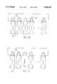
- FIGS. 5A and 5Billustrate a main storage accumulator battery of the station according to the invention illustrated in FIG. 4.
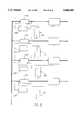
- FIG. 6illustrates the general organization of the station according to the invention.
- FIG. 7illustrates the customized storage of the station according to the invention.
- FIG. 8illustrates a variant of the customized storage of FIG. 7.
- FIG. 9illustrates a variant of the station according to the invention (the main storage being eliminated).
- FIG. 10illustrates a variant of the customized storage according to the invention (a single customized storage battery).
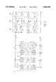
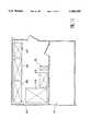
- FIG. 11illustrates the practical organization of a station according to the invention.
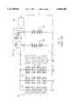
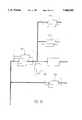
- FIG. 4shows the general principle of the customized storage, high voltage, photovoltaic power station according to the invention. It comprises photovoltaic solar modules 10, which are unitary voltage modules, e.g. of 55 V, in series-parallel connection.
- photovoltaic solar modules 10which are unitary voltage modules, e.g. of 55 V, in series-parallel connection.
- the loadtotal permanent power consumed
- these groups Bi of four modulesare connected in parallel.
- the advantage of these modulesis that their unitary voltage, which does not correspond to the "standard commercial" voltages means that their theft has no interest for potential users.
- the total voltage of a branch (220 V DC)is also dissuasive for theft.
- a battery charging regulator 31which, as for a 48 V regulation, serves to control the voltages at the end of the charging and discharging of a main storage battery 32 and in general terms ensures the full charging of said battery and its protection. It also gives alarms in the case of an operating anomaly of the system. Its design is simpler than a 48 V regulator, because the regulating function on the load is not necessary in this type of station.
- the main storage battery 32can be of the high electrolyte reserve, stationary type (solar battery), or the sealed type (no maintenance) or the cadmium-nickel type. Its operating voltage relative to the photovoltaic modules is 220 V nominal. It is therefore constituted by 2 or 1.2 V components, as a function of the battery type used and its capacity is a function of the charge and the desired duration of in operation without insolation (taking account of the customized storage defined hereinafter). For the same duration, it is pointed out that a 220 V station has a battery, whose capacity is four times lower than that of a 48 V battery.
- FIGS. 5A and 5Bwhich is difficult to envisage with 48 V due to the compared capacities). It therefore becomes unnecessary to duplicate the storage battery, FIG. 5B corresponding to the breaking of a 2 V component (arrow 42).
- FIG. 5Bcorresponding to the breaking of a 2 V component (arrow 42).
- One of the original features of this stationis its customized or distributed storage device 33. A link between the main storage device 33 and the personalized storage device is provided under high voltage. The voltage drop is much less than with 48 V, so that it is possible to use cables with smaller cross-sections and in particular to increase the distance between the photovoltaic solar modules, the regulator, the main battery, and the remainder of the station.
- FIG. 6shows all the photovoltaic solar modules or solar field 45, a shelter 46 containing the customized batteries Bpi . . . Bpn, a main battery Bp, DC/DC converters Cl . . . Cn, a charging regulator RC, the load and a link 47.
- a reference load regulating means 35FIG. 4).
- the final loadis supplied with multiple voltages and the energy balance thereof has been established beforehand (necessary voltages, necessary Currents and desired operational duration on a source by source basis). This is followed by the calculation of the necessary number of DC/DC converters 34 on a source-by-source basis, which are connected in parallel and with them is associated a battery having an adequate capacity to ensure the sought duration, as shown in FIG. 7, which shows:
- Photovoltaic solar modules with a nominal voltage e.g. close to 55 Vexcept for the solar panel size, nothing prevents the use of unitary modules of 110 V), the aim being to dissuade theft of the modules both due to the voltage level and the panel size.
- the output voltage of the modulesis 12 or 24 V.
- a highly simplified charging regulatorcompared with the standard 48 V regulator.
- Different batterieswhich are either of the large electrolyte reserve, lead, stationary type, optionally with an electrolyte brazing system (to prevent stratification), or sealed (without maintenance), or of the cadmium-nickel type.
- the special feature of the systemis that of placing bypass diodes on each storage battery component, so as to ensure operational continuity in the case of component breakage.
- Different DC/DC convertersstarting from 220 V DC, supply the voltages necessary for the load.
- This type of converteris very easy to implement, e.g. for an input voltage varying between 180 and 370 V, unitary modules exist which, at the out-put, supply the requisite voltages to within ⁇ 2% with an efficiency of approximately 85% and for different unitary power levels such as 50 W, 75 W, 100 W, 150 W, 200 W, 300 W.
- These converterscan be connected in parallel or series. They operate in a temperature range between -20° and +85° C. (converter base temperature). This temperature range makes it possible to make the equipments operate under natural ambient conditions, even in equatorial or tropical climates.
- the separation of the converters from the loadas shown in FIG.
- Customized storage batterieseither of the large electrolyte reserve, stationary, lead, solar battery type, or of the gas recombination, sealed type, or the cadmium-nickel type may be used.
- the charging and maintenance of the batteriesare obtained by DC/DC converters, whose output voltage is regulatable from 20 to 60%.
- the photovoltaic solar modules 10supply, on the one hand the different DC/DC converters and on the other hard charge the main battery (220 V DC) across the high voltage charging regulator. If necessary, the DC/DC converters can also supply the load and recharge the different associated batteries. In a normal operating period, these batteries customized to each source are simply maintained in their full charging state. In the noninsolation or non-sunny period (night or lack of or little sunshine), the main battery supplies the ampere-hours necessary for the supply of the DC/DC converters.
- the main batteryis disconnected (function of the high voltage charging regulator) and the customized batteries take over, ensuring the supply of the ampere-hours to the load. If this second operating period of the battery exceeds the time fixed by the initial dimensioning, a security system disconnects these batteries so as to protect them against a deep discharge.
- the main batteryWhen the sunshine returns, the main battery is automatically reconnected and recharges, and in parallel, the converters are supplied. They automatically pass into the charging position and recharge the associated batteries, whilst at the same time supplying the load.
- a variant shown in FIG. 8could consist of customizing certain converters 58 in order to allocate to them a more specific charging function (higher charging voltage than on the load). Such a function is known from 48 V rectifier/charger systems.
- the batteryIn the case of a one day operational duration, the battery is highly loaded (45% of daily discharge). It is therefore necessary to choose a battery having a very good cyclic loading resistance, which is not the case for a duration of seven days with a daily discharge of 8%.
- Source 2 V/75 Acapacity for 5 days (C/120) 9000 Ah, i.e. in C/10:6430 Ah
- Source 5 V/120 Acapacity for 5 days (C/120) 14 4000 Ah, i.e. in C/10:10 286 Ah
- Source 12 V/10 Acapacity for 5 days (C/120) 1 200 Ah, i.e. in C/10:860 Ah
- Source 28 V/14 Acapacity for 5 days (C/120) 480 Ah, i.e. in C/10:345 Ah
- FIG. 7corresponds to a first configuration in which the converter is equipped at the outset with an automatic charge/maintenance passage system corresponding to a voltage change applied to the storage batteries.
- At the output of the converter-customized battery meansthere is a filtering-regulating circuit for regulating the voltage on the load.
- the voltage of the batterywill vary throughout its charging/discharging cycle, whereas e.g. it is necessary to ensure a constant supply of 5.15 V on the source (5 V/120 A), hence the need of providing a regulating circuit, such as is well known to the expert.
- a differential amplifiercan amplify the difference between the reference voltage, obtained from a Zener diode and the voltage measured at the battery/converter output.
- the reference voltagecan be brought to zero by a microprocessor or by a voltage presence detector thus inhibiting the action of the regulator. In the case of a discharge on batteries, it is the latter circuit which regulates the discharge voltage, whereas the microprocessor limits its duration.
- the DC/DC convertersare all connected in parallel.
- the capacity of the meansmust take account of the permanent current particular to the load, plus the recharging current of the storage batteries.
- the recharging timeis a calculation element for the dimensioning of the converters. A recharging period of ten days is adopted in the considered example.
- a minimum (n+1) convertersis provided in order to ensure a high reliability of the means.
- the unitary power of each convertercan be determined as a function of the overall dimensions given or a desired standardization.
- 5 V source5 200 W, 220/5 V converters
- FIG. 8uses the same references as in FIG. 7, but charging converters 58 are additionally shown.
- the output voltage of the converterscan be regulated independently of the-output voltage of the converters direct on the load.
- the redundancy of the convertersis calculated solely on the basis of the needs of the load, the charging circuit of the batteries being considered as a reserve circuit. This leads to an equipment gain.
- V/120 A sourceV/120 A source
- Another variant of the inventionconsists of storing the power solely on one or two customized batteries and ensuring the supply of the sources by converters adapted to the storage sources, as shown in FIG. 10, where the same references as in FIG. 8 are used.
- the relay telecommunications station considered in exemplified manneris at an isolated location (i.e. isolated from any commercial electric power distribution network) and below the equator.
- FIG. 6gives an idea of the installation of the different components of the station using the configuration of FIG. 4, which is the most complete (but also the most disadvantageous as regards equipment). It is possible to see the solar field 45 remote from the shelter 46 and constituted by two separate compartments or parts, namely the telecommunications equipment room 47 and the power room 48.
- the inventionis characterized in that the telecommunications equipments are completely separate from the power equipments.
- the heat evolved by the telecommunications equipmentsis minimal, so that no ventilation is necessary, a completely sealed and thermally insulated enclosure being provided.
- This arrangementavoids the well known problems existing under equatorial climatic conditions, i.e. humidity, heat, penetration of dust, insects, rodents, etc.
- the plan of the power room 64is shown in FIG. 11, taking account of the real dimensions of the batteries and converters, i.e. 220 V batteries (65) and (66), 2 V batteries (67), 5 V batteries (68), 12 and 28 V batteries (69) and converter bay (70).
- At 71is shown the telecommunications equipment room.
Landscapes
- Engineering & Computer Science (AREA)
- Power Engineering (AREA)
- Electromagnetism (AREA)
- Sustainable Energy (AREA)
- Sustainable Development (AREA)
- Physics & Mathematics (AREA)
- Life Sciences & Earth Sciences (AREA)
- General Physics & Mathematics (AREA)
- Radar, Positioning & Navigation (AREA)
- Automation & Control Theory (AREA)
- Charge And Discharge Circuits For Batteries Or The Like (AREA)
- Optical Communication System (AREA)
- Control Of Electrical Variables (AREA)
Abstract
Description
______________________________________ Location: CONGO (Northern axis of the Congo: OWENDO) Latitude: 1° north Longitude: -10° west Insolation: monthly mean values of daily insolation received by a horizontal surface on the site (kwh/m.sup.2·d) January 5.92 February 6.21 March 6.25 April 5.14 May 4.83 June 4.59 July 4.67 August 5.65 September 5.31 October 5.26 November 5.53 December 5.29 Power needs: daily needs 25882.4 Wh/d utilization voltage 220 V current needs 123.5 Ah/d Solar generator: total peak power: 6600 Wc at 25° C., 1 kW/m.sup.2, spectrum AM 1.5 module types: a) with 12 V v 48.5 Wc modules: i.e. 8 serial-parallel, 17 modules per series (136 modules) b) with 55 V × 207 Wc modules: i.e. 8 serial-parallel, 4 modules per series (32 modules) Available current (Ah/d) for optimum inclination of 5°: January 135 February 141 March 140 April 114 May 106 June 100 July 102 August 124 September 118 October 119 November 126 December 121 Main storage: 1 day without sun: 130 Ah (nominal capacity for a 10 hour discharge) 220 V nominal voltage (discharge up to 214.5 V) 45% average discharge rate 80% maximum discharge rate 2 days without sun: 260 Ah (nominal capacity for a 10 hour discharge) 220 V nominal voltage (discharge up to 214.5 V) 23% average discharge rate 80% maximum discharge rate 7 days without sun: 744 Ah (nominal capacity for a 10 hour discharge) 220 V nominal voltage (discharge up to 214.5 V) 8% average discharge rate 80% maximum discharge rate ______________________________________
______________________________________ 2 V/75 A (150 W) 5 V/120 A (600 W) 12 V/10 A (120 W) 28 V/4 A (112 W) Total: 982 W.sup. (permanent) ______________________________________
(3*100)+(5*20.0)+3*75)+(3*75)=1750W Configuration 1
(3*75)+50+(4*200)+200+(4*50)+50+(3*50)+50=1725 W Configuration 2
Claims (16)
Applications Claiming Priority (2)
| Application Number | Priority Date | Filing Date | Title |
|---|---|---|---|
| FR9503490AFR2732170B1 (en) | 1995-03-24 | 1995-03-24 | HIGH VOLTAGE PHOTOVOLTAIC ENERGY STATION WITH PERSONALIZED STORAGE |
| FR9503490 | 1995-03-24 |
Publications (1)
| Publication Number | Publication Date |
|---|---|
| US5684385Atrue US5684385A (en) | 1997-11-04 |
Family
ID=9477397
Family Applications (1)
| Application Number | Title | Priority Date | Filing Date |
|---|---|---|---|
| US08/611,134Expired - LifetimeUS5684385A (en) | 1995-03-24 | 1996-03-05 | Customized storage, high voltage, photovoltaic power station |
Country Status (4)
| Country | Link |
|---|---|
| US (1) | US5684385A (en) |
| EP (1) | EP0734111B1 (en) |
| DE (1) | DE69636317T2 (en) |
| FR (1) | FR2732170B1 (en) |
Cited By (102)
| Publication number | Priority date | Publication date | Assignee | Title |
|---|---|---|---|---|
| US5959370A (en)* | 1998-07-15 | 1999-09-28 | Pardo; Herbert | Differential voltage battery DC power supply |
| US6093885A (en)* | 1998-03-03 | 2000-07-25 | Canon Kabushiki Kaisha | Photovoltaic power generating system |
| US6103970A (en)* | 1998-08-20 | 2000-08-15 | Tecstar Power Systems, Inc. | Solar cell having a front-mounted bypass diode |
| US6156967A (en)* | 1998-06-04 | 2000-12-05 | Tecstar Power Systems, Inc. | Modular glass covered solar cell array |
| US6169678B1 (en)* | 1999-01-28 | 2001-01-02 | Canon Kabushiki Kaisha | Photovoltaic power generation apparatus and control method thereof |
| US6188146B1 (en)* | 1998-05-21 | 2001-02-13 | Paris Michaels | Supplying power for communications devices |
| US6278054B1 (en) | 1998-05-28 | 2001-08-21 | Tecstar Power Systems, Inc. | Solar cell having an integral monolithically grown bypass diode |
| US6331671B1 (en)* | 1999-02-25 | 2001-12-18 | Canon Kabushiki Kaisha | Installation structure of solar cell module array, installation method of solar cell module, and sunlight power generation system |
| WO2002086649A1 (en)* | 2001-04-20 | 2002-10-31 | Erik Kai Lund | Regulator device |
| US6583522B1 (en)* | 2000-09-27 | 2003-06-24 | Worldwater Corp. | Switchable multiple source power supply |
| US6686533B2 (en) | 2002-01-29 | 2004-02-03 | Israel Aircraft Industries Ltd. | System and method for converting solar energy to electricity |
| AU770832B2 (en)* | 1998-05-21 | 2004-03-04 | Paris Michaels | Supplying power for communications devices |
| US6704626B1 (en) | 1999-04-02 | 2004-03-09 | Herzog Contracting Corp. | Logistics system and method with position control |
| US20050235864A1 (en)* | 2004-04-22 | 2005-10-27 | Herzog Contracting Corp. | Method for delivering replacement rail ties using GPS techniques |
| US20050278982A1 (en)* | 2004-06-17 | 2005-12-22 | Herzog Contracting Corp. | Method and apparatus for applying railway ballast |
| US20070040519A1 (en)* | 2005-08-19 | 2007-02-22 | Delta Electronics Inc. | Motor driving method and device thereof |
| US7283110B2 (en) | 2002-10-07 | 2007-10-16 | Samsung Sdi Co., Ltd. | Flat panel display |
| WO2008046370A1 (en)* | 2006-10-19 | 2008-04-24 | Fpe Fischer Gmbh | Method and circuit for monitoring a solar panel for theft |
| US20080122518A1 (en)* | 2006-11-27 | 2008-05-29 | Besser David A | Multi-Source, Multi-Load Systems with a Power Extractor |
| US20080122449A1 (en)* | 2006-11-27 | 2008-05-29 | Besser David A | Power extractor for impedance matching |
| US20080121272A1 (en)* | 2006-11-27 | 2008-05-29 | Besser David A | System and apparatuses with multiple power extractors coupled to different power sources |
| US20080164761A1 (en)* | 2007-01-08 | 2008-07-10 | O'bryant Greg | Uninterruptable power supply |
| US20080179949A1 (en)* | 2006-11-27 | 2008-07-31 | Besser David A | Power extractor detecting a power change |
| US20080179961A1 (en)* | 2007-01-26 | 2008-07-31 | Kimball Jonathan W | Apparatus and method for controlling a power supply |
| WO2009048715A1 (en)* | 2007-10-09 | 2009-04-16 | Ford Global Technologies, Llc | Solar charged hybrid power system |
| US20100019578A1 (en)* | 2008-07-26 | 2010-01-28 | Semikron Elektronik Gmbh & Co. Kg | Power Converter for Solar Electrical Current Installations and Method for Controlling it |
| US20100089442A1 (en)* | 2008-07-25 | 2010-04-15 | Matthew Beasley | Three-terminal Two-junction Phtovoltaic Cells and Method of Use |
| US20100259211A1 (en)* | 2009-04-08 | 2010-10-14 | Jen Yen Yen | Recharge battery safely chargeable with solar energy |
| US8174856B2 (en) | 2011-04-27 | 2012-05-08 | Solarbridge Technologies, Inc. | Configurable power supply assembly |
| WO2012000496A3 (en)* | 2010-06-09 | 2012-07-19 | Danfoss Solar Inverters A/S | Solar power plant with increased useful life |
| US8279649B2 (en) | 2010-10-11 | 2012-10-02 | Solarbridge Technologies, Inc. | Apparatus and method for controlling a power inverter |
| US8284574B2 (en) | 2011-10-17 | 2012-10-09 | Solarbridge Technologies, Inc. | Method and apparatus for controlling an inverter using pulse mode control |
| US8325499B2 (en) | 2007-10-11 | 2012-12-04 | Solarbridge Technologies, Inc. | Methods for minimizing double-frequency ripple power in single-phase power conditioners |
| US20130015805A1 (en)* | 2010-06-04 | 2013-01-17 | Triune Ip Llc | Energy storage element link and monitor |
| US8462518B2 (en) | 2009-10-12 | 2013-06-11 | Solarbridge Technologies, Inc. | Power inverter docking system for photovoltaic modules |
| US8503200B2 (en) | 2010-10-11 | 2013-08-06 | Solarbridge Technologies, Inc. | Quadrature-corrected feedforward control apparatus and method for DC-AC power conversion |
| US20130207474A1 (en)* | 2010-06-04 | 2013-08-15 | Aeg Power Solutions B.V. | Matrix connection device for photovoltaic panels and/or wind turbines |
| US8611107B2 (en) | 2011-04-27 | 2013-12-17 | Solarbridge Technologies, Inc. | Method and system for controlling a multi-stage power inverter |
| US20140058688A1 (en)* | 2012-08-27 | 2014-02-27 | Hitachi, Ltd. | Failure Diagnosis Method for Photovoltaic Power Generation System |
| US8669675B2 (en) | 2003-05-28 | 2014-03-11 | Beacon Power, Llc | Power converter for a solar panel |
| US8824178B1 (en) | 2009-12-31 | 2014-09-02 | Solarbridge Technologies, Inc. | Parallel power converter topology |
| US8842454B2 (en) | 2010-11-29 | 2014-09-23 | Solarbridge Technologies, Inc. | Inverter array with localized inverter control |
| US8922185B2 (en) | 2011-07-11 | 2014-12-30 | Solarbridge Technologies, Inc. | Device and method for global maximum power point tracking |
| US9065354B2 (en) | 2011-04-27 | 2015-06-23 | Sunpower Corporation | Multi-stage power inverter for power bus communication |
| US9093919B2 (en) | 2009-07-31 | 2015-07-28 | Sunpower Corporation | Apparatus for converting direct current to alternating current using a frequency converter |
| US9112379B2 (en) | 2006-12-06 | 2015-08-18 | Solaredge Technologies Ltd. | Pairing of components in a direct current distributed power generation system |
| US9130401B2 (en) | 2006-12-06 | 2015-09-08 | Solaredge Technologies Ltd. | Distributed power harvesting systems using DC power sources |
| US9160408B2 (en) | 2010-10-11 | 2015-10-13 | Sunpower Corporation | System and method for establishing communication with an array of inverters |
| US9235228B2 (en) | 2012-03-05 | 2016-01-12 | Solaredge Technologies Ltd. | Direct current link circuit |
| US9276635B2 (en) | 2012-06-29 | 2016-03-01 | Sunpower Corporation | Device, system, and method for communicating with a power inverter using power line communications |
| US9291696B2 (en) | 2007-12-05 | 2016-03-22 | Solaredge Technologies Ltd. | Photovoltaic system power tracking method |
| US9318974B2 (en) | 2014-03-26 | 2016-04-19 | Solaredge Technologies Ltd. | Multi-level inverter with flying capacitor topology |
| US9362743B2 (en) | 2008-05-05 | 2016-06-07 | Solaredge Technologies Ltd. | Direct current power combiner |
| US9368964B2 (en) | 2006-12-06 | 2016-06-14 | Solaredge Technologies Ltd. | Distributed power system using direct current power sources |
| US9401599B2 (en) | 2010-12-09 | 2016-07-26 | Solaredge Technologies Ltd. | Disconnection of a string carrying direct current power |
| US9407161B2 (en) | 2007-12-05 | 2016-08-02 | Solaredge Technologies Ltd. | Parallel connected inverters |
| US9467063B2 (en) | 2010-11-29 | 2016-10-11 | Sunpower Corporation | Technologies for interleaved control of an inverter array |
| US9537445B2 (en) | 2008-12-04 | 2017-01-03 | Solaredge Technologies Ltd. | Testing of a photovoltaic panel |
| US9543889B2 (en) | 2006-12-06 | 2017-01-10 | Solaredge Technologies Ltd. | Distributed power harvesting systems using DC power sources |
| US9548619B2 (en) | 2013-03-14 | 2017-01-17 | Solaredge Technologies Ltd. | Method and apparatus for storing and depleting energy |
| US9564835B2 (en) | 2013-03-15 | 2017-02-07 | Sunpower Corporation | Inverter communications using output signal |
| US9584044B2 (en) | 2013-03-15 | 2017-02-28 | Sunpower Corporation | Technologies for converter topologies |
| US9590526B2 (en) | 2006-12-06 | 2017-03-07 | Solaredge Technologies Ltd. | Safety mechanisms, wake up and shutdown methods in distributed power installations |
| US9647442B2 (en) | 2010-11-09 | 2017-05-09 | Solaredge Technologies Ltd. | Arc detection and prevention in a power generation system |
| US9644993B2 (en) | 2006-12-06 | 2017-05-09 | Solaredge Technologies Ltd. | Monitoring of distributed power harvesting systems using DC power sources |
| US9673711B2 (en) | 2007-08-06 | 2017-06-06 | Solaredge Technologies Ltd. | Digital average input current control in power converter |
| US9680304B2 (en) | 2006-12-06 | 2017-06-13 | Solaredge Technologies Ltd. | Method for distributed power harvesting using DC power sources |
| US9812984B2 (en) | 2012-01-30 | 2017-11-07 | Solaredge Technologies Ltd. | Maximizing power in a photovoltaic distributed power system |
| US9819178B2 (en) | 2013-03-15 | 2017-11-14 | Solaredge Technologies Ltd. | Bypass mechanism |
| US9831824B2 (en) | 2007-12-05 | 2017-11-28 | SolareEdge Technologies Ltd. | Current sensing on a MOSFET |
| US9853538B2 (en) | 2007-12-04 | 2017-12-26 | Solaredge Technologies Ltd. | Distributed power harvesting systems using DC power sources |
| US9853565B2 (en) | 2012-01-30 | 2017-12-26 | Solaredge Technologies Ltd. | Maximized power in a photovoltaic distributed power system |
| US9866098B2 (en) | 2011-01-12 | 2018-01-09 | Solaredge Technologies Ltd. | Serially connected inverters |
| US9869701B2 (en) | 2009-05-26 | 2018-01-16 | Solaredge Technologies Ltd. | Theft detection and prevention in a power generation system |
| US9876430B2 (en) | 2008-03-24 | 2018-01-23 | Solaredge Technologies Ltd. | Zero voltage switching |
| US9923516B2 (en) | 2012-01-30 | 2018-03-20 | Solaredge Technologies Ltd. | Photovoltaic panel circuitry |
| US9941813B2 (en) | 2013-03-14 | 2018-04-10 | Solaredge Technologies Ltd. | High frequency multi-level inverter |
| US9960667B2 (en) | 2006-12-06 | 2018-05-01 | Solaredge Technologies Ltd. | System and method for protection during inverter shutdown in distributed power installations |
| US9966766B2 (en) | 2006-12-06 | 2018-05-08 | Solaredge Technologies Ltd. | Battery power delivery module |
| US10115841B2 (en) | 2012-06-04 | 2018-10-30 | Solaredge Technologies Ltd. | Integrated photovoltaic panel circuitry |
| US10230310B2 (en) | 2016-04-05 | 2019-03-12 | Solaredge Technologies Ltd | Safety switch for photovoltaic systems |
| US10396662B2 (en) | 2011-09-12 | 2019-08-27 | Solaredge Technologies Ltd | Direct current link circuit |
| WO2020087020A1 (en)* | 2018-10-26 | 2020-04-30 | Ed Rodriguez | Supplemental renewable energy system |
| US10673222B2 (en) | 2010-11-09 | 2020-06-02 | Solaredge Technologies Ltd. | Arc detection and prevention in a power generation system |
| US10673229B2 (en) | 2010-11-09 | 2020-06-02 | Solaredge Technologies Ltd. | Arc detection and prevention in a power generation system |
| US10931119B2 (en) | 2012-01-11 | 2021-02-23 | Solaredge Technologies Ltd. | Photovoltaic module |
| US11018623B2 (en) | 2016-04-05 | 2021-05-25 | Solaredge Technologies Ltd. | Safety switch for photovoltaic systems |
| US11177663B2 (en) | 2016-04-05 | 2021-11-16 | Solaredge Technologies Ltd. | Chain of power devices |
| US20220021215A1 (en)* | 2020-07-15 | 2022-01-20 | Ururaki Inc | Power transmission method and system |
| US11264947B2 (en) | 2007-12-05 | 2022-03-01 | Solaredge Technologies Ltd. | Testing of a photovoltaic panel |
| US11296650B2 (en) | 2006-12-06 | 2022-04-05 | Solaredge Technologies Ltd. | System and method for protection during inverter shutdown in distributed power installations |
| US11309832B2 (en) | 2006-12-06 | 2022-04-19 | Solaredge Technologies Ltd. | Distributed power harvesting systems using DC power sources |
| US11569660B2 (en) | 2006-12-06 | 2023-01-31 | Solaredge Technologies Ltd. | Distributed power harvesting systems using DC power sources |
| US11569659B2 (en) | 2006-12-06 | 2023-01-31 | Solaredge Technologies Ltd. | Distributed power harvesting systems using DC power sources |
| US11687112B2 (en) | 2006-12-06 | 2023-06-27 | Solaredge Technologies Ltd. | Distributed power harvesting systems using DC power sources |
| US11728768B2 (en) | 2006-12-06 | 2023-08-15 | Solaredge Technologies Ltd. | Pairing of components in a direct current distributed power generation system |
| US11735910B2 (en) | 2006-12-06 | 2023-08-22 | Solaredge Technologies Ltd. | Distributed power system using direct current power sources |
| US11855231B2 (en) | 2006-12-06 | 2023-12-26 | Solaredge Technologies Ltd. | Distributed power harvesting systems using DC power sources |
| US11881814B2 (en) | 2005-12-05 | 2024-01-23 | Solaredge Technologies Ltd. | Testing of a photovoltaic panel |
| US11888387B2 (en) | 2006-12-06 | 2024-01-30 | Solaredge Technologies Ltd. | Safety mechanisms, wake up and shutdown methods in distributed power installations |
| US12057807B2 (en) | 2016-04-05 | 2024-08-06 | Solaredge Technologies Ltd. | Chain of power devices |
| US12418177B2 (en) | 2009-10-24 | 2025-09-16 | Solaredge Technologies Ltd. | Distributed power system using direct current power sources |
Families Citing this family (5)
| Publication number | Priority date | Publication date | Assignee | Title |
|---|---|---|---|---|
| US6628011B2 (en)* | 2000-07-28 | 2003-09-30 | International Power System, Inc. | DC to DC converter and power management system |
| CN101764414B (en)* | 2010-03-10 | 2012-03-21 | 江苏省电力设计院 | Photovoltaic electric station grid connection capacity optimization and control method based on four-element constraint method |
| FR2978533A1 (en) | 2011-07-26 | 2013-02-01 | Jacquis Suzanne | HEAT-RENEWABLE ENERGY STORAGE DEVICE AND TRI GENERATION RESTITUTION METHOD |
| CN106787095B (en)* | 2016-12-06 | 2023-06-13 | 柳州铁道职业技术学院 | Household multi-gear solar charger circuit |
| CN113991823B (en)* | 2021-12-01 | 2024-07-26 | 宁波大学 | Highway photovoltaic charging system without service area and construction method thereof |
Citations (4)
| Publication number | Priority date | Publication date | Assignee | Title |
|---|---|---|---|---|
| GB2229736A (en)* | 1989-03-17 | 1990-10-03 | Polynesie Francaise | Corrosion protection of module frame of photovoltaic generator |
| US4963811A (en)* | 1987-12-10 | 1990-10-16 | Weber Hans R | Method and apparatus for powering electrical and electronic consuming devices with solar energy |
| US5131341A (en)* | 1990-12-03 | 1992-07-21 | Edwin Newman | Solar powered electric ship system |
| US5184502A (en)* | 1991-06-17 | 1993-02-09 | Remote Power, Inc. | Helicopter installable, self-powered, modular, remote, telemetry package |
Family Cites Families (4)
| Publication number | Priority date | Publication date | Assignee | Title |
|---|---|---|---|---|
| FR2438934A1 (en)* | 1978-10-09 | 1980-05-09 | Accumulateurs Fixes | DEVICE FOR REGULATING THE CHARGE OF A BATTERY |
| US4281278A (en)* | 1979-12-05 | 1981-07-28 | Rca Corporation | Redundant battery protection system |
| US4494063A (en)* | 1982-12-23 | 1985-01-15 | Rca Corporation | Satellite dual bus power system |
| DE3319511A1 (en)* | 1983-05-28 | 1984-11-29 | Hans Kurt Dr.-Ing. 6233 Kelkheim Köthe | Battery-aided power supply system I |
- 1995
- 1995-03-24FRFR9503490Apatent/FR2732170B1/ennot_activeExpired - Lifetime
- 1996
- 1996-03-05USUS08/611,134patent/US5684385A/ennot_activeExpired - Lifetime
- 1996-03-22EPEP96400610Apatent/EP0734111B1/ennot_activeExpired - Lifetime
- 1996-03-22DEDE69636317Tpatent/DE69636317T2/ennot_activeExpired - Lifetime
Patent Citations (4)
| Publication number | Priority date | Publication date | Assignee | Title |
|---|---|---|---|---|
| US4963811A (en)* | 1987-12-10 | 1990-10-16 | Weber Hans R | Method and apparatus for powering electrical and electronic consuming devices with solar energy |
| GB2229736A (en)* | 1989-03-17 | 1990-10-03 | Polynesie Francaise | Corrosion protection of module frame of photovoltaic generator |
| US5131341A (en)* | 1990-12-03 | 1992-07-21 | Edwin Newman | Solar powered electric ship system |
| US5184502A (en)* | 1991-06-17 | 1993-02-09 | Remote Power, Inc. | Helicopter installable, self-powered, modular, remote, telemetry package |
Non-Patent Citations (4)
| Title |
|---|
| Intelec 10th International Telecommunications Energy Conference, pp. 475 480, Oct. 30 Nov. 2, 1988, R. De Gregorio, et al., First Results of an Aimed Research Carried Out by the Italian P.T. Ministry Related to a Prototypical Photovoltaic Hybrid Power System for TLC .* |
| Intelec 10th International Telecommunications Energy Conference, pp. 475-480, Oct. 30-Nov. 2, 1988, R. De Gregorio, et al., "First Results of an Aimed Research Carried Out by the Italian P.T. Ministry Related to a Prototypical Photovoltaic Hybrid Power System for TLC". |
| Proceedings of the 28th Intersociety Energy Conversion Engineering Conference, vol. 1, pp. 1.414 1.419, Aug. 8, 1993, A. Ahmad, et al., The X Ray Timing Explorer (XTE) Power System .* |
| Proceedings of the 28th Intersociety Energy Conversion Engineering Conference, vol. 1, pp. 1.414-1.419, Aug. 8, 1993, A. Ahmad, et al., "The X-Ray Timing Explorer (XTE) Power System". |
Cited By (255)
| Publication number | Priority date | Publication date | Assignee | Title |
|---|---|---|---|---|
| US6093885A (en)* | 1998-03-03 | 2000-07-25 | Canon Kabushiki Kaisha | Photovoltaic power generating system |
| AU770832B2 (en)* | 1998-05-21 | 2004-03-04 | Paris Michaels | Supplying power for communications devices |
| US6188146B1 (en)* | 1998-05-21 | 2001-02-13 | Paris Michaels | Supplying power for communications devices |
| US6278054B1 (en) | 1998-05-28 | 2001-08-21 | Tecstar Power Systems, Inc. | Solar cell having an integral monolithically grown bypass diode |
| US6600100B2 (en) | 1998-05-28 | 2003-07-29 | Emcore Corporation | Solar cell having an integral monolithically grown bypass diode |
| US6359210B2 (en) | 1998-05-28 | 2002-03-19 | Tecstar Power System, Inc. | Solar cell having an integral monolithically grown bypass diode |
| US6407327B1 (en) | 1998-06-04 | 2002-06-18 | Tecstar Power Systems, Inc. | Modular, glass covered solar cell array |
| US6156967A (en)* | 1998-06-04 | 2000-12-05 | Tecstar Power Systems, Inc. | Modular glass covered solar cell array |
| US5959370A (en)* | 1998-07-15 | 1999-09-28 | Pardo; Herbert | Differential voltage battery DC power supply |
| US6103970A (en)* | 1998-08-20 | 2000-08-15 | Tecstar Power Systems, Inc. | Solar cell having a front-mounted bypass diode |
| US6617508B2 (en) | 1998-08-20 | 2003-09-09 | Emcore Corporation | Solar cell having a front-mounted bypass diode |
| US6326540B1 (en) | 1998-08-20 | 2001-12-04 | Tecstar Power Systems, Inc. | Solar cell having a front-mounted bypass diode |
| US6169678B1 (en)* | 1999-01-28 | 2001-01-02 | Canon Kabushiki Kaisha | Photovoltaic power generation apparatus and control method thereof |
| US6331671B1 (en)* | 1999-02-25 | 2001-12-18 | Canon Kabushiki Kaisha | Installation structure of solar cell module array, installation method of solar cell module, and sunlight power generation system |
| US6704626B1 (en) | 1999-04-02 | 2004-03-09 | Herzog Contracting Corp. | Logistics system and method with position control |
| US20040138788A1 (en)* | 1999-04-02 | 2004-07-15 | Herzog Stanley M. | Logistics system and method with position control |
| US20050216142A1 (en)* | 1999-04-02 | 2005-09-29 | Herzog Contracting Corp. | Logistics System and Method With Position Control |
| US6583522B1 (en)* | 2000-09-27 | 2003-06-24 | Worldwater Corp. | Switchable multiple source power supply |
| WO2002086649A1 (en)* | 2001-04-20 | 2002-10-31 | Erik Kai Lund | Regulator device |
| US6686533B2 (en) | 2002-01-29 | 2004-02-03 | Israel Aircraft Industries Ltd. | System and method for converting solar energy to electricity |
| US7283110B2 (en) | 2002-10-07 | 2007-10-16 | Samsung Sdi Co., Ltd. | Flat panel display |
| US11075518B2 (en) | 2003-05-28 | 2021-07-27 | Solaredge Technologies Ltd. | Power converter for a solar panel |
| US10135241B2 (en) | 2003-05-28 | 2018-11-20 | Solaredge Technologies, Ltd. | Power converter for a solar panel |
| US11824398B2 (en) | 2003-05-28 | 2023-11-21 | Solaredge Technologies Ltd. | Power converter for a solar panel |
| US10910834B2 (en) | 2003-05-28 | 2021-02-02 | Solaredge Technologies Ltd. | Power converter for a solar panel |
| US9438035B2 (en) | 2003-05-28 | 2016-09-06 | Solaredge Technologies Ltd. | Power converter for a solar panel |
| US11817699B2 (en) | 2003-05-28 | 2023-11-14 | Solaredge Technologies Ltd. | Power converter for a solar panel |
| US8669675B2 (en) | 2003-05-28 | 2014-03-11 | Beacon Power, Llc | Power converter for a solar panel |
| US11658508B2 (en) | 2003-05-28 | 2023-05-23 | Solaredge Technologies Ltd. | Power converter for a solar panel |
| US11476663B2 (en) | 2003-05-28 | 2022-10-18 | Solaredge Technologies Ltd. | Power converter for a solar panel |
| US20080163782A1 (en)* | 2004-04-22 | 2008-07-10 | Herzog Stanley M | Method for delivering replacement rail ties using gps techniques |
| US20050235864A1 (en)* | 2004-04-22 | 2005-10-27 | Herzog Contracting Corp. | Method for delivering replacement rail ties using GPS techniques |
| US7437997B2 (en) | 2004-04-22 | 2008-10-21 | Herzog Contracting Corp. | Method for delivering replacement rail ties using GPS techniques |
| US7152347B2 (en) | 2004-06-17 | 2006-12-26 | Herzog Contracting Corporation | Method and apparatus for applying railway ballast |
| US7707944B2 (en) | 2004-06-17 | 2010-05-04 | Herzog Contracting Corp. | Method and apparatus for applying railway ballast |
| US20050278982A1 (en)* | 2004-06-17 | 2005-12-22 | Herzog Contracting Corp. | Method and apparatus for applying railway ballast |
| US20070129858A1 (en)* | 2004-06-17 | 2007-06-07 | Herzog Stanley M | Method and apparatus for applying railway ballast |
| US7573213B2 (en)* | 2005-08-19 | 2009-08-11 | Delta Electronics Inc. | Motor driving method and device thereof |
| US20070040519A1 (en)* | 2005-08-19 | 2007-02-22 | Delta Electronics Inc. | Motor driving method and device thereof |
| US11881814B2 (en) | 2005-12-05 | 2024-01-23 | Solaredge Technologies Ltd. | Testing of a photovoltaic panel |
| WO2008046370A1 (en)* | 2006-10-19 | 2008-04-24 | Fpe Fischer Gmbh | Method and circuit for monitoring a solar panel for theft |
| US9130390B2 (en) | 2006-11-27 | 2015-09-08 | David A. Besser | Power extractor detecting power and voltage changes |
| US20080122449A1 (en)* | 2006-11-27 | 2008-05-29 | Besser David A | Power extractor for impedance matching |
| US20080179949A1 (en)* | 2006-11-27 | 2008-07-31 | Besser David A | Power extractor detecting a power change |
| US9431828B2 (en) | 2006-11-27 | 2016-08-30 | Xslent Energy Technologies | Multi-source, multi-load systems with a power extractor |
| US20080121272A1 (en)* | 2006-11-27 | 2008-05-29 | Besser David A | System and apparatuses with multiple power extractors coupled to different power sources |
| US10158233B2 (en) | 2006-11-27 | 2018-12-18 | Xslent Energy Technologies, Llc | Multi-source, multi-load systems with a power extractor |
| US7839025B2 (en) | 2006-11-27 | 2010-11-23 | Xslent Energy Technologies, Llc | Power extractor detecting a power change |
| US20080191675A1 (en)* | 2006-11-27 | 2008-08-14 | Besser David A | Power extractor detecting power and voltage changes |
| US7960870B2 (en) | 2006-11-27 | 2011-06-14 | Xslent Energy Technologies, Llc | Power extractor for impedance matching |
| US20080122518A1 (en)* | 2006-11-27 | 2008-05-29 | Besser David A | Multi-Source, Multi-Load Systems with a Power Extractor |
| US8013474B2 (en)* | 2006-11-27 | 2011-09-06 | Xslent Energy Technologies, Llc | System and apparatuses with multiple power extractors coupled to different power sources |
| US11201475B2 (en) | 2006-11-27 | 2021-12-14 | Apparent Labs, LLC | Multi-source, multi-load systems with a power extractor |
| US8212399B2 (en) | 2006-11-27 | 2012-07-03 | Xslent Energy Technologies, Llc | Power extractor with control loop |
| US20080191560A1 (en)* | 2006-11-27 | 2008-08-14 | Besser David A | Power extractor with control loop |
| US12027849B2 (en) | 2006-12-06 | 2024-07-02 | Solaredge Technologies Ltd. | Distributed power system using direct current power sources |
| US11569660B2 (en) | 2006-12-06 | 2023-01-31 | Solaredge Technologies Ltd. | Distributed power harvesting systems using DC power sources |
| US12046940B2 (en) | 2006-12-06 | 2024-07-23 | Solaredge Technologies Ltd. | Battery power control |
| US12032080B2 (en) | 2006-12-06 | 2024-07-09 | Solaredge Technologies Ltd. | Safety mechanisms, wake up and shutdown methods in distributed power installations |
| US9966766B2 (en) | 2006-12-06 | 2018-05-08 | Solaredge Technologies Ltd. | Battery power delivery module |
| US9960667B2 (en) | 2006-12-06 | 2018-05-01 | Solaredge Technologies Ltd. | System and method for protection during inverter shutdown in distributed power installations |
| US12027970B2 (en) | 2006-12-06 | 2024-07-02 | Solaredge Technologies Ltd. | Safety mechanisms, wake up and shutdown methods in distributed power installations |
| US10097007B2 (en) | 2006-12-06 | 2018-10-09 | Solaredge Technologies Ltd. | Method for distributed power harvesting using DC power sources |
| US11961922B2 (en) | 2006-12-06 | 2024-04-16 | Solaredge Technologies Ltd. | Distributed power harvesting systems using DC power sources |
| US11962243B2 (en) | 2006-12-06 | 2024-04-16 | Solaredge Technologies Ltd. | Method for distributed power harvesting using DC power sources |
| US11888387B2 (en) | 2006-12-06 | 2024-01-30 | Solaredge Technologies Ltd. | Safety mechanisms, wake up and shutdown methods in distributed power installations |
| US12107417B2 (en) | 2006-12-06 | 2024-10-01 | Solaredge Technologies Ltd. | Distributed power harvesting systems using DC power sources |
| US9960731B2 (en) | 2006-12-06 | 2018-05-01 | Solaredge Technologies Ltd. | Pairing of components in a direct current distributed power generation system |
| US11855231B2 (en) | 2006-12-06 | 2023-12-26 | Solaredge Technologies Ltd. | Distributed power harvesting systems using DC power sources |
| US12224706B2 (en) | 2006-12-06 | 2025-02-11 | Solaredge Technologies Ltd. | Pairing of components in a direct current distributed power generation system |
| US12276997B2 (en) | 2006-12-06 | 2025-04-15 | Solaredge Technologies Ltd. | Distributed power harvesting systems using DC power sources |
| US9948233B2 (en) | 2006-12-06 | 2018-04-17 | Solaredge Technologies Ltd. | Distributed power harvesting systems using DC power sources |
| US11735910B2 (en) | 2006-12-06 | 2023-08-22 | Solaredge Technologies Ltd. | Distributed power system using direct current power sources |
| US11728768B2 (en) | 2006-12-06 | 2023-08-15 | Solaredge Technologies Ltd. | Pairing of components in a direct current distributed power generation system |
| US11687112B2 (en) | 2006-12-06 | 2023-06-27 | Solaredge Technologies Ltd. | Distributed power harvesting systems using DC power sources |
| US11682918B2 (en) | 2006-12-06 | 2023-06-20 | Solaredge Technologies Ltd. | Battery power delivery module |
| US10230245B2 (en) | 2006-12-06 | 2019-03-12 | Solaredge Technologies Ltd | Battery power delivery module |
| US11658482B2 (en) | 2006-12-06 | 2023-05-23 | Solaredge Technologies Ltd. | Distributed power harvesting systems using DC power sources |
| US11598652B2 (en) | 2006-12-06 | 2023-03-07 | Solaredge Technologies Ltd. | Monitoring of distributed power harvesting systems using DC power sources |
| US11594880B2 (en) | 2006-12-06 | 2023-02-28 | Solaredge Technologies Ltd. | Distributed power harvesting systems using DC power sources |
| US9112379B2 (en) | 2006-12-06 | 2015-08-18 | Solaredge Technologies Ltd. | Pairing of components in a direct current distributed power generation system |
| US10447150B2 (en) | 2006-12-06 | 2019-10-15 | Solaredge Technologies Ltd. | Distributed power harvesting systems using DC power sources |
| US9130401B2 (en) | 2006-12-06 | 2015-09-08 | Solaredge Technologies Ltd. | Distributed power harvesting systems using DC power sources |
| US11594881B2 (en) | 2006-12-06 | 2023-02-28 | Solaredge Technologies Ltd. | Distributed power harvesting systems using DC power sources |
| US10637393B2 (en) | 2006-12-06 | 2020-04-28 | Solaredge Technologies Ltd. | Distributed power harvesting systems using DC power sources |
| US11594882B2 (en) | 2006-12-06 | 2023-02-28 | Solaredge Technologies Ltd. | Distributed power harvesting systems using DC power sources |
| US11579235B2 (en) | 2006-12-06 | 2023-02-14 | Solaredge Technologies Ltd. | Safety mechanisms, wake up and shutdown methods in distributed power installations |
| US11575260B2 (en) | 2006-12-06 | 2023-02-07 | Solaredge Technologies Ltd. | Distributed power harvesting systems using DC power sources |
| US11575261B2 (en) | 2006-12-06 | 2023-02-07 | Solaredge Technologies Ltd. | Distributed power harvesting systems using DC power sources |
| US11569659B2 (en) | 2006-12-06 | 2023-01-31 | Solaredge Technologies Ltd. | Distributed power harvesting systems using DC power sources |
| US12068599B2 (en) | 2006-12-06 | 2024-08-20 | Solaredge Technologies Ltd. | System and method for protection during inverter shutdown in distributed power installations |
| US11476799B2 (en) | 2006-12-06 | 2022-10-18 | Solaredge Technologies Ltd. | Distributed power harvesting systems using DC power sources |
| US9368964B2 (en) | 2006-12-06 | 2016-06-14 | Solaredge Technologies Ltd. | Distributed power system using direct current power sources |
| US12281919B2 (en) | 2006-12-06 | 2025-04-22 | Solaredge Technologies Ltd. | Monitoring of distributed power harvesting systems using DC power sources |
| US11309832B2 (en) | 2006-12-06 | 2022-04-19 | Solaredge Technologies Ltd. | Distributed power harvesting systems using DC power sources |
| US9853490B2 (en) | 2006-12-06 | 2017-12-26 | Solaredge Technologies Ltd. | Distributed power system using direct current power sources |
| US12316274B2 (en) | 2006-12-06 | 2025-05-27 | Solaredge Technologies Ltd. | Pairing of components in a direct current distributed power generation system |
| US11296650B2 (en) | 2006-12-06 | 2022-04-05 | Solaredge Technologies Ltd. | System and method for protection during inverter shutdown in distributed power installations |
| US10673253B2 (en) | 2006-12-06 | 2020-06-02 | Solaredge Technologies Ltd. | Battery power delivery module |
| US11183922B2 (en) | 2006-12-06 | 2021-11-23 | Solaredge Technologies Ltd. | Distributed power harvesting systems using DC power sources |
| US9543889B2 (en) | 2006-12-06 | 2017-01-10 | Solaredge Technologies Ltd. | Distributed power harvesting systems using DC power sources |
| US12388492B2 (en) | 2006-12-06 | 2025-08-12 | Solaredge Technologies Ltd. | Safety mechanisms, wake up and shutdown methods in distributed power installations |
| US11073543B2 (en) | 2006-12-06 | 2021-07-27 | Solaredge Technologies Ltd. | Monitoring of distributed power harvesting systems using DC power sources |
| US11063440B2 (en) | 2006-12-06 | 2021-07-13 | Solaredge Technologies Ltd. | Method for distributed power harvesting using DC power sources |
| US9590526B2 (en) | 2006-12-06 | 2017-03-07 | Solaredge Technologies Ltd. | Safety mechanisms, wake up and shutdown methods in distributed power installations |
| US11043820B2 (en) | 2006-12-06 | 2021-06-22 | Solaredge Technologies Ltd. | Battery power delivery module |
| US11031861B2 (en) | 2006-12-06 | 2021-06-08 | Solaredge Technologies Ltd. | System and method for protection during inverter shutdown in distributed power installations |
| US9644993B2 (en) | 2006-12-06 | 2017-05-09 | Solaredge Technologies Ltd. | Monitoring of distributed power harvesting systems using DC power sources |
| US11002774B2 (en) | 2006-12-06 | 2021-05-11 | Solaredge Technologies Ltd. | Monitoring of distributed power harvesting systems using DC power sources |
| US9680304B2 (en) | 2006-12-06 | 2017-06-13 | Solaredge Technologies Ltd. | Method for distributed power harvesting using DC power sources |
| US7679943B2 (en)* | 2007-01-08 | 2010-03-16 | Maxvision Corporation | Uninterruptable power supply |
| US20080164761A1 (en)* | 2007-01-08 | 2008-07-10 | O'bryant Greg | Uninterruptable power supply |
| US20080179961A1 (en)* | 2007-01-26 | 2008-07-31 | Kimball Jonathan W | Apparatus and method for controlling a power supply |
| US7663342B2 (en) | 2007-01-26 | 2010-02-16 | Solarbridge Technologies, Inc. | Apparatus, system, and method for controlling multiple power supplies |
| US20100283326A1 (en)* | 2007-01-26 | 2010-11-11 | Kimball Jonathan W | Apparatus and method for controlling a power supply |
| US7982434B2 (en) | 2007-01-26 | 2011-07-19 | Solarbridge Technologies, Inc. | Apparatus and method for controlling a power supply |
| US9673711B2 (en) | 2007-08-06 | 2017-06-06 | Solaredge Technologies Ltd. | Digital average input current control in power converter |
| US11594968B2 (en) | 2007-08-06 | 2023-02-28 | Solaredge Technologies Ltd. | Digital average input current control in power converter |
| US10516336B2 (en) | 2007-08-06 | 2019-12-24 | Solaredge Technologies Ltd. | Digital average input current control in power converter |
| US10116217B2 (en) | 2007-08-06 | 2018-10-30 | Solaredge Technologies Ltd. | Digital average input current control in power converter |
| US20100213887A1 (en)* | 2007-10-09 | 2010-08-26 | Robert Jay Louch | Solar Charged Hybrid Power System |
| WO2009048715A1 (en)* | 2007-10-09 | 2009-04-16 | Ford Global Technologies, Llc | Solar charged hybrid power system |
| JP2011501013A (en)* | 2007-10-09 | 2011-01-06 | フォード グローバル テクノロジーズ、リミテッド ライアビリティ カンパニー | Hybrid power system with solar charge |
| CN101802399B (en)* | 2007-10-09 | 2013-09-04 | 福特全球技术公司 | Solar charged hybrid power system |
| US8354818B2 (en) | 2007-10-09 | 2013-01-15 | Ford Global Technologies, Llc | Solar charged hybrid power system |
| US8325499B2 (en) | 2007-10-11 | 2012-12-04 | Solarbridge Technologies, Inc. | Methods for minimizing double-frequency ripple power in single-phase power conditioners |
| US9853538B2 (en) | 2007-12-04 | 2017-12-26 | Solaredge Technologies Ltd. | Distributed power harvesting systems using DC power sources |
| US9979280B2 (en) | 2007-12-05 | 2018-05-22 | Solaredge Technologies Ltd. | Parallel connected inverters |
| US11183969B2 (en) | 2007-12-05 | 2021-11-23 | Solaredge Technologies Ltd. | Testing of a photovoltaic panel |
| US9407161B2 (en) | 2007-12-05 | 2016-08-02 | Solaredge Technologies Ltd. | Parallel connected inverters |
| US11693080B2 (en) | 2007-12-05 | 2023-07-04 | Solaredge Technologies Ltd. | Parallel connected inverters |
| US10693415B2 (en) | 2007-12-05 | 2020-06-23 | Solaredge Technologies Ltd. | Testing of a photovoltaic panel |
| US11264947B2 (en) | 2007-12-05 | 2022-03-01 | Solaredge Technologies Ltd. | Testing of a photovoltaic panel |
| US9831824B2 (en) | 2007-12-05 | 2017-11-28 | SolareEdge Technologies Ltd. | Current sensing on a MOSFET |
| US10644589B2 (en) | 2007-12-05 | 2020-05-05 | Solaredge Technologies Ltd. | Parallel connected inverters |
| US11894806B2 (en) | 2007-12-05 | 2024-02-06 | Solaredge Technologies Ltd. | Testing of a photovoltaic panel |
| US9291696B2 (en) | 2007-12-05 | 2016-03-22 | Solaredge Technologies Ltd. | Photovoltaic system power tracking method |
| US11183923B2 (en) | 2007-12-05 | 2021-11-23 | Solaredge Technologies Ltd. | Parallel connected inverters |
| US12055647B2 (en) | 2007-12-05 | 2024-08-06 | Solaredge Technologies Ltd. | Parallel connected inverters |
| US9876430B2 (en) | 2008-03-24 | 2018-01-23 | Solaredge Technologies Ltd. | Zero voltage switching |
| US10468878B2 (en) | 2008-05-05 | 2019-11-05 | Solaredge Technologies Ltd. | Direct current power combiner |
| US11424616B2 (en) | 2008-05-05 | 2022-08-23 | Solaredge Technologies Ltd. | Direct current power combiner |
| US9362743B2 (en) | 2008-05-05 | 2016-06-07 | Solaredge Technologies Ltd. | Direct current power combiner |
| US12218498B2 (en) | 2008-05-05 | 2025-02-04 | Solaredge Technologies Ltd. | Direct current power combiner |
| US8088991B2 (en) | 2008-07-25 | 2012-01-03 | Hewlett-Packard Development Company, L.P. | Three-terminal two-junction photovoltaic cells and method of use |
| US20100089442A1 (en)* | 2008-07-25 | 2010-04-15 | Matthew Beasley | Three-terminal Two-junction Phtovoltaic Cells and Method of Use |
| US20100019578A1 (en)* | 2008-07-26 | 2010-01-28 | Semikron Elektronik Gmbh & Co. Kg | Power Converter for Solar Electrical Current Installations and Method for Controlling it |
| US9537445B2 (en) | 2008-12-04 | 2017-01-03 | Solaredge Technologies Ltd. | Testing of a photovoltaic panel |
| US10461687B2 (en) | 2008-12-04 | 2019-10-29 | Solaredge Technologies Ltd. | Testing of a photovoltaic panel |
| US20100259211A1 (en)* | 2009-04-08 | 2010-10-14 | Jen Yen Yen | Recharge battery safely chargeable with solar energy |
| US10969412B2 (en) | 2009-05-26 | 2021-04-06 | Solaredge Technologies Ltd. | Theft detection and prevention in a power generation system |
| US11867729B2 (en) | 2009-05-26 | 2024-01-09 | Solaredge Technologies Ltd. | Theft detection and prevention in a power generation system |
| US12306215B2 (en) | 2009-05-26 | 2025-05-20 | Solaredge Technologies Ltd. | Theft detection and prevention in a power generation system |
| US9869701B2 (en) | 2009-05-26 | 2018-01-16 | Solaredge Technologies Ltd. | Theft detection and prevention in a power generation system |
| US9225256B2 (en) | 2009-07-31 | 2015-12-29 | Sunpower Corporation | Apparatus and method for controlling DC-AC power conversion |
| US9093919B2 (en) | 2009-07-31 | 2015-07-28 | Sunpower Corporation | Apparatus for converting direct current to alternating current using a frequency converter |
| US8462518B2 (en) | 2009-10-12 | 2013-06-11 | Solarbridge Technologies, Inc. | Power inverter docking system for photovoltaic modules |
| US8929094B2 (en) | 2009-10-12 | 2015-01-06 | Solarbridge Technologies, Inc. | Power inverter docking system for photovoltaic modules |
| US12418177B2 (en) | 2009-10-24 | 2025-09-16 | Solaredge Technologies Ltd. | Distributed power system using direct current power sources |
| US8824178B1 (en) | 2009-12-31 | 2014-09-02 | Solarbridge Technologies, Inc. | Parallel power converter topology |
| US20130207474A1 (en)* | 2010-06-04 | 2013-08-15 | Aeg Power Solutions B.V. | Matrix connection device for photovoltaic panels and/or wind turbines |
| US9231408B2 (en)* | 2010-06-04 | 2016-01-05 | Aeg Power Solutions B.V. | Matrix connection device for photovoltaic panels and/or wind turbines |
| US20130015805A1 (en)* | 2010-06-04 | 2013-01-17 | Triune Ip Llc | Energy storage element link and monitor |
| WO2012000496A3 (en)* | 2010-06-09 | 2012-07-19 | Danfoss Solar Inverters A/S | Solar power plant with increased useful life |
| US8503200B2 (en) | 2010-10-11 | 2013-08-06 | Solarbridge Technologies, Inc. | Quadrature-corrected feedforward control apparatus and method for DC-AC power conversion |
| US9160408B2 (en) | 2010-10-11 | 2015-10-13 | Sunpower Corporation | System and method for establishing communication with an array of inverters |
| US8817510B2 (en) | 2010-10-11 | 2014-08-26 | Solarbridge Technologies, Inc. | Apparatus and method for controlling a power inverter |
| US8279649B2 (en) | 2010-10-11 | 2012-10-02 | Solarbridge Technologies, Inc. | Apparatus and method for controlling a power inverter |
| US10483795B2 (en) | 2010-10-11 | 2019-11-19 | Enphase Energy, Inc. | System and method for establishing communication with an array of inverters |
| US11489330B2 (en) | 2010-11-09 | 2022-11-01 | Solaredge Technologies Ltd. | Arc detection and prevention in a power generation system |
| US10673229B2 (en) | 2010-11-09 | 2020-06-02 | Solaredge Technologies Ltd. | Arc detection and prevention in a power generation system |
| US12407158B2 (en) | 2010-11-09 | 2025-09-02 | Solaredge Technologies Ltd. | Arc detection and prevention in a power generation system |
| US12003215B2 (en) | 2010-11-09 | 2024-06-04 | Solaredge Technologies Ltd. | Arc detection and prevention in a power generation system |
| US9647442B2 (en) | 2010-11-09 | 2017-05-09 | Solaredge Technologies Ltd. | Arc detection and prevention in a power generation system |
| US11070051B2 (en) | 2010-11-09 | 2021-07-20 | Solaredge Technologies Ltd. | Arc detection and prevention in a power generation system |
| US11349432B2 (en) | 2010-11-09 | 2022-05-31 | Solaredge Technologies Ltd. | Arc detection and prevention in a power generation system |
| US10673222B2 (en) | 2010-11-09 | 2020-06-02 | Solaredge Technologies Ltd. | Arc detection and prevention in a power generation system |
| US10931228B2 (en) | 2010-11-09 | 2021-02-23 | Solaredge Technologies Ftd. | Arc detection and prevention in a power generation system |
| US8842454B2 (en) | 2010-11-29 | 2014-09-23 | Solarbridge Technologies, Inc. | Inverter array with localized inverter control |
| US9467063B2 (en) | 2010-11-29 | 2016-10-11 | Sunpower Corporation | Technologies for interleaved control of an inverter array |
| US9935458B2 (en) | 2010-12-09 | 2018-04-03 | Solaredge Technologies Ltd. | Disconnection of a string carrying direct current power |
| US11271394B2 (en) | 2010-12-09 | 2022-03-08 | Solaredge Technologies Ltd. | Disconnection of a string carrying direct current power |
| US12295184B2 (en) | 2010-12-09 | 2025-05-06 | Solaredge Technologies Ltd. | Disconnection of a string carrying direct current power |
| US9401599B2 (en) | 2010-12-09 | 2016-07-26 | Solaredge Technologies Ltd. | Disconnection of a string carrying direct current power |
| US11996488B2 (en) | 2010-12-09 | 2024-05-28 | Solaredge Technologies Ltd. | Disconnection of a string carrying direct current power |
| US10666125B2 (en) | 2011-01-12 | 2020-05-26 | Solaredge Technologies Ltd. | Serially connected inverters |
| US9866098B2 (en) | 2011-01-12 | 2018-01-09 | Solaredge Technologies Ltd. | Serially connected inverters |
| US11205946B2 (en) | 2011-01-12 | 2021-12-21 | Solaredge Technologies Ltd. | Serially connected inverters |
| US12218505B2 (en) | 2011-01-12 | 2025-02-04 | Solaredge Technologies Ltd. | Serially connected inverters |
| US8174856B2 (en) | 2011-04-27 | 2012-05-08 | Solarbridge Technologies, Inc. | Configurable power supply assembly |
| US8193788B2 (en) | 2011-04-27 | 2012-06-05 | Solarbridge Technologies, Inc. | Method and device for controlling a configurable power supply to provide AC and/or DC power output |
| US8461813B2 (en) | 2011-04-27 | 2013-06-11 | Solarbridge Technologies Inc. | Method and device for controlling a configurable power supply to provide AC and/or DC power output |
| US8456876B2 (en) | 2011-04-27 | 2013-06-04 | Solarbridge Technologies, Inc. | Configurable power supply assembly |
| US8599587B2 (en) | 2011-04-27 | 2013-12-03 | Solarbridge Technologies, Inc. | Modular photovoltaic power supply assembly |
| US8611107B2 (en) | 2011-04-27 | 2013-12-17 | Solarbridge Technologies, Inc. | Method and system for controlling a multi-stage power inverter |
| US9263183B2 (en) | 2011-04-27 | 2016-02-16 | Sunpower Corporation | Modular photovoltaic power supply assembly |
| US9065354B2 (en) | 2011-04-27 | 2015-06-23 | Sunpower Corporation | Multi-stage power inverter for power bus communication |
| US10050446B2 (en) | 2011-07-11 | 2018-08-14 | Sunpower Corporation | Device and method for global maximum power point tracking |
| US8922185B2 (en) | 2011-07-11 | 2014-12-30 | Solarbridge Technologies, Inc. | Device and method for global maximum power point tracking |
| US10396662B2 (en) | 2011-09-12 | 2019-08-27 | Solaredge Technologies Ltd | Direct current link circuit |
| US8284574B2 (en) | 2011-10-17 | 2012-10-09 | Solarbridge Technologies, Inc. | Method and apparatus for controlling an inverter using pulse mode control |
| US8737100B2 (en) | 2011-10-17 | 2014-05-27 | Solarbridge Technologies, Inc. | Method and apparatus for controlling an inverter using pulse mode control |
| US10931119B2 (en) | 2012-01-11 | 2021-02-23 | Solaredge Technologies Ltd. | Photovoltaic module |
| US11979037B2 (en) | 2012-01-11 | 2024-05-07 | Solaredge Technologies Ltd. | Photovoltaic module |
| US11929620B2 (en) | 2012-01-30 | 2024-03-12 | Solaredge Technologies Ltd. | Maximizing power in a photovoltaic distributed power system |
| US9812984B2 (en) | 2012-01-30 | 2017-11-07 | Solaredge Technologies Ltd. | Maximizing power in a photovoltaic distributed power system |
| US11183968B2 (en) | 2012-01-30 | 2021-11-23 | Solaredge Technologies Ltd. | Photovoltaic panel circuitry |
| US9853565B2 (en) | 2012-01-30 | 2017-12-26 | Solaredge Technologies Ltd. | Maximized power in a photovoltaic distributed power system |
| US12094306B2 (en) | 2012-01-30 | 2024-09-17 | Solaredge Technologies Ltd. | Photovoltaic panel circuitry |
| US9923516B2 (en) | 2012-01-30 | 2018-03-20 | Solaredge Technologies Ltd. | Photovoltaic panel circuitry |
| US10992238B2 (en) | 2012-01-30 | 2021-04-27 | Solaredge Technologies Ltd. | Maximizing power in a photovoltaic distributed power system |
| US10381977B2 (en) | 2012-01-30 | 2019-08-13 | Solaredge Technologies Ltd | Photovoltaic panel circuitry |
| US11620885B2 (en) | 2012-01-30 | 2023-04-04 | Solaredge Technologies Ltd. | Photovoltaic panel circuitry |
| US10608553B2 (en) | 2012-01-30 | 2020-03-31 | Solaredge Technologies Ltd. | Maximizing power in a photovoltaic distributed power system |
| US12191668B2 (en) | 2012-01-30 | 2025-01-07 | Solaredge Technologies Ltd. | Maximizing power in a photovoltaic distributed power system |
| US10007288B2 (en) | 2012-03-05 | 2018-06-26 | Solaredge Technologies Ltd. | Direct current link circuit |
| US9235228B2 (en) | 2012-03-05 | 2016-01-12 | Solaredge Technologies Ltd. | Direct current link circuit |
| US9639106B2 (en) | 2012-03-05 | 2017-05-02 | Solaredge Technologies Ltd. | Direct current link circuit |
| US10115841B2 (en) | 2012-06-04 | 2018-10-30 | Solaredge Technologies Ltd. | Integrated photovoltaic panel circuitry |
| US11177768B2 (en) | 2012-06-04 | 2021-11-16 | Solaredge Technologies Ltd. | Integrated photovoltaic panel circuitry |
| US12218628B2 (en) | 2012-06-04 | 2025-02-04 | Solaredge Technologies Ltd. | Integrated photovoltaic panel circuitry |
| US9276635B2 (en) | 2012-06-29 | 2016-03-01 | Sunpower Corporation | Device, system, and method for communicating with a power inverter using power line communications |
| US9506971B2 (en)* | 2012-08-27 | 2016-11-29 | Hitachi, Ltd. | Failure diagnosis method for photovoltaic power generation system |
| US20140058688A1 (en)* | 2012-08-27 | 2014-02-27 | Hitachi, Ltd. | Failure Diagnosis Method for Photovoltaic Power Generation System |
| US11545912B2 (en) | 2013-03-14 | 2023-01-03 | Solaredge Technologies Ltd. | High frequency multi-level inverter |
| US12119758B2 (en) | 2013-03-14 | 2024-10-15 | Solaredge Technologies Ltd. | High frequency multi-level inverter |
| US12255457B2 (en) | 2013-03-14 | 2025-03-18 | Solaredge Technologies Ltd. | Method and apparatus for storing and depleting energy |
| US12003107B2 (en) | 2013-03-14 | 2024-06-04 | Solaredge Technologies Ltd. | Method and apparatus for storing and depleting energy |
| US9548619B2 (en) | 2013-03-14 | 2017-01-17 | Solaredge Technologies Ltd. | Method and apparatus for storing and depleting energy |
| US9941813B2 (en) | 2013-03-14 | 2018-04-10 | Solaredge Technologies Ltd. | High frequency multi-level inverter |
| US11742777B2 (en) | 2013-03-14 | 2023-08-29 | Solaredge Technologies Ltd. | High frequency multi-level inverter |
| US10778025B2 (en) | 2013-03-14 | 2020-09-15 | Solaredge Technologies Ltd. | Method and apparatus for storing and depleting energy |
| US9819178B2 (en) | 2013-03-15 | 2017-11-14 | Solaredge Technologies Ltd. | Bypass mechanism |
| US10404190B2 (en) | 2013-03-15 | 2019-09-03 | Enphase Energy, Inc. | Inverter communications using output signal |
| US10651647B2 (en) | 2013-03-15 | 2020-05-12 | Solaredge Technologies Ltd. | Bypass mechanism |
| US11424617B2 (en) | 2013-03-15 | 2022-08-23 | Solaredge Technologies Ltd. | Bypass mechanism |
| US9584044B2 (en) | 2013-03-15 | 2017-02-28 | Sunpower Corporation | Technologies for converter topologies |
| US9564835B2 (en) | 2013-03-15 | 2017-02-07 | Sunpower Corporation | Inverter communications using output signal |
| US12132125B2 (en) | 2013-03-15 | 2024-10-29 | Solaredge Technologies Ltd. | Bypass mechanism |
| US12136890B2 (en) | 2014-03-26 | 2024-11-05 | Solaredge Technologies Ltd. | Multi-level inverter |
| US11632058B2 (en) | 2014-03-26 | 2023-04-18 | Solaredge Technologies Ltd. | Multi-level inverter |
| US9318974B2 (en) | 2014-03-26 | 2016-04-19 | Solaredge Technologies Ltd. | Multi-level inverter with flying capacitor topology |
| US11855552B2 (en) | 2014-03-26 | 2023-12-26 | Solaredge Technologies Ltd. | Multi-level inverter |
| US10886832B2 (en) | 2014-03-26 | 2021-01-05 | Solaredge Technologies Ltd. | Multi-level inverter |
| US11296590B2 (en) | 2014-03-26 | 2022-04-05 | Solaredge Technologies Ltd. | Multi-level inverter |
| US10886831B2 (en) | 2014-03-26 | 2021-01-05 | Solaredge Technologies Ltd. | Multi-level inverter |
| US12057807B2 (en) | 2016-04-05 | 2024-08-06 | Solaredge Technologies Ltd. | Chain of power devices |
| US10230310B2 (en) | 2016-04-05 | 2019-03-12 | Solaredge Technologies Ltd | Safety switch for photovoltaic systems |
| US11201476B2 (en) | 2016-04-05 | 2021-12-14 | Solaredge Technologies Ltd. | Photovoltaic power device and wiring |
| US11018623B2 (en) | 2016-04-05 | 2021-05-25 | Solaredge Technologies Ltd. | Safety switch for photovoltaic systems |
| US12348182B2 (en) | 2016-04-05 | 2025-07-01 | Solaredge Technologies Ltd. | Safety switch for photovoltaic systems |
| US11870250B2 (en) | 2016-04-05 | 2024-01-09 | Solaredge Technologies Ltd. | Chain of power devices |
| US11177663B2 (en) | 2016-04-05 | 2021-11-16 | Solaredge Technologies Ltd. | Chain of power devices |
| WO2020087020A1 (en)* | 2018-10-26 | 2020-04-30 | Ed Rodriguez | Supplemental renewable energy system |
| US20220021215A1 (en)* | 2020-07-15 | 2022-01-20 | Ururaki Inc | Power transmission method and system |
Also Published As
| Publication number | Publication date |
|---|---|
| EP0734111A3 (en) | 1996-11-13 |
| DE69636317D1 (en) | 2006-08-17 |
| FR2732170B1 (en) | 1997-05-09 |
| EP0734111B1 (en) | 2006-07-05 |
| DE69636317T2 (en) | 2007-07-05 |
| FR2732170A1 (en) | 1996-09-27 |
| EP0734111A2 (en) | 1996-09-25 |
Similar Documents
| Publication | Publication Date | Title |
|---|---|---|
| US5684385A (en) | Customized storage, high voltage, photovoltaic power station | |
| EP3447883B1 (en) | Uninterruptible power supply system and method thereof | |
| AU748683B2 (en) | High efficiency lighting system | |
| US10424933B2 (en) | Automatic smart transfer switch for energy generation systems | |
| KR101268356B1 (en) | Storage system that maximizes the utilization of renewable energy | |
| US7701083B2 (en) | Portable hybrid applications for AC/DC load sharing | |
| US20160329719A1 (en) | Solar power generation system | |
| US20180054064A1 (en) | Smart main electrical panel for energy generation systems | |
| US6049190A (en) | Spacecraft power system | |
| US11809209B2 (en) | Systems and methods for electricity generation, storage, distribution, and dispatch | |
| KR101979920B1 (en) | System for the generation, storage and supply of electrical energy produced by modular dc generators, and method for managing said system | |
| US20170201098A1 (en) | Photovoltaic microstorage microinverter | |
| US8643323B2 (en) | Photovoltaic system | |
| MX2007013693A (en) | Method and apparatus for improving ac transmission system dispatchability, system stability, and power flow controllability using dc transmission systems. | |
| WO2005008808A2 (en) | Battery charging system and method | |
| US11121561B2 (en) | Utility pole battery storage system | |
| US20190222028A1 (en) | System and Method for Symmetric DC Regulation for Optimized Solar Power Generation and Storage | |
| GB2491711A (en) | Exchanging stored solar power between plural power supplies | |
| WO2019053824A1 (en) | Power adjusting apparatus for solar power plant, power generation system, and power adjusting method for solar power plant | |
| JPH10201129A (en) | Power generation installation making use of solar energy | |
| JP7743029B1 (en) | Solar power generation storage system and control method thereof | |
| US20250178462A1 (en) | Hybrid power converter connected to an energy storage system | |
| WO2024217607A1 (en) | Connection of a photovoltaic power plant and a battery energy storage system and method of handling electrical energy in the connection of a photovoltaic power plant and a battery energy storage system | |
| CN110706908A (en) | Liner type transformer with energy storage device | |
| Torigoe et al. | The photovoltaic power system introduced into radio relay station |
Legal Events
| Date | Code | Title | Description |
|---|---|---|---|
| AS | Assignment | Owner name:FRANCE TELECOM, FRANCE Free format text:ASSIGNMENT OF ASSIGNOR'S INTEREST (RE-RECORD TO CORRECT RECORDAL DATE OF 6/6/96 ON A PREVIOUSLY RECORDED DOCUMENT AT REEL 7983, FRAME 0532. RECORDAL DATE SHOULD HAVE BEEN 6/5/96.);ASSIGNORS:GUYONNEAU. CLAUDE;AUBREE, MARC;REEL/FRAME:008065/0587 Effective date:19960228 | |
| AS | Assignment | Owner name:FRANCE TELECOM, FRANCE Free format text:ASSIGNMENT OF ASSIGNORS INTEREST;ASSIGNORS:GUYONNEAU, CLAUDE;AUBREE, MARC;REEL/FRAME:007983/0532 Effective date:19960228 | |
| STCF | Information on status: patent grant | Free format text:PATENTED CASE | |
| FEPP | Fee payment procedure | Free format text:PAYOR NUMBER ASSIGNED (ORIGINAL EVENT CODE: ASPN); ENTITY STATUS OF PATENT OWNER: LARGE ENTITY | |
| FPAY | Fee payment | Year of fee payment:4 | |
| FPAY | Fee payment | Year of fee payment:8 | |
| AS | Assignment | Owner name:CHARTOLEAUX KG LIMITED LIABILITY COMPANY, DELAWARE Free format text:ASSIGNMENT OF ASSIGNORS INTEREST;ASSIGNOR:FRANCE TELECOM SA;REEL/FRAME:021640/0352 Effective date:20080611 | |
| FEPP | Fee payment procedure | Free format text:PAYER NUMBER DE-ASSIGNED (ORIGINAL EVENT CODE: RMPN); ENTITY STATUS OF PATENT OWNER: LARGE ENTITY Free format text:PAYOR NUMBER ASSIGNED (ORIGINAL EVENT CODE: ASPN); ENTITY STATUS OF PATENT OWNER: LARGE ENTITY | |
| FPAY | Fee payment | Year of fee payment:12 | |
| FEPP | Fee payment procedure | Free format text:PAYOR NUMBER ASSIGNED (ORIGINAL EVENT CODE: ASPN); ENTITY STATUS OF PATENT OWNER: LARGE ENTITY Free format text:PAYER NUMBER DE-ASSIGNED (ORIGINAL EVENT CODE: RMPN); ENTITY STATUS OF PATENT OWNER: LARGE ENTITY |