US5683397A - Distal femoral cutting guide apparatus for use in knee joint replacement surgery - Google Patents
Distal femoral cutting guide apparatus for use in knee joint replacement surgeryDownload PDFInfo
- Publication number
- US5683397A US5683397AUS08/389,099US38909995AUS5683397AUS 5683397 AUS5683397 AUS 5683397AUS 38909995 AUS38909995 AUS 38909995AUS 5683397 AUS5683397 AUS 5683397A
- Authority
- US
- United States
- Prior art keywords
- distal
- anterior
- cutting block
- posterior
- module
- Prior art date
- Legal status (The legal status is an assumption and is not a legal conclusion. Google has not performed a legal analysis and makes no representation as to the accuracy of the status listed.)
- Expired - Lifetime
Links
- 238000005520cutting processMethods0.000titleclaimsabstractdescription135
- 210000000629knee jointAnatomy0.000titleclaimsdescription9
- 238000001356surgical procedureMethods0.000titleabstractdescription9
- 241001227561ValgusSpecies0.000claimsabstractdescription41
- 210000003127kneeAnatomy0.000claimsabstractdescription19
- 230000002093peripheral effectEffects0.000claimsabstractdescription13
- 210000000689upper legAnatomy0.000claimsdescription83
- 210000000988bone and boneAnatomy0.000claimsdescription18
- 230000001054cortical effectEffects0.000claimsdescription5
- 230000001154acute effectEffects0.000claimsdescription4
- 239000007943implantSubstances0.000claimsdescription4
- 238000013459approachMethods0.000claims1
- 210000001930leg boneAnatomy0.000claims1
- 210000002303tibiaAnatomy0.000description33
- 238000007493shaping processMethods0.000description24
- 238000000034methodMethods0.000description22
- 238000002271resectionMethods0.000description11
- 238000005553drillingMethods0.000description5
- 230000007246mechanismEffects0.000description5
- 210000002758humerusAnatomy0.000description4
- 238000003780insertionMethods0.000description4
- 230000037431insertionEffects0.000description4
- 238000004873anchoringMethods0.000description3
- 238000012937correctionMethods0.000description3
- 210000002436femur neckAnatomy0.000description3
- 210000002414legAnatomy0.000description3
- 230000000399orthopedic effectEffects0.000description3
- 238000002360preparation methodMethods0.000description3
- 230000000087stabilizing effectEffects0.000description3
- 210000001264anterior cruciate ligamentAnatomy0.000description2
- 210000000527greater trochanterAnatomy0.000description2
- 238000002513implantationMethods0.000description2
- 238000013150knee replacementMethods0.000description2
- 238000005259measurementMethods0.000description2
- 238000004513sizingMethods0.000description2
- 208000004067FlatfootDiseases0.000description1
- 230000009471actionEffects0.000description1
- 210000003484anatomyAnatomy0.000description1
- 210000003423ankleAnatomy0.000description1
- 230000006872improvementEffects0.000description1
- 238000012986modificationMethods0.000description1
- 230000004048modificationEffects0.000description1
- 230000009467reductionEffects0.000description1
- 230000002441reversible effectEffects0.000description1
- 125000006850spacer groupChemical group0.000description1
- 230000000007visual effectEffects0.000description1
Images


Classifications
- A—HUMAN NECESSITIES
- A61—MEDICAL OR VETERINARY SCIENCE; HYGIENE
- A61B—DIAGNOSIS; SURGERY; IDENTIFICATION
- A61B17/00—Surgical instruments, devices or methods
- A61B17/14—Surgical saws
- A61B17/15—Guides therefor
- A61B17/154—Guides therefor for preparing bone for knee prosthesis
- A61B17/155—Cutting femur
Definitions
- the present inventionrelates to surgical orthopedic cutting instruments, and more particularly relates to an improved cutting block apparatus for shaping the distal femur of a patient prior to the placement of a knee joint prosthesis. Even more particularly, the present invention relates to a distal femoral cutting block apparatus wherein the block carries a valgus module in a slot, the module being adjustably movable into a number of different positions relative to the block and rigidly affixable in a selected position by means of an anchoring mechanism that rides with the block.
- the valgus modulehas a bore that fits an elongated reamer mounted in the patient s intramedullary canal and corrects for the valgus angle.
- the surgeonIn knee joint replacement surgery, the surgeon often replaces the distal femoral surface of the patient s knee with a metallic prosthesis having a highly polished distal articulating surface that is curved or J-shaped.
- the femoral prosthesishas a generally smooth continuous outer curvature that faces a corresponding tibial component attached to the patient s proximal tibia.
- Common femoral components of a knee prosthesisprovide five proximal intersecting flat surfaces that interface with the surgically prepared distal femoral surface.
- One of the surfacesis adapted to engage the anterior cortical surface of the femur.
- Another of the flat surfacesis adapted to face the posterior surface of the femur.
- Yet another surfaceis adapted to engage the distal end of the patient s femur.
- a pair of chamfer surfacesform diagonally extending surfaces which form an interface between the distal surface and the respective anterior and posterior surfaces of the surgically prepared femur.
- a surgeontypically forms five (5) separate cuts on the patient s distal femur in order to prepare the distal femur to receive the femoral prosthesis.
- One of the problems facing the surgeonis the proper placement of the cuts so that the prosthesis will fit the femur with the correct orientation.
- One method of orienting a cutting guideis to reference that cutting guide to a rod that is placed in the patient s intramedullary canal.
- U.S. Pat. No. 4,474,177is an example of a cutting block instrument that references a cutting guide to an intramedullary rod that is positioned in the patient s intramedullary canal of the femur.
- the surgeonwants to orient the cutting guide in anterior and posterior directions relative to the patient s femur and also relative to the valgus angle of the patient s femur.
- the present inventionprovides an improved cutting block apparatus that provides adjustments in all directions before the block is ever anchored to the patient s distal femur and including anterior and posterior adjustment and valgus angle adjustment.
- the Whiteside U.S. Pat. No. 4,467,801entitled Method And Apparatus For Shaping A Proximal Tibial Surface, provides a method and apparatus for preparing the proximal surface of a tibia to receive a proximal tibial prosthesis employing a reamer/alignment guide which is used to internally locate the central long axis of the tibia and a plateau planar which cooperatively engages with a guide handle attached to the reamer/alignment guide to accomplish the shaping of the proximal tibial surface.
- the reamer/alignment guidehas a rod portion extending into the interior of the tibial shaft whose central long axis corresponds with the central long axis of the tibia.
- the guide handleis concentric with that rod portion such that the plateau planar assumes the proper alignment with respect to the central long axis of the tibia such that the proximal tibial surface is shaped relative to that axis in a simple and accurate manner.
- Another Whiteside U.S. Pat. No. 4,474,177provides a method and apparatus for preparing the distal surface of a femur to receive a distal femoral prosthesis employing an intramedullary reamer which is used to internally locate the central long axis of the femur, an intramedullary alignment guide which is inserted into the space left in the intramedullary canal upon removal of the reamer and at least one femoral surface modifying instrument which cooperatively engages with a guide handle attached to the intramedullary alignment guide to accomplish the shaping of the distal femoral surface.
- the intramedullary alignment guidehas a rod portion extending into the femoral intramedullary canal whose central long axis corresponds with the central long axis of the femur.
- the guide handleis attached to that rod portion at a preselected angle such that the shaping instruments fixed thereto assume the proper alignment with respect to the central long axis of the femur such that the distal femoral surface is shaped relative to that axis in a simple and accurate manner.
- An improved triplanar knee resection systemprovides a system for preparing a knee joint for a prosthesis.
- the apparatus of the triplanar knee systemincludes a single guide member for use in resecting the distal femoral condyles, the proximal tibia, and the distal femur.
- the guide membercooperates with a simplified set of instruments, including femur and tibia guide rods, a tibia adaptor, a tibia bar, and a femur bar, for establishing equal flexion and extension gaps and triplanar resections.
- the method of the triplanar knee systemprovides a simplified procedure for use by an orthopedic surgeon in properly preparing a knee joint for implantation of a prosthesis.
- the Petersen U.S. Pat. No. 4,567,886discloses a spacer guide for utilization in total knee surgery for establishing size of prosthesis and position of cuts for total knee replacement surgery includes a generally L-shaped base member for attachment to the anterior femoral cortex of a prepared femur with a generally L-shaped adjustable support member adjustably secured to the base support member and a vertically positionable indicator slide having a squaring jig for cooperative engagement and alignment with the cutting head of a tibia alignment and resection guide for squaring the tibia and femur and including indicator means for indicating the position of a tibia plateau cut and indicating the size and positioning for a distal femoral cut for indicating the sizing of the both the tibial and femoral prostheses.
- the Kenna et al. U.S. Pat. No. 4,464,729discloses a prosthetic knee implanted after cutting the femur and tibia with the aid of instruments which include axial alignment guides and a series of cutting jigs.
- a method and apparatus for resecting a distal femoral surfaceis disclosed in U.S. Pat. No. 4,703,751 in which an intramedullary rod is inserted through the distal surface of the femur and along the femoral shaft access, leaving a protruding end; a jig is attached to the protruding end, the jig having a shaft for receiving the rod end and a support plate attached to an end of the shaft and extending parallel to the rod; attaching a reference bar to the shaft, the bar having a pair of opposing flanges and a central opening which receives the shaft therethrough, and adjusting the bar on the shaft such that the flanges contact condylar apeces of the femur; fixing the jig relative to the femur; attaching a cutting plate to the jig, the cutting plate having blade guides thereon, pivoting the cutting plate relative to the jig such that the blade guides made a predetermined angle with
- the shaftincludes a plurality of bores along its length, each sized to receive the rod therethrough so that the distance between the rod and the support plate may be adjusted to accept different sized anterior femur portions.
- the apparatusincludes a plurality of guide bars, each sized to space the blade guides a predetermined distance from the condylar apices.
- the Kaufman et al. U.S. Pat. No. 4,721,104relates to a surgical apparatus for providing an accurate recess in a distal femoral surface for the intercondylar stabilizing housing of a posterior-stabilized knee implant prosthesis
- apparatuscomprises a template having a bottom surface which is adapted to be placed in an aligning relationship with the flat surface of a distal femur which has been partially shaped to receive the femoral component of a posterior-stabilized knee implant prosthesis and a U-shaped slot passing through the template where the slot is of substantially the same size and shape as the outer periphery of the intercondylar stabilizing housing present on the femoral component to be implanted and a drilling means, preferably in the form of an endmill cutter, having a stop means thereon and the drilling means closely engages the sides of the U-shaped slot in the template so that the drilling means can be passed through the U-shaped slot until the stop means contacts a surface of the guide and is then drawn along the
- the Russell et al. U.S. Pat. No. 4,722,330relates to distal femoral surface shaping guide for mounting on a intramedullary alignment guide which references the central long axis of the femur in shaping the distal femoral surface and a method for shaping the distal femur using the shaping guide.
- the alignment guide of the present inventionis adjustable relative to the surface of the anterior femoral cortex to insure that the anterior aspect of the distal femoral condyles is resected relative to that surface and, preferably, at the same level as that surface.
- the alignment guide of the present inventionprovides a main body which remains attached to the intramedullary alignment guide throughout the entire shaping of the distal femur. It thus requires fewer cutting guides and alignment steps than other shaping guides while allowing greater accuracy in shaping the distal femur relative to the central long axis of the femur.
- the tibial cutting jigincludes a base for sliding reception onto an intramedullary alignment rod preinstalled generally along the longitudinal axis of the tibia.
- the baseincludes laterally extending outriggers carrying removable measurement keys of selected size for spacing the base above the tibial plateau by a selected dimension.
- An anterior saw guidedepends from the base and is thus positioned relative to the tibial plateau in accordance with the sizes of the measurement keys.
- the Buechel et al. U.S. Pat. No. 4,738,253discloses a guide for a cutting device used to make a surgical cut in a first bone in desired spatial relationship with a pre-existing cut in a second bone is disclosed to include a means for contacting the pre-existing cut to establish a reference for the desired spatial relationship and a body member engaging the means for contacting and including a guide surface for establishing the desired spatial relationship and guiding a surgical cutting tool to cut the first bone in a plane which is not normally inclined with respect to the long axis of the first bone.
- U.S. Pat. No. 4,738,254discloses a positioner for positioning a surgical instrument which acts as a guide for a cutting instrument which produces a surgical cut in an anatomical structure; in one embodiment the positioner positions a surgical instrument which acts as a guide for the cutting instrument at a predetermined position with respect to a previously resected surface whereby a further resection is made at a predetermined position with respect to the previously resected surface; and in a further embodiment the positioner acts as a adaptor for a surgical instrument which aids in producing surgical sections thereby allowing the surgical instrument to produce surgical cuts at various predetermined positions relative to a previous surgical cut made at one of several levels.
- the Dunn et al. U.S. Pat. No. 4,759,350provides a system of instruments for shaping the distal femur and proximal tibia surfaces to receive components of a knee prosthesis for knee replacement surgery.
- the systemreferences the femur intramedullary channel with a femoral alignment guide to prepare the distal femur that, in turn, is a reference for several cutting guides for sequential attachment to the femoral alignment guide and prepared bone surfaces whereby the prepared distal femur is prepared to a flat surface that is perpendicular to the patient s mechanical axis with bone surfaces adjacent thereto sectioned to surfaces that are at right angles to that distal femur surface with chamfers therebetween to receive the femur component of a knee prosthesis.
- a tibial cutting guideis provided for preparing the proximal tibia that consists of a sleeve, with a tube telescoped therein, the ends thereof including pin arrangements for connecting them into the tibia, between the ankle and near the proximal tibia, an open tube end of the tibial cutting guide to receive a rod telescoped therein that mounts a cutting guide platform and includes a screw arrangement for releasably maintaining the road and tube together.
- the cutting guide platformincludes a body with a saw guide slot formed therethrough to receive a saw blade to cut across the proximal tibia to form a surface for accommodating a tibial component of the knee prosthesis, the cutting guide platform body further including an arrangement for securing it to the tibia, slightly below the proximal tibia, and a tibial resection guide for setting a depth of cut across the proximal tibia.
- U.S. Pat. No. 4,773,407 issued to Petersendiscloses a method and instruments for resection of the distal femur.
- the instrumentsinclude a distal femoral resector and a femoral alignment guide/rod.
- the distal femoral resectoris designed to be attached to the distal femur on a plane filed on the anterior femoral cortex.
- the distal femoral resectorincludes a feeler gauge laterally adjustable to adapt to the intercondylar notch of the particular patient and further includes a rotating rod having openings therethrough for fastening pins, which rotating rod is designed to facilitate the placement of the resector on the anterior femoral cortex in a flush manner.
- the femoral alignment guide/rodincludes a plate insertable within a slot in the resector designed for the insertion of the cutting tool and further includes a pivotable rod which may be utilized to align the resector with the mechanical axis of the leg. The rod may then be pivoted to a position facilitating the insertion of a fastening pin through the resector. The method of operation using these instruments is also disclosed.
- U.S. Pat. No. 4,892,093 issued to Zarnowski et al.discloses a cutting guide for guiding a saw blade during the preparation of a femur for the implant of the femoral component of a knee prothesis includes guide surfaces for enabling the cutting of all four of the anterior femoral cut, the posterior femoral cut, the anterior chamfer and the posterior chamfer, fully and completely, with certitude and accuracy, while the cutting guide remains located and secured to the femur in a single position on a transverse surface located along the distal femur.
- the Dale et al. U.S. Pat. No. 4,893,619discloses a device for guiding an osteotomy to be performed on the proximal end of a humerus that has a proximal saw guide alignable on a selected surface of the proximal end of the humerus for defining a saw line thereon; a radial arm connecting the saw guide to a distal mechanism for stably aligning the saw guide, the distal alignment mechanism has a pair of opposing lateral and medial epicondyle arms pivotally engagable with the lateral and medial sides of the distal end of the humerus, the epicondyle arms being pivotally mounted in a distal cross arm, the distal end of the radial arm being slidably mounted in the cross arm for distal to proximal slidable movement therein; the proximal end of the radial arm being rotatably connected to the saw guide through a proximal guide bar; the
- U.S. Pat. No. 4,907,578relates to an improved method and instruments for a resection of the distal femur.
- the parent applicationdiscloses a femoral alignment guide/rod including a plate insertable within a guide slot in the resector which is also used for the guided insertion of a cutting tool.
- the present inventionimproves upon this structure by providing an auxiliary attachment member on the resector allowing attachment of a new femoral alignment guide/rod on the resector housing proximal to the cutting tool guide slot, which new guide/rod allows easier access to various resector components.
- structureis provided allowing the use of the resector with an intramedullary rod to increase accuracy.
- a gaugeis incorporated in the resector which allows compensation for the angle between the mechanical axis of the leg and the longitudinal extent of the internal cavity of the femur while also allowing compensation or correction for specific anatomical conditions such as, for example, valgus correction.
- the Whiteside et al. U.S. Pat. No. 4,935,023relates to a distal femoral surface shaping guide for mounting on an intramedullary alignment which references the central long axis of the femur in shaping the distal femoral surface and a method for shaping the distal femur using that shaping guide with particular applicability for shaping one condyle for attachment of a unicondylar prosthesis.
- the alignment guide of the present inventionis adjustable relative to the surface of the condyle to insure that the distal femoral condyle is resected relative to that surface.
- the alignment guide of the present inventionutilized visual sighting studs and provides a main body which remains attached to the intramedullary alignment guide throughout the entire shaping of the distal femur.
- the Bowman et al. U.S. Pat. No. 4,952,213discloses an apparatus for placing a bone cutting saw cutting guide adjacent a proximal surface of a human tibia bone having an elongated rod inserted into the tibia for clampingly supporting a rotating bar on the central longitudinal axis of the tibia bone.
- the barbeing extended from the rod and connected to a pivot device which in turn is connected to a support arm that holds a saw cutting guide against a proximal portion of the tibia bone.
- the rotation angle of the roddetermining the medial-lateral inclination of the saw cutting guide and the pivot device determining the anterior-posterior inclination of the saw cutting guide.
- the support armis adjustable in length to determine the height of the saw cutting guide.
- the Dunn et al. U.S. Pat. No. 4,959,066provides an osteotomy guide assembly for femoral neck osteotomy and includes a saddle locator assembly and a saw guide attachment.
- the saddle locator assemblyincludes a barrel-shaped locating device that locates the saddle region of the proximal femur.
- the barrelfurther includes a transverse support bar extending from the barrel.
- the barrelis positioned over an intramedullary shaft which is temporarily positioned in and extends from the medullary canal of the femur.
- a saw guideis used in conjunction with a saddle locator assembly.
- the saw guideis attached to the support bar by a single locking means which provides for positional adjustment of the saw guide relative tot he support bar in two directions, including adjustment in the anterior-posterior direction along the transverse support bar and axially along the femur via a post which extends from the saw guide.
- the Whiteside et al. U.S. Pat. No. 5,002,545provides a shaping guide to permit accurate shaping of the tibial plateau while saving the anterior cruciate ligament.
- An alignment rodis located anterior to the anterior cruciate ligament and along the anterior cortex of the intramedullary canal of the tibia provides points of reference for all shaping operations.
- the shaping guide of the present inventionis adjustable with respect to the handle portion of the rod so that the amount of resection of the tibial plateau can be controlled readily by the surgeon by raising or lowering of the cutting guide surfaces for resection of the tibia.
- the Mikhail et al. U.S. Pat. No. 5,108,405discloses a system for performing hip prosthesis revision surgery includes a trial femoral component having a passageway which, upon insertion in the cavity left after removal of the original prosthesis, provides guide means for drilling a channel to receive a guide wire which, upon removal of the trial femoral component, serves as guide means for progressively larger reamers.
- the present inventionprovides an improvement over prior art cutting guide systems for preparing a patient s distal femur to receive a distal femoral prosthesis component.
- the apparatus of the present inventionincludes a cutting guide body that can be moved in an anterior and posterior direction relative to a valgus module.
- the valgus modulehas an anchoring mechanism that rides with the module.
- the anchoring mechanismcan be quickly tightened by the surgeon in a desired position after the module has been moved in an anterior posterior direction. Tightening occurs before the cutting block is even affixed to the patient s distal femur.
- the cutting blockcan be exactly positioned by the surgeon to fit a particular anatomical situation with a particular patient. Further, a plurality of the valgus modules can be provided, interchangeable for different valgus angles as selected by the surgeon.
- the surgeoncan pick one valgus module, very quickly position the module and cutting block in a desired location, and then replace the module with a different module if the fit is not a good one according to the surgeon.
- FIG. 1is a perspective view illustrating the femoral preparation method step of the present invention
- FIG. 2is a perspective view illustrating another method step of the present invention, namely a sizing of the femur;
- FIGS. 3A-3Bare perspective views illustrating additional method steps of the present invention, namely placement of the femoral cutting block;
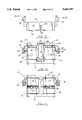
- FIG. 4is a perspective exploded view of the preferred embodiment of the apparatus of the present invention.
- FIG. 5is a partial perspective exploded view of the preferred embodiment of the apparatus of the present invention.
- FIG. 6is a partial end view of the preferred embodiment of the apparatus of the present invention.
- FIG. 7is a partial side view of the preferred embodiment of the apparatus of the present invention.
- FIG. 8is a partial perspective view of the preferred embodiment of the apparatus of the present invention.
- FIG. 9is a partial end view of the preferred embodiment of the apparatus of the present invention.
- FIG. 10is a partial top view of the preferred embodiment of the apparatus of the present invention.
- FIG. 11is partial bottom view of the preferred embodiment of the apparatus of the present invention.
- FIG. 13is a fragmentary view of the sleeve component of the valgus module portion of the preferred embodiment of the apparatus of the present invention.
- FIG. 14is an end fragmentary view of the valgus sleeve component of the module portion of the preferred embodiment of the apparatus of the present invention.
- FIG. 15is a side fragmentary view of the sleeve component of the valgus module portion of the preferred embodiment of the apparatus of the present invention.
- FIG. 18is a rear view of the posterior referencing paddles of the preferred embodiment of the apparatus of the present invention.
- FIG. 19is a bottom fragmentary view illustrating the posterior referencing paddles of the preferred embodiment of the apparatus of the present invention.
- FIG. 20is fragmentary perspective view illustrating the posterior referencing paddles of the preferred embodiment of the apparatus of the present invention.
- FIG. 22is a side fragmentary view of the distal cutting block portion of the preferred embodiment of the apparatus of the present invention.
- FIG. 24is an end fragmentary view of the distal cutting block of the preferred embodiment of the apparatus of the present invention.
- FIG. 25is another end fragmentary view of the distal cutting block of the preferred embodiment of the apparatus of the present invention.
- FIG. 26is a top fragmentary view illustrating the distal cutting block portion of the preferred embodiment of the apparatus of the present invention.
- FIGS. 27-28are perspective views schematically illustrating the placement of cuts on the patient s distal femur as part of the method and apparatus of the present invention
- FIGS. 29-30are perspective views of the patient s distal femur showing placement of the femoral prostheses trials thereon;
- FIG. 31is a perspective view of the preferred embodiment of the apparatus of the present invention illustrating a posterior referencing technique
- FIG. 32is a perspective view illustrating the patient s femur after surgical cuts have been made including anterior, posterior, distal and chamfer cuts;
- FIGS. 33-34are perspective views of the femoral prosthesis trial portion of the preferred embodiment of the apparatus of the present invention.
- FIG. 1illustrates femoral preparation as the first part of the method of the present invention.
- the patient s knee joint 1is flexed and positioned for surgery.
- the femur 2 and distal femur 3are shown above the patient s tibia 4 and proximal tibia 5.
- the femoral intramedullary canal 8is drilled to accept an intramedullary reamer rod 35.
- the reamer rod 35(for example eight millimeter diameter) is slowly inserted into the patient s femoral shaft or intramedullary canal 8.
- the patient s femuris sized with a femoral sizer 9.
- a femoral sizer 9is placed on the patient s distal femur 3 and over the reamer rod 35.
- Femoral sizersare commercially available and known in the art. The proper size prosthesis is determined by reading a scale on the femoral sizers. The femoral sizer 9 is removed leaving the reamer rod 35 in place within the patient s femoral intramedullary canal 8.
- the apparatus 10 of the present inventioncan be selectively used with either anterior or posterior referencing. If the surgeon wishes to use an anterior referencing technique, the feeler gauge 65 of FIGS. 3A, 4, and 5 is used.
- FIG. 3Ashows anterior referencing.
- feeler gauge 65(and not the posterior referencing paddle 90) is affixed to block 11.
- the posterior referencing paddle 90 of FIGS. 16-21 and 31(and not feeler gauge 65) is affixed to cutting block 11.
- the paddle 90is affixed to block 11, the paddle flanges 91, 92 placed against the patient s posterior condylar surfaces and then the valgus module 30 is tightened.
- FIGS. 3 and 3Athe femoral cutting block is designated generally by the numeral 10.
- FIGS. 4-21illustrate with more detail the preferred embodiment of the apparatus of the present invention designated in FIG. 4 generally by the numeral 10.
- Femoral cutting instrument 10includes a cutting block 11 body having an upper planar surface 12 and a lower planar surface 13.
- Cutting block 11also provides an anterior surface 14 and a posterior surface 15.
- Cutting block body 11includes side walls 16, 17.
- An internal, anterior posterior (A/P) slot 18extends between anterior surface 14 and posterior surface 15. In the preferred embodiment, the slot 18 does not completely, extend to surfaces 14, 15. Slot 18 accepts valgus module 30 during use. Valgus module 30 has a cylindrical member 50 that slides in slot 18, being movable along a path (axis 40) that extends generally between surfaces 14, 15 and parallel to sides 16, 17. The slot 18 has curved sidewalls 18C that fit closely to the curved contour of cylindrical member 50. Further, the slot 18 has a thickness D at surfaces 18A, 18B and at surface 13 that is smaller than the diameter of cylindrical member 50. Therefor, member 50 can only be removed from slot 18 at the open end of slot 18 (see FIG. 6) at surface 15.
- the valgus module 30can be adjusted into several positions relative to the block 11 by sliding the module to the desired location on the block 11. Module 30 provides this adjustability relative to block 11 when the module 30 is referenced upon an intramedullary rod or reamer 35, and prior to attachment of cutting block body 11 to the patient s distal femur 3. Block 11 is affixed to reamer 35 by placing the rod through open ended bore 49 of valgus module 30.
- the cutting block 11can then be firmly affixed to the patient s distal femur using bone spikes 27.
- a bone spike 27can be placed through either of the spike supports 28, 29 each spike support 28, 29 providing openings 31-34, as shown in the drawings.
- the surgeoncan rigidly lock the valgus module 30 to cutting block 11 by tightening knurled knob 36. The surgeon can then make a number of cuts in the patient s distal femur 3 as part of the surgical procedure of implanting a knee prosthesis.
- Cutting block 11provides a pair of anterior cutting guide slots 19, 20 on opposite sides of anterior-posterior slot 18. Slots 19, 20 are parallel to surface 14 and form a right (90°) angle with axis 40 of slot 18. Cutting block 11 provides a pair of posterior cutting guide slots 21, 22 on opposite sides of anterior-posterior slot 18. Slots 19, 20 are parallel to slots 19, 20 and to surface 14. Cutting block 11 provides a pair of co-planar anterior chamfer cutting guide slots 23, 24 and a pair of co-planar posterior chamfer cutting guide slots 25, 26.
- the aforementioned cutting guide slots 19-26allow the surgeon to make anterior and posterior cuts, and chamfer cuts for receiving a femoral prosthesis. These cuts shape the patient s distal femur 3 to receive a femoral prosthesis.
- the aforedescribed cutshave been formed by the surgeon including anterior cut 41, posterior cut 42, anterior chamfer cut 43, and posterior chamfer cut 44, and distal cut 45. This distal cut 45 is made using a distal cutting block (FIGS. 22-26) as will be described hereinafter.
- Block 11has openings 37, 38 that receive pegs of a posterior referencing paddle 90 (FIGS. 16-21) if posterior referencing is selected by the surgeon.
- An internally threaded opening 39 in block 11 anterior surface 14receives a threaded portion 74 of feeler gauge 65 if anterior referencing is selected.
- FIGS. 4 and 5illustrate the feeler gauge 65 portion of the preferred embodiment of the apparatus of the present invention 10.
- the feeler gauge 65is used with an anterior referencing technique because the surgeon uses the feeler gauge 65 to reference the patient s anterior cortical bone tissue. This is done by first affixing the cutting block 11 in a desired position on the patient s distal femur 3, mounting the cutting block 11 on reamer 35. The knob 36 is loosened. The bolt 72 is also loosened. Once the surgeon picks the proper location for the pointer arm 67 of feeler gauge 65, the feeler gauge 68 is then tightened by tightening the nut 72 against the threaded member 74. Now the proper location of block 11 has been determined and the valgus module 30 is tightened using knob 36.
- the valgus module 30Upon tightening, the valgus module 30 forms an acute angle between the central longitudinal axis of reamer 35 and the parallel, opposed flat surfaces 12, 13 of block 11.
- the block 11 peripheral sides 14-18are at right angles to each adjoining side and are also at right angles to the parallel flat surfaces 12, 13.
- the feeler gauge 65includes a support block 66 that receives pointer arm 67.
- Pointer arm 67includes a pointer 68 that contacts that patient s anterior cortical bone tissue during anterior referencing.
- a longitudinal slot 69 in pointer arm 67allows bolt 72 to pass therethrough and form a connection with internally threaded opening 39.
- a peripheral shoulder 70surrounds longitudinal slot 69.
- a flat surface 71extends between longitudinal slot 69 and peripheral shoulder 70.
- the area of flat surface 71 and peripheral shoulder 70receive plate 73 having an opening 79 therethrough.
- the plate 79provides a bearing member for interfacing between bolt 72 and pointer arm 67.
- the bolt 72is threadably engaged in threaded opening 39 of block 11.
- Retaining ring 76insures that all pieces of 65 do not come apart once assembled.
- Bolt 72extends through opening 84 of support block 66, longitudinal slot 69 of arm 67, and opening 79 of plate 73. When the user tightens the nut 72, the plate 73 bears against the surface 71 of arm 67 and locks the arm 67 against support block 66.
- Support block 66includes a rectangular slot 80 that is configured to receive arm 67.
- Block 66includes flat surface 81 and flat side walls 82, 83 that cradle arm 67.
- a transverse shoulder 85extends along the flat under side 88 of support block 66. Upon assembly of feeler gauge 65 to block 11, the transverse shoulder 85 aligns with and fits the intersection of block 11 surfaces 13, 14.
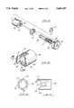
- FIGS. 4 and 12-15show the valgus module 30 in more detail.
- the module 30is comprised of a cylindrically shaped member 46 that includes smooth cylindrical unthreaded sections 48 and a cylindrical externally threaded section 47.
- the smooth sections 48are included on opposite sides of threaded section 47.
- the valgus module 30includes a bushing or sleeve 55, a washer 54, a hollow sleeve 46, and a cylindrically-shaped member 50 (see FIG. 4).
- the hollow sleeve 46includes a pair of spaced apart unthreaded sections 48 of small diameter with an externally threaded section 47 therebetween.
- Annular groove 52is positioned at smooth section 48 between knob 36 and threaded section 47.
- the annular grooveaccepts lock ring 53.
- the hollow sleeve 46extends through washer 54 and through the opening 58 of bushing 55.
- Bushing 55has an open cylindrically-shaped center portion 56.
- One end of the bushing 55is provided with an annular shoulder 57 so that opening 58 is smaller than the opened cylindrically-shaped center 56.
- a pair of appendages 61, 63are provided at the end portion of bushing opposite annular shoulder 57.
- the appendages 61, 63each provide a lower flat foot 62, 64. These flat surfaces 62, 64 bear against the flat surfaces 18A, 18B that extend longitudinally on each side of slot 18.
- the appendage 61is longer than the appendage 63 and the surfaces 62, 64 are angled (as shown in FIG. 15) with respect to flat annular shoulder 57 and bore 49. This produces an angulation when the surfaces 62, 64 rest against the surfaces 18A, 18B.
- the apparatus 10 of the present inventionis reversible for the left/right leg of the patient. The surgeon can simply rotate the bushing 55 so that the longer appendage 62 bears against the selected surface 18A or 18B depending upon which knee of the patient is being implanted with a knee prosthesis.
- a pair of slots 59, 60 in bushing 55accept lock pin 86 that is implanted in opening 87 of cylindrical member 50.
- the combination of lock pin 86 and the slots 59, 60prevent rotation of bushing 55 relative to block 11 during use.
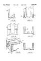
- FIGS. 16-21show a posterior paddle 90 that can be used for posterior referencing.
- Paddle 90includes a pair of spaced apart flanges 91, 92 that engage the posterior condyles of the patient s femur during referencing. There can be a space 93 between the flanges 91, 92.
- a pair of spaced apart pegs 94, 95fit the corresponding openings 37, 38 in cutting block 11. It should be understood that when the paddle assembly is used in combination with block 11, the anterior referencing feeler gauge 65 is not used. This allows the surgeon if so desired to use a posterior referencing technique.
- a base member 96extends between the flanges 91, 92 and the posts 94, 95. The base 96 provides a flat surface 97 that registers tightly against flat surface 12 of cutting block 11.
- the base 96can include a pair of appendages 98, 99 with a space 100 therebetween.
- FIGS. 22-26show a distal cutting block 101 that is used for cutting the patient s distal femur after the anterior and posterior cuts 41, 42 have been made and after the anterior and posterior chamfer cuts 43, 44 have been made using block 11.
- the distal block 101is affixed using set screws 102, 103 to cutting block 11, and more particularly to the anterior 14 surface thereof, as shown in FIG. 28.
- the block 101provides a pair of spaced apart slots 104, 105 that is used to guide a cutting instrument C during a cutting of the distal femur as shown in FIG. 28.
- the block 101provides a flat surface 106 that fits closely against the anterior surface 14 of cutting block 11.
- a pair of spaced apart flanges 107, 108register respectively against the surfaces 13 and 12.
- Each of the set screwscan have a conically-shaped end portion 109 that can fit in a groove defined by the chamfer cuts 25, 26 at surface 12 at block 11.
- the surgeonsimply mounts the cutting block 101 on the anterior 14 surface of block 11 and tightens the set screws 102, 103 and until the conical portion 109 engages surface 12 of block 11. This forces the flange 108 into tight engagement with the flat surface 13 of cutting block 11.
- the slots 104, 105are spaced away from surface 13 so that the surgeon can pass the cutting saw C through the slots 104, 105 and to cut the distal femur as shown in FIG. 28.
- FIGS. 33, 34 and 29-30illustrate the use of a trial prosthesis designated generally by the numeral 110.
- the trial prosthesis 110has a generally J-shaped articulating surface 111 and a non-articulating surface 112 that has five surfaces that correspond to the cuts 41-45 made on the patient s distal femur as shown in FIG. 32.
- An insert 113is removably mounted to the center of trial prosthesis 110.
- a pair of flat cutting guide surfaces 114, 115are exposed.
- the surfaces 114, 115intersect each other to form an angle of between 0 and 180 degrees.
- the surgeoncan then use a cutting instrument C resect the patello femoral groove by forming two (2) cuts, registering flat blade B against cutting guide surfaces 114, 115 as shown in FIG. 29.
- the resulting V shaped notch 116accommodates a projection on the posterior surface of the final femoral prosthesis component.
Landscapes
- Health & Medical Sciences (AREA)
- Surgery (AREA)
- Life Sciences & Earth Sciences (AREA)
- Biomedical Technology (AREA)
- Medical Informatics (AREA)
- Oral & Maxillofacial Surgery (AREA)
- Nuclear Medicine, Radiotherapy & Molecular Imaging (AREA)
- Transplantation (AREA)
- Physical Education & Sports Medicine (AREA)
- Engineering & Computer Science (AREA)
- Orthopedic Medicine & Surgery (AREA)
- Heart & Thoracic Surgery (AREA)
- Dentistry (AREA)
- Molecular Biology (AREA)
- Animal Behavior & Ethology (AREA)
- General Health & Medical Sciences (AREA)
- Public Health (AREA)
- Veterinary Medicine (AREA)
- Surgical Instruments (AREA)
- Media Introduction/Drainage Providing Device (AREA)
- Prostheses (AREA)
- Accommodation For Nursing Or Treatment Tables (AREA)
Abstract
Description
______________________________________ PARTS LIST Part Number Description ______________________________________ 1 knee joint 2 femur 3 distal femur 4 tibia 5 proximal tibia 6 drill bit 7 drill motor 8 intramedullary canal 9 femoral sizer 10 femoral cutting block 11 cutting block 12 upper planar surface 13 lower planar surface 14 anterior surface 15 posterior surface 16 side wall 17 side wall 18 internal A/P slot 19 anterior cutting guide slot 20 anterior cutting guide slot 21 posterior cutting guide slot 22 posterior cutting guide slot 23 anterior chamfer cutting guide slot 24 anterior chamfer cutting guide slot 25 posterior chamfer cutting guide slot 26 posterior chamfer cutting guide slot 27 bone spike 28 spike support 29 spike support 30 valgus module 31 opening 32 opening 33 opening 34 opening 35 intramedullary rod 36 knurled knob 37 opening 38 opening 39 threaded hole 40 axis 41 cut 42 cut 43 cut 44 cut 45 cut 46 sleeve 47 threaded portion 48 unthreaded portion 49 open ended bore 50 bushing 51 internally threaded bore 52 annular groove 53 lock ring 54 washer 55 sleeve 56 open center 57 annular shoulder 58 opening 59 slot 60 slot 61 appendage 62 flat surface 63 appendage 64 flat surface 65 feeler gauge 66 support block 67 pointer arm 68 pointer 69 longitudinal slot 70 peripheral shoulder 71 flat surface 72 bolt 73 plate 74 threaded section 75 annular groove 76 retaining ring 79 opening 80 rectangular slot 81 flat surface 82 side wall 83 side wall 84 opening 85 transverse shoulder 86 lock pin 87 opening 88 flat underside 90 posterior referencing paddle 91 flange 92 flange 93 gap 94 post 95 post 96 base 97 flat surface 98 appendage 99 appendage 100 space 101 distal cutting block 102 set screw 103 set screw 104 slot 105 slot 106 flat surface 107 flange 108 flange 109 cone-shaped end 110 trial prosthesis 111 articulating surface 112 non-articulating surface 113 insert 114 cutting guide surface 115 cutting guide surface 116 V-shaped recess B cutting blade C cutting instrument D slot thickness ______________________________________
Claims (16)
Priority Applications (13)
| Application Number | Priority Date | Filing Date | Title |
|---|---|---|---|
| US08/389,099US5683397A (en) | 1995-02-15 | 1995-02-15 | Distal femoral cutting guide apparatus for use in knee joint replacement surgery |
| AT96906388TATE342694T1 (en) | 1995-02-15 | 1996-02-13 | GUIDE TO CUTTING THE KNEE SURFACE |
| JP8525068AJPH11504532A (en) | 1995-02-15 | 1996-02-13 | Distal femoral cutting guide |
| DE69636636TDE69636636T2 (en) | 1995-02-15 | 1996-02-13 | Guide for cutting the kneecracle surface |
| CN96193281ACN1181696A (en) | 1995-02-15 | 1996-02-13 | Distal femoral cutting guide |
| AU49780/96AAU696251B2 (en) | 1995-02-15 | 1996-02-13 | Distal femoral cutting guide |
| KR1019970705645AKR19980702248A (en) | 1995-02-15 | 1996-02-13 | Distal Femoral Cut Guide |
| EP96906388AEP0809471B1 (en) | 1995-02-15 | 1996-02-13 | Distal femoral cutting guide |
| PCT/US1996/001889WO1996025114A1 (en) | 1995-02-15 | 1996-02-13 | Distal femoral cutting guide |
| PT96906388TPT809471E (en) | 1995-02-15 | 1996-02-13 | Distal femoral cutting guide |
| DK96906388TDK0809471T3 (en) | 1995-02-15 | 1996-02-13 | Distal femoral cutting guide |
| ES96906388TES2275272T3 (en) | 1995-02-15 | 1996-02-13 | DISTAL FEMORAL COURT GUIDE. |
| CA002211574ACA2211574A1 (en) | 1995-02-15 | 1996-02-13 | Distal femoral cutting guide |
Applications Claiming Priority (1)
| Application Number | Priority Date | Filing Date | Title |
|---|---|---|---|
| US08/389,099US5683397A (en) | 1995-02-15 | 1995-02-15 | Distal femoral cutting guide apparatus for use in knee joint replacement surgery |
Publications (1)
| Publication Number | Publication Date |
|---|---|
| US5683397Atrue US5683397A (en) | 1997-11-04 |
Family
ID=23536806
Family Applications (1)
| Application Number | Title | Priority Date | Filing Date |
|---|---|---|---|
| US08/389,099Expired - LifetimeUS5683397A (en) | 1995-02-15 | 1995-02-15 | Distal femoral cutting guide apparatus for use in knee joint replacement surgery |
Country Status (13)
| Country | Link |
|---|---|
| US (1) | US5683397A (en) |
| EP (1) | EP0809471B1 (en) |
| JP (1) | JPH11504532A (en) |
| KR (1) | KR19980702248A (en) |
| CN (1) | CN1181696A (en) |
| AT (1) | ATE342694T1 (en) |
| AU (1) | AU696251B2 (en) |
| CA (1) | CA2211574A1 (en) |
| DE (1) | DE69636636T2 (en) |
| DK (1) | DK0809471T3 (en) |
| ES (1) | ES2275272T3 (en) |
| PT (1) | PT809471E (en) |
| WO (1) | WO1996025114A1 (en) |
Cited By (143)
| Publication number | Priority date | Publication date | Assignee | Title |
|---|---|---|---|---|
| USD400942S (en) | 1997-05-08 | 1998-11-10 | Billings David P | Oversized mallet putter head |
| WO1999009900A1 (en)* | 1997-08-25 | 1999-03-04 | Depuy Orthopaedics, Inc. | Low friction saw slot |
| US5897559A (en)* | 1995-11-02 | 1999-04-27 | Medidea, Llc | Bone cutting guides for use in the implantation of prosthetic joint components |
| EP0947169A3 (en)* | 1998-03-28 | 1999-11-03 | Howmedica Inc. | Methods and tools for femoral intermedullary revision surgery |
| US6007537A (en)* | 1998-06-15 | 1999-12-28 | Sulzer Orthopedics Inc. | Nested cutting block |
| EP1032319A4 (en)* | 1997-11-18 | 2002-03-20 | Michael J Pappas | Anterior-posterior femoral resection guide with set of detachable collets |
| US20030093079A1 (en)* | 1997-09-18 | 2003-05-15 | Masini Michael A. | Joint replacement methods and apparatus |
| US20030163137A1 (en)* | 2002-02-26 | 2003-08-28 | Smucker Donald M. | Patella resection guide |
| US20030171757A1 (en)* | 2002-03-05 | 2003-09-11 | Coon Thomas M. | Minimally invasive total knee arthroplasty method and instrumentation |
| US20030181918A1 (en)* | 2002-02-11 | 2003-09-25 | Crista Smothers | Image-guided fracture reduction |
| US6629978B2 (en)* | 2001-04-23 | 2003-10-07 | Howmedica Osteonics Corp. | Valgus adapter |
| FR2838626A1 (en)* | 2002-04-19 | 2003-10-24 | Cabinet Boettcher | Sawing jig for femur condyle parts comprises miter box with parallel orifices for receiving positioning pins previously implanted in femur |
| US20030236521A1 (en)* | 2002-06-21 | 2003-12-25 | Scott Brown | Prosthesis cutting guide, cutting tool and method |
| US20040078042A1 (en)* | 1997-09-18 | 2004-04-22 | Masini Michael A. | Bone-conserving orthopedic instrumentation and appliances |
| US6758850B2 (en) | 2002-03-29 | 2004-07-06 | Depuy Orthopaedics, Inc. | Instruments and methods for flexion gap adjustment |
| GB2397526A (en)* | 2003-01-22 | 2004-07-28 | Biomet Merck Ltd | Bone jig with adjustment means |
| US6770077B2 (en) | 2001-05-21 | 2004-08-03 | Nemco Medical, Ltd. | Femoral knee saw guide and method |
| US20040153086A1 (en)* | 2003-02-04 | 2004-08-05 | Sanford Adam H. | Provisional orthopedic implant and recutting instrument guide |
| US20040153084A1 (en)* | 2003-01-31 | 2004-08-05 | Haney Mark D. | Resection guide alignment apparatus |
| US6780190B2 (en)* | 2001-01-23 | 2004-08-24 | Depuy Orthopaedics, Inc. | Method and apparatus for resecting a greater tubercle from a humerus of a patient during performance of a shoulder replacement procedure |
| US20040249387A1 (en)* | 2003-04-25 | 2004-12-09 | Francisco Faoro | Apparatus for the preparation of a femoral condyle |
| US20050021037A1 (en)* | 2003-05-29 | 2005-01-27 | Mccombs Daniel L. | Image-guided navigated precision reamers |
| US20050049603A1 (en)* | 2002-07-23 | 2005-03-03 | Ortho Development Corporation | Knee balancing block |
| US20050059980A1 (en)* | 2003-09-15 | 2005-03-17 | Centerpulse Orthopedics Ltd. | Adjustment apparatus |
| US20050171548A1 (en)* | 2003-11-18 | 2005-08-04 | Kelman David C. | Surgical technique and instrumentation for minimal incision hip arthroplasty surgery |
| US20050240195A1 (en)* | 2004-04-22 | 2005-10-27 | Howmedica Osteonics Corp. | Bone shaped cutting block |
| US20050240196A1 (en)* | 2004-03-09 | 2005-10-27 | Davis Kenneth P | Apparatus for use in orthopaedic surgery |
| US20050267484A1 (en)* | 2005-08-18 | 2005-12-01 | Jeff Menzner | Extended trochanteric osteotomy guide |
| US20060036257A1 (en)* | 2004-08-06 | 2006-02-16 | Zimmer Technology, Inc. | Tibial spacer blocks and femoral cutting guide |
| US20060058806A1 (en)* | 2004-08-31 | 2006-03-16 | Howmedica Osteonics Corp. | Modular capture with magnetic attachment |
| US20060142778A1 (en)* | 2004-12-21 | 2006-06-29 | Dees Roger R Jr | Rotational alignment femoral sizing guide |
| US20060149276A1 (en)* | 2002-12-20 | 2006-07-06 | Grimm James E | Surgical instrument and positioning method |
| US20060173463A1 (en)* | 2004-12-21 | 2006-08-03 | Dees Roger R Jr | Distal femoral trial with removable cutting guide |
| US20060179979A1 (en)* | 2005-02-01 | 2006-08-17 | Dees Roger R Jr | Lockable orientation stylus |
| US20060200161A1 (en)* | 2003-06-18 | 2006-09-07 | Perception Raisonnement Action En Medecine | Guiding device for bone cutting |
| US7104996B2 (en) | 2000-01-14 | 2006-09-12 | Marctec. Llc | Method of performing surgery |
| US20060217734A1 (en)* | 2005-03-09 | 2006-09-28 | Zimmer Technology, Inc. | Femoral resection guide apparatus and method |
| US20060241635A1 (en)* | 2005-04-06 | 2006-10-26 | Stumpo David J | Prosthetic revision knee system |
| US20060247647A1 (en)* | 2002-11-27 | 2006-11-02 | Zimmer Technology, Inc. | Method and apparatus for achieving correct limb alignment in unicondylar knee arthroplasty |
| US20070118139A1 (en)* | 2005-10-14 | 2007-05-24 | Cuellar Alberto D | System and method for bone resection |
| US20070173848A1 (en)* | 2004-07-27 | 2007-07-26 | Biomet Uk Limited | Bone jig |
| US20070213738A1 (en)* | 2006-03-09 | 2007-09-13 | Martin Jeffrey W | Instruments for Total Knee Arthroplasty |
| US20070270872A1 (en)* | 2006-05-19 | 2007-11-22 | Gary Thau | Bone cutting fixture assembly with guide appendages |
| US20080015608A1 (en)* | 2004-11-26 | 2008-01-17 | Callum Colquhoun | Burr guide assembly |
| US20080097450A1 (en)* | 2006-09-14 | 2008-04-24 | Zimmer Technology, Inc. | Patella clamp |
| US20080172056A1 (en)* | 2007-01-17 | 2008-07-17 | Edwards Scott G | System and method for bone shortening |
| US20080306485A1 (en)* | 2002-05-24 | 2008-12-11 | Zimmer Technology, Inc. | Instruments for knee surgery and method uf use |
| US20080306484A1 (en)* | 2003-02-03 | 2008-12-11 | Zimmer, Inc. | Apparatus for knee surgery and method of use |
| US7477926B2 (en) | 2004-03-31 | 2009-01-13 | Smith & Nephew, Inc. | Methods and apparatuses for providing a reference array input device |
| US7510557B1 (en) | 2000-01-14 | 2009-03-31 | Bonutti Research Inc. | Cutting guide |
| US20090088760A1 (en)* | 2007-09-30 | 2009-04-02 | Aram Luke J | Customized Patient-Specific Bone Cutting Instrumentation |
| US20090088762A1 (en)* | 2007-09-30 | 2009-04-02 | Koenemann Jeffery L | Modular femoral orthopaedic surgical instrument |
| US7520880B2 (en) | 2006-01-09 | 2009-04-21 | Zimmer Technology, Inc. | Adjustable surgical support base with integral hinge |
| US20090105837A1 (en)* | 2005-06-03 | 2009-04-23 | Lafosse Laurent | Instrument for use in a joint replacement procedure |
| US20090132045A1 (en)* | 2005-06-03 | 2009-05-21 | Lafosse Laurent | Instrument for use in a joint replacement procedure |
| US7547307B2 (en) | 2001-02-27 | 2009-06-16 | Smith & Nephew, Inc. | Computer assisted knee arthroplasty instrumentation, systems, and processes |
| US7572262B1 (en)* | 2005-06-07 | 2009-08-11 | Biomet Manufacturing Corp. | Femoral guide for revision surgery |
| US20090222010A1 (en)* | 2005-06-03 | 2009-09-03 | Lafosse Laurent | Instrument for use in a joint replacement procedure |
| US20090312780A1 (en)* | 2006-07-20 | 2009-12-17 | Turner Nicholas Nmi | Medical device |
| US20090326544A1 (en)* | 2008-06-27 | 2009-12-31 | Ryan Chessar | Knee ligament balancer |
| US7641660B2 (en)* | 2004-03-08 | 2010-01-05 | Biomet Manufacturing Corporation | Method, apparatus, and system for image guided bone cutting |
| US7641661B2 (en) | 2003-12-26 | 2010-01-05 | Zimmer Technology, Inc. | Adjustable resection guide |
| US20100036444A1 (en)* | 2008-08-01 | 2010-02-11 | Lisa Major | Orthopaedic surgical method for performing a patellofemoral arthroplasty procedure |
| US20100057088A1 (en)* | 2008-08-26 | 2010-03-04 | Maxx Orthopedics, Inc. | Distal Femoral Cutting Guide |
| US7708741B1 (en) | 2001-08-28 | 2010-05-04 | Marctec, Llc | Method of preparing bones for knee replacement surgery |
| US20100121331A1 (en)* | 2003-11-18 | 2010-05-13 | Sharp Jeffrey A | Universal double offset surgical instrument |
| US20100130986A1 (en)* | 2008-11-11 | 2010-05-27 | Perception Raisonnement Action En Medecine | Surgical robotic system |
| US20100131021A1 (en)* | 2006-11-15 | 2010-05-27 | Depuy International Limited | Locating a bone axis |
| US7744600B2 (en) | 2006-01-10 | 2010-06-29 | Zimmer Technology, Inc. | Bone resection guide and method |
| US7764985B2 (en) | 2003-10-20 | 2010-07-27 | Smith & Nephew, Inc. | Surgical navigation system component fault interfaces and related processes |
| US7780671B2 (en) | 2006-01-23 | 2010-08-24 | Zimmer Technology, Inc. | Bone resection apparatus and method for knee surgery |
| US7794467B2 (en) | 2003-11-14 | 2010-09-14 | Smith & Nephew, Inc. | Adjustable surgical cutting systems |
| US20100234850A1 (en)* | 2005-02-01 | 2010-09-16 | Smith And Nephew, Inc. | Lockable Orientation Instrument Assembly |
| US20100262150A1 (en)* | 2009-04-13 | 2010-10-14 | George John Lian | Custom radiographically designed cutting guides and instruments for use in total ankle replacement surgery |
| US7862570B2 (en) | 2003-10-03 | 2011-01-04 | Smith & Nephew, Inc. | Surgical positioners |
| US7935118B2 (en)* | 2002-06-21 | 2011-05-03 | Depuy Products, Inc. | Prosthesis removal cutting guide, cutting tool and method |
| US20110112542A1 (en)* | 2009-11-10 | 2011-05-12 | Wright Medical Technology, Inc. | Adjustable revision guide |
| US20110130761A1 (en)* | 2005-04-07 | 2011-06-02 | Perception Raisonnement Action En Medecine | Robotic guide assembly for use in computer-aided surgery |
| US7959635B1 (en) | 2000-01-14 | 2011-06-14 | Marctec, Llc. | Limited incision total joint replacement methods |
| US20110160735A1 (en)* | 2008-09-10 | 2011-06-30 | Depuy International Limited | Surgical resection guide |
| US7993341B2 (en) | 2004-03-08 | 2011-08-09 | Zimmer Technology, Inc. | Navigated orthopaedic guide and method |
| US8105385B2 (en) | 2001-01-23 | 2012-01-31 | Depuy Products, Inc. | Procedure for the treatment of cuff tear arthropathy |
| US8109942B2 (en) | 2004-04-21 | 2012-02-07 | Smith & Nephew, Inc. | Computer-aided methods, systems, and apparatuses for shoulder arthroplasty |
| US8114086B2 (en) | 2004-03-08 | 2012-02-14 | Zimmer Technology, Inc. | Navigated cut guide locator |
| US8177788B2 (en) | 2005-02-22 | 2012-05-15 | Smith & Nephew, Inc. | In-line milling system |
| US8265949B2 (en) | 2007-09-27 | 2012-09-11 | Depuy Products, Inc. | Customized patient surgical plan |
| US8357111B2 (en) | 2007-09-30 | 2013-01-22 | Depuy Products, Inc. | Method and system for designing patient-specific orthopaedic surgical instruments |
| US8491596B2 (en) | 2002-06-21 | 2013-07-23 | Depuy Products, Inc. | Method for removal of bone |
| US8551023B2 (en) | 2009-03-31 | 2013-10-08 | Depuy (Ireland) | Device and method for determining force of a knee joint |
| US8556830B2 (en) | 2009-03-31 | 2013-10-15 | Depuy | Device and method for displaying joint force data |
| US8597210B2 (en) | 2009-03-31 | 2013-12-03 | Depuy (Ireland) | System and method for displaying joint force data |
| US20130325017A1 (en)* | 2012-05-29 | 2013-12-05 | Zimmer, Inc. | Surgical cutting guide and method |
| US20130325045A1 (en)* | 2012-06-04 | 2013-12-05 | Depuy International Limited | Surgical cutting guide |
| US8641721B2 (en) | 2011-06-30 | 2014-02-04 | DePuy Synthes Products, LLC | Customized patient-specific orthopaedic pin guides |
| US8721568B2 (en) | 2009-03-31 | 2014-05-13 | Depuy (Ireland) | Method for performing an orthopaedic surgical procedure |
| US8740985B1 (en) | 2012-11-30 | 2014-06-03 | Smith & Nephew, Inc. | Knee prosthesis |
| US8740817B2 (en) | 2009-03-31 | 2014-06-03 | Depuy (Ireland) | Device and method for determining forces of a patient's joint |
| US8747410B2 (en) | 2010-10-26 | 2014-06-10 | Zimmer, Inc. | Patellar resection instrument with variable depth guide |
| US20140257305A1 (en)* | 2013-03-05 | 2014-09-11 | Jon M. Edwards | Polymer 4-in-1 femoral cutting block |
| US8834486B2 (en) | 2003-12-08 | 2014-09-16 | Biomet Manufacturing, Llc | Femoral guide for implanting a femoral knee prosthesis |
| US8900316B2 (en) | 2010-01-29 | 2014-12-02 | Smith & Nephew, Inc. | Cruciate-retaining knee prosthesis |
| US8974459B1 (en) | 2010-05-21 | 2015-03-10 | Howmedica Osteonics Corp. | Natural alignment knee instruments |
| US8979855B2 (en) | 2007-09-30 | 2015-03-17 | DePuy Synthes Products, Inc. | Customized patient-specific bone cutting blocks |
| US8979847B2 (en) | 2011-06-06 | 2015-03-17 | Biomet Manufacturing, Llc | Method and apparatus for implanting a knee prosthesis |
| US20150088142A1 (en)* | 2011-06-01 | 2015-03-26 | Smith & Nephew, Inc. | Patient specific instrument |
| US9089343B2 (en) | 2005-10-03 | 2015-07-28 | Smith & Nephew, Inc. | Locking instrument assembly |
| US9119734B2 (en) | 2006-10-31 | 2015-09-01 | Smith & Nephew, Inc. | Trial femoral prosthesis and its use |
| US9138239B2 (en) | 2007-09-30 | 2015-09-22 | DePuy Synthes Products, Inc. | Customized patient-specific tibial cutting blocks |
| US9173662B2 (en) | 2007-09-30 | 2015-11-03 | DePuy Synthes Products, Inc. | Customized patient-specific tibial cutting blocks |
| US9220510B2 (en) | 2011-06-15 | 2015-12-29 | Perception Raisonnement Action En Medecine | System and method for bone preparation for an implant |
| US9381011B2 (en) | 2012-03-29 | 2016-07-05 | Depuy (Ireland) | Orthopedic surgical instrument for knee surgery |
| US20170007273A1 (en)* | 2015-07-07 | 2017-01-12 | Zimmer, Inc. | Femoral finishing guide |
| US9545459B2 (en) | 2012-03-31 | 2017-01-17 | Depuy Ireland Unlimited Company | Container for surgical instruments and system including same |
| US20170056024A1 (en)* | 2012-04-18 | 2017-03-02 | Conformis, Inc | Tibial Guides, Tools, and Techniques for Resecting the Tibial Plateau |
| US9786022B2 (en) | 2007-09-30 | 2017-10-10 | DePuy Synthes Products, Inc. | Customized patient-specific bone cutting blocks |
| US9795392B2 (en) | 2012-02-06 | 2017-10-24 | Arthrex, Inc. | Surgical instrumentation set and surgical technique |
| US20170319216A1 (en)* | 2016-05-05 | 2017-11-09 | Adam I. Harris | Cutting block apparatus and method of total knee arthroplasty |
| US10070973B2 (en) | 2012-03-31 | 2018-09-11 | Depuy Ireland Unlimited Company | Orthopaedic sensor module and system for determining joint forces of a patient's knee joint |
| US10098761B2 (en) | 2012-03-31 | 2018-10-16 | DePuy Synthes Products, Inc. | System and method for validating an orthopaedic surgical plan |
| US10105242B2 (en) | 2011-09-07 | 2018-10-23 | Depuy Ireland Unlimited Company | Surgical instrument and method |
| US10111673B2 (en) | 2013-03-05 | 2018-10-30 | Depuy Ireland Unlimited Company | Polymer 4-in-1 femoral cutting block including metallic protective bushings |
| US10149722B2 (en) | 2010-02-25 | 2018-12-11 | DePuy Synthes Products, Inc. | Method of fabricating customized patient-specific bone cutting blocks |
| US10206792B2 (en) | 2012-03-31 | 2019-02-19 | Depuy Ireland Unlimited Company | Orthopaedic surgical system for determining joint forces of a patients knee joint |
| US10213320B2 (en) | 2011-05-17 | 2019-02-26 | Medacta International Sa | Surgical guide for implanting a knee prosthesis |
| US10299801B2 (en) | 2013-04-12 | 2019-05-28 | Depuy Ireland Unlimited Company | Distal femoral jig assembly |
| US10350087B2 (en) | 2013-03-18 | 2019-07-16 | Medacta International Sa | Set of instruments for the implantation of an acetabular prosthesis |
| US10357255B2 (en) | 2015-10-08 | 2019-07-23 | Howmedica Osteonics Corp. | Globalized total knee instrumentation |
| US10363147B2 (en)* | 2016-05-18 | 2019-07-30 | Depuy Ireland Unlimited Company | System and method for preparing a patient's femur in an orthopaedic joint replacement procedure |
| US10470898B2 (en) | 2016-05-18 | 2019-11-12 | Depuy Ireland Unlimited Company | Orthopaedic instrument system for surgically-preparing a patient's tibia |
| US10786293B2 (en) | 2016-05-06 | 2020-09-29 | Karl Leibinger Medizintechnik Gmbh & Co. Kg | Mandibular resection template |
| US10940024B2 (en) | 2017-07-26 | 2021-03-09 | Optimotion Implants LLC | Universal femoral trial system and methods |
| US11051829B2 (en) | 2018-06-26 | 2021-07-06 | DePuy Synthes Products, Inc. | Customized patient-specific orthopaedic surgical instrument |
| US20210322032A1 (en)* | 2020-04-16 | 2021-10-21 | Orthosoft Ulc | Devices and methods for posterior resection in robotically assisted partial knee arthroplasties |
| US11406502B2 (en) | 2017-03-02 | 2022-08-09 | Optimotion Implants LLC | Orthopedic implants and methods |
| US20220265354A1 (en)* | 2019-07-17 | 2022-08-25 | Mako Surgical Corp. | Surgical registration tools, systems, and methods of use in computer-assisted surgery |
| US11439409B2 (en) | 2019-09-18 | 2022-09-13 | Depuy Ireland Unlimited Company | Cutting block |
| US11666346B2 (en) | 2007-03-23 | 2023-06-06 | Xiros Limited | Surgical templates |
| USD1000614S1 (en)* | 2022-06-07 | 2023-10-03 | Virtamed Ag | Artificial knee prosthetics |
| DE102022205193A1 (en) | 2022-05-24 | 2023-11-30 | Aesculap Ag | Surgical instrument system |
| US12011371B2 (en) | 2016-05-18 | 2024-06-18 | Depuy Ireland Unlimited Company | System and method for surgically-preparing a patient's femur |
| US12076025B2 (en) | 2022-05-11 | 2024-09-03 | DePuy Synthes Products, Inc. | Polymer cutting block |
| US12083027B2 (en) | 2017-03-02 | 2024-09-10 | Optimotion Implants LLC | Universal femoral trial system and methods |
| US12376868B2 (en) | 2020-04-16 | 2025-08-05 | Orthosoft Ulc | Devices and methods for posterior resection in robotically assisted partial knee arthroplasties |
Families Citing this family (33)
| Publication number | Priority date | Publication date | Assignee | Title |
|---|---|---|---|---|
| US8083746B2 (en) | 2004-05-07 | 2011-12-27 | Arthrex, Inc. | Open wedge osteotomy system and surgical method |
| CN100471471C (en)* | 2004-05-07 | 2009-03-25 | I平衡医疗公司 | Open wedge osteotomy system and surgical method |
| US8496662B2 (en) | 2005-01-31 | 2013-07-30 | Arthrex, Inc. | Method and apparatus for forming a wedge-like opening in a bone for an open wedge osteotomy |
| US7967823B2 (en) | 2005-01-31 | 2011-06-28 | Arthrex, Inc. | Method and apparatus for performing an open wedge, high tibial osteotomy |
| CA2597228C (en) | 2005-02-09 | 2014-07-22 | Ibalance Medical, Inc. | Multi-part implant for open wedge knee osteotomies |
| CA2603400C (en) | 2005-04-01 | 2015-11-24 | Ibalance Medical, Inc. | Method and apparatus for performing an open wedge, high tibial osteotomy |
| CA2665393A1 (en)* | 2006-10-04 | 2008-04-10 | Smith & Nephew, Inc. | Device and method for distal resections of a knee prosthetic |
| US8409209B2 (en) | 2006-11-22 | 2013-04-02 | Arthrex, Inc. | Method and apparatus for performing an open wedge, high tibial osteotomy |
| US8187280B2 (en)* | 2007-10-10 | 2012-05-29 | Biomet Manufacturing Corp. | Knee joint prosthesis system and method for implantation |
| AU2008335328B2 (en) | 2007-12-06 | 2014-11-27 | Smith & Nephew, Inc. | Systems and methods for determining the mechanical axis of a femur |
| US8794977B2 (en) | 2009-04-29 | 2014-08-05 | Lifemodeler, Inc. | Implant training system |
| KR101973101B1 (en)* | 2009-05-29 | 2019-04-26 | 스미스 앤드 네퓨, 인크. | Methods and apparatus for performing knee arthroplasty |
| US9386994B2 (en) | 2010-06-11 | 2016-07-12 | Smith & Nephew, Inc. | Patient-matched instruments |
| WO2012001782A1 (en)* | 2010-06-30 | 2012-01-05 | Takei Tsunenori | Femoral condyle resection kit, femoral distal end face resection tool and femoral condyle posterior surface resection tool |
| CN103458804B (en) | 2010-08-16 | 2016-12-21 | 史密夫和内修有限公司 | Systems and methods for modifying the surface of bone |
| BR112013009069A2 (en)* | 2010-10-14 | 2016-07-19 | Smith & Nephew Inc | patient-attached instrumentation and methods |
| GB2489033B (en) | 2011-03-17 | 2016-05-25 | Biomet Uk Healthcare Ltd | Guide tool |
| WO2012173890A2 (en) | 2011-06-16 | 2012-12-20 | Smith & Nephew, Inc. | Surgical alignment using references |
| US9386998B2 (en) | 2011-10-27 | 2016-07-12 | Smith & Nephew, Inc. | Devices and methods for performing knee arthroplasty |
| US9050107B2 (en)* | 2012-05-30 | 2015-06-09 | Depuy (Ireland) | Method of surgically preparing a patient's femur |
| CN103006299A (en)* | 2012-12-12 | 2013-04-03 | 北京蒙太因医疗器械有限公司 | Adjustable osteotomy plate |
| JP6263690B2 (en)* | 2013-10-23 | 2018-01-24 | 国立大学法人信州大学 | Bone resection jig for knee replacement. |
| CN105310743B (en)* | 2014-07-09 | 2017-11-21 | 北京纳通科技集团有限公司 | A kind of osteotomy guider |
| CN104814770B (en)* | 2015-05-22 | 2017-10-27 | 北京爱康宜诚医疗器材股份有限公司 | Osteotomy positions instrument and femur osteotomy method |
| CN104825215B (en)* | 2015-05-22 | 2017-03-15 | 北京爱康宜诚医疗器材股份有限公司 | Osteotomy guide plate |
| EP3416567B1 (en)* | 2016-02-18 | 2021-03-31 | Michael Mason | Intramedullary based and omni-positionable cutting guide instrumentation for femoral epiphysis resection for knee prosthesis placement |
| DE102016108426A1 (en) | 2016-05-06 | 2017-11-09 | Karl Leibinger Medizintechnik Gmbh & Co. Kg | Fibula bone removal and disposal template |
| JP6272953B2 (en)* | 2016-06-22 | 2018-01-31 | スミス アンド ネフュー インコーポレイテッド | System and method for modifying bone surface |
| IT202000010393A1 (en)* | 2020-05-08 | 2021-11-08 | Rejoint S R L | 4-IN-1 CUTTING JIG FOR FEMORAL FINISHING |
| CN114515182A (en)* | 2020-11-20 | 2022-05-20 | 纳通生物科技(北京)有限公司 | A personalized knee joint bone surface positioning osteotomy navigation system and method |
| CN112754594B (en)* | 2021-01-21 | 2024-10-01 | 北京力达康科技有限公司 | Femoral condyle unilateral lead screw adjusting type osteotomy device |
| CN113367861B (en)* | 2021-06-21 | 2023-01-03 | 天衍医疗器材有限公司 | Probe lockable thighbone measurer |
| KR102652930B1 (en)* | 2023-11-27 | 2024-03-28 | 이수찬 | Surgical instrument to complement robotic artificial joint surgery |
Citations (26)
| Publication number | Priority date | Publication date | Assignee | Title |
|---|---|---|---|---|
| US4464729A (en)* | 1980-11-15 | 1984-08-07 | Itt Industries, Inc. | Binary MOS carry-look-ahead parallel adder |
| US4467801A (en)* | 1983-03-09 | 1984-08-28 | Wright Manufacturing Company | Method and apparatus for shaping a proximal tibial surface |
| US4474177A (en)* | 1983-03-09 | 1984-10-02 | Wright Manufacturing Company | Method and apparatus for shaping a distal femoral surface |
| EP0122669A1 (en)* | 1983-04-15 | 1984-10-24 | Pfizer Hospital Products Group, Inc. | Guide for femoral neck osteotomy |
| US4487203A (en)* | 1981-11-03 | 1984-12-11 | Androphy Gary W | Triplanar knee resection method |
| US4567886A (en)* | 1983-01-06 | 1986-02-04 | Petersen Thomas D | Flexion spacer guide for fitting a knee prosthesis |
| US4703751A (en)* | 1986-03-27 | 1987-11-03 | Pohl Kenneth P | Method and apparatus for resecting a distal femoral surface |
| US4721104A (en)* | 1985-12-02 | 1988-01-26 | Dow Corning Wright Corporation | Femoral surface shaping apparatus for posterior-stabilized knee implants |
| US4722330A (en)* | 1986-04-22 | 1988-02-02 | Dow Corning Wright Corporation | Femoral surface shaping guide for knee implants |
| US4736737A (en)* | 1986-03-31 | 1988-04-12 | William Fargie | Tibial cutting jig |
| US4738253A (en)* | 1981-12-31 | 1988-04-19 | Biomedical Engineering Trust | Guides for inclined surgical cuts or resections |
| US4738254A (en)* | 1981-12-31 | 1988-04-19 | Biomedical Engineering Trust | Positioner for surgical instruments |
| US4759350A (en)* | 1986-10-17 | 1988-07-26 | Dunn Harold K | Instruments for shaping distal femoral and proximal tibial surfaces |
| US4773407A (en)* | 1986-07-23 | 1988-09-27 | Thomas Petersen | Method and instruments for resection of the distal femur |
| EP0340176A2 (en)* | 1988-04-29 | 1989-11-02 | G. CREMASCOLI S.p.A. | Device for the resection of a femoral bone for the application of knee articulation prostheses |
| US4892093A (en)* | 1988-10-28 | 1990-01-09 | Osteonics Corp. | Femoral cutting guide |
| US4893619A (en)* | 1988-02-04 | 1990-01-16 | Intermedics Orthopedics, Inc. | Humeral osteotomy guide |
| US4907578A (en)* | 1986-07-23 | 1990-03-13 | Petersen Thomas D | Method and instruments for resection of the distal femur |
| US4935023A (en)* | 1989-01-09 | 1990-06-19 | Dow Corning Wright | Femoral surface shaping guide for knee implants |
| US4952213A (en)* | 1989-02-03 | 1990-08-28 | Boehringer Mannheim Corporation | Tibial cutting guide |
| US4959066A (en)* | 1989-02-24 | 1990-09-25 | Zimmer, Inc. | Femoral osteotomy guide assembly |
| US5002545A (en)* | 1989-01-30 | 1991-03-26 | Dow Corning Wright Corporation | Tibial surface shaping guide for knee implants |
| EP0466659A2 (en)* | 1990-06-22 | 1992-01-15 | G. Cremascoli S.R.L. | Apparatus for resecting the femoral and tibial bones for fitting knee articulation prostheses |
| US5108405A (en)* | 1990-08-10 | 1992-04-28 | Mikhail Michael W E | System for performing hip prosethesis revision surgery |
| US5129909A (en)* | 1991-03-13 | 1992-07-14 | Sutherland Charles J | Apparatus and method for making precise bone cuts in total knee replacement |
| US5454816A (en)* | 1992-02-07 | 1995-10-03 | Howmedica International Inc. | Femoral cutting guide |
Family Cites Families (1)
| Publication number | Priority date | Publication date | Assignee | Title |
|---|---|---|---|---|
| IT1227847B (en)* | 1989-01-11 | 1991-05-10 | Cremascoli Spa G | EQUIPMENT FOR THE CORRECT FEMORAL RESECTION AND FOR THE APPLICATION OF REPLACEMENT PROSTHESES OF THE KNEE ARTICULATION. |
- 1995
- 1995-02-15USUS08/389,099patent/US5683397A/ennot_activeExpired - Lifetime
- 1996
- 1996-02-13JPJP8525068Apatent/JPH11504532A/enactivePending
- 1996-02-13ESES96906388Tpatent/ES2275272T3/ennot_activeExpired - Lifetime
- 1996-02-13CACA002211574Apatent/CA2211574A1/ennot_activeAbandoned
- 1996-02-13EPEP96906388Apatent/EP0809471B1/ennot_activeExpired - Lifetime
- 1996-02-13DEDE69636636Tpatent/DE69636636T2/ennot_activeExpired - Lifetime
- 1996-02-13PTPT96906388Tpatent/PT809471E/enunknown
- 1996-02-13AUAU49780/96Apatent/AU696251B2/ennot_activeCeased
- 1996-02-13ATAT96906388Tpatent/ATE342694T1/ennot_activeIP Right Cessation
- 1996-02-13DKDK96906388Tpatent/DK0809471T3/enactive
- 1996-02-13WOPCT/US1996/001889patent/WO1996025114A1/enactiveIP Right Grant
- 1996-02-13KRKR1019970705645Apatent/KR19980702248A/ennot_activeCeased
- 1996-02-13CNCN96193281Apatent/CN1181696A/enactivePending
Patent Citations (26)
| Publication number | Priority date | Publication date | Assignee | Title |
|---|---|---|---|---|
| US4464729A (en)* | 1980-11-15 | 1984-08-07 | Itt Industries, Inc. | Binary MOS carry-look-ahead parallel adder |
| US4487203A (en)* | 1981-11-03 | 1984-12-11 | Androphy Gary W | Triplanar knee resection method |
| US4738253A (en)* | 1981-12-31 | 1988-04-19 | Biomedical Engineering Trust | Guides for inclined surgical cuts or resections |
| US4738254A (en)* | 1981-12-31 | 1988-04-19 | Biomedical Engineering Trust | Positioner for surgical instruments |
| US4567886A (en)* | 1983-01-06 | 1986-02-04 | Petersen Thomas D | Flexion spacer guide for fitting a knee prosthesis |
| US4467801A (en)* | 1983-03-09 | 1984-08-28 | Wright Manufacturing Company | Method and apparatus for shaping a proximal tibial surface |
| US4474177A (en)* | 1983-03-09 | 1984-10-02 | Wright Manufacturing Company | Method and apparatus for shaping a distal femoral surface |
| EP0122669A1 (en)* | 1983-04-15 | 1984-10-24 | Pfizer Hospital Products Group, Inc. | Guide for femoral neck osteotomy |
| US4721104A (en)* | 1985-12-02 | 1988-01-26 | Dow Corning Wright Corporation | Femoral surface shaping apparatus for posterior-stabilized knee implants |
| US4703751A (en)* | 1986-03-27 | 1987-11-03 | Pohl Kenneth P | Method and apparatus for resecting a distal femoral surface |
| US4736737A (en)* | 1986-03-31 | 1988-04-12 | William Fargie | Tibial cutting jig |
| US4722330A (en)* | 1986-04-22 | 1988-02-02 | Dow Corning Wright Corporation | Femoral surface shaping guide for knee implants |
| US4907578A (en)* | 1986-07-23 | 1990-03-13 | Petersen Thomas D | Method and instruments for resection of the distal femur |
| US4773407A (en)* | 1986-07-23 | 1988-09-27 | Thomas Petersen | Method and instruments for resection of the distal femur |
| US4759350A (en)* | 1986-10-17 | 1988-07-26 | Dunn Harold K | Instruments for shaping distal femoral and proximal tibial surfaces |
| US4893619A (en)* | 1988-02-04 | 1990-01-16 | Intermedics Orthopedics, Inc. | Humeral osteotomy guide |
| EP0340176A2 (en)* | 1988-04-29 | 1989-11-02 | G. CREMASCOLI S.p.A. | Device for the resection of a femoral bone for the application of knee articulation prostheses |
| US4892093A (en)* | 1988-10-28 | 1990-01-09 | Osteonics Corp. | Femoral cutting guide |
| US4935023A (en)* | 1989-01-09 | 1990-06-19 | Dow Corning Wright | Femoral surface shaping guide for knee implants |
| US5002545A (en)* | 1989-01-30 | 1991-03-26 | Dow Corning Wright Corporation | Tibial surface shaping guide for knee implants |
| US4952213A (en)* | 1989-02-03 | 1990-08-28 | Boehringer Mannheim Corporation | Tibial cutting guide |
| US4959066A (en)* | 1989-02-24 | 1990-09-25 | Zimmer, Inc. | Femoral osteotomy guide assembly |
| EP0466659A2 (en)* | 1990-06-22 | 1992-01-15 | G. Cremascoli S.R.L. | Apparatus for resecting the femoral and tibial bones for fitting knee articulation prostheses |
| US5108405A (en)* | 1990-08-10 | 1992-04-28 | Mikhail Michael W E | System for performing hip prosethesis revision surgery |
| US5129909A (en)* | 1991-03-13 | 1992-07-14 | Sutherland Charles J | Apparatus and method for making precise bone cuts in total knee replacement |
| US5454816A (en)* | 1992-02-07 | 1995-10-03 | Howmedica International Inc. | Femoral cutting guide |
Non-Patent Citations (2)
| Title |
|---|
| Smith & Nephew Richards Genesis Total Knee System Catalog (Sep. 1992).* |
| Smith & Nephew Richards Genesis™ Total Knee System Catalog (Sep. 1992). |
Cited By (325)
| Publication number | Priority date | Publication date | Assignee | Title |
|---|---|---|---|---|
| US6602259B1 (en)* | 1995-11-02 | 2003-08-05 | Medidea, Llc | Bone cutting guides for use in the implantation of prosthetic joint components |
| US5897559A (en)* | 1995-11-02 | 1999-04-27 | Medidea, Llc | Bone cutting guides for use in the implantation of prosthetic joint components |
| USD400942S (en) | 1997-05-08 | 1998-11-10 | Billings David P | Oversized mallet putter head |
| US5938665A (en)* | 1997-08-25 | 1999-08-17 | Depuy Orthopaedics, Inc. | Low friction saw slot |
| WO1999009900A1 (en)* | 1997-08-25 | 1999-03-04 | Depuy Orthopaedics, Inc. | Low friction saw slot |
| US20030093079A1 (en)* | 1997-09-18 | 2003-05-15 | Masini Michael A. | Joint replacement methods and apparatus |
| US7419491B2 (en) | 1997-09-18 | 2008-09-02 | Medidea, Llc | Bone-conserving orthopedic instrumentation and appliances |
| US7128745B2 (en) | 1997-09-18 | 2006-10-31 | Medidea, Llc | Joint replacement methods and apparatus |
| US20040078043A1 (en)* | 1997-09-18 | 2004-04-22 | Masini Michael A. | Joint replacement methods and apparatus |
| US20040078042A1 (en)* | 1997-09-18 | 2004-04-22 | Masini Michael A. | Bone-conserving orthopedic instrumentation and appliances |
| EP1032319A4 (en)* | 1997-11-18 | 2002-03-20 | Michael J Pappas | Anterior-posterior femoral resection guide with set of detachable collets |
| EP0947169A3 (en)* | 1998-03-28 | 1999-11-03 | Howmedica Inc. | Methods and tools for femoral intermedullary revision surgery |
| US6258095B1 (en)* | 1998-03-28 | 2001-07-10 | Stryker Technologies Corporation | Methods and tools for femoral intermedullary revision surgery |
| US6740092B2 (en)* | 1998-03-28 | 2004-05-25 | Howmedica Osteonics Corp. | Methods and tools for femoral intermedullary revision surgery |
| US6007537A (en)* | 1998-06-15 | 1999-12-28 | Sulzer Orthopedics Inc. | Nested cutting block |
| US8133229B1 (en) | 2000-01-14 | 2012-03-13 | Marctec, Llc. | Knee arthroplasty method |
| US7959635B1 (en) | 2000-01-14 | 2011-06-14 | Marctec, Llc. | Limited incision total joint replacement methods |
| US8632552B2 (en) | 2000-01-14 | 2014-01-21 | Bonutti Skeletal Innovations Llc | Method of preparing a femur and tibia in knee arthroplasty |
| US8784495B2 (en) | 2000-01-14 | 2014-07-22 | Bonutti Skeletal Innovations Llc | Segmental knee arthroplasty |
| US7837736B2 (en) | 2000-01-14 | 2010-11-23 | Marctec, Llc | Minimally invasive surgical systems and methods |
| US7931690B1 (en) | 2000-01-14 | 2011-04-26 | Marctec, Llc | Method of resurfacing an articular surface of a bone |
| US7615054B1 (en) | 2000-01-14 | 2009-11-10 | Martec, LLC | Bicompartmental knee implant and method |
| US7708740B1 (en) | 2000-01-14 | 2010-05-04 | Marctec, Llc | Method for total knee arthroplasty and resecting bone in situ |
| US7892236B1 (en) | 2000-01-14 | 2011-02-22 | Marctec, Llc | System and method for total joint replacement |
| US7104996B2 (en) | 2000-01-14 | 2006-09-12 | Marctec. Llc | Method of performing surgery |
| US7749229B1 (en) | 2000-01-14 | 2010-07-06 | Marctec, Llc | Total knee arthroplasty through shortened incision |
| US7828852B2 (en) | 2000-01-14 | 2010-11-09 | Marctec, Llc. | Inlaid articular implant |
| US7806897B1 (en) | 2000-01-14 | 2010-10-05 | Marctec, Llc | Knee arthroplasty and preservation of the quadriceps mechanism |
| US9101443B2 (en) | 2000-01-14 | 2015-08-11 | Bonutti Skeletal Innovations Llc | Methods for robotic arthroplasty |
| US7635390B1 (en) | 2000-01-14 | 2009-12-22 | Marctec, Llc | Joint replacement component having a modular articulating surface |
| US7510557B1 (en) | 2000-01-14 | 2009-03-31 | Bonutti Research Inc. | Cutting guide |
| US9192459B2 (en) | 2000-01-14 | 2015-11-24 | Bonutti Skeletal Innovations Llc | Method of performing total knee arthroplasty |
| US7806896B1 (en) | 2000-01-14 | 2010-10-05 | Marctec, Llc | Knee arthroplasty method |
| US9795394B2 (en) | 2000-01-14 | 2017-10-24 | Bonutti Skeletal Innovations Llc | Method for placing implant using robotic system |
| US8425522B2 (en) | 2000-01-14 | 2013-04-23 | Bonutti Skeletal Innovations Llc | Joint replacement method |
| US6780190B2 (en)* | 2001-01-23 | 2004-08-24 | Depuy Orthopaedics, Inc. | Method and apparatus for resecting a greater tubercle from a humerus of a patient during performance of a shoulder replacement procedure |
| US9510839B2 (en) | 2001-01-23 | 2016-12-06 | DePuy Synthes Products, Inc. | Procedure for the treatment of cuff tear arthropathy |
| US8105385B2 (en) | 2001-01-23 | 2012-01-31 | Depuy Products, Inc. | Procedure for the treatment of cuff tear arthropathy |
| US7611516B2 (en) | 2001-01-23 | 2009-11-03 | Depuy Products, Inc. | Bone resection apparatus |
| US20050021038A1 (en)* | 2001-01-23 | 2005-01-27 | Maroney Brian J. | Bone resection apparatus |
| US7547307B2 (en) | 2001-02-27 | 2009-06-16 | Smith & Nephew, Inc. | Computer assisted knee arthroplasty instrumentation, systems, and processes |
| US6629978B2 (en)* | 2001-04-23 | 2003-10-07 | Howmedica Osteonics Corp. | Valgus adapter |
| US6770077B2 (en) | 2001-05-21 | 2004-08-03 | Nemco Medical, Ltd. | Femoral knee saw guide and method |
| US8840629B2 (en) | 2001-08-28 | 2014-09-23 | Bonutti Skeletal Innovations Llc | Robotic arthroplasty system including navigation |
| US8858557B2 (en) | 2001-08-28 | 2014-10-14 | Bonutti Skeletal Innovations Llc | Method of preparing a femur and tibia in knee arthroplasty |
| US9763683B2 (en) | 2001-08-28 | 2017-09-19 | Bonutti Skeletal Innovations Llc | Method for performing surgical procedures using optical cutting guides |
| US7708741B1 (en) | 2001-08-28 | 2010-05-04 | Marctec, Llc | Method of preparing bones for knee replacement surgery |
| US9060797B2 (en) | 2001-08-28 | 2015-06-23 | Bonutti Skeletal Innovations Llc | Method of preparing a femur and tibia in knee arthroplasty |
| US8623030B2 (en) | 2001-08-28 | 2014-01-07 | Bonutti Skeletal Innovations Llc | Robotic arthroplasty system including navigation |
| US10470780B2 (en) | 2001-08-28 | 2019-11-12 | Bonutti Skeletal Innovations Llc | Systems and methods for ligament balancing in robotic surgery |
| US8834490B2 (en) | 2001-08-28 | 2014-09-16 | Bonutti Skeletal Innovations Llc | Method for robotic arthroplasty using navigation |
| US10321918B2 (en) | 2001-08-28 | 2019-06-18 | Bonutti Skeletal Innovations Llc | Methods for robotic surgery using a cannula |
| US8641726B2 (en) | 2001-08-28 | 2014-02-04 | Bonutti Skeletal Innovations Llc | Method for robotic arthroplasty using navigation |
| US10231739B1 (en) | 2001-08-28 | 2019-03-19 | Bonutti Skeletal Innovations Llc | System and method for robotic surgery |
| US7237556B2 (en) | 2002-02-11 | 2007-07-03 | Smith & Nephew, Inc. | Image-guided fracture reduction |
| US20030181918A1 (en)* | 2002-02-11 | 2003-09-25 | Crista Smothers | Image-guided fracture reduction |
| US7344540B2 (en) | 2002-02-26 | 2008-03-18 | Zimmer, Inc. | Patella resection guide |
| US20030163137A1 (en)* | 2002-02-26 | 2003-08-28 | Smucker Donald M. | Patella resection guide |
| US20080114366A1 (en)* | 2002-02-26 | 2008-05-15 | Zimmer, Inc. | Patella resection guide |
| US20050273115A1 (en)* | 2002-03-05 | 2005-12-08 | Coon Thomas M | Minimally invasive total-knee arthroplasty method and instrumentation |
| US20030171757A1 (en)* | 2002-03-05 | 2003-09-11 | Coon Thomas M. | Minimally invasive total knee arthroplasty method and instrumentation |
| US7172596B2 (en) | 2002-03-05 | 2007-02-06 | Coon Thomas M | Minimally invasive total knee arthroplasty method and instrumentation |
| US6758850B2 (en) | 2002-03-29 | 2004-07-06 | Depuy Orthopaedics, Inc. | Instruments and methods for flexion gap adjustment |
| FR2838626A1 (en)* | 2002-04-19 | 2003-10-24 | Cabinet Boettcher | Sawing jig for femur condyle parts comprises miter box with parallel orifices for receiving positioning pins previously implanted in femur |
| US20080306485A1 (en)* | 2002-05-24 | 2008-12-11 | Zimmer Technology, Inc. | Instruments for knee surgery and method uf use |
| US20030236521A1 (en)* | 2002-06-21 | 2003-12-25 | Scott Brown | Prosthesis cutting guide, cutting tool and method |
| US8211113B2 (en)* | 2002-06-21 | 2012-07-03 | Depuy Products, Inc. | Prosthesis cutting guide, cutting tool and method |
| US8491596B2 (en) | 2002-06-21 | 2013-07-23 | Depuy Products, Inc. | Method for removal of bone |
| US8545507B2 (en) | 2002-06-21 | 2013-10-01 | DePuy Synthes Products, LLC | Prosthesis removal cutting guide, cutting tool and method |
| US7935118B2 (en)* | 2002-06-21 | 2011-05-03 | Depuy Products, Inc. | Prosthesis removal cutting guide, cutting tool and method |
| US20050049603A1 (en)* | 2002-07-23 | 2005-03-03 | Ortho Development Corporation | Knee balancing block |
| US7628793B2 (en) | 2002-07-23 | 2009-12-08 | Ortho Development Corporation | Knee balancing block |
| US8454616B2 (en) | 2002-11-27 | 2013-06-04 | Zimmer, Inc. | Method and apparatus for achieving correct limb alignment in unicondylar knee arthroplasty |
| US7842039B2 (en) | 2002-11-27 | 2010-11-30 | Zimmer Technology, Inc. | Method and apparatus for achieving correct limb alignment in unicondylar knee arthroplasty |
| US20060247647A1 (en)* | 2002-11-27 | 2006-11-02 | Zimmer Technology, Inc. | Method and apparatus for achieving correct limb alignment in unicondylar knee arthroplasty |
| US20060149276A1 (en)* | 2002-12-20 | 2006-07-06 | Grimm James E | Surgical instrument and positioning method |
| GB2397526A (en)* | 2003-01-22 | 2004-07-28 | Biomet Merck Ltd | Bone jig with adjustment means |
| US20040153084A1 (en)* | 2003-01-31 | 2004-08-05 | Haney Mark D. | Resection guide alignment apparatus |
| US7011664B2 (en)* | 2003-01-31 | 2006-03-14 | Zimmer Technology, Inc. | Resection guide alignment apparatus |
| US8118811B2 (en) | 2003-02-03 | 2012-02-21 | Zimmer, Inc. | Apparatus for knee surgery and method of use |
| US20080306484A1 (en)* | 2003-02-03 | 2008-12-11 | Zimmer, Inc. | Apparatus for knee surgery and method of use |
| US7172597B2 (en)* | 2003-02-04 | 2007-02-06 | Zimmer Technology, Inc. | Provisional orthopedic implant and recutting instrument guide |
| US7963969B2 (en) | 2003-02-04 | 2011-06-21 | Zimmer Technology, Inc. | Provisional orthopedic implant and recutting instrument guide |
| US20040153086A1 (en)* | 2003-02-04 | 2004-08-05 | Sanford Adam H. | Provisional orthopedic implant and recutting instrument guide |
| US20070123992A1 (en)* | 2003-02-04 | 2007-05-31 | Zimmer Technology, Inc. | Provisional orthopedic implant and recutting instrument guide |
| US7527630B2 (en) | 2003-04-25 | 2009-05-05 | Zimmer, Gmbh | Apparatus for the preparation of a femoral condyle |
| US20040249387A1 (en)* | 2003-04-25 | 2004-12-09 | Francisco Faoro | Apparatus for the preparation of a femoral condyle |
| US20050021037A1 (en)* | 2003-05-29 | 2005-01-27 | Mccombs Daniel L. | Image-guided navigated precision reamers |
| US20060200161A1 (en)* | 2003-06-18 | 2006-09-07 | Perception Raisonnement Action En Medecine | Guiding device for bone cutting |
| US8096997B2 (en)* | 2003-06-18 | 2012-01-17 | Perception Raisonnement Action En Medecine | Guiding device for bone cutting |
| US20050059980A1 (en)* | 2003-09-15 | 2005-03-17 | Centerpulse Orthopedics Ltd. | Adjustment apparatus |
| US7648510B2 (en) | 2003-09-15 | 2010-01-19 | Zimmer, Gmbh | Adjustment apparatus |
| US8491597B2 (en) | 2003-10-03 | 2013-07-23 | Smith & Nephew, Inc. (partial interest) | Surgical positioners |
| US7862570B2 (en) | 2003-10-03 | 2011-01-04 | Smith & Nephew, Inc. | Surgical positioners |
| US7764985B2 (en) | 2003-10-20 | 2010-07-27 | Smith & Nephew, Inc. | Surgical navigation system component fault interfaces and related processes |
| US7794467B2 (en) | 2003-11-14 | 2010-09-14 | Smith & Nephew, Inc. | Adjustable surgical cutting systems |
| US7591821B2 (en) | 2003-11-18 | 2009-09-22 | Smith & Nephew, Inc. | Surgical technique and instrumentation for minimal incision hip arthroplasty surgery |
| US8096993B2 (en) | 2003-11-18 | 2012-01-17 | Smith & Nephew, Inc. | Surgical technique and instrumentation for minimal incision hip arthroplasty surgery |
| US8657824B2 (en) | 2003-11-18 | 2014-02-25 | Smith & Nephew, Inc. | Universal double offset surgical instrument |
| USD648850S1 (en) | 2003-11-18 | 2011-11-15 | Smith & Nephew, Inc. | Surgical hip anterior approach arthroplasty device |
| US11957363B2 (en) | 2003-11-18 | 2024-04-16 | Smith & Nephew, Inc. | Surgical technique and instrumentation for minimal incision hip arthroplasty surgery |
| US20100121331A1 (en)* | 2003-11-18 | 2010-05-13 | Sharp Jeffrey A | Universal double offset surgical instrument |
| US11219467B2 (en) | 2003-11-18 | 2022-01-11 | Smith & Nephew, Inc. | Surgical technique and instrumentation for minimal incision hip arthroplasty surgery |
| US20050171548A1 (en)* | 2003-11-18 | 2005-08-04 | Kelman David C. | Surgical technique and instrumentation for minimal incision hip arthroplasty surgery |
| US9622758B2 (en) | 2003-11-18 | 2017-04-18 | Smith & Nephew, Inc. | Surgical technique and instrumentation for minimal incision hip arthroplasty surgery |
| US9265508B2 (en) | 2003-11-18 | 2016-02-23 | Smith & Nephew, Inc. | Surgical technique and instrumentation for minimal incision hip arthroplasty surgery |
| USD677384S1 (en) | 2003-11-18 | 2013-03-05 | Smith & Nephew, Inc. | Surgical hip anterior approach arthroplasty device |
| US8734451B2 (en) | 2003-11-18 | 2014-05-27 | Smith & Nephew, Inc. | Surgical technique and instrumentation for minimal hip arthroplasty surgery |
| US9615837B2 (en) | 2003-11-18 | 2017-04-11 | Smith & Nephew, Inc. | Surgical technique and instrumentation for minimal incision hip arthroplasty surgery |
| US9526512B2 (en) | 2003-11-18 | 2016-12-27 | Smith & Nephew, Inc. | Universal double offset surgical instrument |
| US10292715B2 (en) | 2003-11-18 | 2019-05-21 | Smith & Nephew, Inc. | Surgical technique and instrumentation for minimal incision hip arthroplasty surgery |
| US20090275948A1 (en)* | 2003-11-18 | 2009-11-05 | Smith & Nephew, Inc. | Surgical technique and instrumentation for minimal incision hip arthroplasty surgery |
| US8834486B2 (en) | 2003-12-08 | 2014-09-16 | Biomet Manufacturing, Llc | Femoral guide for implanting a femoral knee prosthesis |
| US7641661B2 (en) | 2003-12-26 | 2010-01-05 | Zimmer Technology, Inc. | Adjustable resection guide |
| US8114086B2 (en) | 2004-03-08 | 2012-02-14 | Zimmer Technology, Inc. | Navigated cut guide locator |
| US7641660B2 (en)* | 2004-03-08 | 2010-01-05 | Biomet Manufacturing Corporation | Method, apparatus, and system for image guided bone cutting |
| US7993341B2 (en) | 2004-03-08 | 2011-08-09 | Zimmer Technology, Inc. | Navigated orthopaedic guide and method |
| US20050240196A1 (en)* | 2004-03-09 | 2005-10-27 | Davis Kenneth P | Apparatus for use in orthopaedic surgery |
| US7477926B2 (en) | 2004-03-31 | 2009-01-13 | Smith & Nephew, Inc. | Methods and apparatuses for providing a reference array input device |
| US8109942B2 (en) | 2004-04-21 | 2012-02-07 | Smith & Nephew, Inc. | Computer-aided methods, systems, and apparatuses for shoulder arthroplasty |
| US20050240195A1 (en)* | 2004-04-22 | 2005-10-27 | Howmedica Osteonics Corp. | Bone shaped cutting block |
| US7666187B2 (en) | 2004-04-22 | 2010-02-23 | Howmedica Osteonics Corp. | Bone shaped cutting block |
| US20070173848A1 (en)* | 2004-07-27 | 2007-07-26 | Biomet Uk Limited | Bone jig |
| US8167888B2 (en) | 2004-08-06 | 2012-05-01 | Zimmer Technology, Inc. | Tibial spacer blocks and femoral cutting guide |
| US20060036257A1 (en)* | 2004-08-06 | 2006-02-16 | Zimmer Technology, Inc. | Tibial spacer blocks and femoral cutting guide |
| US20090281546A1 (en)* | 2004-08-31 | 2009-11-12 | Howmedica Osteonics Corp. | Modular capture with magnetic attachment |
| US7572261B2 (en)* | 2004-08-31 | 2009-08-11 | Howmedica Osteonics Corp. | Modular capture with magnetic attachment |
| US8382763B2 (en) | 2004-08-31 | 2013-02-26 | Howmedica Osteonics Corp. | Modular capture with magnetic attachment |
| US20060058806A1 (en)* | 2004-08-31 | 2006-03-16 | Howmedica Osteonics Corp. | Modular capture with magnetic attachment |
| US8506570B2 (en)* | 2004-11-26 | 2013-08-13 | Depuy International Limited | Burr guide assembly |
| US20080015608A1 (en)* | 2004-11-26 | 2008-01-17 | Callum Colquhoun | Burr guide assembly |
| US8764759B2 (en) | 2004-12-21 | 2014-07-01 | Smith & Nephew, Inc. | Distal femoral trial with removable cutting guide |
| US20110213378A1 (en)* | 2004-12-21 | 2011-09-01 | Smith & Nephew, Inc. | Distal femoral trial with removable cutting guide |
| US20060173463A1 (en)* | 2004-12-21 | 2006-08-03 | Dees Roger R Jr | Distal femoral trial with removable cutting guide |
| US7963968B2 (en) | 2004-12-21 | 2011-06-21 | Smith & Nephew, Inc. | Distal femoral trial with removable cutting guide |
| US7451550B2 (en) | 2004-12-21 | 2008-11-18 | Smith & Nephew, Inc. | Rotational alignment femoral sizing guide |
| US20060142778A1 (en)* | 2004-12-21 | 2006-06-29 | Dees Roger R Jr | Rotational alignment femoral sizing guide |
| US9649205B2 (en) | 2004-12-21 | 2017-05-16 | Smith & Nephew, Inc. | Distal femoral trial with removable cutting guide |
| US9044249B2 (en) | 2004-12-21 | 2015-06-02 | Smith & Nephew, Inc. | Distal femoral trial with removable cutting guide |
| AU2005319139B2 (en)* | 2004-12-21 | 2012-05-03 | Smith & Nephew, Inc. | Distal femoral trial with removable cutting guide |
| US20100234850A1 (en)* | 2005-02-01 | 2010-09-16 | Smith And Nephew, Inc. | Lockable Orientation Instrument Assembly |
| US8834473B2 (en) | 2005-02-01 | 2014-09-16 | Smith & Nephew, Inc. | Lockable orientation instrument assembly |
| US20060179979A1 (en)* | 2005-02-01 | 2006-08-17 | Dees Roger R Jr | Lockable orientation stylus |
| US7682362B2 (en) | 2005-02-01 | 2010-03-23 | Smith & Nephew, Inc. | Lockable orientation stylus |
| US8177788B2 (en) | 2005-02-22 | 2012-05-15 | Smith & Nephew, Inc. | In-line milling system |
| US20060217734A1 (en)* | 2005-03-09 | 2006-09-28 | Zimmer Technology, Inc. | Femoral resection guide apparatus and method |
| US20060241635A1 (en)* | 2005-04-06 | 2006-10-26 | Stumpo David J | Prosthetic revision knee system |
| US7628794B2 (en) | 2005-04-06 | 2009-12-08 | Trigon Inc. | Prosthetic revision knee system |
| US9421019B2 (en) | 2005-04-07 | 2016-08-23 | Omnilife Science, Inc. | Robotic guide assembly for use in computer-aided surgery |
| US20110130761A1 (en)* | 2005-04-07 | 2011-06-02 | Perception Raisonnement Action En Medecine | Robotic guide assembly for use in computer-aided surgery |
| US20090132045A1 (en)* | 2005-06-03 | 2009-05-21 | Lafosse Laurent | Instrument for use in a joint replacement procedure |
| US8231682B2 (en) | 2005-06-03 | 2012-07-31 | Depuy Ireland Limited | Instrument for use in a joint replacement procedure |
| US8585706B2 (en) | 2005-06-03 | 2013-11-19 | Depuy (Ireland) | Instrument for use in a joint replacement procedure |
| US20090222010A1 (en)* | 2005-06-03 | 2009-09-03 | Lafosse Laurent | Instrument for use in a joint replacement procedure |
| US20090105837A1 (en)* | 2005-06-03 | 2009-04-23 | Lafosse Laurent | Instrument for use in a joint replacement procedure |
| US7572262B1 (en)* | 2005-06-07 | 2009-08-11 | Biomet Manufacturing Corp. | Femoral guide for revision surgery |
| US20050267484A1 (en)* | 2005-08-18 | 2005-12-01 | Jeff Menzner | Extended trochanteric osteotomy guide |
| US9089343B2 (en) | 2005-10-03 | 2015-07-28 | Smith & Nephew, Inc. | Locking instrument assembly |
| US20070118139A1 (en)* | 2005-10-14 | 2007-05-24 | Cuellar Alberto D | System and method for bone resection |
| US7520880B2 (en) | 2006-01-09 | 2009-04-21 | Zimmer Technology, Inc. | Adjustable surgical support base with integral hinge |
| US7744600B2 (en) | 2006-01-10 | 2010-06-29 | Zimmer Technology, Inc. | Bone resection guide and method |
| US7780671B2 (en) | 2006-01-23 | 2010-08-24 | Zimmer Technology, Inc. | Bone resection apparatus and method for knee surgery |
| US8702714B2 (en)* | 2006-03-09 | 2014-04-22 | Microsoft Orthopedics Holdings Inc. | Instruments for total knee arthroplasty |
| US9308006B2 (en) | 2006-03-09 | 2016-04-12 | Microport Orthopedics Holdings, Inc. | Instruments for total knee arthroplasty |
| US20070213738A1 (en)* | 2006-03-09 | 2007-09-13 | Martin Jeffrey W | Instruments for Total Knee Arthroplasty |
| US7967824B2 (en)* | 2006-05-19 | 2011-06-28 | Greatbatch Medical S.A. | Bone cutting fixture assembly with guide appendages |
| US20070270872A1 (en)* | 2006-05-19 | 2007-11-22 | Gary Thau | Bone cutting fixture assembly with guide appendages |
| US20090312780A1 (en)* | 2006-07-20 | 2009-12-17 | Turner Nicholas Nmi | Medical device |
| US9332997B2 (en)* | 2006-07-20 | 2016-05-10 | Smith & Nephew Plc | Medical device |
| US20080097450A1 (en)* | 2006-09-14 | 2008-04-24 | Zimmer Technology, Inc. | Patella clamp |
| US9119734B2 (en) | 2006-10-31 | 2015-09-01 | Smith & Nephew, Inc. | Trial femoral prosthesis and its use |
| US10010422B2 (en) | 2006-10-31 | 2018-07-03 | Smith & Nephew, Inc. | Trial femoral prosthesis and its use |
| US20100131021A1 (en)* | 2006-11-15 | 2010-05-27 | Depuy International Limited | Locating a bone axis |
| US9078668B2 (en)* | 2006-11-15 | 2015-07-14 | Depuy International Limited | Locating a bone axis |
| US8282644B2 (en)* | 2007-01-17 | 2012-10-09 | Edwards Scott G | System and method for bone shortening |
| US20080172056A1 (en)* | 2007-01-17 | 2008-07-17 | Edwards Scott G | System and method for bone shortening |
| US11666346B2 (en) | 2007-03-23 | 2023-06-06 | Xiros Limited | Surgical templates |
| US11672548B2 (en) | 2007-03-23 | 2023-06-13 | Xiros Limited | Surgical templates |
| US12070231B2 (en) | 2007-09-27 | 2024-08-27 | DePuy Synthes Products, Inc. | Customized patient surgical plan |
| US8265949B2 (en) | 2007-09-27 | 2012-09-11 | Depuy Products, Inc. | Customized patient surgical plan |
| US8323288B2 (en) | 2007-09-30 | 2012-12-04 | Depuy Products, Inc. | Customized patient-specific bone cutting blocks |
| US8361076B2 (en) | 2007-09-30 | 2013-01-29 | Depuy Products, Inc. | Patient-customizable device and system for performing an orthopaedic surgical procedure |
| US8425524B2 (en) | 2007-09-30 | 2013-04-23 | DePuy Synthes Products, LLC | Customized patient-specific multi-cutting blocks |
| US8594395B2 (en) | 2007-09-30 | 2013-11-26 | DePuy Synthes Products, LLC | System and method for fabricating a customized patient-specific surgical instrument |
| US20090088762A1 (en)* | 2007-09-30 | 2009-04-02 | Koenemann Jeffery L | Modular femoral orthopaedic surgical instrument |
| US8038681B2 (en)* | 2007-09-30 | 2011-10-18 | Depuy Products, Inc. | Modular femoral orthopaedic surgical instrument |
| US20090088760A1 (en)* | 2007-09-30 | 2009-04-02 | Aram Luke J | Customized Patient-Specific Bone Cutting Instrumentation |
| US8425523B2 (en) | 2007-09-30 | 2013-04-23 | DePuy Synthes Products, LLC | Customized patient-specific instrumentation for use in orthopaedic surgical procedures |
| US20090099567A1 (en)* | 2007-09-30 | 2009-04-16 | Eric Zajac | Customized Patient-Specific Bone Cutting Blocks |
| US20090093816A1 (en)* | 2007-09-30 | 2009-04-09 | Roose Jeffrey R | System and Method for Fabricating a Customized Patient-Specific Surgical Instrument |
| US8343159B2 (en) | 2007-09-30 | 2013-01-01 | Depuy Products, Inc. | Orthopaedic bone saw and method of use thereof |
| US8419740B2 (en) | 2007-09-30 | 2013-04-16 | DePuy Synthes Products, LLC. | Customized patient-specific bone cutting instrumentation |
| US11696768B2 (en) | 2007-09-30 | 2023-07-11 | DePuy Synthes Products, Inc. | Apparatus and method for fabricating a customized patient-specific orthopaedic instrument |
| US8398645B2 (en) | 2007-09-30 | 2013-03-19 | DePuy Synthes Products, LLC | Femoral tibial customized patient-specific orthopaedic surgical instrumentation |
| US8377068B2 (en) | 2007-09-30 | 2013-02-19 | DePuy Synthes Products, LLC. | Customized patient-specific instrumentation for use in orthopaedic surgical procedures |
| US9138239B2 (en) | 2007-09-30 | 2015-09-22 | DePuy Synthes Products, Inc. | Customized patient-specific tibial cutting blocks |
| US11931049B2 (en) | 2007-09-30 | 2024-03-19 | DePuy Synthes Products, Inc. | Apparatus and method for fabricating a customized patient-specific orthopaedic instrument |
| US10028750B2 (en) | 2007-09-30 | 2018-07-24 | DePuy Synthes Products, Inc. | Apparatus and method for fabricating a customized patient-specific orthopaedic instrument |
| US9314251B2 (en) | 2007-09-30 | 2016-04-19 | DePuy Synthes Products, Inc. | Customized patient-specific bone cutting blocks |
| US8979855B2 (en) | 2007-09-30 | 2015-03-17 | DePuy Synthes Products, Inc. | Customized patient-specific bone cutting blocks |
| US10828046B2 (en) | 2007-09-30 | 2020-11-10 | DePuy Synthes Products, Inc. | Apparatus and method for fabricating a customized patient-specific orthopaedic instrument |
| US20090088754A1 (en)* | 2007-09-30 | 2009-04-02 | Chris Aker | Customized Patient-Specific Multi-Cutting Blocks |
| US20090088753A1 (en)* | 2007-09-30 | 2009-04-02 | Aram Luke J | Customized Patient-Specific Instrumentation for Use in Orthopaedic Surgical Procedures |
| US9173662B2 (en) | 2007-09-30 | 2015-11-03 | DePuy Synthes Products, Inc. | Customized patient-specific tibial cutting blocks |
| US9786022B2 (en) | 2007-09-30 | 2017-10-10 | DePuy Synthes Products, Inc. | Customized patient-specific bone cutting blocks |
| US8357111B2 (en) | 2007-09-30 | 2013-01-22 | Depuy Products, Inc. | Method and system for designing patient-specific orthopaedic surgical instruments |
| US8357166B2 (en) | 2007-09-30 | 2013-01-22 | Depuy Products, Inc. | Customized patient-specific instrumentation and method for performing a bone re-cut |
| US8197489B2 (en) | 2008-06-27 | 2012-06-12 | Depuy Products, Inc. | Knee ligament balancer |
| US8562617B2 (en) | 2008-06-27 | 2013-10-22 | DePuy Synthes Products, LLC | Knee ligament balancer |
| US20090326544A1 (en)* | 2008-06-27 | 2009-12-31 | Ryan Chessar | Knee ligament balancer |
| US8920427B2 (en)* | 2008-08-01 | 2014-12-30 | DePuy Synthes Products, LLC | Orthopaedic surgical method for performing a patellofemoral arthroplasty procedure |
| US20100036383A1 (en)* | 2008-08-01 | 2010-02-11 | Lisa Major | Orthopaedic surgical instrumentation for performing a patellofemoral arthroplasty procedure |
| US12185957B2 (en) | 2008-08-01 | 2025-01-07 | DePuy Synthes Products, Inc. | Orthopaedic surgical instrumentation for performing a patellofemoral arthroplasty procedure |
| US9895156B2 (en) | 2008-08-01 | 2018-02-20 | DePuy Synthes Products, Inc. | Orthopaedic surgical instrumentation for performing a patellofemoral arthroplasty procedure |
| US20100036444A1 (en)* | 2008-08-01 | 2010-02-11 | Lisa Major | Orthopaedic surgical method for performing a patellofemoral arthroplasty procedure |
| US11000297B2 (en) | 2008-08-01 | 2021-05-11 | DePuy Synthes Products, Inc. | Orthopaedic surgical instrumentation for performing a patellofemoral arthroplasty procedure |
| US8828016B2 (en)* | 2008-08-01 | 2014-09-09 | DePuy Synthes Products, LLC | Orthopaedic surgical instrumentation for performing a patellofemoral arthroplasty procedure |
| US20100057088A1 (en)* | 2008-08-26 | 2010-03-04 | Maxx Orthopedics, Inc. | Distal Femoral Cutting Guide |
| US20110160735A1 (en)* | 2008-09-10 | 2011-06-30 | Depuy International Limited | Surgical resection guide |
| US9023054B2 (en) | 2008-09-10 | 2015-05-05 | Depuy (Ireland) | Surgical resection guide |
| US8715288B2 (en)* | 2008-09-10 | 2014-05-06 | Depuy International Limited | Surgical resection guide |
| US20100130986A1 (en)* | 2008-11-11 | 2010-05-27 | Perception Raisonnement Action En Medecine | Surgical robotic system |
| US9033958B2 (en) | 2008-11-11 | 2015-05-19 | Perception Raisonnement Action En Medecine | Surgical robotic system |
| US9538953B2 (en) | 2009-03-31 | 2017-01-10 | Depuy Ireland Unlimited Company | Device and method for determining force of a knee joint |
| US8556830B2 (en) | 2009-03-31 | 2013-10-15 | Depuy | Device and method for displaying joint force data |
| US8721568B2 (en) | 2009-03-31 | 2014-05-13 | Depuy (Ireland) | Method for performing an orthopaedic surgical procedure |
| US8597210B2 (en) | 2009-03-31 | 2013-12-03 | Depuy (Ireland) | System and method for displaying joint force data |
| US8551023B2 (en) | 2009-03-31 | 2013-10-08 | Depuy (Ireland) | Device and method for determining force of a knee joint |
| US8740817B2 (en) | 2009-03-31 | 2014-06-03 | Depuy (Ireland) | Device and method for determining forces of a patient's joint |
| US9649119B2 (en) | 2009-03-31 | 2017-05-16 | Depuy Ireland Unlimited Company | Method for performing an orthopaedic surgical procedure |
| US8337503B2 (en) | 2009-04-13 | 2012-12-25 | George John Lian | Custom radiographically designed cutting guides and instruments for use in total ankle replacement surgery |
| US10363053B2 (en) | 2009-04-13 | 2019-07-30 | George John Lian | Custom radiographically designed cutting guides and instruments for use in total ankle replacement surgery |
| US20100262150A1 (en)* | 2009-04-13 | 2010-10-14 | George John Lian | Custom radiographically designed cutting guides and instruments for use in total ankle replacement surgery |
| US8403935B2 (en) | 2009-11-10 | 2013-03-26 | Wright Medical Technology, Inc. | Adjustable revision guide |
| US8828014B2 (en) | 2009-11-10 | 2014-09-09 | Microport Orthopedics Holdings Inc. | Adjustable revision guide |
| US20110112542A1 (en)* | 2009-11-10 | 2011-05-12 | Wright Medical Technology, Inc. | Adjustable revision guide |
| US9138248B2 (en) | 2009-11-10 | 2015-09-22 | Microport Orthopedics Holdings Inc. | Adjustable revision guide |
| US12150860B2 (en) | 2010-01-29 | 2024-11-26 | Smith & Nephew, Inc. | Cruciate-retaining knee prosthesis |
| US10952862B2 (en) | 2010-01-29 | 2021-03-23 | Smith & Nephew, Inc. | Cruciate-retaining knee prosthesis |
| US8900316B2 (en) | 2010-01-29 | 2014-12-02 | Smith & Nephew, Inc. | Cruciate-retaining knee prosthesis |
| US10149722B2 (en) | 2010-02-25 | 2018-12-11 | DePuy Synthes Products, Inc. | Method of fabricating customized patient-specific bone cutting blocks |
| US9113957B2 (en) | 2010-05-21 | 2015-08-25 | Howmedica Osteonics Corp. | Natural alignment knee instruments |
| US9855057B2 (en) | 2010-05-21 | 2018-01-02 | Howmedica Osteonics Corp. | Natural alignment knee instruments |
| US8974459B1 (en) | 2010-05-21 | 2015-03-10 | Howmedica Osteonics Corp. | Natural alignment knee instruments |
| US8747410B2 (en) | 2010-10-26 | 2014-06-10 | Zimmer, Inc. | Patellar resection instrument with variable depth guide |
| US10213320B2 (en) | 2011-05-17 | 2019-02-26 | Medacta International Sa | Surgical guide for implanting a knee prosthesis |
| US20150088142A1 (en)* | 2011-06-01 | 2015-03-26 | Smith & Nephew, Inc. | Patient specific instrument |
| US11660212B2 (en) | 2011-06-06 | 2023-05-30 | Biomet Manufacturing, Llc | Method and apparatus for implanting a knee prosthesis |
| US12357477B2 (en) | 2011-06-06 | 2025-07-15 | Biomet Manufacturing, Llc | Method and apparatus for implanting a knee prosthesis |
| US10744005B2 (en) | 2011-06-06 | 2020-08-18 | Biomet Manufacturing, Llc | Method and apparatus for implanting a knee prosthesis |
| US9770345B2 (en) | 2011-06-06 | 2017-09-26 | Biomet Manufacturing, Llc | Method and apparatus for implanting a knee prosthesis |
| US8979847B2 (en) | 2011-06-06 | 2015-03-17 | Biomet Manufacturing, Llc | Method and apparatus for implanting a knee prosthesis |
| US9220510B2 (en) | 2011-06-15 | 2015-12-29 | Perception Raisonnement Action En Medecine | System and method for bone preparation for an implant |
| US9095355B2 (en) | 2011-06-30 | 2015-08-04 | DePuy Synthes Products, Inc. | Customized patient-specific orthopaedic pin guides |
| US9561039B2 (en) | 2011-06-30 | 2017-02-07 | DePuy Synthes Products, Inc. | Customized patient-specific orthopaedic pin guides |
| US8641721B2 (en) | 2011-06-30 | 2014-02-04 | DePuy Synthes Products, LLC | Customized patient-specific orthopaedic pin guides |
| US10105242B2 (en) | 2011-09-07 | 2018-10-23 | Depuy Ireland Unlimited Company | Surgical instrument and method |
| US9795392B2 (en) | 2012-02-06 | 2017-10-24 | Arthrex, Inc. | Surgical instrumentation set and surgical technique |
| US9381011B2 (en) | 2012-03-29 | 2016-07-05 | Depuy (Ireland) | Orthopedic surgical instrument for knee surgery |
| US12161314B2 (en) | 2012-03-29 | 2024-12-10 | Depuy Ireland Unlimited Company | Orthopedic surgical instrument for knee surgery |
| US11589857B2 (en) | 2012-03-29 | 2023-02-28 | Depuy Ireland Unlimited Company | Orthopedic surgical instrument for knee surgery |
| US10485530B2 (en) | 2012-03-29 | 2019-11-26 | Depuy Ireland Unlimited Company | Orthopedic surgical instrument for knee surgery |
| US10070973B2 (en) | 2012-03-31 | 2018-09-11 | Depuy Ireland Unlimited Company | Orthopaedic sensor module and system for determining joint forces of a patient's knee joint |
| US12324752B2 (en) | 2012-03-31 | 2025-06-10 | Depuy Ireland Unlimited Company | Orthopaedic surgical system for determining joint forces of a patient's knee joint |
| US10098761B2 (en) | 2012-03-31 | 2018-10-16 | DePuy Synthes Products, Inc. | System and method for validating an orthopaedic surgical plan |
| US11096801B2 (en) | 2012-03-31 | 2021-08-24 | Depuy Ireland Unlimited Company | Orthopaedic surgical system for determining joint forces of a patient's knee joint |
| US9545459B2 (en) | 2012-03-31 | 2017-01-17 | Depuy Ireland Unlimited Company | Container for surgical instruments and system including same |
| US11051955B2 (en) | 2012-03-31 | 2021-07-06 | DePuy Synthes Products, Inc. | System and method for validating an orthopaedic surgical plan |
| US10206792B2 (en) | 2012-03-31 | 2019-02-19 | Depuy Ireland Unlimited Company | Orthopaedic surgical system for determining joint forces of a patients knee joint |
| US20170056024A1 (en)* | 2012-04-18 | 2017-03-02 | Conformis, Inc | Tibial Guides, Tools, and Techniques for Resecting the Tibial Plateau |
| US20130325017A1 (en)* | 2012-05-29 | 2013-12-05 | Zimmer, Inc. | Surgical cutting guide and method |
| US20130325045A1 (en)* | 2012-06-04 | 2013-12-05 | Depuy International Limited | Surgical cutting guide |
| US9033989B2 (en)* | 2012-06-04 | 2015-05-19 | Depuy (Ireland) | Surgical cutting guide |
| US9398958B2 (en) | 2012-11-30 | 2016-07-26 | Smith & Nephew, Inc. | Knee prosthesis |
| US8740985B1 (en) | 2012-11-30 | 2014-06-03 | Smith & Nephew, Inc. | Knee prosthesis |
| US20140257305A1 (en)* | 2013-03-05 | 2014-09-11 | Jon M. Edwards | Polymer 4-in-1 femoral cutting block |
| US11559314B2 (en) | 2013-03-05 | 2023-01-24 | Depuy Ireland Unlimited Company | Polymer cutting block including metallic protective bushings and method of using same |
| US10111673B2 (en) | 2013-03-05 | 2018-10-30 | Depuy Ireland Unlimited Company | Polymer 4-in-1 femoral cutting block including metallic protective bushings |
| US10828047B2 (en) | 2013-03-05 | 2020-11-10 | Depuy Ireland Unlimited Company | Polymer cutting block including metallic protective bushings and method of using same |
| US10022130B2 (en)* | 2013-03-05 | 2018-07-17 | Depuy Ireland Unlimited Company | Polymer 4-in-1 femoral cutting block |
| US10350087B2 (en) | 2013-03-18 | 2019-07-16 | Medacta International Sa | Set of instruments for the implantation of an acetabular prosthesis |
| US10357379B2 (en) | 2013-03-18 | 2019-07-23 | Medacta International Sa | Set of instruments for the implantation of an acetabular prosthesis |
| US10299801B2 (en) | 2013-04-12 | 2019-05-28 | Depuy Ireland Unlimited Company | Distal femoral jig assembly |
| US10952745B2 (en) | 2013-04-12 | 2021-03-23 | Depuy Ireland Unlimited Company | Distal femoral jig assembly |
| US10448960B2 (en)* | 2015-07-07 | 2019-10-22 | Zimmer, Inc. | Femoral finishing guide |
| US20170007273A1 (en)* | 2015-07-07 | 2017-01-12 | Zimmer, Inc. | Femoral finishing guide |
| US10357255B2 (en) | 2015-10-08 | 2019-07-23 | Howmedica Osteonics Corp. | Globalized total knee instrumentation |
| US11304706B2 (en) | 2015-10-08 | 2022-04-19 | Howmedica Osteonics Corp. | Globalized total knee instrumentation |
| US10413304B2 (en)* | 2016-05-05 | 2019-09-17 | Adam I. Harris | Cutting block apparatus and method of total knee arthroplasty |
| US20170319216A1 (en)* | 2016-05-05 | 2017-11-09 | Adam I. Harris | Cutting block apparatus and method of total knee arthroplasty |
| WO2017192939A1 (en)* | 2016-05-05 | 2017-11-09 | Harris Adam I | Cutting block apparatus and method of total knee arthroplasty |
| US11452530B2 (en) | 2016-05-05 | 2022-09-27 | Adam I. Harris | Cutting block apparatus and method of total knee arthroplasty |
| US10786293B2 (en) | 2016-05-06 | 2020-09-29 | Karl Leibinger Medizintechnik Gmbh & Co. Kg | Mandibular resection template |
| US11497620B2 (en) | 2016-05-18 | 2022-11-15 | Depuy Ireland Unlimited Company | System for preparing a patient's tibia in an orthopaedic joint replacement procedure |
| US11337828B2 (en) | 2016-05-18 | 2022-05-24 | Depuy Ireland Unlimited Company | System for preparing a patient's femur in an orthopaedic joint replacement procedure |
| US11504251B2 (en) | 2016-05-18 | 2022-11-22 | Depuy Ireland Unlimited Company | System and method for preparing a patient's femur in an orthopaedic joint replacement procedure |
| US11517448B2 (en) | 2016-05-18 | 2022-12-06 | Depuy Ireland Unlimited Company | Method for preparing a patient's femur in an orthopaedic joint replacement procedure |
| US10363148B2 (en)* | 2016-05-18 | 2019-07-30 | Depuy Ireland Unlimited Company | Method for preparing a patient's femur in an orthopaedic joint replacement procedure |
| US10390965B2 (en) | 2016-05-18 | 2019-08-27 | Depuy Ireland Unlimited Company | System for preparing a patient's femur in an orthopaedic joint replacement procedure |
| US10363147B2 (en)* | 2016-05-18 | 2019-07-30 | Depuy Ireland Unlimited Company | System and method for preparing a patient's femur in an orthopaedic joint replacement procedure |
| US12011371B2 (en) | 2016-05-18 | 2024-06-18 | Depuy Ireland Unlimited Company | System and method for surgically-preparing a patient's femur |
| US10390966B2 (en) | 2016-05-18 | 2019-08-27 | Depuy Ireland Unlimited Company | System including femoral augment trials and method of performing an orthopaedic joint replacement procedure |
| US10470898B2 (en) | 2016-05-18 | 2019-11-12 | Depuy Ireland Unlimited Company | Orthopaedic instrument system for surgically-preparing a patient's tibia |
| US10470899B2 (en) | 2016-05-18 | 2019-11-12 | Depuy Ireland Unlimited Company | Method for preparing a patient's tibia in an orthopaedic joint replacement procedure |
| US12097128B2 (en) | 2016-05-18 | 2024-09-24 | Depuy Ireland Unlimited Company | System and method for preparing a patient's femur in an orthopaedic joint replacement procedure |
| US12059361B2 (en) | 2016-05-18 | 2024-08-13 | Depuy Ireland Unlimited Company | System for preparing a patient's tibia in an orthopaedic joint replacement procedure |
| US10492799B2 (en) | 2016-05-18 | 2019-12-03 | Depuy Ireland Unlimited Company | System for preparing a patient's tibia in an orthopaedic joint replacement procedure |
| US12083027B2 (en) | 2017-03-02 | 2024-09-10 | Optimotion Implants LLC | Universal femoral trial system and methods |
| US11406502B2 (en) | 2017-03-02 | 2022-08-09 | Optimotion Implants LLC | Orthopedic implants and methods |
| US10940024B2 (en) | 2017-07-26 | 2021-03-09 | Optimotion Implants LLC | Universal femoral trial system and methods |
| US11039938B2 (en) | 2017-07-26 | 2021-06-22 | Optimotion Implants LLC | Modular knee prothesis |
| US11051829B2 (en) | 2018-06-26 | 2021-07-06 | DePuy Synthes Products, Inc. | Customized patient-specific orthopaedic surgical instrument |
| US11950786B2 (en) | 2018-06-26 | 2024-04-09 | DePuy Synthes Products, Inc. | Customized patient-specific orthopaedic surgical instrument |
| US20240216071A1 (en)* | 2019-07-17 | 2024-07-04 | Mako Surgical Corp. | Surgical registration tools, systems, and methods of use in computer-assisted surgery |
| US20220265354A1 (en)* | 2019-07-17 | 2022-08-25 | Mako Surgical Corp. | Surgical registration tools, systems, and methods of use in computer-assisted surgery |
| US11957417B2 (en)* | 2019-07-17 | 2024-04-16 | Mako Surgical Corp. | Surgical registration tools, systems, and methods of use in computer-assisted surgery |
| US11439409B2 (en) | 2019-09-18 | 2022-09-13 | Depuy Ireland Unlimited Company | Cutting block |
| US12167860B2 (en)* | 2020-04-16 | 2024-12-17 | Orthosoft Ulc | Devices and methods for posterior resection in robotically assisted partial knee arthroplasties |
| US20210322032A1 (en)* | 2020-04-16 | 2021-10-21 | Orthosoft Ulc | Devices and methods for posterior resection in robotically assisted partial knee arthroplasties |
| US12376868B2 (en) | 2020-04-16 | 2025-08-05 | Orthosoft Ulc | Devices and methods for posterior resection in robotically assisted partial knee arthroplasties |
| US12076025B2 (en) | 2022-05-11 | 2024-09-03 | DePuy Synthes Products, Inc. | Polymer cutting block |
| DE102022205193A1 (en) | 2022-05-24 | 2023-11-30 | Aesculap Ag | Surgical instrument system |
| US20230380845A1 (en)* | 2022-05-24 | 2023-11-30 | Aesculap Ag | Surgical instrument system |
| US12343020B2 (en)* | 2022-05-24 | 2025-07-01 | Aesculap Ag | Surgical instrument system |
| USD1000614S1 (en)* | 2022-06-07 | 2023-10-03 | Virtamed Ag | Artificial knee prosthetics |
Also Published As
| Publication number | Publication date |
|---|---|
| CN1181696A (en) | 1998-05-13 |
| AU4978096A (en) | 1996-09-04 |
| DK0809471T3 (en) | 2007-02-19 |
| EP0809471A4 (en) | 1998-01-28 |
| AU696251B2 (en) | 1998-09-03 |
| ES2275272T3 (en) | 2007-06-01 |
| PT809471E (en) | 2007-02-28 |
| ATE342694T1 (en) | 2006-11-15 |
| DE69636636D1 (en) | 2006-11-30 |
| EP0809471B1 (en) | 2006-10-18 |
| WO1996025114A1 (en) | 1996-08-22 |
| CA2211574A1 (en) | 1996-08-22 |
| KR19980702248A (en) | 1998-07-15 |
| EP0809471A1 (en) | 1997-12-03 |
| JPH11504532A (en) | 1999-04-27 |
| DE69636636T2 (en) | 2007-08-23 |
Similar Documents
| Publication | Publication Date | Title |
|---|---|---|
| US5683397A (en) | Distal femoral cutting guide apparatus for use in knee joint replacement surgery | |
| US5702460A (en) | Revision femoral trial prosthesis | |
| US5720752A (en) | Distal femoral cutting guide apparatus with anterior or posterior referencing for use in knee joint replacement surgery | |
| US5569261A (en) | Distal femoral cutting guide apparatus with anterior or posterior referencing for use in knee joint replacement surgery | |
| AU689033B2 (en) | Tibial trial knee prosthesis and bone preparation system | |
| US6090114A (en) | Tibial plateau resection guide | |
| US6945976B2 (en) | Method and apparatus for resecting bone from an ulna in preparation for prosthetic implantation | |
| AU730146B2 (en) | Bone cutting guides for use in the implantation of prosthetic joint components | |
| US4935023A (en) | Femoral surface shaping guide for knee implants | |
| US5122144A (en) | Method and instrumentation for unicompartmental total knee arthroplasty | |
| US12178453B2 (en) | Alignment instruments and methods for use in total ankle replacement | |
| US5916219A (en) | Tibial plateau resection guide | |
| US5342367A (en) | Rotationally and angularly adjustable tibial cutting guide and method of use | |
| US20030018338A1 (en) | Methods and tools for femoral resection in primary knee surgery | |
| US20040153066A1 (en) | Apparatus for knee surgery and method of use | |
| WO1997030640A9 (en) | Distal femoral cutting guide apparatus | |
| JPH02239861A (en) | Shank surface shaping guide for knee implantation | |
| WO2004008988A2 (en) | Knee balancing block | |
| GB2445620A (en) | Instrumentation for knee surgery |
Legal Events
| Date | Code | Title | Description |
|---|---|---|---|
| AS | Assignment | Owner name:SMITH & NEPHEW RICHARDS INC., TENNESSEE Free format text:ASSIGNMENT OF ASSIGNORS INTEREST;ASSIGNOR:STEELE, JOHN;REEL/FRAME:007559/0869 Effective date:19950519 Owner name:SMITH & NEPHEW RICHARDS INC., TENNESSEE Free format text:ASSIGNMENT OF ASSIGNORS INTEREST;ASSIGNORS:CARLS, THOMAS A. "TOMMY";JOHNSON, CHRIS E.;REEL/FRAME:007559/0872 Effective date:19950503 Owner name:SMITH & NEPHEW RICHARDS INC., TENNESSEE Free format text:ASSIGNMENT OF ASSIGNORS INTEREST;ASSIGNOR:WHITESIDE, LEO A.;REEL/FRAME:007571/0308 Effective date:19950612 Owner name:SMITH & NEPHEW RICHARDS INC., TENNESSEE Free format text:ASSIGNMENT OF ASSIGNORS INTEREST;ASSIGNOR:VENDRELY, TIM;REEL/FRAME:007559/0852 Effective date:19950522 | |
| FEPP | Fee payment procedure | Free format text:PAYOR NUMBER ASSIGNED (ORIGINAL EVENT CODE: ASPN); ENTITY STATUS OF PATENT OWNER: LARGE ENTITY | |
| STCF | Information on status: patent grant | Free format text:PATENTED CASE | |
| FPAY | Fee payment | Year of fee payment:4 | |
| FPAY | Fee payment | Year of fee payment:8 | |
| FPAY | Fee payment | Year of fee payment:12 |