US5683224A - Rotor mounting of an exhaust turbocharger - Google Patents
Rotor mounting of an exhaust turbochargerDownload PDFInfo
- Publication number
- US5683224A US5683224AUS08/724,439US72443996AUS5683224AUS 5683224 AUS5683224 AUS 5683224AUS 72443996 AUS72443996 AUS 72443996AUS 5683224 AUS5683224 AUS 5683224A
- Authority
- US
- United States
- Prior art keywords
- inner ring
- rolling bodies
- lubricant
- axially
- rows
- Prior art date
- Legal status (The legal status is an assumption and is not a legal conclusion. Google has not performed a legal analysis and makes no representation as to the accuracy of the status listed.)
- Expired - Lifetime
Links
- 239000000314lubricantSubstances0.000claimsabstractdescription41
- 238000005096rolling processMethods0.000claimsabstractdescription37
- 230000005540biological transmissionEffects0.000claimsabstractdescription12
- 238000009827uniform distributionMethods0.000claims1
- 238000010276constructionMethods0.000description2
- 230000001050lubricating effectEffects0.000description2
- 230000004323axial lengthEffects0.000description1
- 238000004891communicationMethods0.000description1
- 230000018109developmental processEffects0.000description1
- 230000002349favourable effectEffects0.000description1
- 238000009434installationMethods0.000description1
- 230000010354integrationEffects0.000description1
- 238000012423maintenanceMethods0.000description1
- 238000012986modificationMethods0.000description1
- 230000004048modificationEffects0.000description1
Images
Classifications
- F—MECHANICAL ENGINEERING; LIGHTING; HEATING; WEAPONS; BLASTING
- F16—ENGINEERING ELEMENTS AND UNITS; GENERAL MEASURES FOR PRODUCING AND MAINTAINING EFFECTIVE FUNCTIONING OF MACHINES OR INSTALLATIONS; THERMAL INSULATION IN GENERAL
- F16C—SHAFTS; FLEXIBLE SHAFTS; ELEMENTS OR CRANKSHAFT MECHANISMS; ROTARY BODIES OTHER THAN GEARING ELEMENTS; BEARINGS
- F16C33/00—Parts of bearings; Special methods for making bearings or parts thereof
- F16C33/30—Parts of ball or roller bearings
- F16C33/58—Raceways; Race rings
- F16C33/60—Raceways; Race rings divided or split, e.g. comprising two juxtaposed rings
- F—MECHANICAL ENGINEERING; LIGHTING; HEATING; WEAPONS; BLASTING
- F16—ENGINEERING ELEMENTS AND UNITS; GENERAL MEASURES FOR PRODUCING AND MAINTAINING EFFECTIVE FUNCTIONING OF MACHINES OR INSTALLATIONS; THERMAL INSULATION IN GENERAL
- F16C—SHAFTS; FLEXIBLE SHAFTS; ELEMENTS OR CRANKSHAFT MECHANISMS; ROTARY BODIES OTHER THAN GEARING ELEMENTS; BEARINGS
- F16C19/00—Bearings with rolling contact, for exclusively rotary movement
- F16C19/02—Bearings with rolling contact, for exclusively rotary movement with bearing balls essentially of the same size in one or more circular rows
- F16C19/14—Bearings with rolling contact, for exclusively rotary movement with bearing balls essentially of the same size in one or more circular rows for both radial and axial load
- F16C19/18—Bearings with rolling contact, for exclusively rotary movement with bearing balls essentially of the same size in one or more circular rows for both radial and axial load with two or more rows of balls
- F16C19/181—Bearings with rolling contact, for exclusively rotary movement with bearing balls essentially of the same size in one or more circular rows for both radial and axial load with two or more rows of balls with angular contact
- F—MECHANICAL ENGINEERING; LIGHTING; HEATING; WEAPONS; BLASTING
- F16—ENGINEERING ELEMENTS AND UNITS; GENERAL MEASURES FOR PRODUCING AND MAINTAINING EFFECTIVE FUNCTIONING OF MACHINES OR INSTALLATIONS; THERMAL INSULATION IN GENERAL
- F16C—SHAFTS; FLEXIBLE SHAFTS; ELEMENTS OR CRANKSHAFT MECHANISMS; ROTARY BODIES OTHER THAN GEARING ELEMENTS; BEARINGS
- F16C33/00—Parts of bearings; Special methods for making bearings or parts thereof
- F16C33/30—Parts of ball or roller bearings
- F16C33/66—Special parts or details in view of lubrication
- F16C33/6637—Special parts or details in view of lubrication with liquid lubricant
- F16C33/6659—Details of supply of the liquid to the bearing, e.g. passages or nozzles
- F16C33/6677—Details of supply of the liquid to the bearing, e.g. passages or nozzles from radial inside, e.g. via a passage through the shaft and/or inner ring
- F—MECHANICAL ENGINEERING; LIGHTING; HEATING; WEAPONS; BLASTING
- F16—ENGINEERING ELEMENTS AND UNITS; GENERAL MEASURES FOR PRODUCING AND MAINTAINING EFFECTIVE FUNCTIONING OF MACHINES OR INSTALLATIONS; THERMAL INSULATION IN GENERAL
- F16C—SHAFTS; FLEXIBLE SHAFTS; ELEMENTS OR CRANKSHAFT MECHANISMS; ROTARY BODIES OTHER THAN GEARING ELEMENTS; BEARINGS
- F16C2360/00—Engines or pumps
- F16C2360/23—Gas turbine engines
- F16C2360/24—Turbochargers
Definitions
- the inventionrelates to a rotor mounting of an exhaust turbocharger and particularly to the delivery of lubricant to the bearings for the turbocharger.
- EP 0 143 950 B1discloses supporting the rotor of an exhaust turbo supercharger at a mounting place using two angular ball bearings arranged in tandem.
- Each antifriction bearing used in this connectionincludes an inner ring, an outer ring, and rolling bodies arranged between the rings.
- Each outer ringis firmly seated in a separate bearing holding ring.
- Such a mountingis cumbersome, expensive and difficult to maintain because it has many individual parts. It is difficult to supply the two rows of antifriction bearings uniformly with lubricant particularly when the lubricant can be fed to the bearing from only one axial side.
- the object of the inventionis to so develop a rotor mounting of a turbocharger that, while it is of simple construction and its bearing is inexpensively developed, it permits a uniform, reliable supply of lubricant to the two rows of antifriction bearings within the same installation space and further provides dependable, user friendly maintenance.
- the inventionenables reliable feeding of lubricant for the rotor mounting of an exhaust turbocharger, wherein the rotary shaft is supported in a two row antifriction bearing, so that the lubricant is uniformly distributed to each of the rows of rolling bodies although the lubricant is supplied from one axial side of the bearing.
- the inner race for rolling bodiesis separated into two rings.
- the first ringis below and define the inner race for one row of rolling bodies.
- Below the other row of rolling bodiesis a second inner race comprised of two inner ring parts.
- the first inner ring for the first row of rolling bodiesextends radially inwardly and axially past the second inner ring parts for the second inner race roll.
- annular channelin the axially inner second inner ring part, which is the part of the second inner ring that is axially closer to the first inner ring. That annular channel is connected with an axially extending passage that transmits lubricant to the annular channel. Respective lubricant transmission channels from the annular channel communicate with the axially opposite sides of that second inner ring part. These sides are respectively at the first and second rows of rolling bodies. This uniformly delivers lubricant to each of the inner races at each of the rows of rolling bodies.
- the quantities of the axially extending passages and of lubricant transmission channelsdiffer and are adapted to each other to provide a uniform lubricant flow to each of the rows of rolling bodies.
- the integrated development of the bearing ringsprovides a compact, light weight, reliably handled and inexpensive mounting of the turbocharger which can be reliably provided with lubricant. Integration of an anti-rotation lock in the outer ring and arrangement of an oil slinging extension on one of the inner rings also represent cost favorable measures, which simplify overall construction and increase reliability in operation.
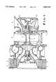
- FIG. 1is a cross section through an exhaust turbocharger of the type for which the mounting of the invention is suitable.
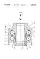
- FIG. 2shown, on a large scale, a cross section through the mounting and lubricating system of the exhaust turbocharger of FIG. 1.
- the turbocharger housing 1encloses a turbine wheel 2 and a compressor wheel 3 which are arranged on a shaft 4 which is supported by a bearing system 5 and 5a.
- the bearing system 5is shown in FIG. 2. It includes two outer races 7 for two rows of rolling bodies in the form of rows of balls 8 and 8a. The two outer races are arranged in a one piece bearing outer ring 6.
- the bearing inner ringis in three parts in FIG. 2, including a first inner ring 9 defining the race for the right hand row 8a and a two part second inner ring having parts 10 and 11 which both define the race for the left hand row 8.
- the right hand row of balls 8a, together with the first inner ring 9is developed as an angular ball bearing.
- the left hand row of balls with the axially split two inner ring parts 10 and 11is developed as a four-point bearing.
- the balls 8are contacted by both of the inner ring parts 10 and 11.
- the first inner ring part 10extends axially from the left or axially away from the first inner ring to about the middle of the row of balls 8.
- the axial length and placement of the second inner ring part 11are selected so that its opposite axial sides are each radially below a respective one of the two rows of balls, which enables lubricant from the second ring part 11 to flow to both rows 8 and 8a of balls.
- the first inner ring 9extends axially to the left to be radially inside the four point ball bearing so that the first inner ring 9 supports the inner ring parts 10 and 11 of the second inner ring. This completes channels for lubricant outside the first inner ring 9 and inside the ring parts 10 and 11 of the second inner ring.
- annular space 13located toward one axial side of the bearing.
- at least one circumferentially limited, axially extending passage in the form of a groove 14is provided in the periphery of the inner ring 9.
- One axial end of the groove 14is in communication with the annular space 13 and the other axial end communicates with an annular channel 12 formed in the inner periphery of the second inner ring part 11.
- lubricant transmission channels 15, 15aextend from the annular channel 12 to the two axially opposite side surfaces of the inner ring part 11 and these sides are respectively radially inward of the two rows of balls 8 and 8a.
- the number and spacing of the grooves 14, as well as the spacing of the grooves 14 and the channels 15, 15amay be different from each other and are adapted to each other so that lubricant flow to both rows of balls may be uniform, thereby preventing a preferred flow of lubricant to only one of the rows of balls 8 or 8a.
- the inner ring 9is furthermore provided with an oil slinger extension 16 which throws off excess oil which migrates onto it.
- the outer ring 6is provided with axially extending protrusions 17.
- the bore of the inner ring 9 of the angular ball bearingis recessed at 18 which extends over the axial width of the bearing. The axial ends of that recess define seating surfaces located toward the ends of the bore for centering the rotor shaft.
Landscapes
- Engineering & Computer Science (AREA)
- General Engineering & Computer Science (AREA)
- Mechanical Engineering (AREA)
- Rolling Contact Bearings (AREA)
- Supercharger (AREA)
- Lubrication Of Internal Combustion Engines (AREA)
Abstract
Description
Claims (15)
Applications Claiming Priority (2)
| Application Number | Priority Date | Filing Date | Title |
|---|---|---|---|
| DE19538553.3 | 1995-10-17 | ||
| DE19538553ADE19538553B4 (en) | 1995-10-17 | 1995-10-17 | Rotor bearing of an exhaust gas turbocharger |
Publications (1)
| Publication Number | Publication Date |
|---|---|
| US5683224Atrue US5683224A (en) | 1997-11-04 |
Family
ID=7775022
Family Applications (1)
| Application Number | Title | Priority Date | Filing Date |
|---|---|---|---|
| US08/724,439Expired - LifetimeUS5683224A (en) | 1995-10-17 | 1996-10-01 | Rotor mounting of an exhaust turbocharger |
Country Status (4)
| Country | Link |
|---|---|
| US (1) | US5683224A (en) |
| EP (1) | EP0769630B1 (en) |
| JP (1) | JP3931285B2 (en) |
| DE (1) | DE19538553B4 (en) |
Cited By (7)
| Publication number | Priority date | Publication date | Assignee | Title |
|---|---|---|---|---|
| EP1348879A1 (en)* | 2002-03-29 | 2003-10-01 | Isuzu Motors Limited | Two row tapered roller bearing with oil supply through a spacer of a split inner ring |
| US6682222B2 (en)* | 2001-08-22 | 2004-01-27 | General Electric Company | Bi-directional oil scoop for bearing lubrication |
| FR2923562A1 (en)* | 2007-11-12 | 2009-05-15 | Snr Roulements Sa | Ball bearing assembly for e.g. guiding shaft of turbocharger in boat, has ball bearings, where balls made of ceramic material e.g. silicon nitride, are rolled between rings of bearings and have points contacted with rings of one of bearings |
| US20110158803A1 (en)* | 2008-04-22 | 2011-06-30 | Schaeffler Technologies Gmbh & Co. Kg | Bearing arrangement having a double-row roller bearing, turbocharger and method for feeding a lubricant to the rows of rolling bodies of a double-row roller bearing |
| US8616777B1 (en) | 2012-11-16 | 2013-12-31 | Pratt & Whitney Canada Corp. | Bearing assembly with inner ring |
| US10156171B2 (en) | 2015-08-07 | 2018-12-18 | Cummins Emission Solutions Inc. | Mounting aftertreatment systems from service joints |
| FR3095481A1 (en)* | 2019-04-25 | 2020-10-30 | Safran Aircraft Engines | Double row angular contact ball bearing comprising emergency axial retention means integrated into the bearing |
Families Citing this family (9)
| Publication number | Priority date | Publication date | Assignee | Title |
|---|---|---|---|---|
| DE102006031956A1 (en)* | 2006-07-11 | 2008-01-17 | Schaeffler Kg | Double-row ball bearing for motor vehicle, has rows of bearing balls rolling between inner and outer rings, where row of balls are assigned to four-point-ball bearing and angular ball bearing, and inner ring is divided into path areas |
| JP4838770B2 (en)* | 2007-07-13 | 2011-12-14 | 三菱重工業株式会社 | Turbo compressor and turbo refrigerator |
| DE102007034813A1 (en) | 2007-07-25 | 2009-01-29 | Schaeffler Kg | Angular contact ball bearing in tandem arrangement and bearing arrangement with the angular contact ball bearing |
| DE102007061017B4 (en)* | 2007-12-18 | 2012-08-16 | Schaeffler Technologies Gmbh & Co. Kg | Bearing arrangement for mounting a pinion shaft |
| CN101793289A (en)* | 2010-03-17 | 2010-08-04 | 上海大学 | Oil-air lubrication high-speed mixing double-row ball bearing |
| DE102014222094A1 (en)* | 2014-10-29 | 2016-05-04 | Aktiebolaget Skf | roller bearing |
| CN105972071A (en)* | 2016-07-12 | 2016-09-28 | 江苏万达特种轴承有限公司 | Double-inner-ring eight-point contact type bearing |
| CN109058079A (en) | 2018-09-14 | 2018-12-21 | 珠海格力电器股份有限公司 | Liquid spray ring and refrigerant lubricated bearing assembly |
| CN112283242A (en)* | 2020-09-30 | 2021-01-29 | 人本股份有限公司 | hub unit bearing |
Citations (9)
| Publication number | Priority date | Publication date | Assignee | Title |
|---|---|---|---|---|
| US1642979A (en)* | 1924-06-23 | 1927-09-20 | Union Tool Kk | Unitary structure for crown sheaves |
| US3090544A (en)* | 1962-05-02 | 1963-05-21 | Schwitzer Corp | Air lubricated bearing |
| EP0143950A2 (en)* | 1983-11-30 | 1985-06-12 | BBC Brown Boveri AG | Bearing assembly of a turbo charger with tandem roller bearings |
| US4824264A (en)* | 1987-02-21 | 1989-04-25 | Dr. Ing. H.C.F. Porsche Aktiengesellschaft | Bearing of an axle drive bevel pinion |
| US4988218A (en)* | 1988-11-02 | 1991-01-29 | Quaglia Lawrence D | Thrust bearing for a pressurized lubricating system and an O-ring |
| US5106209A (en)* | 1991-08-07 | 1992-04-21 | General Electric Company | Multi-plane lubricated bearing assembly |
| EP0504138A1 (en)* | 1989-12-12 | 1992-09-23 | Allied Signal Inc | Turbocharger bearing retention and lubrication system. |
| US5248245A (en)* | 1992-11-02 | 1993-09-28 | Ingersoll-Dresser Pump Company | Magnetically coupled centrifugal pump with improved casting and lubrication |
| US5399027A (en)* | 1993-06-25 | 1995-03-21 | Nsk Ltd. | Rolling bearing for a high speed rotation |
Family Cites Families (5)
| Publication number | Priority date | Publication date | Assignee | Title |
|---|---|---|---|---|
| DE1127673B (en)* | 1958-05-17 | 1962-04-12 | Voith Gmbh J M | Device for the lubrication of two or more tapered roller bearings, especially on the pinion bearings of axle drives |
| FR2666389B1 (en)* | 1990-09-04 | 1992-10-23 | Roulements Soc Nouvelle | PROCESS FOR PRODUCING A BEARING COLLAR AND BEARING ASSEMBLY EQUIPPED WITH SUCH A COLLAR. |
| JP2953828B2 (en)* | 1991-08-19 | 1999-09-27 | 日本トムソン株式会社 | Stud type track roller bearing |
| US5183342A (en)* | 1991-12-16 | 1993-02-02 | General Electric Company | Lubricated bearing assembly |
| DE4334339A1 (en)* | 1993-10-08 | 1995-04-13 | Abb Management Ag | Exhaust turbocharger |
- 1995
- 1995-10-17DEDE19538553Apatent/DE19538553B4/ennot_activeExpired - Fee Related
- 1996
- 1996-10-01USUS08/724,439patent/US5683224A/ennot_activeExpired - Lifetime
- 1996-10-04JPJP29698996Apatent/JP3931285B2/ennot_activeExpired - Lifetime
- 1996-10-12EPEP96116391Apatent/EP0769630B1/ennot_activeExpired - Lifetime
Patent Citations (9)
| Publication number | Priority date | Publication date | Assignee | Title |
|---|---|---|---|---|
| US1642979A (en)* | 1924-06-23 | 1927-09-20 | Union Tool Kk | Unitary structure for crown sheaves |
| US3090544A (en)* | 1962-05-02 | 1963-05-21 | Schwitzer Corp | Air lubricated bearing |
| EP0143950A2 (en)* | 1983-11-30 | 1985-06-12 | BBC Brown Boveri AG | Bearing assembly of a turbo charger with tandem roller bearings |
| US4824264A (en)* | 1987-02-21 | 1989-04-25 | Dr. Ing. H.C.F. Porsche Aktiengesellschaft | Bearing of an axle drive bevel pinion |
| US4988218A (en)* | 1988-11-02 | 1991-01-29 | Quaglia Lawrence D | Thrust bearing for a pressurized lubricating system and an O-ring |
| EP0504138A1 (en)* | 1989-12-12 | 1992-09-23 | Allied Signal Inc | Turbocharger bearing retention and lubrication system. |
| US5106209A (en)* | 1991-08-07 | 1992-04-21 | General Electric Company | Multi-plane lubricated bearing assembly |
| US5248245A (en)* | 1992-11-02 | 1993-09-28 | Ingersoll-Dresser Pump Company | Magnetically coupled centrifugal pump with improved casting and lubrication |
| US5399027A (en)* | 1993-06-25 | 1995-03-21 | Nsk Ltd. | Rolling bearing for a high speed rotation |
Cited By (11)
| Publication number | Priority date | Publication date | Assignee | Title |
|---|---|---|---|---|
| US6682222B2 (en)* | 2001-08-22 | 2004-01-27 | General Electric Company | Bi-directional oil scoop for bearing lubrication |
| EP1348879A1 (en)* | 2002-03-29 | 2003-10-01 | Isuzu Motors Limited | Two row tapered roller bearing with oil supply through a spacer of a split inner ring |
| US20030185477A1 (en)* | 2002-03-29 | 2003-10-02 | Isuzu Motors Limited | Roller bearing oil feed device |
| US7036989B2 (en) | 2002-03-29 | 2006-05-02 | Isuzu Motors Limited | Roller bearing oil feed device |
| FR2923562A1 (en)* | 2007-11-12 | 2009-05-15 | Snr Roulements Sa | Ball bearing assembly for e.g. guiding shaft of turbocharger in boat, has ball bearings, where balls made of ceramic material e.g. silicon nitride, are rolled between rings of bearings and have points contacted with rings of one of bearings |
| US20110158803A1 (en)* | 2008-04-22 | 2011-06-30 | Schaeffler Technologies Gmbh & Co. Kg | Bearing arrangement having a double-row roller bearing, turbocharger and method for feeding a lubricant to the rows of rolling bodies of a double-row roller bearing |
| US8668432B2 (en)* | 2008-04-22 | 2014-03-11 | Schaeffler Technologies AG & Co. KG | Bearing arrangement having a double-row roller bearing, turbocharger and method for feeding a lubricant to the rows of rolling bodies of a double-row roller bearing |
| US8616777B1 (en) | 2012-11-16 | 2013-12-31 | Pratt & Whitney Canada Corp. | Bearing assembly with inner ring |
| US10156171B2 (en) | 2015-08-07 | 2018-12-18 | Cummins Emission Solutions Inc. | Mounting aftertreatment systems from service joints |
| US11248507B2 (en) | 2015-08-07 | 2022-02-15 | Cummins Emission Solutions Inc. | Mounting aftertreatment systems from service joints |
| FR3095481A1 (en)* | 2019-04-25 | 2020-10-30 | Safran Aircraft Engines | Double row angular contact ball bearing comprising emergency axial retention means integrated into the bearing |
Also Published As
| Publication number | Publication date |
|---|---|
| JP3931285B2 (en) | 2007-06-13 |
| EP0769630A3 (en) | 1997-10-22 |
| JPH09166026A (en) | 1997-06-24 |
| DE19538553B4 (en) | 2010-01-14 |
| EP0769630A2 (en) | 1997-04-23 |
| DE19538553A1 (en) | 1997-04-24 |
| EP0769630B1 (en) | 2002-05-02 |
Similar Documents
| Publication | Publication Date | Title |
|---|---|---|
| US5683224A (en) | Rotor mounting of an exhaust turbocharger | |
| US6758598B2 (en) | Integrated oil transfer sleeve and bearing | |
| US5183342A (en) | Lubricated bearing assembly | |
| US4329000A (en) | Self-contained, damped ball bearing assembly | |
| US5106209A (en) | Multi-plane lubricated bearing assembly | |
| US8668432B2 (en) | Bearing arrangement having a double-row roller bearing, turbocharger and method for feeding a lubricant to the rows of rolling bodies of a double-row roller bearing | |
| US4334720A (en) | Split-inner-ring ball bearing with lubrication structure | |
| US6176349B1 (en) | Bearing lubricating device | |
| GB961522A (en) | Bearing assembly | |
| US6357921B1 (en) | Radial-axial bearing assembly | |
| EP0942188A3 (en) | A sealing device for a rolling contact bearing | |
| FR2001380A1 (en) | ||
| CN101755135A (en) | Angular-contact ball bearing in a tandem arrangement, and bearing arrangement having the angular-contact ball bearing | |
| US5921349A (en) | Oil air lubricating apparatus | |
| WO1982000865A1 (en) | Self-contained,damped ball bearing assembly | |
| US5639166A (en) | Three-race bearing | |
| US8753018B2 (en) | Wheel end support bearing | |
| US20030072506A1 (en) | Bearing shell for use as a crankshaft thrust bearing | |
| US6513982B2 (en) | Package bearing with lubrication ports | |
| US10876578B2 (en) | Bearing assembly with inner rings and method of alignment | |
| US4385788A (en) | Roller bearing and construction thereof | |
| JP2008116034A (en) | Roller bearing | |
| JP2001165177A (en) | Bearing lubricating device | |
| JP3934706B2 (en) | Single or multi-row cylindrical roller bearings | |
| CN215890216U (en) | Aircraft engine |
Legal Events
| Date | Code | Title | Description |
|---|---|---|---|
| AS | Assignment | Owner name:FAG AIRCRAFT/SUPER PRECISION BEARINGS GMBH, GERMAN Free format text:ASSIGNMENT OF ASSIGNORS INTEREST;ASSIGNORS:SEBALD, WILHELM;KREISELMEIER, GERHARD;REEL/FRAME:008371/0313 Effective date:19960916 | |
| STCF | Information on status: patent grant | Free format text:PATENTED CASE | |
| FPAY | Fee payment | Year of fee payment:4 | |
| AS | Assignment | Owner name:FAG KUGELFISCHER GEORG SCHAFER AG, GERMANY Free format text:MERGER/CHANGE OF NAME DOCUMENT;ASSIGNORS:FAG AIRCRAFT/SUPER PRECISION BEARINGS GMBH;FAB AUTOMOBILTECHNIK AG;FAG INDUSTRIAL BEARINGS AG, (FORMER FAG OE MUND HANDEL AG);REEL/FRAME:014099/0575 Effective date:20021024 | |
| AS | Assignment | Owner name:FAG KUGELFISCHER AG, GERMANY Free format text:CHANGE OF NAME;ASSIGNOR:FAG AIRCRAFT/SUPER PRECISION BEARING GMBH;REEL/FRAME:015931/0414 Effective date:20040621 | |
| FPAY | Fee payment | Year of fee payment:8 | |
| AS | Assignment | Owner name:SCHAEFFLER KG, GERMANY Free format text:CERTIFICATION;ASSIGNOR:FAG KUGELFISCHER AG;REEL/FRAME:020279/0690 Effective date:20060101 | |
| FPAY | Fee payment | Year of fee payment:12 | |
| AS | Assignment | Owner name:INA-SCHAEFFLER AG, GERMANY Free format text:MERGER;ASSIGNOR:FAG KUGELFISCHER AG & CO. OHG;REEL/FRAME:037406/0817 Effective date:20060101 |