US5682379A - Wireless personal local area network - Google Patents
Wireless personal local area networkDownload PDFInfo
- Publication number
- US5682379A US5682379AUS08/500,977US50097796AUS5682379AUS 5682379 AUS5682379 AUS 5682379AUS 50097796 AUS50097796 AUS 50097796AUS 5682379 AUS5682379 AUS 5682379A
- Authority
- US
- United States
- Prior art keywords
- network
- network device
- radio
- devices
- microlan
- Prior art date
- Legal status (The legal status is an assumption and is not a legal conclusion. Google has not performed a legal analysis and makes no representation as to the accuracy of the status listed.)
- Expired - Lifetime
Links
- 238000004891communicationMethods0.000claimsabstractdescription105
- 230000005540biological transmissionEffects0.000claimsabstractdescription43
- 230000002093peripheral effectEffects0.000abstractdescription33
- 238000012546transferMethods0.000abstractdescription6
- 238000010586diagramMethods0.000description15
- 230000009977dual effectEffects0.000description7
- 230000000875corresponding effectEffects0.000description6
- 239000002674ointmentSubstances0.000description5
- 238000007639printingMethods0.000description5
- 238000000034methodMethods0.000description3
- 230000037361pathwayEffects0.000description3
- 230000003213activating effectEffects0.000description2
- 230000008901benefitEffects0.000description2
- 238000013480data collectionMethods0.000description2
- 230000000694effectsEffects0.000description2
- 208000014674injuryDiseases0.000description2
- 230000004048modificationEffects0.000description2
- 238000012986modificationMethods0.000description2
- 238000003032molecular dockingMethods0.000description2
- 238000012544monitoring processMethods0.000description2
- 230000008569processEffects0.000description2
- 239000013589supplementSubstances0.000description2
- 238000012795verificationMethods0.000description2
- 208000027418Wounds and injuryDiseases0.000description1
- 230000004888barrier functionEffects0.000description1
- 230000001413cellular effectEffects0.000description1
- 230000008859changeEffects0.000description1
- 230000008867communication pathwayEffects0.000description1
- 230000006378damageEffects0.000description1
- 230000000593degrading effectEffects0.000description1
- 230000001627detrimental effectEffects0.000description1
- 238000005516engineering processMethods0.000description1
- 238000004880explosionMethods0.000description1
- 239000000835fiberSubstances0.000description1
- 210000000245forearmAnatomy0.000description1
- 125000000524functional groupChemical group0.000description1
- 238000010348incorporationMethods0.000description1
- 230000003993interactionEffects0.000description1
- 230000002452interceptive effectEffects0.000description1
- 230000002085persistent effectEffects0.000description1
- 230000000135prohibitive effectEffects0.000description1
- 230000009467reductionEffects0.000description1
- 230000035939shockEffects0.000description1
- 238000001228spectrumMethods0.000description1
- 210000003813thumbAnatomy0.000description1
- 230000008733traumaEffects0.000description1
- 230000001960triggered effectEffects0.000description1
Images


Classifications
- H—ELECTRICITY
- H04—ELECTRIC COMMUNICATION TECHNIQUE
- H04L—TRANSMISSION OF DIGITAL INFORMATION, e.g. TELEGRAPHIC COMMUNICATION
- H04L1/00—Arrangements for detecting or preventing errors in the information received
- H04L1/0001—Systems modifying transmission characteristics according to link quality, e.g. power backoff
- H04L1/0023—Systems modifying transmission characteristics according to link quality, e.g. power backoff characterised by the signalling
- H04L1/0032—Without explicit signalling
- H—ELECTRICITY
- H04—ELECTRIC COMMUNICATION TECHNIQUE
- H04L—TRANSMISSION OF DIGITAL INFORMATION, e.g. TELEGRAPHIC COMMUNICATION
- H04L1/00—Arrangements for detecting or preventing errors in the information received
- H04L1/0001—Systems modifying transmission characteristics according to link quality, e.g. power backoff
- H04L1/0023—Systems modifying transmission characteristics according to link quality, e.g. power backoff characterised by the signalling
- H04L1/0025—Transmission of mode-switching indication
- H—ELECTRICITY
- H04—ELECTRIC COMMUNICATION TECHNIQUE
- H04W—WIRELESS COMMUNICATION NETWORKS
- H04W52/00—Power management, e.g. Transmission Power Control [TPC] or power classes
- H04W52/04—Transmission power control [TPC]
- H04W52/18—TPC being performed according to specific parameters
- H04W52/28—TPC being performed according to specific parameters using user profile, e.g. mobile speed, priority or network state, e.g. standby, idle or non-transmission
- H04W52/287—TPC being performed according to specific parameters using user profile, e.g. mobile speed, priority or network state, e.g. standby, idle or non-transmission when the channel is in stand-by
- H—ELECTRICITY
- H04—ELECTRIC COMMUNICATION TECHNIQUE
- H04W—WIRELESS COMMUNICATION NETWORKS
- H04W84/00—Network topologies
- H04W84/02—Hierarchically pre-organised networks, e.g. paging networks, cellular networks, WLAN [Wireless Local Area Network] or WLL [Wireless Local Loop]
- H04W84/10—Small scale networks; Flat hierarchical networks
- H04W84/12—WLAN [Wireless Local Area Networks]
- H—ELECTRICITY
- H04—ELECTRIC COMMUNICATION TECHNIQUE
- H04W—WIRELESS COMMUNICATION NETWORKS
- H04W88/00—Devices specially adapted for wireless communication networks, e.g. terminals, base stations or access point devices
- H04W88/02—Terminal devices
- H04W88/06—Terminal devices adapted for operation in multiple networks or having at least two operational modes, e.g. multi-mode terminals
- H—ELECTRICITY
- H04—ELECTRIC COMMUNICATION TECHNIQUE
- H04W—WIRELESS COMMUNICATION NETWORKS
- H04W92/00—Interfaces specially adapted for wireless communication networks
- H04W92/02—Inter-networking arrangements
Definitions
- Computer terminals and peripheral devicesare now used in practically every aspect of life.
- Computer terminalscome in all shapes and sizes and vary greatly in terms of function, power and speed. Additionally, the number of peripheral devices which can be attached to the computer terminals is increasing. Many peripheral devices exist such as printers, modems, graphics, scanners, text scanners, codes readers, magnetic card readers, external monitors, voice command interfaces, external storage devices, and so on.
- Computer terminals and peripheralshave become dramatically smaller and more portable. Personal computers and peripherals are small enough to sit on the desk at work. Smaller still are leap top computers and notebook computers. There are computer terminals which are small enough to be mounted in a vehicle such as a delivery truck or on a fork lift. Still smaller are the hand held terminals typically used for their portability features where the user can carry the computer terminal in one hand and operate it with the other.
- the computer terminalstill must physically interface with the peripheral devices. Thus, there must either be a cable running from one of the computer terminal to each device or the computer terminal must be docked with the device while the information transfer is to take place.
- Peripheral devicessuch as printers and scanners of all types have been reduced dramatically in size to match the smallness of the computer terminals.
- a notebook computer operatormay wish to carry the computer and a cellular phone modem in a briefcase.
- an operatormay wish to have a hand-held computer terminal in one hand, a small portable printer attached to his belt, and a code reader in the other hand.
- the smallness of the computers and peripheralsmakes these demands possible but the required cabling makes these demands costly, inconvenient and even dangerous.
- LAN'sLocal Area Networks
- RFRadio Frequency
- the present inventionsolves many of the problems inherent.
- the mobile network deviceparticipates as a slave to the first network pursuant to the first protocol and as a master to the second network pursuant to the second protocol, and resolves conflicts between the first and second protocols in communication systems having devices which use battery power.
- the present inventionrelates generally to local area networks and, more specifically, to a communication system for maintaining connectivity between devices on networks which have different operating parameters while limiting the power drain of battery powered devices.
- a mobile network devicehas a single radio unit which is capable of participating in a first and second radio network which operate using a first and second communication protocol.
- the mobile network deviceparticipates as a slave to the first network pursuant to the first protocol and as a master to the second network pursuant to the second protocol, and resolves conflicts between the first and second protocols.
- a mobile network devicehas a first radio transceiver for communicating with a main radio network and a second radio transceiver for communicating with a radio subnetwork.
- the mobile network deviceparticipates as a slave to the main radio network and participates as a master to the radio subnetwork.
- a mobile network devicehas a single radio unit capable of participating in a first and a second radio network.
- the first and second radio networksoperate using a first and second communication protocol, respectively.
- the mobile network deviceparticipates as a slave to the first network pursuant to the first protocol and as a master to the second network pursuant to the second protocol, enters a state of low power consumption when not communicating with either the first or second network.
- an RF local area networkcontains a first network device which uses battery power to transmit data to a second network device.
- the second network devicedetermines a range value between the first and second network devices and transmits that value to the first network device so that the first network device can identify an appropriate, and potentially lower, data rate for subsequent transmission of data.
- the first network devicemay also consider its own battery parameters along with the received range value and identify an appropriate power level as well as data rate for subsequent transmissions.
- the second network devicedetermines the range value between the first and second network devices and, based on the range value, indicates to the first network device an appropriate, and potentially lower, data rate for subsequent data transmission to the second network device.
- the second network devicemay also consider battery parameter information received from the first network device and use that information along with the range value to indicate to the first network device an appropriate power level, as well as data rate, for subsequent transmissions by the first network device.
- FIG. 1aillustrates a warehouse environment incorporating a communication network which maintains communication connectivity between the various network devices according to the present invention.
- FIG. 1billustrates other features of the present invention in the use of a mobile vehicle and an associated microLAN network which is capable of detaching from the main communication network when moving out of range of the main network to perform a service, and reattaching to the main network when moving within range to automatically report on the services rendered.
- FIG. 2is a diagrammatic illustration of the use of a microLAN supporting roaming data collection by an operator according to the present invention.
- FIG. 3is a block diagram illustrating the functionality of RF transceivers built in accordance with the present invention.
- FIG. 4is a diagrammatic illustration of an alternate embodiment of the personal microLAN shown in FIG. 2.
- FIG. 5is a block diagram illustrating a channel access algorithm used by microLAN slave devices in according to the present invention.
- FIG. 6ais a timing diagram of the protocol using according to the present invention illustrating a typical communication exchange between a microLAN master device having virtually unlimited power resources and a microLAN slave device.
- FIG. 6bis a timing diagram of the protocol using according to the present invention illustrating a typical communication exchange between a microLAN master device having limited power resources and a microLAN slave device.
- FIG. 6cis also a timing diagram of the protocol used which illustrates a scenario wherein the microLAN master device fails to service microLAN slave devices.
- FIG. 7is a timing diagram illustrating the microLAN master device's servicing of both the high powered main communication network and the low powered microLAN subnetwork, with a single or plural radio transceivers, in accordance with the present invention.
- FIGS. 8 and 9are block diagrams illustrating additional power saving features according to the present invention wherein ranging and battery parameters are used to optimally select the appropriate data rate and power level of subsequent transmissions.
- FIG. 1aillustrates a warehouse environment incorporating a communication network which maintains communication connectivity between the various network devices according to the present invention.
- a workerutilizes a computer terminal 7 and a code reader 9 to collect data such as identifying numbers or codes on warehoused goods, such as the box 10.
- the numbers and codesare collected, they are forwarded through the network to a host computer 11 for storage and cross-referencing.
- the host computer 11may, for example, forward cross-referenced information relating to the collected numbers or codes back through the network for display on the terminal 7 or for printing on a printer 13.
- the collectedmay be printed from the computer terminal 7 directly to the printer 13.
- Other exemplary communication pathways supported by the present inventioninclude messages exchanged between the computer terminal 7 and other computer terminals (not shown) or the host computer 11.
- the hand-held computer terminal 7receives its power from either an enclosed battery or a forklift battery (not shown) via a docking station within the forklift 14.
- the code reader 9operates on portable battery power as may the printer 13. The arrangement of the communication network, communication protocols used, and data rate and power level adjustments help to optimize battery conservation without substantially degrading network performance.
- the overall communication network of the present inventionis arranged into two functional groups: 1) a main communication network; and 2) a microLAN network.
- the main communication network in the illustrated warehouse embodimentincludes a hard-wired backbone LAN 19 and base stations 15 and 17.
- a host computer 11 and any other non-mobile network device located in the vicinity of the backbone LAN 19can be directly attached to the backbone LAN 19.
- mobile devices and remotely located devicesmust maintain connectivity to the backbone LAN 19 through either a single base station such as the base station 15, or through a multi-hop network of base stations such as is illustrated by the base stations 15 and 17.
- the base stations 15 and 17contain a higher power transmitter, and provide coverage over the entire warehouse floor.
- the multi-hop plurality of base stations 17may be necessary. Otherwise, the backbone LAN 19 must be extended to connect all of the base stations 17 directly to provide sufficient radio coverage. Through the main communication network, relatively stable, long range wireless and hard-wired communication is maintained.
- Network devices that are mobile or remoteare fitted with RF transceivers.
- the fitted transceiveris selected to yield approximately the same transmission power as do the base stations 15 and 17.
- communicationis generally localized to a small area and, as such, only requires relatively lower power, short range transceivers.
- the devices which participate in the localized, short range communicationform what is termed herein a "microLAN".
- the interaction between peripheral devicessuch as the printer 13, modem 23, and code reader 9 with the terminal 7 provide a justification for a microLAN configuration.
- the printer 13may be located in a dock with the sole assignment of printing out forms based on the code information gathered from boxes delivered to the dock. In such an example, only when the forklift 14 enters the dock area should the printer 13 begin printing the collected code information.
- communicating via the base stations 15 and 17 with the required high powered transceiversis avoided by establishing a microLAN on the dock.
- the printer 13is fitted with a low power microLAN transceiver for short range communication directly to the computer terminal 7 in the forklift 14.
- the computer terminal 7is also fitted with a transceiver capable of direct, low power communication with the printer 13.
- the computer terminal 7transmits the code information at a relatively low power level to the printer 13. While in range (whether printing or not), the computer terminal 7 and printer 13 together participate in a low power, microLAN network.
- the code reader 9is also fitted with a microLAN transceiver. Whenever the code reader 9 is used, collected code signals and counterpart information are not directly exchanged with the host computer 11 via the main network. Instead, in the illustrated example, the computer terminal 7 is configured to be able to communicate not only within the microLAN but also through the main communication network. This is accomplished by fitting the computer terminal 7 with a transceiver(s) capable of communicating on both networks (see discussion related to FIG. 3 below).
- the code reader 9first transmits to the computer terminal 7 via the microLAN, i.e., through the microLAN transceivers in each device. Upon receipt of the data, the computer terminal 7 relays the information to one of the base stations 15 and 17 for forwarding to the host 11. Communication from the host 11 to the code reader 9 is accomplished via the same pathway.
- any two devices in the microLAN networkcould communicate to each other.
- the modem 23could receive data and directly transmit it to the printer 13 for printing.
- the code reader 9might choose to directly communicate code signals to other network devices via the modem 23.
- a microLAN base station 21is provided which may be directly connected to the backbone LAN 19 (as shown) or indirectly connected via the base stations 15 and 17.
- the microLAN base station 21is positioned in the vicinity of a other microLAN network devices and thereafter becomes a participant.
- microLAN communication flowing to or from the main communication networkavoids high power radio transmissions altogether.
- a stationary microLAN base stationmay not always be an option when all of the microLAN participants are mobile. In such cases, a high power transmission to reach the main communication network may be required.
- microLAN devicesthe participating devices
- the transceiver capabilityto reach the main communication network.
- at least one microLAN deviceneeds to have that capability to maintain overall network connectivity.
- FIG. 1billustrates other features of the present invention in the use of a mobile vehicle and an associated microLAN network which is capable of detaching from the main communication network when moving out of range of the main network to perform a service, and reattaching to the main network when moving within range to automatically report on the services rendered.
- a delivery truck 33provides a focal point for microLAN access.
- a storage terminal 31is docked so as to draw power from the truck 33's battery supply.
- the storage terminal 31is configured with a microLAN transceiver.
- a computer terminal 7also configured as a microLAN device may either be docked or ported. Because of greater battery access and because of the amount of data to transfer, the storage terminal 31 is also configured to communicate with the main communication network.
- the truckPrior to making a delivery, the truck enters a docking area for loading. As goods are loaded into the truck, the driver enters information regarding each loaded good into the storage terminal 31 via either the terminal 7 or the code reader 9 (FIG. 1a) using the microLAN network communications. This loading might also be accomplished automatically as the forklift 14 comes into range of the delivery truck 31, joins the microLAN network, and transmits the previously collected data as described above in relation to FIG. 1a. In addition, as information regarding a good is received and stored, the storage device might also request further information regarding any or all of the goods via the microLAN's link to the host computer 11 through the main communication network.
- the microLAN base station 21if located on the dock could provide a direct low power microLAN connection to the backbone LAN 19 and to the host computer 11. Otherwise, because of the normal data flow pathway and because of its greatest access to available power, the storage terminal 31 is configured with a transceiver capable of communicating with the main communication network via the base stations 15 and 17. When fully loaded and prior to leaving the dock, the storage device 31 communicates via the microLAN to the printer 13 to generate a printout of information relating to the loaded goods. In addition, the information is transmitted via the microLAN to the modem 23 for relay to a given destination site. Upon reaching the destination, the storage terminal 31 detects and participates in the microLAN of the delivery site dock.
- the truck 33leaves the dock in the morning with the addresses and directions of the service destinations, technical manuals, and service notes which have been selectively downloaded from the host computer via the main network and microLAN to the storage terminal 31.
- the storage terminal 31 and the computer terminal 7automatically form an independent, detached microLAN.
- the drivercollects information using the terminal 7 either as the data is collected if within microLAN transmission range of the storage terminal 31, or as soon as the terminal 7 comes within range. Through the detached microLAN network such information is available on the computer terminal.
- the detached microLANUpon returning to the dock, as soon as the independent microLAN formed between the storage terminal 31 and the computer terminal 7 come within microLAN range of the microLAN devices on the dock, the detached microLAN automatically merges with the dock's microLAN (becomes "attached"), and the storage terminal 31 automatically transfers the service information to the host computer 11 which uses the information for billing and in formulating the service destinations which will be automatically downloaded the next day.
- FIG. 2is a diagrammatic illustration of another embodiment using a microLAN to supporting roaming data collection by an operator according to the present invention.
- an operator 61roams the warehouse flood he carries with him a microLAN comprising the terminal 7, code reader 9 and a portable printer 58.
- the operatorcollect information regarding goods, such as the box 10, with the code reader 9 and the terminal 7. If the power resources are equal, the terminal 7 may be designated to also communicate with the main communication network. Specifically, corresponding information to the code data must be retrieved from the host computer 11, collected code information and retrieved corresponding information needs to be displayed on the terminal 7, and, after viewing for verification the information needs to be printed on the printer 58. Because of this data flow requirement, the computer terminal 7 is selected as the microLAN device which must also carry the responsibility of communicating with the main communication network.
- the microLAN networkbecomes detached from the main communication network.
- the detached microLANit might be possible for the detached microLAN to function, all communication with the host computer 11 through the main communication network is placed in a queue awaiting reattachment. As soon as the detached microLAN comes within range of an attached microLAN device, i.e., a device attached to the main network, the queued communications are related to the host.
- the code reader 9may be designated as a backup to the terminal 7 for performing the higher power communication to the main communication network.
- the code reader 9will take over the role if it is next in line to perform the backup service. Thereafter, when the computer terminal 7 is powered up, it monitors the microLAN channel, requests and regains from the code reader 9 the role of providing an interface with the main computer network. This, however, does not restrict the code reader 9 from accessing the main computer network although the reader 9 may choose to use the computer terminal 7 for power conservation reasons.
- the terminal 7will attempt to pass the burden of providing main network access to other microLAN backup devices. If no backup device exists in the current microLAN, the computer terminal 7 may refuse all high power transmissions to the main communication network. Alternatively, the computer terminal 7 may either refuse predetermined select types of requests, or prompt the operator before performing any transmission to the main network. However, the computer terminal 7 may still listen to the communications from the main communication network and inform microLAN members of waiting messages.
- FIG. 3is a block diagram illustrating the functionality of RF transceivers built in accordance with the present invention.
- the transceiver 110may also be built-in or externally attached via available serial, parallel or ethernet connectors for example.
- the transceivers used by potential microLAN master devicesmay vary from those used by microLAN slave devices (as detailed below), they all contain the illustrated functional blocks.
- the transceiver 110contains a radio unit 112 which attaches to an attached antenna 113.
- the radio unit 112 used in microLAN slave devicesneed only provide reliable low power transmissions, and are designed to conserve cost, weight and size.
- Potential microLAN master devicesnot only require the ability to communicate with microLAN slave devices, but also require higher power radios to also communicate with the main network.
- potential microLAN master devices and other non-microLAN slave devicesmight contain two radio units 112 (or two transceivers 110)--one serving the main network and the other serving the microLAN network--else only contain a single radio unit to service both networks.
- a dual radio unit configuration for potential microLAN master devicesprovides several advantages. For example, simultaneous transceiver operation is possible by choosing a different operating band for each radio.
- a 2.4 GHz radiois included for main network communication while a 27 MHz radio supports the microLAN network.
- MicroLAN slave devicesreceive only the 27 MHz radio, while the non-potential microLAN participants from the main network are fitted with only the 2.4 GHz radios.
- Potential microLAN master devicesreceive both radios.
- the low power 27 MHz microLAN radiois capable of reliably transferring information at a range of approximately 40 to 100 feet asynchronously at 19.2K BPS.
- An additional benefit of using the 27 MHz frequencyis that it is an unlicensed frequency band.
- the 2.4 GHz radioprovides sufficient power (up to 1 Watt) to communicate with other main network devices. Many different frequency choices could also be made such as the 900 MHz band, etc.
- a single radio unit configurationis used for potential microLAN master devices.
- a dual mode 2.4 GHz radiosupports both the microLAN and main networks.
- the 2.4 GHz radiooperates at a low power level (sub-milliwatt) to support microLAN communication at relatively close distances (20-30 feet).
- the 2.4 GHz radioprovides relatively long distance communication connectivity with the main network.
- all network devicesmight be fitted with such a dual mode radio, only microLAN master devices use both modes.
- MicroLAN slave deviceswould only use the low power mode while all other main network devices would use only the high power mode. Because of this, to save cost, microLAN slave devices are fitted with a single mode radio operating in the microLAN mode.
- Non-microLAN participantsare also fitted with a single mode (main mode) radio unit for cost savings.
- a microprocessor 120controls the information flow between through the transceiver 110.
- the interface 115connects the transceiver 110 to a selected computer terminal, a peripheral device or other network device.
- Many different interfaces 115are used and the choice will depend upon the connection port of the device to which the transceiver 110 will be attached. Virtually any type of interface 110 could be adapted for use with the transceiver 110 of the present invention. Common industry interface standards include RS-232, RS-422, RS-485, 10BASE2 Ethernet, 10BASE5 Ethernet, 10BASE-T Ethernet, fiber optics, IBM 4/16 Token Ring, V.11, V.24, V.35, Apple Localtalk and telephone interfaces.
- the microprocessor 120maintains a radio independent, interface protocol with the attached network device, isolating the attached device from the variations in radios being used.
- the microprocessor 120also controls the radio unit 112 to accommodate communication with the either the main network (for main mode radios), the microLAN (for microLAN radios), or both (for dual mode radios). More specifically, in a main mode transceiver, the microprocessor 120 utilizes a main protocol to communicate with the main network. Similarly, in a microLAN mode transceiver, the microprocessor 120 operates pursuant to a microLAN protocol to communicate in the microLAN network. In the dual mode transceiver, the microprocessor 120 manages the use of and potential conflicts between both the main and microLAN protocols. Detail regarding the main and microLAN protocols can be found in reference to FIGS. 6-9 below.
- the microprocessor 120controls the power consumption of the radio 112, itself and the interface 115 for power conservation. This is accomplished in two ways. First, the microLAN and main protocols are designed to provide for a low power mode or sleep mode during periods when no communication involving the subject transmitter is desired as described below in relation to FIGS. 6-7. Second, both protocols are designed to adapt in both data rate and transmission power based on power supply (i.e., battery) parameters and range information as described in reference to FIGS. 8-9.
- power supplyi.e., battery
- each deviceis assigned a unique address.
- the transceiver 10can either have a unique address of its own or can use the unique address of the device to which it is attached.
- the unique address of the transceivercan either be one selected by the operator or system designer or one which is permanently assigned at the factory such as an IEEE address.
- the address 121 of the particular transceiver 110is stored with the microprocessor 120.
- the microLAN master deviceis shown as being either a microLAN base station or a mobile or potable computer terminal. From a data flow viewpoint in considering the fastest access through the network such choices for the microLAN master devices appear optimal. However, any microLAN device might be assigned the role of the master, even those that do not seem to provide an optimal data flow pathway but may provide for optimal battery usage. For example, in the personal microLAN network of FIG. 2, because of the support from the belt 59, the printer might contain the greatest battery capacity of the personal microLAN devices. As such, the printer might be designated the microLAN master device and be fitted with either a dual mode radio or two radios as master devices require.
- the printer, or other microLAN slave devicesmight also be fitted with such required radios to serve only as a microLAN master backup. If the battery power on the actual microLAN master, i.e., the hand-held terminal 7 (FIG. 20, drops below a preset threshold, the backup master takes over.
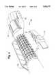
- FIG. 4is a drawing which illustrates an embodiment of the personal microLAN shown in FIG. 2 which designates a printer as the microLAN master device.
- a computer terminal 170is strapped to the forearm of the operator.
- a code reader 171straps to the back of the hand of the user and is triggered by pressing a button 173 with the thumb. Because of their relatively low battery energy, the computer terminal 170 and code reader 171 are designated microLAN slave devices and each contain a microLAN transceiver having a broadcast range of two meters or less. Because of its greater battery energy, the printer 172 contains a dual mode radio and is designated the microLAN master device.
- FIG. 5is a block diagram illustrating a channel access algorithm used by microLAN slave devices in according to the present invention.
- a slave devicewhen a slave device has a message to send, it waits for an idle sense message to be received from the microLAN master device at a block 183.
- the slave deviceexecutes a back-off protocol at a block 187 by in an attempt to avoid collisions with other slave devices waiting to transmit.
- each waiting slaveinstead of permitting every slave device from repeatedly transmitting immediately after an idle sense message is received, each waiting slave is required to first wait for a pseudo-random time period before attempting a transmission. The pseudo-random back-off time period is generated and the waiting takes place at a block 187.
- the channelis sensed to determine whether it is clear for transmission. If not, a branch is made back to the block 183 to attempt a transmission upon receipt of the next idle sense message. If the channel is still clear, at a block 191, a relatively small "request to send" type packet is transmitted indicating the desire to send a message. If no responsive "clear to send" type message is received from the master device, the slave device assumes that a collision occurred at a block 193 and branches back to the block 183 to try again. If the "clear to send" message is received, the slave device transmits the message at a block 195.
- FIG. 6ais a timing diagram of the protocol used according to the present invention illustrating a typical communication exchange between a microLAN master device having virtually unlimited power resources and a microLAN slave device.
- Time line 201represents communication activity by the microLAN master device while time line 203 represents the corresponding activity by the microLAN slave device.
- the masterperiodically transmits an idle sense message 205 indicating that it is available for communication or that it has data for transmission to a slave device. Because the master has virtually unlimited power resources, it "stays awake” for the entire time period 207 between the idle sense messages 205. In other words, the master does not enter a power conserving mode during the time periods 207.
- the slave deviceuses a binding protocol (discussed below with regard to FIG. 6c) to synchronize to the master device so that the slave may enter a power conserving mode and still monitor the idle sense messages of the master to determine if the master requires servicing. For example, referring to FIG. 6a, the salve device monitors an idle sense message of the master during a time period 209, determines that no servicing is required and enters a power conserving mode during the time period 211. The slave then activates during a time period 213 to monitor the next idle sense message of the master. Again, the slave determines that no servicing is required and enters a power conserving mode during a time period 215.
- a binding protocoldiscussed below with regard to FIG. 6c
- the slaveWhen the slave activates again during a time period 217 to monitor the next idle sense message, it determines from a "request to send" type message from the master that the master has data for transmission to the slave.
- the salveresponds by sending a "clear to send” type message during the time period 217 and stays activated in order to receive transmission of the data.
- the masteris thus able to transmit the data to the slave during a time period 219.
- the slaveagain enters a power conserving mode during a time period 223 and activates again during the time period 225 to monitor the next idle sense message.
- the slavemay have data for transfer to the master. If so, the slave indicates as such to the master by transmitting a message during the time period 217 and then executes a backoff algorithm to determine how long it must wait before transmitting the data. The slave determines from the backoff algorithm that it must wait the time period 227 before transmitting the data during the time period 221. The slave devices use the backoff algorithm in an attempt to avoid the collision of data with that from other slave devices which are also trying to communicate with the master. The backoff algorithm is discussed more fully above in reference to FIG. 5.
- the idle sense messages of the mastermay also aid in scheduling communication between two slave devices. For example, if a first slave device has data for transfer to a second slave device, the first slave sends a message to the master during the time period 209 requesting communication with the second slave. The master then broadcasts the request during the next idle sense message. Because the second slave is monitoring the idle sense message, the second slave receives the request and stays activated at the end of the idle sense message in order to receive the communication. Likewise, because the first slave is also monitoring the idle sense message, it too receives the request and stays activated during the time period 215 to send the communication.
- FIG. 6bis a timing diagram of the protocol used according to the present invention illustrating a typical communication exchange between a microLAN master having limited power resources and a microLAN slave device. This exchange is similar to that illustrated in FIG. 6a except that, because it has limited power resources, the master enters a power conserving mode.
- the masterlistens to determine if the channel is idle. If the channel is idle, the master transmits an idle sense message 205 and then waits a time period 231 to determine if any devices desire communication. If no communication is desired, the master enters a power conserving mode during a time period 233 before activating again to listen to the channel. If the channel is not idle, the master does not send the idle sense message and enters a power saving mode for a time period 235 before activating again to listen to the channel.
- Communication between the master and slave devicesis the same as that discussed above in reference to FIG. 6a except that, after sending or receiving data during the time period 219, the master device enters a power conserving mode during the time period 237.
- FIG. 6cis also a timing diagram of the protocol used which illustrates a scenario wherein the microLAN master device fails to service microLAN slave devices.
- the master deviceperiodically sends an idle sense message 205, waits a time period 231, and enters a power conserving mode during a time period 233 as discussed above in reference to FIG. 6b.
- the salve devicemonitors the idle sense messages during time periods 209 and 213 and enters a power conserving mode during time periods 211 and 215. For some reason, however, the master stops transmitting idle sense messages. Such a situation may occur, for example, if the master device is portable and is carried outside the range of the slave's radio.
- the slaveunsuccessfully attempts to monitor an idle sense message.
- the slavethen goes to sleep for a time period 243 and activates to attempt to monitor a next idle sense message during a time period 245, but is again unsuccessful.
- the slave devicethereafter initiates a binding protocol to attempt to regain synchronization with the master. While two time periods (241 and 245) are shown, the slave may initiate such a protocol after any number of unsuccessful attempts to locate an idle sense message. With this protocol, the slave stays active for a time period 247, which is equal to the time period from one idle sense message to the next, in an attempt to locate a next idle sense message. If the slave is again unsuccessful, it may stay active until it locates an idle sense message from the master, or, if power consumption is a concern, the slave may enter a power conserving mode at the end of the time period 247 and activate at a later time to monitor for an idle sense message.
- one of the slave devicesmay take over the functionality of the master device.
- a backup devicehas the ability to communicate with devices on the main communication network. If the original master returns, it listens to the channel to determine idle sense messages from the backup, indicates to the backup that it has returned and then begins idle sense transmissions when it reestablishes dominance over the microLAN network.
- FIG. 7is a timing diagram illustrating the microLAN master device's servicing of both the high powered main communication network and the low powered microLAN subnetwork, with a single or plural radio transceivers, in accordance with present invention.
- Block 251represents typical communication activity of the master device.
- Line 253illustrates the master's communication with a base station on the main communication network while line 255 illustrates the master's communication with a slave device on the microLAN network.
- Lines 257 and 259illustrate corresponding communication by the base station and slave device, respectively.
- the base stationperiodically broadcasts HELLO messages 261 indicating that it is available for communication.
- the master devicemonitors the HELLO messages during a time period 263, and, upon determining that the base does not need servicing, enters a power conserving mode during a time period 265.
- the masterthen activates for a time period to monitor the next HELLO message from the base. If the master has data to send to the base, it transmits the data during a time period 271. Likewise, if the base has data to send to the master, the base transmits the data during a time period 269. Once the data is received or sent by the master, it may again enter a power conserving mode. While HELLO message protocol is discussed, a number of communication protocols may be used for communication between the base and the master device. As may be appreciated, the microLAN master device acts as a slave to base stations in the main communication network.
- Block 273illustrates a situation where the master encounters a communication conflict, i.e., it has data to send to or receive from the slave on the subnetwork at the same time it will monitor the main network for HELLO messages from the base.
- the masterhas two radio transceivers, the master can service both networks. If, however, the master only has one radio transceiver, the master chooses to service one network based on network priority considerations. For example, in block 273, it may be desirable to service the slave because of the presence of data rather than monitor the main network for HELLO messages from the base. On the other hand, in block 275, it may be more desirable to monitor the main network for HELLO messages rather than transmit an idle sense message on the subnetwork.
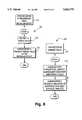
- FIGS. 8 and 9are block diagrams illustrating additional power saving features according to the present invention, wherein ranging and battery parameters are used to optimally select the appropriate data rate and power level for subsequent transmissions.
- network devicessuch as the computer terminal 7 in FIGS. 1-2 have the capability of performing high power transmissions, because of battery power concerns, the such devices are configured to utilize minimum transmission energy. For example if By adjusting either the power level and the data rate based. Adjustments are made based on ranging information and on battery parameters.
- battery conservation issuesalso justify the use such data rate and power adjustments. This process is described in more detail below in reference to FIGS. 8 and 9.
- FIG. 8is a block diagram which illustrates a protocol 301 used by a destination microLAN device and a corresponding protocol 303 used by a source microLAN device to adjust the data rate and possibly the power level for future transmission between the two devices.
- the destination deviceidentifies a range value at a block 313.
- the range valueis identified by considering the received signal strength indications (RSSI) of the incoming transmission.
- RSSIreceived signal strength indications
- RSSI circuitrymight be placed in all microLAN radios, the added expense may require that only microLAN master devices receive the circuitry. This would mean that only microLAN master devices would perform the function of the destination device.
- ranging valuesmight also be calculated using more expensive techniques such as adding GPS (Global Position Service) circuitry to both radios.
- GPSGlobal Position Service
- the range value transmitted at the block 313would consist of the GPS position of the destination microLAN device.
- the destination devicesubsequently transmits the range value to the slave device from which the transmission was received.
- the source microLAN deviceUpon receipt of the range value from the destination device at a block 321, the source microLAN device evaluates its battery parameters to identify a subsequent data rate for transmission at a block 323. If range value indicates that the destination microLAN device is very near, the source microLAN device selects a faster data rate. When the range value indicates a distant master, the source device selects a slower rate. In this way, even without adjusting the power level, the total energy dissipated can be controlled to utilize only that necessary to carry out the transmission. However, if constraints are placed on the maximum or minimum data rates, the transmission power may also need to be modified. For example, to further minimize the complexity associated with a fully random range of data rate values, a standard range and set of several data rates may be used.
- a transmission power adjustmentmight also need to supplement the data rate adjustment.
- any adjustment of powermust take into consideration maximum and minimum operable levels.
- Data rate adjustmentmay supplement such limitations. Any attempted modification of the power and data rate might take into consideration any available battery parameters such as those that might indicate a normal or current battery capacity, the drain on the battery under normal conditions and during transmission, or the fact that the battery is currently being charged. The latter parameter proves to be very significant in that when the battery is being charged, the microLAN slave device has access to a much greater power source for transmission, which may justify the highest power transmission and possibly the slowest data rate under certain circumstances.
- an indication of the identified data rateis transmitted back to the destination device so that future transmissions may take place at the newly selected rate.
- the indication of data ratemay be explicit in that a message is transmitted designating the specific rate.
- the data ratemay be transferee implicitly in that the new rate is chose and used by the source, requiring the destination to adapt to the change. This might also be done using a predetermined header for synchronization.
- FIG. 9illustrates an alternate embodiment for carrying out the data rate and possibly power level adjustment.
- the source microLAN devicesends an indication of its current battery parameters to the destination microLAN device. This indication may be each of the parameters or may be an averaged indication of all of the parameters together.
- the destination microLAN device 355upon receipt, stores the battery parameters (or indication).
- the destination terminalupon receiving a transmission from the source device, based on range determinations and the stored battery parameters, the destination terminal identifies the subsequent data rate (and possibly power level). Thereafter, the new data rate and power level are communicated to the source device for either explicitly or implicitly for future transmissions.
Landscapes
- Engineering & Computer Science (AREA)
- Computer Networks & Wireless Communication (AREA)
- Signal Processing (AREA)
- Quality & Reliability (AREA)
- Small-Scale Networks (AREA)
- Mobile Radio Communication Systems (AREA)
Abstract
Description
Claims (9)
Priority Applications (9)
| Application Number | Priority Date | Filing Date | Title |
|---|---|---|---|
| US08/500,977US5682379A (en) | 1993-12-23 | 1993-12-23 | Wireless personal local area network |
| US10/101,436US20030128685A1 (en) | 1992-11-27 | 2002-03-19 | Wireless personal local area network |
| US10/458,597US20030193905A1 (en) | 1992-11-27 | 2003-06-10 | Wireless personal local area network |
| US10/692,959US20040090945A1 (en) | 1996-04-04 | 2003-10-24 | Wireless personal local area network |
| US11/419,598US20060215591A1 (en) | 1990-05-25 | 2006-05-22 | Wireless personal local area network |
| US11/419,576US20060209777A1 (en) | 1990-05-25 | 2006-05-22 | Wireless personal local area network |
| US11/419,565US20060227739A1 (en) | 1990-05-25 | 2006-05-22 | Wireless personal local area network |
| US12/541,670US20090296677A1 (en) | 1992-11-27 | 2009-08-14 | Wireless personal local area network |
| US12/541,703US20090303920A1 (en) | 1992-11-27 | 2009-08-14 | Wireless personal local area network |
Applications Claiming Priority (2)
| Application Number | Priority Date | Filing Date | Title |
|---|---|---|---|
| PCT/US1993/012628WO1994015413A1 (en) | 1992-12-23 | 1993-12-23 | Wireless personal local area network |
| US08/500,977US5682379A (en) | 1993-12-23 | 1993-12-23 | Wireless personal local area network |
Related Parent Applications (3)
| Application Number | Title | Priority Date | Filing Date |
|---|---|---|---|
| US08/027,140Continuation-In-PartUS5602854A (en) | 1989-01-31 | 1993-03-05 | Wireless personal local area network utilizing removable radio frequency modules with digital interfaces and idle sense communication protocol |
| US08/027,140A-371-Of-InternationalUS5602854A (en) | 1989-01-31 | 1993-03-05 | Wireless personal local area network utilizing removable radio frequency modules with digital interfaces and idle sense communication protocol |
| PCT/US1993/012628A-371-Of-InternationalWO1994015413A1 (en) | 1989-04-14 | 1993-12-23 | Wireless personal local area network |
Related Child Applications (1)
| Application Number | Title | Priority Date | Filing Date |
|---|---|---|---|
| US08/959,432ContinuationUS6359872B1 (en) | 1990-05-25 | 1997-10-28 | Wireless personal local area network |
Publications (1)
| Publication Number | Publication Date |
|---|---|
| US5682379Atrue US5682379A (en) | 1997-10-28 |
Family
ID=23991649
Family Applications (1)
| Application Number | Title | Priority Date | Filing Date |
|---|---|---|---|
| US08/500,977Expired - LifetimeUS5682379A (en) | 1990-05-25 | 1993-12-23 | Wireless personal local area network |
Country Status (1)
| Country | Link |
|---|---|
| US (1) | US5682379A (en) |
Cited By (125)
| Publication number | Priority date | Publication date | Assignee | Title |
|---|---|---|---|---|
| WO1998035453A1 (en)* | 1997-02-06 | 1998-08-13 | Norand Corporation | A low-power wireless beaconing network supporting proximal formation, separation and reformation |
| US5852635A (en)* | 1994-01-25 | 1998-12-22 | Crane; Ronald C. | Network system for linking user nodes using high speed CSMA/CD communication |
| US5864708A (en)* | 1996-05-20 | 1999-01-26 | Croft; Daniel I. | Docking station for docking a portable computer with a wireless interface |
| US5881366A (en)* | 1996-05-01 | 1999-03-09 | Logitech, Inc. | Wireless peripheral interface |
| US5890054A (en)* | 1996-11-14 | 1999-03-30 | Telxon Corporation | Emergency mobile routing protocol |
| US5969837A (en)* | 1996-12-15 | 1999-10-19 | Foxcom Wireless Ltd. | Communications system |
| US6092117A (en)* | 1994-09-02 | 2000-07-18 | Packard Bell Nec | System and method for automatically reconnecting a wireless interface device to a host computer |
| US6128117A (en)* | 1997-04-15 | 2000-10-03 | Samsung Electronics Co., Ltd. | Computer system provided with infrared communication cable |
| US6175860B1 (en)* | 1997-11-26 | 2001-01-16 | International Business Machines Corporation | Method and apparatus for an automatic multi-rate wireless/wired computer network |
| WO2001006824A1 (en)* | 1999-07-21 | 2001-02-01 | Siemens Aktiengesellschaft | Energy saving administration of a data transfer network |
| US6195712B1 (en)* | 1997-06-13 | 2001-02-27 | Intel Corporation | Dynamic discovery of wireless peripherals |
| US6212175B1 (en)* | 1997-04-22 | 2001-04-03 | Telxon Corporation | Method to sustain TCP connection |
| US6212401B1 (en)* | 1996-12-24 | 2001-04-03 | Intermec Corporation | Data acquisition using telephone connection |
| US6256129B1 (en) | 1997-03-28 | 2001-07-03 | Samsung Electronics Co., Ltd. | Portable computer and method of automatically controlling direction of infrared signal transmission and reception |
| US20010017713A1 (en)* | 2000-02-28 | 2001-08-30 | Tohoku Ricoh Co., Ltd. | Portable printer |
| US20010031626A1 (en)* | 2000-01-28 | 2001-10-18 | Jan Lindskog | Power status for wireless communications |
| WO2001065719A3 (en)* | 2000-03-02 | 2002-02-21 | Koninkl Philips Electronics Nv | Ad-hoc radio communication system |
| US6381467B1 (en)* | 2000-06-22 | 2002-04-30 | Motorola, Inc. | Method and apparatus for managing an ad hoc wireless network |
| US20020051184A1 (en)* | 2000-05-31 | 2002-05-02 | Allgon Ab | Method, and arrangement in a communications network |
| US20020055978A1 (en)* | 2000-07-25 | 2002-05-09 | Samsung Electronics Co., Ltd. | Method for managing network when master disappears |
| US20020055359A1 (en)* | 2000-11-09 | 2002-05-09 | Anders Andersson | Device and method for transfer of data packets |
| US6397061B1 (en)* | 2000-06-24 | 2002-05-28 | Motorola, Inc. | Method and apparatus to reprioritize data transfer in a short range Ad Hoc network |
| US20020080967A1 (en)* | 2000-12-27 | 2002-06-27 | Samer Abdo | Wireless secure device |
| US20020085516A1 (en)* | 2000-12-28 | 2002-07-04 | Symbol Technologies, Inc. | Automatic and seamless vertical roaming between wireless local area network (WLAN) and wireless wide area network (WWAN) while maintaining an active voice or streaming data connection: systems, methods and program products |
| US20020091843A1 (en)* | 1999-12-21 | 2002-07-11 | Vaid Rahul R. | Wireless network adapter |
| US20020103953A1 (en)* | 2000-11-29 | 2002-08-01 | Arnab Das | Sub-packet adaptation in a wireless communication system |
| US6442403B1 (en)* | 1998-08-31 | 2002-08-27 | Canon Europa N.V. | Device and method for communicating at a distance and system using them |
| US20020123345A1 (en)* | 1997-02-06 | 2002-09-05 | Mahany Ronald L. | Low-power wireless beaconing network supporting proximal formation, separation and reformation |
| US20020159434A1 (en)* | 2001-02-12 | 2002-10-31 | Eleven Engineering Inc. | Multipoint short range radio frequency system |
| US6480480B1 (en)* | 1997-11-28 | 2002-11-12 | Koninklijke Philips Electronics N.V. | Wireless local area network comprising a controller and at least one candidate-controller terminal |
| US20030114206A1 (en)* | 2001-08-24 | 2003-06-19 | United Parcel Service Of America, Inc. | Portable data acquisition and management system and associated device and method |
| US6614768B1 (en) | 1989-04-28 | 2003-09-02 | Broadcom Corporation | Enhanced mobility and address resolution in a wireless premises based network |
| US6654378B1 (en) | 1992-03-18 | 2003-11-25 | Broadcom Corp. | Transaction control system including portable data terminal and mobile customer service station |
| US20030220076A1 (en)* | 2002-02-05 | 2003-11-27 | Mutsumi Katayama | Radio communication system |
| US6661784B1 (en) | 1998-03-03 | 2003-12-09 | Nokia Mobile Phones Limited | Method in a communication network and a communication device |
| US20040044667A1 (en)* | 1993-12-23 | 2004-03-04 | Mahany Ronald L. | Enhanced mobility and address resolution in a wireless premises based network |
| US20040054356A1 (en)* | 1998-03-04 | 2004-03-18 | Visx, Incorporated | Method and systems for laser treatment of presbyopia using offset imaging |
| US20040082296A1 (en)* | 2000-12-22 | 2004-04-29 | Seekernet Incorporated | Network Formation in Asset-Tracking System Based on Asset Class |
| US20040085298A1 (en)* | 1992-11-09 | 2004-05-06 | Toshiharu Enmei | Portable communicator |
| US20040090945A1 (en)* | 1996-04-04 | 2004-05-13 | Mahany Ronald L. | Wireless personal local area network |
| US6745027B2 (en)* | 2000-12-22 | 2004-06-01 | Seekernet Incorporated | Class switched networks for tracking articles |
| US6754468B1 (en)* | 1998-05-02 | 2004-06-22 | Micronas Intermetall Gmbh | Local communications device |
| US20040125753A1 (en)* | 1995-06-07 | 2004-07-01 | Mahany Ronald L. | Hierarchical communication system providing intelligent data, program and processing migration |
| US20040151150A1 (en)* | 1995-10-05 | 2004-08-05 | Kubler Joseph J. | Hierarchical data collection network supporting packetized voice communications among wireless terminals and telephones |
| US6782245B1 (en) | 1999-09-10 | 2004-08-24 | Logitech Europe S.A. | Wireless peripheral interface with universal serial bus port |
| EP1050793A3 (en)* | 1999-05-03 | 2004-09-08 | Symbol Technologies, Inc. | Wearable communication system |
| US6879570B1 (en)* | 1999-11-26 | 2005-04-12 | Samsung Electronics Co., Ltd. | Method for operating personal ad-hoc network (PAN) among bluetooth devices |
| US20050093702A1 (en)* | 2000-12-22 | 2005-05-05 | Twitchell Robert W.Jr. | Manufacture of LPRF device wake up using wireless tag |
| US20050093703A1 (en)* | 2000-12-22 | 2005-05-05 | Twitchell Robert W.Jr. | Systems and methods having LPRF device wake up using wireless tag |
| US20050102042A1 (en)* | 2002-04-18 | 2005-05-12 | Terence Reynard | Zone specific remote master control panel for loading dock equipment |
| US20050102041A1 (en)* | 2002-04-18 | 2005-05-12 | Spx Corporation | Zone specific remote control panel for loading dock equipment |
| US6901275B1 (en)* | 1999-09-30 | 2005-05-31 | Kabushiki Kaisha Toshiba | Communication system, and communication device and communication method for use in the communication system |
| US6937615B1 (en)* | 2000-02-18 | 2005-08-30 | Logitech Europe S.A. | Multi-purpose bridge for wireless communications |
| US20050200457A1 (en)* | 2004-03-11 | 2005-09-15 | Raj Bridgelall | Inventory transport device with integrated RFID reader |
| US6950645B1 (en)* | 2000-09-28 | 2005-09-27 | Palmsource, Inc. | Power-conserving intuitive device discovery technique in a bluetooth environment |
| US20050215280A1 (en)* | 2000-12-22 | 2005-09-29 | Twitchell Jr Robert W | Lprf device wake up using wireless tag |
| US6962448B2 (en)* | 2000-01-26 | 2005-11-08 | Hewlett-Packard Development Company, L.P. | Optical interlink between an optical transducer and optical data port |
| US20050249169A1 (en)* | 2001-08-06 | 2005-11-10 | Avery Fong | System, computer program product and method for managing and controlling a local network of electronic devices |
| EP1389368A4 (en)* | 2000-12-22 | 2006-01-04 | Seekernet Inc | Network formation in asset tracking system based on asset class |
| US20060007920A1 (en)* | 2004-06-24 | 2006-01-12 | Philippe Michel | Method and device for wireless controlled access to telematic and voice services |
| US20060018274A1 (en)* | 2000-12-22 | 2006-01-26 | Seekernet Incorporated | Communications within population of wireless transceivers based on common designation |
| US20060023678A1 (en)* | 2000-12-22 | 2006-02-02 | Seekernet Incorporated | Forming communication cluster of wireless ad hoc network based on common designation |
| US20060023679A1 (en)* | 2000-12-22 | 2006-02-02 | Seekernet Incorporated | Propagating ad hoc wireless networks based on common designation and routine |
| US20060074462A1 (en)* | 2004-10-01 | 2006-04-06 | Medtronic, Inc. | In-home remote monitor with smart repeater, memory and emergency event management |
| US20060145837A1 (en)* | 2004-12-17 | 2006-07-06 | United Parcel Of America, Inc. | Item-based monitoring systems and methods |
| US20060233161A1 (en)* | 1990-05-25 | 2006-10-19 | Koenck Steven E | Multi-level hierarchical radio-frequency communication system |
| US20060237490A1 (en)* | 2005-01-10 | 2006-10-26 | Seekernet Incorporated | Keyhole communication device for tracking and monitoring shipping container and contents thereof |
| US20060276963A1 (en)* | 2005-06-03 | 2006-12-07 | Terahop Networks, Inc. | Network aided terrestrial triangulation using stars (natts) |
| US20060276161A1 (en)* | 2005-06-03 | 2006-12-07 | Terahop Networks, Inc. | Remote sensor interface (rsi) stepped wake-up sequence |
| US20060282217A1 (en)* | 2005-06-03 | 2006-12-14 | Terahop Networks, Inc. | Network aided terrestrial triangulation using stars (natts) |
| US20060287822A1 (en)* | 2005-06-16 | 2006-12-21 | Terahop Networks, Inc. | Gps denial device detection and location system |
| US20060287008A1 (en)* | 2005-06-17 | 2006-12-21 | Terahop Networks, Inc. | Remote sensor interface (rsi) having power conservative transceiver for transmitting and receiving wakeup signals |
| US20060289204A1 (en)* | 2005-06-08 | 2006-12-28 | Terahop Networks, Inc. | All WEATHER HOUSING ASSEMBLY FOR ELECTRONIC COMPONENTS |
| US20070002808A1 (en)* | 2000-12-22 | 2007-01-04 | Seekernet Incorporated | Transmitting sensor-acquired data using step-power filtering |
| US20070001898A1 (en)* | 2005-06-16 | 2007-01-04 | Terahop Networks, Inc. | operating gps receivers in gps-adverse environment |
| US20070004331A1 (en)* | 2005-06-16 | 2007-01-04 | Terahop Networks, Inc. | tactical gps denial and denial detection system |
| US20070004431A1 (en)* | 2000-12-22 | 2007-01-04 | Seekernet Incorporated | Forming ad hoc rsi networks among transceivers sharing common designation |
| US20070002792A1 (en)* | 2005-07-01 | 2007-01-04 | Terahop Networks, Inc. | Communicating via nondeterministic and deterministic network routing |
| US20070004330A1 (en)* | 2005-06-16 | 2007-01-04 | Terahop Networks, Inc. | Selective gps denial system |
| US20070041333A1 (en)* | 2005-08-18 | 2007-02-22 | Terahop Networks, Inc. | Sensor networks for monitoring pipelines and power lines |
| US20070043807A1 (en)* | 2005-08-18 | 2007-02-22 | Terahop Networks, Inc. | All WEATHER HOUSING ASSEMBLY FOR ELECTRONIC COMPONENTS |
| US20070069885A1 (en)* | 2005-06-17 | 2007-03-29 | Terahop Networks, Inc. | Event-driven mobile hazmat monitoring |
| US20070099628A1 (en)* | 2005-10-31 | 2007-05-03 | Terahop Networks, Inc. | Determining relative elevation using gps and ranging |
| US7224234B2 (en) | 2001-03-20 | 2007-05-29 | Broadcom Corporation | Apparatus and method for phase lock loop gain control using unit current sources |
| US20070155327A1 (en)* | 2006-01-01 | 2007-07-05 | Terahop Networks, Inc. | Determining presence of radio frequency communication device |
| US20070159999A1 (en)* | 2000-12-22 | 2007-07-12 | Terahop Networks, Inc. | Intelligent node communication using network formation messages in a mobile Ad hoc network |
| US7289478B1 (en) | 1999-07-30 | 2007-10-30 | At&T Corp. | Method and apparatus for a fixed wireless broadband access and wireless LAN integration |
| US7386588B2 (en) | 1998-05-29 | 2008-06-10 | Research In Motion Limited | System and method for pushing information from a host system to a mobile data communication device |
| US20080136624A1 (en)* | 2005-01-10 | 2008-06-12 | Seekernet Incorporated | Keyhole communication device for tracking and monitoring shipping container and contents thereof |
| US20080304443A1 (en)* | 2000-12-22 | 2008-12-11 | Twitchell Jr Robert W | Standards based communictions for a container security system |
| US20090016308A1 (en)* | 2000-12-22 | 2009-01-15 | Terahop Networks, Inc. | Antenna in cargo container monitoring and security system |
| US7483417B2 (en) | 1996-04-18 | 2009-01-27 | Verizon Services Corp. | Telephony communication via varied redundant networks |
| US20090104902A1 (en)* | 2000-12-22 | 2009-04-23 | Terahop Networks, Inc. | Class-switching in class-based data communcations network |
| US20090124302A1 (en)* | 2000-12-22 | 2009-05-14 | Terahop Networks, Inc. | WIRELESS READER TAGS (WRTs) WITH SENSOR COMPONENTS IN ASSET MONITORING AND TRACKING SYSTEMS |
| US20090122737A1 (en)* | 2007-02-21 | 2009-05-14 | Terahop Networks, Inc. | Mesh network control using common designation wake-up |
| US20090129306A1 (en)* | 2007-02-21 | 2009-05-21 | Terahop Networks, Inc. | Wake-up broadcast including network information in common designation ad hoc wireless networking |
| US20090322510A1 (en)* | 2008-05-16 | 2009-12-31 | Terahop Networks, Inc. | Securing, monitoring and tracking shipping containers |
| US7664097B2 (en) | 1996-04-18 | 2010-02-16 | Verizon Services Corp. | Telephone service via networking |
| US20100067420A1 (en)* | 2000-12-22 | 2010-03-18 | Terahop Networks, Inc. | Lprf device wake up using wireless tag |
| US20100150026A1 (en)* | 2008-05-16 | 2010-06-17 | Robins David S | Updating node presence based on communication pathway |
| US20100214077A1 (en)* | 2005-07-29 | 2010-08-26 | Terry Daniel J | Reusable locking body, of bolt-type seal lock, having open-ended passageway and u-shaped bolt |
| US20100238940A1 (en)* | 2009-01-28 | 2010-09-23 | Koop Lamonte Peter | Ascertaining presence in wireless networks |
| US7813332B1 (en) | 1997-03-19 | 2010-10-12 | Verizon Services Corp. | Voice call alternative routing through PSTN and internet networks |
| US7817619B1 (en) | 1996-12-18 | 2010-10-19 | Verizon Services Corp. | Internet long distance telephone service |
| US20100265042A1 (en)* | 2009-02-05 | 2010-10-21 | Koop Lamonte Peter | Conjoined class-based networking |
| US7830860B2 (en) | 1997-03-11 | 2010-11-09 | Verizon Services Corp. | Packet data network voice call quality monitoring |
| US7840340B2 (en) | 2007-04-13 | 2010-11-23 | United Parcel Service Of America, Inc. | Systems, methods, and computer program products for generating reference geocodes for point addresses |
| US20100330930A1 (en)* | 2000-12-22 | 2010-12-30 | Twitchell Robert W | Lprf device wake up using wireless tag |
| US7918401B2 (en) | 1992-04-28 | 2011-04-05 | Broadcom Corp. | Multi-level hierarchical radio-frequency communication system |
| US7948968B2 (en) | 1997-09-16 | 2011-05-24 | Verizon Communications Inc. | Network session management |
| US8064463B1 (en) | 2008-01-21 | 2011-11-22 | Scott Andrew Selby | Method and system for allocating resources within a data communications network |
| US8117344B2 (en) | 1996-12-13 | 2012-02-14 | Visto Corporation | Global server for authenticating access to remote services |
| US8207848B2 (en) | 2008-05-16 | 2012-06-26 | Google Inc. | Locking system for shipping container including bolt seal and electronic device with arms for receiving bolt seal |
| US8230026B2 (en) | 2002-06-26 | 2012-07-24 | Research In Motion Limited | System and method for pushing information between a host system and a mobile data communication device |
| US8497761B2 (en) | 2005-01-13 | 2013-07-30 | Rite-Hite Holding Corporation | System and method for remotely controlling docking station components |
| US8582571B2 (en) | 2000-03-27 | 2013-11-12 | Tri-County Excelsior Foundation | Personal area network apparatus |
| US8938062B2 (en) | 1995-12-11 | 2015-01-20 | Comcast Ip Holdings I, Llc | Method for accessing service resource items that are for use in a telecommunications system |
| US9175187B2 (en) | 2008-08-15 | 2015-11-03 | Valspar Sourcing, Inc. | Self-etching cementitious substrate coating composition |
| US9191505B2 (en) | 2009-05-28 | 2015-11-17 | Comcast Cable Communications, Llc | Stateful home phone service |
| US9298793B2 (en) | 1998-05-29 | 2016-03-29 | Blackberry Limited | System and method for pushing information from a host system to a mobile data communication device |
| US9532310B2 (en) | 2008-12-25 | 2016-12-27 | Google Inc. | Receiver state estimation in a duty cycled radio |
| US9860839B2 (en) | 2004-05-27 | 2018-01-02 | Google Llc | Wireless transceiver |
| US10216247B1 (en)* | 2005-05-30 | 2019-02-26 | Invent.Ly, Llc | Self-powered devices and methods |
| US10417601B2 (en) | 2013-06-28 | 2019-09-17 | United Parcel Service Of America, Inc. | Confidence ratings for delivery of items |
| US10693760B2 (en) | 2013-06-25 | 2020-06-23 | Google Llc | Fabric network |
Citations (8)
| Publication number | Priority date | Publication date | Assignee | Title |
|---|---|---|---|---|
| US4539706A (en)* | 1983-02-03 | 1985-09-03 | General Electric Company | Mobile vehicular repeater system which provides up-link acknowledgement signal to portable transceiver at end of transceiver transmission |
| US4606044A (en)* | 1983-03-09 | 1986-08-12 | Ricoh Company, Ltd. | Adjusting data transmission rate based on received signal quality |
| US5029183A (en)* | 1989-06-29 | 1991-07-02 | Symbol Technologies, Inc. | Packet data communication network |
| US5179721A (en)* | 1990-11-05 | 1993-01-12 | Motorola Inc. | Method for inter operation of a cellular communication system and a trunking communication system |
| US5220678A (en)* | 1991-08-12 | 1993-06-15 | Motorola, Inc. | Method and apparatus for adjusting the power of a transmitter |
| US5241542A (en)* | 1991-08-23 | 1993-08-31 | International Business Machines Corporation | Battery efficient operation of scheduled access protocol |
| US5295154A (en)* | 1991-10-01 | 1994-03-15 | Norand Corporation | Radio frequency local area network |
| US5339316A (en)* | 1992-11-13 | 1994-08-16 | Ncr Corporation | Wireless local area network system |
- 1993
- 1993-12-23USUS08/500,977patent/US5682379A/ennot_activeExpired - Lifetime
Patent Citations (8)
| Publication number | Priority date | Publication date | Assignee | Title |
|---|---|---|---|---|
| US4539706A (en)* | 1983-02-03 | 1985-09-03 | General Electric Company | Mobile vehicular repeater system which provides up-link acknowledgement signal to portable transceiver at end of transceiver transmission |
| US4606044A (en)* | 1983-03-09 | 1986-08-12 | Ricoh Company, Ltd. | Adjusting data transmission rate based on received signal quality |
| US5029183A (en)* | 1989-06-29 | 1991-07-02 | Symbol Technologies, Inc. | Packet data communication network |
| US5179721A (en)* | 1990-11-05 | 1993-01-12 | Motorola Inc. | Method for inter operation of a cellular communication system and a trunking communication system |
| US5220678A (en)* | 1991-08-12 | 1993-06-15 | Motorola, Inc. | Method and apparatus for adjusting the power of a transmitter |
| US5241542A (en)* | 1991-08-23 | 1993-08-31 | International Business Machines Corporation | Battery efficient operation of scheduled access protocol |
| US5295154A (en)* | 1991-10-01 | 1994-03-15 | Norand Corporation | Radio frequency local area network |
| US5339316A (en)* | 1992-11-13 | 1994-08-16 | Ncr Corporation | Wireless local area network system |
Cited By (345)
| Publication number | Priority date | Publication date | Assignee | Title |
|---|---|---|---|---|
| US6614768B1 (en) | 1989-04-28 | 2003-09-02 | Broadcom Corporation | Enhanced mobility and address resolution in a wireless premises based network |
| US7366151B2 (en) | 1990-01-18 | 2008-04-29 | Broadcom Corporation | Hierarchical data collection network supporting packetized voice communications among wireless terminals and telephones |
| US20060209777A1 (en)* | 1990-05-25 | 2006-09-21 | Mahany Ronald L | Wireless personal local area network |
| US20060233161A1 (en)* | 1990-05-25 | 2006-10-19 | Koenck Steven E | Multi-level hierarchical radio-frequency communication system |
| US7510121B2 (en) | 1990-05-25 | 2009-03-31 | Broadcom Corporation | Multi-level hierarchical radio-frequency communication system |
| US7471651B2 (en)* | 1992-03-18 | 2008-12-30 | Broadcom Corporation | Transaction control system including portable data terminal and mobile customer service station |
| US20040038717A1 (en)* | 1992-03-18 | 2004-02-26 | Mahany Ronald L. | Transaction control system including portable data terminal and mobile customer service station |
| US6654378B1 (en) | 1992-03-18 | 2003-11-25 | Broadcom Corp. | Transaction control system including portable data terminal and mobile customer service station |
| US7672257B2 (en) | 1992-03-18 | 2010-03-02 | Broadcom Corpoation | Transaction control system including portable data terminal and mobile customer service station |
| US20090046609A1 (en)* | 1992-03-18 | 2009-02-19 | Mahany Ronald L | Transaction control system including portable data terminal and mobile customer service station |
| US7918401B2 (en) | 1992-04-28 | 2011-04-05 | Broadcom Corp. | Multi-level hierarchical radio-frequency communication system |
| US20070070418A1 (en)* | 1992-11-09 | 2007-03-29 | Toshiharu Enmei | Portable communicator |
| US20080287165A1 (en)* | 1992-11-09 | 2008-11-20 | Adc Technology Inc. | Portable communicator |
| US20070123190A1 (en)* | 1992-11-09 | 2007-05-31 | Adc Technology Inc. | Portable communicator |
| US8103313B2 (en) | 1992-11-09 | 2012-01-24 | Adc Technology Inc. | Portable communicator |
| US20080125145A1 (en)* | 1992-11-09 | 2008-05-29 | Adc Technology Inc. | Portable communicator |
| US20080132276A1 (en)* | 1992-11-09 | 2008-06-05 | Adc Technology Inc. | Portable communicator |
| US20110191205A1 (en)* | 1992-11-09 | 2011-08-04 | Adc Technology Inc. | Portable communicator |
| US20110053610A1 (en)* | 1992-11-09 | 2011-03-03 | Adc Technology Inc. | Portable communicator |
| US7567361B2 (en) | 1992-11-09 | 2009-07-28 | Adc Technology Inc. | Portable communicator |
| US7274480B2 (en)* | 1992-11-09 | 2007-09-25 | Adc Technology Inc. | Portable communicator |
| US20070225897A1 (en)* | 1992-11-09 | 2007-09-27 | Adc Technology Inc. | Portable communicator |
| US20070070419A1 (en)* | 1992-11-09 | 2007-03-29 | Toshiharu Enmei | Portable communicator |
| US20040085298A1 (en)* | 1992-11-09 | 2004-05-06 | Toshiharu Enmei | Portable communicator |
| US7688467B2 (en) | 1992-11-09 | 2010-03-30 | Adc Technology Inc. | Portable communicator |
| US20040044667A1 (en)* | 1993-12-23 | 2004-03-04 | Mahany Ronald L. | Enhanced mobility and address resolution in a wireless premises based network |
| US7885242B2 (en) | 1993-12-23 | 2011-02-08 | Broadcom Corp. | Enhanced mobility and address resolution in a wireless premises based network |
| US5852635A (en)* | 1994-01-25 | 1998-12-22 | Crane; Ronald C. | Network system for linking user nodes using high speed CSMA/CD communication |
| US6092117A (en)* | 1994-09-02 | 2000-07-18 | Packard Bell Nec | System and method for automatically reconnecting a wireless interface device to a host computer |
| US20110007724A1 (en)* | 1995-06-07 | 2011-01-13 | Mahany Ronald L | Hierarchical communication system providing intelligent data, program and processing migration |
| US7969911B2 (en) | 1995-06-07 | 2011-06-28 | Broadcom Corporation | Hierarchical communication system providing intelligent data, program and processing migration |
| US8526329B2 (en) | 1995-06-07 | 2013-09-03 | Broadcom Corporation | Hierarchical communication system providing intelligent data, program and processing migration |
| US20040125753A1 (en)* | 1995-06-07 | 2004-07-01 | Mahany Ronald L. | Hierarchical communication system providing intelligent data, program and processing migration |
| US7440416B2 (en) | 1995-06-07 | 2008-10-21 | Broadcom Corporation | Hierarchical communication system providing intelligent data, program and processing migration |
| US20090080398A1 (en)* | 1995-06-07 | 2009-03-26 | Mahany Ronald L | Hierarchical Communication System Providing Intelligent Data, Program and Processing Migration |
| US7688811B2 (en) | 1995-10-05 | 2010-03-30 | Broadcom Corporation | Hierarchical data collection network supporting packetized voice communications among wireless terminals and telephones |
| US7646743B2 (en) | 1995-10-05 | 2010-01-12 | Broadcom Corporation | Hierarchical data collection network supporting packetized voice communications among wireless terminals and telephones |
| US8238264B2 (en) | 1995-10-05 | 2012-08-07 | Broadcom Corporation | Hierarchical data collection network supporting packetized voice communication among wireless terminals and telephones |
| US8228879B2 (en) | 1995-10-05 | 2012-07-24 | Broadcom Corporation | Hierarchical data collection network supporting packetized voice communications among wireless terminals and telephones |
| US7697467B2 (en) | 1995-10-05 | 2010-04-13 | Broadcom Corporation | Hierarchical data collection network supporting packetized voice communications among wireless terminals and telephones |
| US7933252B2 (en) | 1995-10-05 | 2011-04-26 | Broadcom Corporation | Hierarchical data collection network supporting packetized voice communications among wireless terminals and telephones |
| US8194595B2 (en) | 1995-10-05 | 2012-06-05 | Broadcom Corporation | Hierarchical data collection network supporting packetized voice communications among wireless terminals and telephones |
| US7715375B2 (en) | 1995-10-05 | 2010-05-11 | Broadcom Corporation | Hierarchical data collection network supporting packetized voice communications among wireless terminals and telephones |
| US7936713B2 (en) | 1995-10-05 | 2011-05-03 | Broadcom Corporation | Hierarchical data collection network supporting packetized voice communications among wireless terminals and telephones |
| US7848316B2 (en) | 1995-10-05 | 2010-12-07 | Broadcom Corporation | Hierarchical data collection network supporting packetized voice communications among wireless terminals and telephones |
| US8149825B2 (en) | 1995-10-05 | 2012-04-03 | Broadcom Corporation | Hierarchical data collection network supporting packetized voice communications among wireless terminals and telephones |
| US7760703B2 (en) | 1995-10-05 | 2010-07-20 | Broadcom Corporation | Hierarchical data collection network supporting packetized voice communications among wireless terminals and telephones |
| US20040151150A1 (en)* | 1995-10-05 | 2004-08-05 | Kubler Joseph J. | Hierarchical data collection network supporting packetized voice communications among wireless terminals and telephones |
| US20040160913A1 (en)* | 1995-10-05 | 2004-08-19 | Kubler Joseph J. | Hierarchical data collection network supporting packetized voice communications among wireless terminals and telephones |
| US7768951B2 (en) | 1995-10-05 | 2010-08-03 | Broadcom Corporation | Hierarchical data collection network supporting packetized voice communications among wireless terminals and telephones |
| US20040165573A1 (en)* | 1995-10-05 | 2004-08-26 | Kubler Joseph J. | Hierarchical data collection network supporting packetized voice communications among wireless terminals and telephones |
| US8139749B2 (en) | 1995-10-05 | 2012-03-20 | Broadcom Corporation | Hierarchical data collection network supporting packetized voice communications among wireless terminals and telephones |
| US20040174841A1 (en)* | 1995-10-05 | 2004-09-09 | Kubler Joseph J. | Hierarchical data collection network supporting packetized voice communications among wireless terminals and telephones |
| US20040174842A1 (en)* | 1995-10-05 | 2004-09-09 | Kubler Joseph J. | Hierarchical data collection network supporting packetized voice communications among wireless terminals and telephones |
| US20040264442A1 (en)* | 1995-10-05 | 2004-12-30 | Kubler Joseph J. | Hierarchical data collection network supporting packetized voice communications among wireless terminals and telephones |
| US20050008002A1 (en)* | 1995-10-05 | 2005-01-13 | Kubler Joseph J. | Hierarchical data collection network supporting packetized voice communications among wireless terminals and telphones |
| US7920553B2 (en) | 1995-10-05 | 2011-04-05 | Broadcom Corporation | Hierarchical data collection network supporting packetized voice communications among wireless terminals and telephones |
| US20070177584A1 (en)* | 1995-10-05 | 2007-08-02 | Kubler Joseph J | Hierarchical data collection network supporting packetized voice communications among wireless terminals and telephones |
| US7460507B2 (en) | 1995-10-05 | 2008-12-02 | Broadcom Corporation | Hierarchical data collection network supporting packetized voice communications among wireless terminals and telephones |
| US7916706B2 (en) | 1995-10-05 | 2011-03-29 | Broadcom Corporation | Hierarchical data collection network supporting packetized voice communications among wireless terminals and telephones |
| US7912043B2 (en) | 1995-10-05 | 2011-03-22 | Broadcom Corporation | Hierarchical data collection network supporting packetized voice communications among wireless terminals and telephones |
| US8467376B2 (en) | 1995-10-05 | 2013-06-18 | Broadcom Corporation | Hierarchical data collection network supporting packetized voice communications among wireless terminals and telephones |
| US7894423B2 (en) | 1995-10-05 | 2011-02-22 | Broadcom Corporation | Hierarchical data collection network supporting packetized voice communications among wireless terminals and telephones |
| US7633934B2 (en) | 1995-10-05 | 2009-12-15 | Broadcom Corporation | Hierarchical data collection network supporting packetized voice communications among wireless terminals and telephones |
| US8018907B2 (en)* | 1995-10-05 | 2011-09-13 | Broadcom Corporation | Hierarchical data collection network supporting packetized voice communications among wireless terminals and telephones |
| US7586907B2 (en) | 1995-10-05 | 2009-09-08 | Broadcom Corporation | Hierarchical data collection network supporting packetized voice communications among wireless terminals and telephones |
| US7586861B2 (en) | 1995-10-05 | 2009-09-08 | Broadcom Corporation | Hierarchical data collection network supporting packetized voice communications among wireless terminals and telephones |
| US7580384B2 (en) | 1995-10-05 | 2009-08-25 | Broadcom Corporation | Hierarchical data collection network supporting packetized voice communications among wireless terminals and telephones |
| US7899007B2 (en) | 1995-10-05 | 2011-03-01 | Broadcom Corporation | Hierarchical data collection network supporting packetized voice communications among wireless terminals and telephones |
| US7912016B2 (en) | 1995-10-05 | 2011-03-22 | Broadcom Corporation | Hierarchical data collection network supporting packetized voice communications among wireless terminals and telephones |
| US8938062B2 (en) | 1995-12-11 | 2015-01-20 | Comcast Ip Holdings I, Llc | Method for accessing service resource items that are for use in a telecommunications system |
| US20040090945A1 (en)* | 1996-04-04 | 2004-05-13 | Mahany Ronald L. | Wireless personal local area network |
| US8379531B2 (en) | 1996-04-18 | 2013-02-19 | Verizon Services Corp. | Telephony communication via varied redundant networks |
| US7664097B2 (en) | 1996-04-18 | 2010-02-16 | Verizon Services Corp. | Telephone service via networking |
| US7483417B2 (en) | 1996-04-18 | 2009-01-27 | Verizon Services Corp. | Telephony communication via varied redundant networks |
| US6078789A (en)* | 1996-05-01 | 2000-06-20 | Bodenmann; Olivier | Wireless peripheral interface |
| US5881366A (en)* | 1996-05-01 | 1999-03-09 | Logitech, Inc. | Wireless peripheral interface |
| US5864708A (en)* | 1996-05-20 | 1999-01-26 | Croft; Daniel I. | Docking station for docking a portable computer with a wireless interface |
| US8553681B2 (en) | 1996-06-26 | 2013-10-08 | Verizon Services Corp. | Telephone service via packet-switched networking |
| US5890054A (en)* | 1996-11-14 | 1999-03-30 | Telxon Corporation | Emergency mobile routing protocol |
| US8812702B2 (en) | 1996-12-13 | 2014-08-19 | Good Technology Corporation | System and method for globally and securely accessing unified information in a computer network |
| US9361603B2 (en) | 1996-12-13 | 2016-06-07 | Good Technology Corporation | System and method for globally and securely accessing unified information in a computer network |
| US8745167B2 (en) | 1996-12-13 | 2014-06-03 | Good Technology Corporation | System and method for globally and securely accessing unified information in a computer network |
| US8117344B2 (en) | 1996-12-13 | 2012-02-14 | Visto Corporation | Global server for authenticating access to remote services |
| US5969837A (en)* | 1996-12-15 | 1999-10-19 | Foxcom Wireless Ltd. | Communications system |
| US7817619B1 (en) | 1996-12-18 | 2010-10-19 | Verizon Services Corp. | Internet long distance telephone service |
| US6212401B1 (en)* | 1996-12-24 | 2001-04-03 | Intermec Corporation | Data acquisition using telephone connection |
| US20080095126A1 (en)* | 1997-02-06 | 2008-04-24 | Mahany Ronald L | Low-Power Wireless Beaconing Network Supporting Proximal Formation, Separation and Reformation |
| US20020123345A1 (en)* | 1997-02-06 | 2002-09-05 | Mahany Ronald L. | Low-power wireless beaconing network supporting proximal formation, separation and reformation |
| US20060280140A9 (en)* | 1997-02-06 | 2006-12-14 | Mahany Ronald L | LOWER POWER WIRELESS BEACONING NETWORK SUPPORTING PROXIMAL FORMATION, SEPARATION AND REFORMATION OF WIRELESS LOCAL AREA NETWORKS (LAN's), AS TERMINALS MOVE IN AND OUT RANGE OF ONE ANOTHER |
| WO1998035453A1 (en)* | 1997-02-06 | 1998-08-13 | Norand Corporation | A low-power wireless beaconing network supporting proximal formation, separation and reformation |
| US20130281022A1 (en)* | 1997-02-06 | 2013-10-24 | Intermec Ip Corp. | Low-Power Wireless Beaconing Network Supporting Proximal Formation, Separation and Reformation |
| US7830860B2 (en) | 1997-03-11 | 2010-11-09 | Verizon Services Corp. | Packet data network voice call quality monitoring |
| US7813332B1 (en) | 1997-03-19 | 2010-10-12 | Verizon Services Corp. | Voice call alternative routing through PSTN and internet networks |
| US6256129B1 (en) | 1997-03-28 | 2001-07-03 | Samsung Electronics Co., Ltd. | Portable computer and method of automatically controlling direction of infrared signal transmission and reception |
| US6128117A (en)* | 1997-04-15 | 2000-10-03 | Samsung Electronics Co., Ltd. | Computer system provided with infrared communication cable |
| US7406061B2 (en)* | 1997-04-22 | 2008-07-29 | Symbol Technologies, Inc. | Method to sustain TCP connection |
| US7715334B2 (en)* | 1997-04-22 | 2010-05-11 | Symbol Technologies, Inc. | Method to sustain TCP connection |
| US7088698B1 (en) | 1997-04-22 | 2006-08-08 | Symbol Technologies, Inc. | Method to sustain TCP connection |
| US20070058599A1 (en)* | 1997-04-22 | 2007-03-15 | Telxon Corporation | Method to sustain TCP connection |
| US6212175B1 (en)* | 1997-04-22 | 2001-04-03 | Telxon Corporation | Method to sustain TCP connection |
| US20090017810A1 (en)* | 1997-04-22 | 2009-01-15 | Symbol Technologies, Inc. | Method to sustain tcp connection |
| US6195712B1 (en)* | 1997-06-13 | 2001-02-27 | Intel Corporation | Dynamic discovery of wireless peripherals |
| US9215254B1 (en) | 1997-09-16 | 2015-12-15 | Verizon Patent And Licensing Inc. | Network session management for telephony over hybrid networks |
| US8976782B1 (en) | 1997-09-16 | 2015-03-10 | Verizon Patent And Licensing Inc. | Network session management for telephony over hybrid networks |
| US7948968B2 (en) | 1997-09-16 | 2011-05-24 | Verizon Communications Inc. | Network session management |
| EP0921658A3 (en)* | 1997-11-26 | 2001-12-05 | International Business Machines Corporation | A method and apparatus for an automatic multi-rate wireless/wired computer network |
| US6175860B1 (en)* | 1997-11-26 | 2001-01-16 | International Business Machines Corporation | Method and apparatus for an automatic multi-rate wireless/wired computer network |
| US6405261B1 (en)* | 1997-11-26 | 2002-06-11 | International Business Machines Corporation | Method and apparatus for an automatic multi-rate wireless/wired computer network |
| US6480480B1 (en)* | 1997-11-28 | 2002-11-12 | Koninklijke Philips Electronics N.V. | Wireless local area network comprising a controller and at least one candidate-controller terminal |
| US6661784B1 (en) | 1998-03-03 | 2003-12-09 | Nokia Mobile Phones Limited | Method in a communication network and a communication device |
| US20040054356A1 (en)* | 1998-03-04 | 2004-03-18 | Visx, Incorporated | Method and systems for laser treatment of presbyopia using offset imaging |
| US6754468B1 (en)* | 1998-05-02 | 2004-06-22 | Micronas Intermetall Gmbh | Local communications device |
| US7509376B2 (en) | 1998-05-29 | 2009-03-24 | Research In Motion Limited | System and method for redirecting message attachments between a host system and a mobile data communication device |
| US9298793B2 (en) | 1998-05-29 | 2016-03-29 | Blackberry Limited | System and method for pushing information from a host system to a mobile data communication device |
| US7386588B2 (en) | 1998-05-29 | 2008-06-10 | Research In Motion Limited | System and method for pushing information from a host system to a mobile data communication device |
| US6442403B1 (en)* | 1998-08-31 | 2002-08-27 | Canon Europa N.V. | Device and method for communicating at a distance and system using them |
| EP1050793A3 (en)* | 1999-05-03 | 2004-09-08 | Symbol Technologies, Inc. | Wearable communication system |
| WO2001006824A1 (en)* | 1999-07-21 | 2001-02-01 | Siemens Aktiengesellschaft | Energy saving administration of a data transfer network |
| US7289478B1 (en) | 1999-07-30 | 2007-10-30 | At&T Corp. | Method and apparatus for a fixed wireless broadband access and wireless LAN integration |
| US6782245B1 (en) | 1999-09-10 | 2004-08-24 | Logitech Europe S.A. | Wireless peripheral interface with universal serial bus port |
| US6901275B1 (en)* | 1999-09-30 | 2005-05-31 | Kabushiki Kaisha Toshiba | Communication system, and communication device and communication method for use in the communication system |
| US6879570B1 (en)* | 1999-11-26 | 2005-04-12 | Samsung Electronics Co., Ltd. | Method for operating personal ad-hoc network (PAN) among bluetooth devices |
| US20020091843A1 (en)* | 1999-12-21 | 2002-07-11 | Vaid Rahul R. | Wireless network adapter |
| US6962448B2 (en)* | 2000-01-26 | 2005-11-08 | Hewlett-Packard Development Company, L.P. | Optical interlink between an optical transducer and optical data port |
| US20010031626A1 (en)* | 2000-01-28 | 2001-10-18 | Jan Lindskog | Power status for wireless communications |
| US7433702B2 (en)* | 2000-01-28 | 2008-10-07 | Telefonaktiebolaget Lm Ericsson (Publ) | Power status for wireless communications |
| US6937615B1 (en)* | 2000-02-18 | 2005-08-30 | Logitech Europe S.A. | Multi-purpose bridge for wireless communications |
| US20010017713A1 (en)* | 2000-02-28 | 2001-08-30 | Tohoku Ricoh Co., Ltd. | Portable printer |
| WO2001065719A3 (en)* | 2000-03-02 | 2002-02-21 | Koninkl Philips Electronics Nv | Ad-hoc radio communication system |
| US8588196B2 (en) | 2000-03-27 | 2013-11-19 | Tri-County Excelsior Foundation | Automatic attachment and detachment for hub and peripheral devices |
| US8675590B2 (en) | 2000-03-27 | 2014-03-18 | Tri-County Excelsior Foundation | Personal area network with automatic attachment and detachment |
| US8582571B2 (en) | 2000-03-27 | 2013-11-12 | Tri-County Excelsior Foundation | Personal area network apparatus |
| US8582570B2 (en) | 2000-03-27 | 2013-11-12 | Tri-County Excelsior Foundation | Automatic attachment and detachment for hub and peripheral devices |
| US8588231B2 (en) | 2000-03-27 | 2013-11-19 | Tri-County Excelsior Foundation | Personal area network apparatus |
| US7324226B2 (en)* | 2000-05-31 | 2008-01-29 | National Semiconductor Corporation | Method, and arrangement in a communications network |
| US20020051184A1 (en)* | 2000-05-31 | 2002-05-02 | Allgon Ab | Method, and arrangement in a communications network |
| US6381467B1 (en)* | 2000-06-22 | 2002-04-30 | Motorola, Inc. | Method and apparatus for managing an ad hoc wireless network |
| US6397061B1 (en)* | 2000-06-24 | 2002-05-28 | Motorola, Inc. | Method and apparatus to reprioritize data transfer in a short range Ad Hoc network |
| US20020055978A1 (en)* | 2000-07-25 | 2002-05-09 | Samsung Electronics Co., Ltd. | Method for managing network when master disappears |
| US7359950B2 (en)* | 2000-07-25 | 2008-04-15 | Samsung Electronics Co., Ltd. | Method for managing network when master disappears |
| US6950645B1 (en)* | 2000-09-28 | 2005-09-27 | Palmsource, Inc. | Power-conserving intuitive device discovery technique in a bluetooth environment |
| US20060189359A1 (en)* | 2000-09-28 | 2006-08-24 | David Kammer | Power-conserving intuitive device discovery technique in a Bluetooth environment |
| US20020055359A1 (en)* | 2000-11-09 | 2002-05-09 | Anders Andersson | Device and method for transfer of data packets |
| US20020103953A1 (en)* | 2000-11-29 | 2002-08-01 | Arnab Das | Sub-packet adaptation in a wireless communication system |
| US7437654B2 (en)* | 2000-11-29 | 2008-10-14 | Lucent Technologies Inc. | Sub-packet adaptation in a wireless communication system |
| US8280345B2 (en) | 2000-12-22 | 2012-10-02 | Google Inc. | LPRF device wake up using wireless tag |
| US20090267770A1 (en)* | 2000-12-22 | 2009-10-29 | Terahop Networks, Inc. | Lprf device wake up using wireless tag |
| US8050625B2 (en) | 2000-12-22 | 2011-11-01 | Terahop Networks, Inc. | Wireless reader tags (WRTs) with sensor components in asset monitoring and tracking systems |
| US20070004431A1 (en)* | 2000-12-22 | 2007-01-04 | Seekernet Incorporated | Forming ad hoc rsi networks among transceivers sharing common designation |
| US20080304443A1 (en)* | 2000-12-22 | 2008-12-11 | Twitchell Jr Robert W | Standards based communictions for a container security system |
| US8284045B2 (en) | 2000-12-22 | 2012-10-09 | Google Inc. | Container tracking system |
| US8284741B2 (en) | 2000-12-22 | 2012-10-09 | Google Inc. | Communications and systems utilizing common designation networking |
| US20090016308A1 (en)* | 2000-12-22 | 2009-01-15 | Terahop Networks, Inc. | Antenna in cargo container monitoring and security system |
| US20070002808A1 (en)* | 2000-12-22 | 2007-01-04 | Seekernet Incorporated | Transmitting sensor-acquired data using step-power filtering |
| US8301082B2 (en) | 2000-12-22 | 2012-10-30 | Google Inc. | LPRF device wake up using wireless tag |
| US7155264B2 (en) | 2000-12-22 | 2006-12-26 | Terahop Networks, Inc. | Systems and methods having LPRF device wake up using wireless tag |
| US8315565B2 (en) | 2000-12-22 | 2012-11-20 | Google Inc. | LPRF device wake up using wireless tag |
| US8331862B2 (en) | 2000-12-22 | 2012-12-11 | Google Inc. | Radio frequency identification based networks |
| US7522568B2 (en) | 2000-12-22 | 2009-04-21 | Terahop Networks, Inc. | Propagating ad hoc wireless networks based on common designation and routine |
| US20090104902A1 (en)* | 2000-12-22 | 2009-04-23 | Terahop Networks, Inc. | Class-switching in class-based data communcations network |
| US7941095B2 (en) | 2000-12-22 | 2011-05-10 | Terahop Networks, Inc. | LPRF device wake up using wireless tag |
| US7133704B2 (en) | 2000-12-22 | 2006-11-07 | Terahop Networks, Inc. | Manufacture of LPRF device wake up using wireless tag |
| US20090117950A1 (en)* | 2000-12-22 | 2009-05-07 | Terahop Networks, Inc. | WIRELESS READER TAGS (WRTs) WITH SENSOR COMPONENTS IN ASSET MONITORING AND TRACKING SYSTEMS |
| US20090124302A1 (en)* | 2000-12-22 | 2009-05-14 | Terahop Networks, Inc. | WIRELESS READER TAGS (WRTs) WITH SENSOR COMPONENTS IN ASSET MONITORING AND TRACKING SYSTEMS |
| US20090121841A1 (en)* | 2000-12-22 | 2009-05-14 | Terahop Networks, Inc. | Screening transmissions for power level and object identifier in asset monitoring and tracking systems |
| US7430437B2 (en) | 2000-12-22 | 2008-09-30 | Terahop Networks, Inc. | Transmitting sensor-acquired data using step-power filtering |
| US8218514B2 (en) | 2000-12-22 | 2012-07-10 | Google, Inc. | Wireless data communications network system for tracking containers |
| US20080165749A1 (en)* | 2000-12-22 | 2008-07-10 | Terahop Networks, Inc. | Communications and systems utilizing common designation networking |
| US20090135000A1 (en)* | 2000-12-22 | 2009-05-28 | Terahop Networks, Inc. | Automatic and dynamic changing of class in class-based asset tracking and monitoring systems |
| US7940719B2 (en) | 2000-12-22 | 2011-05-10 | Terahop Networks, Inc. | Automatic and dynamic changing of class in class-based networks |
| US20090161642A1 (en)* | 2000-12-22 | 2009-06-25 | Terahop Networks, Inc. | Automatic and dynamic changing of class in class-based networks |
| US20060023679A1 (en)* | 2000-12-22 | 2006-02-02 | Seekernet Incorporated | Propagating ad hoc wireless networks based on common designation and routine |
| US20060023678A1 (en)* | 2000-12-22 | 2006-02-02 | Seekernet Incorporated | Forming communication cluster of wireless ad hoc network based on common designation |
| US20090181625A1 (en)* | 2000-12-22 | 2009-07-16 | Terahop Networks, Inc. | Lprf device wake up using wireless tag |
| US20090181623A1 (en)* | 2000-12-22 | 2009-07-16 | Terahop Networks, Inc. | Logically distinct wireless data communication networks sharing gateway for communicating with external networks |
| US20060018274A1 (en)* | 2000-12-22 | 2006-01-26 | Seekernet Incorporated | Communications within population of wireless transceivers based on common designation |
| US7940717B2 (en) | 2000-12-22 | 2011-05-10 | Terahop Networks, Inc. | Selective wake-up of data packet radio component using common designation communication |
| EP1389368A4 (en)* | 2000-12-22 | 2006-01-04 | Seekernet Inc | Network formation in asset tracking system based on asset class |
| US20080151850A1 (en)* | 2000-12-22 | 2008-06-26 | Terahop Networks, Inc. | Communications and systems utilizing common designation networking |
| US7940736B2 (en) | 2000-12-22 | 2011-05-10 | Terahop Networks, Inc. | Selective response to radio frequency (RF) transmissions by wireless two-way RF data communication device |
| US20110047015A1 (en)* | 2000-12-22 | 2011-02-24 | Twitchell Jr Robert W | Network formation in asset-tracking system based on asset class |
| US20050215280A1 (en)* | 2000-12-22 | 2005-09-29 | Twitchell Jr Robert W | Lprf device wake up using wireless tag |
| US7200132B2 (en) | 2000-12-22 | 2007-04-03 | Terahop Networks, Inc. | Forming ad hoc RSI networks among transceivers sharing common designation |
| US20090237216A1 (en)* | 2000-12-22 | 2009-09-24 | Terahop Networks, Inc. | Lprf device wake up using wireless tag |
| US8238826B2 (en) | 2000-12-22 | 2012-08-07 | Google Inc. | Method for supplying container security |
| US20090290512A1 (en)* | 2000-12-22 | 2009-11-26 | Terahope Networks, Inc. | Wireless data communications network system for tracking containers |
| US20090295564A1 (en)* | 2000-12-22 | 2009-12-03 | Terahop Networks, Inc. | Container Tracking System |
| US7209771B2 (en) | 2000-12-22 | 2007-04-24 | Terahop Networks, Inc. | Battery powered wireless transceiver having LPRF component and second wake up receiver |
| US6934540B2 (en) | 2000-12-22 | 2005-08-23 | Seekernet, Inc. | Network formation in asset-tracking system based on asset class |
| US20050093703A1 (en)* | 2000-12-22 | 2005-05-05 | Twitchell Robert W.Jr. | Systems and methods having LPRF device wake up using wireless tag |
| US20050093702A1 (en)* | 2000-12-22 | 2005-05-05 | Twitchell Robert W.Jr. | Manufacture of LPRF device wake up using wireless tag |
| US20100250460A1 (en)* | 2000-12-22 | 2010-09-30 | Twitchell Jr Robert W | Lprf device wake up using wireless tag |
| US6745027B2 (en)* | 2000-12-22 | 2004-06-01 | Seekernet Incorporated | Class switched networks for tracking articles |
| US20100067420A1 (en)* | 2000-12-22 | 2010-03-18 | Terahop Networks, Inc. | Lprf device wake up using wireless tag |
| US20040082296A1 (en)* | 2000-12-22 | 2004-04-29 | Seekernet Incorporated | Network Formation in Asset-Tracking System Based on Asset Class |
| US7209468B2 (en) | 2000-12-22 | 2007-04-24 | Terahop Networks, Inc. | Forming communication cluster of wireless AD HOC network based on common designation |
| US7221668B2 (en) | 2000-12-22 | 2007-05-22 | Terahop Networks, Inc. | Communications within population of wireless transceivers based on common designation |
| US8068807B2 (en) | 2000-12-22 | 2011-11-29 | Terahop Networks, Inc. | System for supplying container security |
| US20100231381A1 (en)* | 2000-12-22 | 2010-09-16 | Terahop Networks, Inc. | Lprf device wake up using wireless tag |
| US20080112378A1 (en)* | 2000-12-22 | 2008-05-15 | Terahop Networks, Inc. | Communications and systems utilizing common designation networking |
| US20100121862A1 (en)* | 2000-12-22 | 2010-05-13 | Terahop Networks, Inc. | Lprf device wake up using wireless tag |
| US20100130267A1 (en)* | 2000-12-22 | 2010-05-27 | Terahop Networks, Inc. | Lprf device wake up using wireless tag |
| US7733818B2 (en) | 2000-12-22 | 2010-06-08 | Terahop Networks, Inc. | Intelligent node communication using network formation messages in a mobile Ad hoc network |
| US20100141401A1 (en)* | 2000-12-22 | 2010-06-10 | Terahop Networks, Inc. | Lprf device wake up using wireless tag |
| US20100141449A1 (en)* | 2000-12-22 | 2010-06-10 | Terahop Networks, Inc. | Lprf device wake up using wireless tag |
| US20110006882A1 (en)* | 2000-12-22 | 2011-01-13 | Twitchell Jr Robert W | Lprf device wake up using wireless tag |
| US20100330930A1 (en)* | 2000-12-22 | 2010-12-30 | Twitchell Robert W | Lprf device wake up using wireless tag |
| US7742745B2 (en) | 2000-12-22 | 2010-06-22 | Terahop Networks, Inc. | LPRF device wake up using wireless tag |
| US20080111692A1 (en)* | 2000-12-22 | 2008-05-15 | Terahop Networks, Inc. | Radio frequency identification based sensor |
| US7742744B2 (en) | 2000-12-22 | 2010-06-22 | Terahop Networks, Inc. | Screening transmissions for power level and object identifier in asset monitoring and tracking systems |
| US8095070B2 (en) | 2000-12-22 | 2012-01-10 | Terahop Networks, Inc. | Wireless reader tags (WRTS) with sensor components in asset monitoring and tracking systems |
| US7746838B2 (en) | 2000-12-22 | 2010-06-29 | Terahop Networks, Inc. | Logically distinct wireless data communication networks sharing gateway for communicating with external networks |
| US20070159999A1 (en)* | 2000-12-22 | 2007-07-12 | Terahop Networks, Inc. | Intelligent node communication using network formation messages in a mobile Ad hoc network |
| US8078139B2 (en) | 2000-12-22 | 2011-12-13 | Terahop Networks, Inc. | Wireless data communications network system for tracking container |
| US7830850B2 (en) | 2000-12-22 | 2010-11-09 | Terahop Networks, Inc. | Class-switching in class-based data communcations network |
| US7830852B2 (en) | 2000-12-22 | 2010-11-09 | Terahop Networks, Inc. | Automatic and dynamic changing of class in class-based asset tracking and monitoring systems |
| US20100214060A1 (en)* | 2000-12-22 | 2010-08-26 | Twitchell Jr Robert W | Wireless data communications network system for tracking containers |
| US20070291724A1 (en)* | 2000-12-22 | 2007-12-20 | Terahop Networks, Inc. | Method for supplying container security |
| US20100260087A1 (en)* | 2000-12-22 | 2010-10-14 | Twitchell Jr Robert W | Lprf device wake up using wireless tag |
| US20100214074A1 (en)* | 2000-12-22 | 2010-08-26 | Terahop Networks, Inc. | Lprf device wake up using wireless tag |
| US20100219939A1 (en)* | 2000-12-22 | 2010-09-02 | Terahop Networks, Inc. | Screening transmissions for power level and object identifier in asset monitoring and tracking systems |
| US20100219938A1 (en)* | 2000-12-22 | 2010-09-02 | Terahop Networks, Inc. | Screening transmissions for power level and object identifier in asset monitoring and tracking systems |
| US20100232320A1 (en)* | 2000-12-22 | 2010-09-16 | Twitchell Jr Robert W | Wireless data communications network system for tracking container |
| US7224801B2 (en) | 2000-12-27 | 2007-05-29 | Logitech Europe S.A. | Wireless secure device |
| US20020080967A1 (en)* | 2000-12-27 | 2002-06-27 | Samer Abdo | Wireless secure device |
| US7561547B2 (en) | 2000-12-28 | 2009-07-14 | Symbol Technologies, Inc. | Automatic and seamless vertical roaming between wireless local area network (WLAN) and wireless wide area network (WWAN) while maintaining an active voice or streaming data connection: systems, methods and program products |
| US20070091845A1 (en)* | 2000-12-28 | 2007-04-26 | Symbol Technologies, Inc. | Automatic and seamless vertical roaming between wireless local area network (WLAN) and wireless wide area network (WWAN) while maintaining an active voice or streaming data connection: systems, methods and program products |
| US7039027B2 (en) | 2000-12-28 | 2006-05-02 | Symbol Technologies, Inc. | Automatic and seamless vertical roaming between wireless local area network (WLAN) and wireless wide area network (WWAN) while maintaining an active voice or streaming data connection: systems, methods and program products |
| US20020085516A1 (en)* | 2000-12-28 | 2002-07-04 | Symbol Technologies, Inc. | Automatic and seamless vertical roaming between wireless local area network (WLAN) and wireless wide area network (WWAN) while maintaining an active voice or streaming data connection: systems, methods and program products |
| US20020159434A1 (en)* | 2001-02-12 | 2002-10-31 | Eleven Engineering Inc. | Multipoint short range radio frequency system |
| US20070247238A1 (en)* | 2001-03-20 | 2007-10-25 | Broadcom Corporation | Apparatus and method for phase lock loop gain control |
| US7397319B2 (en)* | 2001-03-20 | 2008-07-08 | Broadcom Corporation | Apparatus and method for phase lock loop gain control |
| US7224234B2 (en) | 2001-03-20 | 2007-05-29 | Broadcom Corporation | Apparatus and method for phase lock loop gain control using unit current sources |
| US7197011B2 (en)* | 2001-08-06 | 2007-03-27 | Ricoh Company, Ltd. | System, computer program product and method for managing and controlling a local network of electronic devices |
| US20050249169A1 (en)* | 2001-08-06 | 2005-11-10 | Avery Fong | System, computer program product and method for managing and controlling a local network of electronic devices |
| US20030114206A1 (en)* | 2001-08-24 | 2003-06-19 | United Parcel Service Of America, Inc. | Portable data acquisition and management system and associated device and method |
| US20070285227A1 (en)* | 2001-08-24 | 2007-12-13 | United Parcel Service Of America, Inc. | Portable data acquisition and management system and associated device and method |
| US7868753B2 (en) | 2001-08-24 | 2011-01-11 | United Parcel Service Of America, Inc. | Portable data acquisition and management system and associated device and method |
| US20030220076A1 (en)* | 2002-02-05 | 2003-11-27 | Mutsumi Katayama | Radio communication system |
| US7356360B2 (en)* | 2002-02-05 | 2008-04-08 | Honda Giken Kogyo Kabushiki Kaisha | Radio communication system |
| US20050102041A1 (en)* | 2002-04-18 | 2005-05-12 | Spx Corporation | Zone specific remote control panel for loading dock equipment |
| US20050102042A1 (en)* | 2002-04-18 | 2005-05-12 | Terence Reynard | Zone specific remote master control panel for loading dock equipment |
| US7274300B2 (en)* | 2002-04-18 | 2007-09-25 | 4Front Engineering Solutions, Inc. | Zone specific remote master control panel for loading dock equipment |
| US7256703B2 (en)* | 2002-04-18 | 2007-08-14 | 4Front Engineered Solutions, Inc. | Zone specific remote control panel for loading dock equipment |
| US8230026B2 (en) | 2002-06-26 | 2012-07-24 | Research In Motion Limited | System and method for pushing information between a host system and a mobile data communication device |
| US20050200457A1 (en)* | 2004-03-11 | 2005-09-15 | Raj Bridgelall | Inventory transport device with integrated RFID reader |
| US10015743B2 (en) | 2004-05-27 | 2018-07-03 | Google Llc | Relaying communications in a wireless sensor system |
| US10861316B2 (en) | 2004-05-27 | 2020-12-08 | Google Llc | Relaying communications in a wireless sensor system |
| US9860839B2 (en) | 2004-05-27 | 2018-01-02 | Google Llc | Wireless transceiver |
| US10229586B2 (en) | 2004-05-27 | 2019-03-12 | Google Llc | Relaying communications in a wireless sensor system |
| US9872249B2 (en) | 2004-05-27 | 2018-01-16 | Google Llc | Relaying communications in a wireless sensor system |
| US9955423B2 (en) | 2004-05-27 | 2018-04-24 | Google Llc | Measuring environmental conditions over a defined time period within a wireless sensor system |
| US10395513B2 (en) | 2004-05-27 | 2019-08-27 | Google Llc | Relaying communications in a wireless sensor system |
| US10565858B2 (en) | 2004-05-27 | 2020-02-18 | Google Llc | Wireless transceiver |
| US10573166B2 (en) | 2004-05-27 | 2020-02-25 | Google Llc | Relaying communications in a wireless sensor system |
| US20060007920A1 (en)* | 2004-06-24 | 2006-01-12 | Philippe Michel | Method and device for wireless controlled access to telematic and voice services |
| US7738926B2 (en)* | 2004-06-24 | 2010-06-15 | France Telecom | Method and device for wireless controlled access to telematic and voice services |
| US8000799B2 (en) | 2004-10-01 | 2011-08-16 | Medtronic, Inc. | In-home remote monitor with smart repeater, memory and emergency event management |
| US7840275B2 (en)* | 2004-10-01 | 2010-11-23 | Medtronic, Inc. | In-home remote monitor with smart repeater, memory and emergency event management |
| US20060074462A1 (en)* | 2004-10-01 | 2006-04-06 | Medtronic, Inc. | In-home remote monitor with smart repeater, memory and emergency event management |
| US20110037614A1 (en)* | 2004-10-01 | 2011-02-17 | Medtronic, Inc. | In-Home Remote Monitor with Smart Repeater, Memory and Emergency Event Management |
| US20060145837A1 (en)* | 2004-12-17 | 2006-07-06 | United Parcel Of America, Inc. | Item-based monitoring systems and methods |
| US7385499B2 (en) | 2004-12-17 | 2008-06-10 | United Parcel Service Of America, Inc. | Item-based monitoring systems and methods |
| US7391321B2 (en) | 2005-01-10 | 2008-06-24 | Terahop Networks, Inc. | Keyhole communication device for tracking and monitoring shipping container and contents thereof |
| US20060237490A1 (en)* | 2005-01-10 | 2006-10-26 | Seekernet Incorporated | Keyhole communication device for tracking and monitoring shipping container and contents thereof |
| US20080136624A1 (en)* | 2005-01-10 | 2008-06-12 | Seekernet Incorporated | Keyhole communication device for tracking and monitoring shipping container and contents thereof |
| US7394361B1 (en) | 2005-01-10 | 2008-07-01 | Terahop Networks, Inc. | Keyhole communication device for tracking and monitoring shipping container and contents thereof |
| US10113352B2 (en) | 2005-01-13 | 2018-10-30 | Rite-Hite Holding Corporation | System and method for operating a docking station |
| US8497761B2 (en) | 2005-01-13 | 2013-07-30 | Rite-Hite Holding Corporation | System and method for remotely controlling docking station components |
| US9777529B2 (en) | 2005-01-13 | 2017-10-03 | Rite-Hite Holding Corporation | Loading dock alert report system |
| US10053904B2 (en) | 2005-01-13 | 2018-08-21 | Rite-Hite Holding Corporation | Loading dock authorization-remote control |
| US11668131B2 (en) | 2005-01-13 | 2023-06-06 | Rite-Hite Holding Corporation | System and method for operating a docking station |
| US10216247B1 (en)* | 2005-05-30 | 2019-02-26 | Invent.Ly, Llc | Self-powered devices and methods |
| US7526381B2 (en) | 2005-06-03 | 2009-04-28 | Terahop Networks, Inc. | Network aided terrestrial triangulation using stars (NATTS) |
| US7650135B2 (en) | 2005-06-03 | 2010-01-19 | Terahop Networks, Inc. | Remote sensor interface (RSI) stepped wake-up sequence |
| US7542849B2 (en) | 2005-06-03 | 2009-06-02 | Terahop Networks, Inc. | Network aided terrestrial triangulation using stars (NATTS) |
| US7529547B2 (en) | 2005-06-03 | 2009-05-05 | Terahop Networks, Inc. | Using wake-up receivers for soft hand-off in wireless communications |
| US20060276963A1 (en)* | 2005-06-03 | 2006-12-07 | Terahop Networks, Inc. | Network aided terrestrial triangulation using stars (natts) |
| US20060276161A1 (en)* | 2005-06-03 | 2006-12-07 | Terahop Networks, Inc. | Remote sensor interface (rsi) stepped wake-up sequence |
| US20060274698A1 (en)* | 2005-06-03 | 2006-12-07 | Terahop Networks, Inc. | Using wake-up receivers for soft hand-off in wireless communications |
| US20060282217A1 (en)* | 2005-06-03 | 2006-12-14 | Terahop Networks, Inc. | Network aided terrestrial triangulation using stars (natts) |
| US20060289204A1 (en)* | 2005-06-08 | 2006-12-28 | Terahop Networks, Inc. | All WEATHER HOUSING ASSEMBLY FOR ELECTRONIC COMPONENTS |
| US20100214061A1 (en)* | 2005-06-08 | 2010-08-26 | Twitchell Jr Robert W | All weather housing assembly for electronic components |
| US7563991B2 (en) | 2005-06-08 | 2009-07-21 | Terahop Networks, Inc. | All weather housing assembly for electronic components |
| US20060287822A1 (en)* | 2005-06-16 | 2006-12-21 | Terahop Networks, Inc. | Gps denial device detection and location system |
| US7783246B2 (en) | 2005-06-16 | 2010-08-24 | Terahop Networks, Inc. | Tactical GPS denial and denial detection system |
| US20070004331A1 (en)* | 2005-06-16 | 2007-01-04 | Terahop Networks, Inc. | tactical gps denial and denial detection system |
| US20070001898A1 (en)* | 2005-06-16 | 2007-01-04 | Terahop Networks, Inc. | operating gps receivers in gps-adverse environment |
| US7574168B2 (en) | 2005-06-16 | 2009-08-11 | Terahop Networks, Inc. | Selective GPS denial system |
| US20070004330A1 (en)* | 2005-06-16 | 2007-01-04 | Terahop Networks, Inc. | Selective gps denial system |
| US7574300B2 (en) | 2005-06-16 | 2009-08-11 | Terahop Networks, Inc. | GPS denial device detection and location system |
| US7583769B2 (en) | 2005-06-16 | 2009-09-01 | Terahop Netowrks, Inc. | Operating GPS receivers in GPS-adverse environment |
| US20100214059A1 (en)* | 2005-06-17 | 2010-08-26 | Twitchell Jr Robert W | Event-driven mobile hazmat monitoring |
| US20060287008A1 (en)* | 2005-06-17 | 2006-12-21 | Terahop Networks, Inc. | Remote sensor interface (rsi) having power conservative transceiver for transmitting and receiving wakeup signals |
| US20070069885A1 (en)* | 2005-06-17 | 2007-03-29 | Terahop Networks, Inc. | Event-driven mobile hazmat monitoring |
| US7554442B2 (en) | 2005-06-17 | 2009-06-30 | Terahop Networks, Inc. | Event-driven mobile hazmat monitoring |
| US7539520B2 (en) | 2005-06-17 | 2009-05-26 | Terahop Networks, Inc. | Remote sensor interface (RSI) having power conservative transceiver for transmitting and receiving wakeup signals |
| US7940716B2 (en) | 2005-07-01 | 2011-05-10 | Terahop Networks, Inc. | Maintaining information facilitating deterministic network routing |
| US10813030B2 (en) | 2005-07-01 | 2020-10-20 | Google Llc | Maintaining information facilitating deterministic network routing |
| US20070002792A1 (en)* | 2005-07-01 | 2007-01-04 | Terahop Networks, Inc. | Communicating via nondeterministic and deterministic network routing |
| US10425877B2 (en) | 2005-07-01 | 2019-09-24 | Google Llc | Maintaining information facilitating deterministic network routing |
| US8144671B2 (en) | 2005-07-01 | 2012-03-27 | Twitchell Jr Robert W | Communicating via nondeterministic and deterministic network routing |
| US9986484B2 (en) | 2005-07-01 | 2018-05-29 | Google Llc | Maintaining information facilitating deterministic network routing |
| US20100214077A1 (en)* | 2005-07-29 | 2010-08-26 | Terry Daniel J | Reusable locking body, of bolt-type seal lock, having open-ended passageway and u-shaped bolt |
| US7705747B2 (en) | 2005-08-18 | 2010-04-27 | Terahop Networks, Inc. | Sensor networks for monitoring pipelines and power lines |
| US20070041333A1 (en)* | 2005-08-18 | 2007-02-22 | Terahop Networks, Inc. | Sensor networks for monitoring pipelines and power lines |
| US20070043807A1 (en)* | 2005-08-18 | 2007-02-22 | Terahop Networks, Inc. | All WEATHER HOUSING ASSEMBLY FOR ELECTRONIC COMPONENTS |
| US7830273B2 (en) | 2005-08-18 | 2010-11-09 | Terahop Networks, Inc. | Sensor networks for pipeline monitoring |
| US7742773B2 (en) | 2005-10-31 | 2010-06-22 | Terahop Networks, Inc. | Using GPS and ranging to determine relative elevation of an asset |
| US7742772B2 (en) | 2005-10-31 | 2010-06-22 | Terahop Networks, Inc. | Determining relative elevation using GPS and ranging |
| US20070099628A1 (en)* | 2005-10-31 | 2007-05-03 | Terahop Networks, Inc. | Determining relative elevation using gps and ranging |
| US20070099629A1 (en)* | 2005-10-31 | 2007-05-03 | Terahop Networks, Inc. | Using gps and ranging to determine relative elevation of an asset |
| US7907941B2 (en) | 2006-01-01 | 2011-03-15 | Terahop Networks, Inc. | Determining presence of radio frequency communication device |
| US20070155327A1 (en)* | 2006-01-01 | 2007-07-05 | Terahop Networks, Inc. | Determining presence of radio frequency communication device |
| US20090122737A1 (en)* | 2007-02-21 | 2009-05-14 | Terahop Networks, Inc. | Mesh network control using common designation wake-up |
| US9295099B2 (en) | 2007-02-21 | 2016-03-22 | Google Inc. | Wake-up broadcast including network information in common designation ad hoc wireless networking |
| US20090129306A1 (en)* | 2007-02-21 | 2009-05-21 | Terahop Networks, Inc. | Wake-up broadcast including network information in common designation ad hoc wireless networking |
| US8223680B2 (en) | 2007-02-21 | 2012-07-17 | Google Inc. | Mesh network control using common designation wake-up |
| US7953547B2 (en) | 2007-04-13 | 2011-05-31 | United Parcel Service Of America, Inc. | Systems, methods, and computer program products for generating reference geocodes for point addresses |
| US8065076B2 (en) | 2007-04-13 | 2011-11-22 | United Parcel Service Of America, Inc. | Systems, methods, and computer program products for generating reference geocodes for point addresses |
| US7840340B2 (en) | 2007-04-13 | 2010-11-23 | United Parcel Service Of America, Inc. | Systems, methods, and computer program products for generating reference geocodes for point addresses |
| US8064463B1 (en) | 2008-01-21 | 2011-11-22 | Scott Andrew Selby | Method and system for allocating resources within a data communications network |
| US11308440B2 (en) | 2008-05-16 | 2022-04-19 | Google Llc | Maintaining information facilitating deterministic network routing |
| US8279067B2 (en) | 2008-05-16 | 2012-10-02 | Google Inc. | Securing, monitoring and tracking shipping containers |
| US8462662B2 (en) | 2008-05-16 | 2013-06-11 | Google Inc. | Updating node presence based on communication pathway |
| US20100150026A1 (en)* | 2008-05-16 | 2010-06-17 | Robins David S | Updating node presence based on communication pathway |
| US10664792B2 (en) | 2008-05-16 | 2020-05-26 | Google Llc | Maintaining information facilitating deterministic network routing |
| US20090322510A1 (en)* | 2008-05-16 | 2009-12-31 | Terahop Networks, Inc. | Securing, monitoring and tracking shipping containers |
| US8207848B2 (en) | 2008-05-16 | 2012-06-26 | Google Inc. | Locking system for shipping container including bolt seal and electronic device with arms for receiving bolt seal |
| US9175187B2 (en) | 2008-08-15 | 2015-11-03 | Valspar Sourcing, Inc. | Self-etching cementitious substrate coating composition |
| US9532310B2 (en) | 2008-12-25 | 2016-12-27 | Google Inc. | Receiver state estimation in a duty cycled radio |
| US9699736B2 (en) | 2008-12-25 | 2017-07-04 | Google Inc. | Reducing a number of wake-up frames in a sequence of wake-up frames |
| US20100238940A1 (en)* | 2009-01-28 | 2010-09-23 | Koop Lamonte Peter | Ascertaining presence in wireless networks |
| US8300551B2 (en) | 2009-01-28 | 2012-10-30 | Google Inc. | Ascertaining presence in wireless networks |
| US8705523B2 (en) | 2009-02-05 | 2014-04-22 | Google Inc. | Conjoined class-based networking |
| US10652953B2 (en) | 2009-02-05 | 2020-05-12 | Google Llc | Conjoined class-based networking |
| US20100265042A1 (en)* | 2009-02-05 | 2010-10-21 | Koop Lamonte Peter | Conjoined class-based networking |
| US10194486B2 (en) | 2009-02-05 | 2019-01-29 | Google Llc | Conjoined class-based networking |
| US9907115B2 (en) | 2009-02-05 | 2018-02-27 | Google Llc | Conjoined class-based networking |
| US9191505B2 (en) | 2009-05-28 | 2015-11-17 | Comcast Cable Communications, Llc | Stateful home phone service |
| US10693760B2 (en) | 2013-06-25 | 2020-06-23 | Google Llc | Fabric network |
| US11501242B2 (en) | 2013-06-28 | 2022-11-15 | United Parcel Service Of America, Inc. | Confidence ratings for delivery of items |
| US10417601B2 (en) | 2013-06-28 | 2019-09-17 | United Parcel Service Of America, Inc. | Confidence ratings for delivery of items |
| US12210996B2 (en) | 2013-06-28 | 2025-01-28 | United Parcel Service Of America, Inc. | Confidence ratings for delivery of items |
Similar Documents
| Publication | Publication Date | Title |
|---|---|---|
| US5682379A (en) | Wireless personal local area network | |
| US6359872B1 (en) | Wireless personal local area network | |
| EP0681762B1 (en) | Wireless personal local area network | |
| US5696903A (en) | Hierarchical communications system using microlink, data rate switching, frequency hopping and vehicular local area networking | |
| US6654378B1 (en) | Transaction control system including portable data terminal and mobile customer service station | |
| US6614768B1 (en) | Enhanced mobility and address resolution in a wireless premises based network | |
| US8170627B2 (en) | Wireless communications system having reduced noise mode operation capability | |
| US6665536B1 (en) | Local area network having multiple channel wireless access | |
| US5297144A (en) | Reservation-based polling protocol for a wireless data communications network | |
| JPH10508160A (en) | Data exchange between a central office and a plurality of wireless remote offices | |
| WO1994027382A1 (en) | Premises, peripheral and vehicular local area networking | |
| EP0721701B1 (en) | A method of power conservation | |
| US7885242B2 (en) | Enhanced mobility and address resolution in a wireless premises based network | |
| CA2476866A1 (en) | Wireless personal local area networks and power saving mechanisms therefor | |
| JP2001223634A (en) | Wireless access system | |
| EP1067814A1 (en) | Mobile station and communication system with variable reception cycle | |
| JP3368047B2 (en) | Relay communication device | |
| CA2162722A1 (en) | Premises, peripheral and vehicular local area networking | |
| GB0118673D0 (en) | Communications systems |
Legal Events
| Date | Code | Title | Description |
|---|---|---|---|
| AS | Assignment | Owner name:NORAND CORPORATION, IOWA Free format text:ASSIGNMENT OF ASSIGNORS INTEREST;ASSIGNORS:LUSE, RONALD E.;MAHANY, RONALD L.;BUNTE, ALAN G.;AND OTHERS;REEL/FRAME:008299/0262;SIGNING DATES FROM 19950730 TO 19960422 | |
| STCF | Information on status: patent grant | Free format text:PATENTED CASE | |
| FEPP | Fee payment procedure | Free format text:PAYOR NUMBER ASSIGNED (ORIGINAL EVENT CODE: ASPN); ENTITY STATUS OF PATENT OWNER: LARGE ENTITY | |
| AS | Assignment | Owner name:INTERMEC TECHNOLOGIES CORPORATION, WASHINGTON Free format text:MERGER;ASSIGNOR:NORAND CORPORATION;REEL/FRAME:010648/0440 Effective date:19971228 Owner name:INTERMEC IP CORP., CALIFORNIA Free format text:ASSIGNMENT OF ASSIGNORS INTEREST;ASSIGNOR:INTERMEC TECHNOLOGIES CORPORATION;REEL/FRAME:010648/0501 Effective date:19990721 | |
| FPAY | Fee payment | Year of fee payment:4 | |
| AS | Assignment | Owner name:SPECIAL VALUE INVESTMENT MANAGEMENT, LLC, CALIFORN Free format text:SECURITY INTEREST;ASSIGNOR:INTERMEC IP CORP.;REEL/FRAME:012025/0183 Effective date:20010712 | |
| AS | Assignment | Owner name:BANK OF AMERICA, N.A., CALIFORNIA Free format text:SECURITY AGREEMENT;ASSIGNOR:INTERMEC IP CORP;REEL/FRAME:012188/0987 Effective date:20010712 | |
| AS | Assignment | Owner name:INTERMEC IP CORP., CALIFORNIA Free format text:RELEASE OF PATENT SECURITY AGREEMENT AND SECURITY INTERESTS;ASSIGNOR:BANK OF AMERICA, N.A.;REEL/FRAME:013634/0398 Effective date:20021203 Owner name:INTERMEC IP CORPORATION, CALIFORNIA Free format text:RELEASE OF PATENT SECURITY AGREEMENT AND SECURITY;ASSIGNOR:SPECIAL VALUE INVESTMENT MANGEMENT, LLC;REEL/FRAME:013653/0778 Effective date:20021223 | |
| AS | Assignment | Owner name:BROADCOM CORPORATION, CALIFORNIA Free format text:ASSIGNMENT OF ASSIGNORS INTEREST;ASSIGNOR:INTERMEC IP CORP.;REEL/FRAME:013712/0241 Effective date:20021224 | |
| AS | Assignment | Owner name:BROADCOM CORPORATION, CALIFORNIA Free format text:ASSIGNMENT OF ASSIGNORS INTEREST;ASSIGNOR:INTERMEC IP CORP.;REEL/FRAME:013417/0989 Effective date:20021224 Owner name:INTERMEC IP CORP., CALIFORNIA Free format text:RELEASE OF PATENT SECURITY AGREEMENT AND SECURITY INTERESTS;ASSIGNOR:BANK OF AMERICA, N.A.;REEL/FRAME:013429/0001 Effective date:20021203 Owner name:INTERMEC IP CORPORATION, CALIFORNIA Free format text:RELEASE OF PATENT SECURITY AGREEMENT AND SECURITY INTERESTS;ASSIGNOR:SPECIAL VALUE INVESTMENT MANAGEMENT, LLC;REEL/FRAME:013429/0011 Effective date:20001223 | |
| AS | Assignment | Owner name:INTERMEC IP CORP., CALIFORNIA Free format text:RELEASE OF SECURITY INTEREST;ASSIGNOR:SPECIAL VALUE INVESTMENT MANAGEMENT, LLC;REEL/FRAME:013813/0366 Effective date:20030228 | |
| FPAY | Fee payment | Year of fee payment:8 | |
| FPAY | Fee payment | Year of fee payment:12 | |
| AS | Assignment | Owner name:BANK OF AMERICA, N.A., AS COLLATERAL AGENT, NORTH CAROLINA Free format text:PATENT SECURITY AGREEMENT;ASSIGNOR:BROADCOM CORPORATION;REEL/FRAME:037806/0001 Effective date:20160201 Owner name:BANK OF AMERICA, N.A., AS COLLATERAL AGENT, NORTH Free format text:PATENT SECURITY AGREEMENT;ASSIGNOR:BROADCOM CORPORATION;REEL/FRAME:037806/0001 Effective date:20160201 | |
| AS | Assignment | Owner name:AVAGO TECHNOLOGIES GENERAL IP (SINGAPORE) PTE. LTD., SINGAPORE Free format text:ASSIGNMENT OF ASSIGNORS INTEREST;ASSIGNOR:BROADCOM CORPORATION;REEL/FRAME:041706/0001 Effective date:20170120 Owner name:AVAGO TECHNOLOGIES GENERAL IP (SINGAPORE) PTE. LTD Free format text:ASSIGNMENT OF ASSIGNORS INTEREST;ASSIGNOR:BROADCOM CORPORATION;REEL/FRAME:041706/0001 Effective date:20170120 | |
| AS | Assignment | Owner name:BROADCOM CORPORATION, CALIFORNIA Free format text:TERMINATION AND RELEASE OF SECURITY INTEREST IN PATENTS;ASSIGNOR:BANK OF AMERICA, N.A., AS COLLATERAL AGENT;REEL/FRAME:041712/0001 Effective date:20170119 |