US5682325A - Level 1 gateway for video tone networks - Google Patents
Level 1 gateway for video tone networksDownload PDFInfo
- Publication number
- US5682325A US5682325AUS08/304,174US30417494AUS5682325AUS 5682325 AUS5682325 AUS 5682325AUS 30417494 AUS30417494 AUS 30417494AUS 5682325 AUS5682325 AUS 5682325A
- Authority
- US
- United States
- Prior art keywords
- network
- subscriber
- gateway
- information
- broadband
- Prior art date
- Legal status (The legal status is an assumption and is not a legal conclusion. Google has not performed a legal analysis and makes no representation as to the accuracy of the status listed.)
- Expired - Lifetime
Links
Images


Classifications
- H—ELECTRICITY
- H04—ELECTRIC COMMUNICATION TECHNIQUE
- H04L—TRANSMISSION OF DIGITAL INFORMATION, e.g. TELEGRAPHIC COMMUNICATION
- H04L65/00—Network arrangements, protocols or services for supporting real-time applications in data packet communication
- H04L65/10—Architectures or entities
- H04L65/102—Gateways
- H04L65/1023—Media gateways
- H04L65/103—Media gateways in the network
- G—PHYSICS
- G06—COMPUTING OR CALCULATING; COUNTING
- G06Q—INFORMATION AND COMMUNICATION TECHNOLOGY [ICT] SPECIALLY ADAPTED FOR ADMINISTRATIVE, COMMERCIAL, FINANCIAL, MANAGERIAL OR SUPERVISORY PURPOSES; SYSTEMS OR METHODS SPECIALLY ADAPTED FOR ADMINISTRATIVE, COMMERCIAL, FINANCIAL, MANAGERIAL OR SUPERVISORY PURPOSES, NOT OTHERWISE PROVIDED FOR
- G06Q50/00—Information and communication technology [ICT] specially adapted for implementation of business processes of specific business sectors, e.g. utilities or tourism
- G06Q50/06—Energy or water supply
- H—ELECTRICITY
- H04—ELECTRIC COMMUNICATION TECHNIQUE
- H04L—TRANSMISSION OF DIGITAL INFORMATION, e.g. TELEGRAPHIC COMMUNICATION
- H04L12/00—Data switching networks
- H04L12/66—Arrangements for connecting between networks having differing types of switching systems, e.g. gateways
- H—ELECTRICITY
- H04—ELECTRIC COMMUNICATION TECHNIQUE
- H04L—TRANSMISSION OF DIGITAL INFORMATION, e.g. TELEGRAPHIC COMMUNICATION
- H04L49/00—Packet switching elements
- H04L49/30—Peripheral units, e.g. input or output ports
- H04L49/3081—ATM peripheral units, e.g. policing, insertion or extraction
- H—ELECTRICITY
- H04—ELECTRIC COMMUNICATION TECHNIQUE
- H04L—TRANSMISSION OF DIGITAL INFORMATION, e.g. TELEGRAPHIC COMMUNICATION
- H04L65/00—Network arrangements, protocols or services for supporting real-time applications in data packet communication
- H04L65/10—Architectures or entities
- H04L65/102—Gateways
- H04L65/1023—Media gateways
- H04L65/1026—Media gateways at the edge
- H—ELECTRICITY
- H04—ELECTRIC COMMUNICATION TECHNIQUE
- H04L—TRANSMISSION OF DIGITAL INFORMATION, e.g. TELEGRAPHIC COMMUNICATION
- H04L65/00—Network arrangements, protocols or services for supporting real-time applications in data packet communication
- H04L65/10—Architectures or entities
- H04L65/102—Gateways
- H04L65/1033—Signalling gateways
- H04L65/1036—Signalling gateways at the edge
- H—ELECTRICITY
- H04—ELECTRIC COMMUNICATION TECHNIQUE
- H04L—TRANSMISSION OF DIGITAL INFORMATION, e.g. TELEGRAPHIC COMMUNICATION
- H04L65/00—Network arrangements, protocols or services for supporting real-time applications in data packet communication
- H04L65/10—Architectures or entities
- H04L65/102—Gateways
- H04L65/1033—Signalling gateways
- H04L65/104—Signalling gateways in the network
- H—ELECTRICITY
- H04—ELECTRIC COMMUNICATION TECHNIQUE
- H04L—TRANSMISSION OF DIGITAL INFORMATION, e.g. TELEGRAPHIC COMMUNICATION
- H04L65/00—Network arrangements, protocols or services for supporting real-time applications in data packet communication
- H04L65/10—Architectures or entities
- H04L65/102—Gateways
- H04L65/1043—Gateway controllers, e.g. media gateway control protocol [MGCP] controllers
- H—ELECTRICITY
- H04—ELECTRIC COMMUNICATION TECHNIQUE
- H04L—TRANSMISSION OF DIGITAL INFORMATION, e.g. TELEGRAPHIC COMMUNICATION
- H04L65/00—Network arrangements, protocols or services for supporting real-time applications in data packet communication
- H04L65/1066—Session management
- H04L65/1101—Session protocols
- H—ELECTRICITY
- H04—ELECTRIC COMMUNICATION TECHNIQUE
- H04L—TRANSMISSION OF DIGITAL INFORMATION, e.g. TELEGRAPHIC COMMUNICATION
- H04L67/00—Network arrangements or protocols for supporting network services or applications
- H04L67/14—Session management
- H—ELECTRICITY
- H04—ELECTRIC COMMUNICATION TECHNIQUE
- H04L—TRANSMISSION OF DIGITAL INFORMATION, e.g. TELEGRAPHIC COMMUNICATION
- H04L69/00—Network arrangements, protocols or services independent of the application payload and not provided for in the other groups of this subclass
- H04L69/30—Definitions, standards or architectural aspects of layered protocol stacks
- H04L69/32—Architecture of open systems interconnection [OSI] 7-layer type protocol stacks, e.g. the interfaces between the data link level and the physical level
- H04L69/322—Intralayer communication protocols among peer entities or protocol data unit [PDU] definitions
- H04L69/329—Intralayer communication protocols among peer entities or protocol data unit [PDU] definitions in the application layer [OSI layer 7]
- H—ELECTRICITY
- H04—ELECTRIC COMMUNICATION TECHNIQUE
- H04L—TRANSMISSION OF DIGITAL INFORMATION, e.g. TELEGRAPHIC COMMUNICATION
- H04L69/00—Network arrangements, protocols or services independent of the application payload and not provided for in the other groups of this subclass
- H04L69/40—Network arrangements, protocols or services independent of the application payload and not provided for in the other groups of this subclass for recovering from a failure of a protocol instance or entity, e.g. service redundancy protocols, protocol state redundancy or protocol service redirection
- H—ELECTRICITY
- H04—ELECTRIC COMMUNICATION TECHNIQUE
- H04L—TRANSMISSION OF DIGITAL INFORMATION, e.g. TELEGRAPHIC COMMUNICATION
- H04L9/00—Cryptographic mechanisms or cryptographic arrangements for secret or secure communications; Network security protocols
- H04L9/40—Network security protocols
- H—ELECTRICITY
- H04—ELECTRIC COMMUNICATION TECHNIQUE
- H04N—PICTORIAL COMMUNICATION, e.g. TELEVISION
- H04N7/00—Television systems
- H04N7/14—Systems for two-way working
- H04N7/141—Systems for two-way working between two video terminals, e.g. videophone
- H04N7/148—Interfacing a video terminal to a particular transmission medium, e.g. ISDN
- H—ELECTRICITY
- H04—ELECTRIC COMMUNICATION TECHNIQUE
- H04N—PICTORIAL COMMUNICATION, e.g. TELEVISION
- H04N7/00—Television systems
- H04N7/16—Analogue secrecy systems; Analogue subscription systems
- H04N7/162—Authorising the user terminal, e.g. by paying; Registering the use of a subscription channel, e.g. billing
- H04N7/165—Centralised control of user terminal ; Registering at central
- H—ELECTRICITY
- H04—ELECTRIC COMMUNICATION TECHNIQUE
- H04N—PICTORIAL COMMUNICATION, e.g. TELEVISION
- H04N7/00—Television systems
- H04N7/16—Analogue secrecy systems; Analogue subscription systems
- H04N7/173—Analogue secrecy systems; Analogue subscription systems with two-way working, e.g. subscriber sending a programme selection signal
- H04N7/17309—Transmission or handling of upstream communications
- H04N7/17318—Direct or substantially direct transmission and handling of requests
- H—ELECTRICITY
- H04—ELECTRIC COMMUNICATION TECHNIQUE
- H04Q—SELECTING
- H04Q11/00—Selecting arrangements for multiplex systems
- H04Q11/04—Selecting arrangements for multiplex systems for time-division multiplexing
- H04Q11/0428—Integrated services digital network, i.e. systems for transmission of different types of digitised signals, e.g. speech, data, telecentral, television signals
- H04Q11/0478—Provisions for broadband connections
- G—PHYSICS
- G06—COMPUTING OR CALCULATING; COUNTING
- G06Q—INFORMATION AND COMMUNICATION TECHNOLOGY [ICT] SPECIALLY ADAPTED FOR ADMINISTRATIVE, COMMERCIAL, FINANCIAL, MANAGERIAL OR SUPERVISORY PURPOSES; SYSTEMS OR METHODS SPECIALLY ADAPTED FOR ADMINISTRATIVE, COMMERCIAL, FINANCIAL, MANAGERIAL OR SUPERVISORY PURPOSES, NOT OTHERWISE PROVIDED FOR
- G06Q40/00—Finance; Insurance; Tax strategies; Processing of corporate or income taxes
- G06Q40/10—Tax strategies
- H—ELECTRICITY
- H04—ELECTRIC COMMUNICATION TECHNIQUE
- H04L—TRANSMISSION OF DIGITAL INFORMATION, e.g. TELEGRAPHIC COMMUNICATION
- H04L12/00—Data switching networks
- H04L12/54—Store-and-forward switching systems
- H04L12/56—Packet switching systems
- H04L12/5601—Transfer mode dependent, e.g. ATM
- H04L2012/5603—Access techniques
- H04L2012/5609—Topology
- H04L2012/561—Star, e.g. cross-connect, concentrator, subscriber group equipment, remote electronics
- H—ELECTRICITY
- H04—ELECTRIC COMMUNICATION TECHNIQUE
- H04L—TRANSMISSION OF DIGITAL INFORMATION, e.g. TELEGRAPHIC COMMUNICATION
- H04L12/00—Data switching networks
- H04L12/54—Store-and-forward switching systems
- H04L12/56—Packet switching systems
- H04L12/5601—Transfer mode dependent, e.g. ATM
- H04L2012/5629—Admission control
- H04L2012/563—Signalling, e.g. protocols, reference model
- H—ELECTRICITY
- H04—ELECTRIC COMMUNICATION TECHNIQUE
- H04L—TRANSMISSION OF DIGITAL INFORMATION, e.g. TELEGRAPHIC COMMUNICATION
- H04L12/00—Data switching networks
- H04L12/54—Store-and-forward switching systems
- H04L12/56—Packet switching systems
- H04L12/5601—Transfer mode dependent, e.g. ATM
- H04L2012/5638—Services, e.g. multimedia, GOS, QOS
- H04L2012/5639—Tariffs or charging
- H—ELECTRICITY
- H04—ELECTRIC COMMUNICATION TECHNIQUE
- H04L—TRANSMISSION OF DIGITAL INFORMATION, e.g. TELEGRAPHIC COMMUNICATION
- H04L12/00—Data switching networks
- H04L12/54—Store-and-forward switching systems
- H04L12/56—Packet switching systems
- H04L12/5601—Transfer mode dependent, e.g. ATM
- H04L2012/5638—Services, e.g. multimedia, GOS, QOS
- H04L2012/564—Connection-oriented
- H04L2012/5642—Multicast/broadcast/point-multipoint, e.g. VOD
- H—ELECTRICITY
- H04—ELECTRIC COMMUNICATION TECHNIQUE
- H04L—TRANSMISSION OF DIGITAL INFORMATION, e.g. TELEGRAPHIC COMMUNICATION
- H04L67/00—Network arrangements or protocols for supporting network services or applications
- H04L67/01—Protocols
- H—ELECTRICITY
- H04—ELECTRIC COMMUNICATION TECHNIQUE
- H04L—TRANSMISSION OF DIGITAL INFORMATION, e.g. TELEGRAPHIC COMMUNICATION
- H04L67/00—Network arrangements or protocols for supporting network services or applications
- H04L67/2866—Architectures; Arrangements
- H04L67/2871—Implementation details of single intermediate entities
Definitions
- the present inventionrelates to routing and access control and billing functionalities in video distribution networks capable of providing subscribers with access to multiple information service providers.
- CATVCommunity Antenna Television
- cable television systemshave initiated distribution of premium channels viewable only by subscribers having appropriate descramblers.
- the subscribertunes the descrambler to receive a premium channel, descramble the video and audio information and supply a signal capable of reception on a standard television set.
- Pay-per-view programswhich evolved later, include recently released movies, live concerts and popular sporting events. Subscribers wishing to view a pay-per-view program place an order with the cable operator.
- the subscriber's descrambleris activated by some control from the cable operator to permit viewing of the pay-per-view programming. However, the subscriber is still restricted to viewing the programming at the scheduled time. There is no capability of delivering programming to a subscriber on demand, that is, immediately or at a subscriber-specified time and date.
- U.S. Patentsdisclose representative examples of such digital video distributions networks: U.S. Pat. No. 5,253,275 to Yurt et al., U.S. Pat. No. 5,132,992 to Yurt et al., U.S. Pat. No. 5,133,079 to Ballantyne et al., U.S. Pat. No. 5,130,792 to Tindell et al., U.S. Pat. No. 5,057,932 to Lang, U.S. Pat. No. 4,963,995 to Lang, U.S. Pat. No.
- U.S. Pat. No. 5,247,347 to Litteral et al.discloses an enhanced public switched telephone network which also provides a video on demand service to subscribers over the public switched telephone network.
- a menu of video programming informationis displayed at the subscriber's premises by a set-top terminal and a TV set.
- the subscribermay transmit ordering information via the public switched telephone network to the independent video information providers.
- Video programmingmay be accessed and transmitted to the subscriber directly from a video information provider (VIP) or through a video buffer located at a central office (CO) serving the subscriber.
- VIPvideo information provider
- COcentral office
- ADSLasymmetrical digital subscriber line
- ADSL interface units at the central officemultiplex digital video information with voice information to be transmitted to the subscriber and support two-way transmission between the subscriber's line and the X.25 packet data network of one or more control channels.
- a complimentary ADSL interface unit at the subscriber's premisesseparates downstream video control signals and voice telephone signals from the line and multiplexes upstream control signals and voice telephone signals onto the line.
- a subscribercan request transmission of video data using a telephone instrument by dialing a Voice Response Unit (VRU) of a video gateway device, through the voice telephone switch and dialing in selection information.
- VRUVoice Response Unit
- the usercan access the video gateway device and select a video using a remote control device, the set-top terminal and the control signaling channel through the network.
- the VIP's equipmentidentifies the requested title and determines if the title is available.
- the corresponding data fileis opened and a reserve idle communications port is identified for transmission of the video data to an input node of a digital cross-connect switch (DCS).
- the video data fileis transmitted from the VIP's video storage device, through the DCS, to the designated ADSL interfaces for transmission to the requesting subscriber's premises.
- the ADSL interface on the subscriber premisesdemultiplexes the broadband program transmission off of the subscriber loop and applies the digital data stream to a decoder unit in the set-top terminal.
- the decoder unitdecompresses the audio and video data, and converts the digital audio and video to corresponding analog signals.
- the decodercan supply baseband analog audio and video signals to a television receiver, or these analog signals can be modulated to a standard television channel frequency for use by the television receiver.
- the prior art video networkshave not addressed many problems which arise when the networks must be adapted to provide end users with equal access to multiple video information providers. For example, the prior art documents do not suggest an efficient procedure for accumulating usage data and billing for the switched network broadband connectivity to multiple providers. Also, the prior art systems have not addressed the need for the interactions of the end users with the video dial tone network to Be readily adaptable to end user demands as well as the need to provide equal access to all of the service providers available to each end user. Thus a need clearly exists for an enhanced network control and billing system, which is both efficient and highly user friendly.
- the principle object of the present inventionis to provide a seamless, smooth approach for connecting a video information user (VIU) to the video information provider (VIP) of their choice, in a multiple provider environment.
- VIPvideo information provider
- the connection to the VIP of choicemust be provided in a non-discriminatory manner that makes it easy for the user to get to that particular provider.
- One more specific objective of the present inventionis to provide effective techniques for billing for the communication connectivity services between multiple information service providers and end users through a broadband network.
- Another objective of the present inventionis to provide efficient techniques for informing subscribers of information service providers available to them through the network and responding to subscriber selections of providers to establish communication between subscribers and providers.
- This objectivemight include development of enhanced techniques for offering subscriber menus of available VIP's and or a VIP's.
- a further objective of the present inventionis to develop enhanced mechanisms to allow an end user to interact with a selective connectivity broadband communication network to customize services provided to that subscriber through the network.
- Another objective of the inventionis to provide enhanced control over establishment of communications between a subscriber and a particular information service provider, e.g. so that only authorized subscribers of that provider can communicate and/or so that subscribers can personally limit who can use their network service to access a particular provider.
- Another objectiveis to develop network control means, providing one or more of the required enhanced functionalities discussed above, which is readily adaptable to use in a variety of different types of video distribution networks.
- the present inventionprovides a number of the detailed network features needed to offer a truly effective video dial tone service.
- the present inventionprovides a number of enhanced network functionalities through a gateway node, referred to as the ⁇ Level 1 Gateway ⁇ .
- the useridentifies the provider of choice to the Level 1 Gateway.
- the Level 1 Gatewaycontrols the broadband routing functionality of the network to establish a downstream broadband communication link and a two-way communication signaling link between the provider and the user.
- the Level 1 Gatewayaccumulates usage data for billing purposes. For example, in one embodiment a billing system processes the usage data to bill the service provider for connect time for the broadband communication links. The VIP's then bill their individual subscribers. Alternatively, the billing system can process the broadband usage information together with rate information from the service providers to produce combined bills for direct billing to the subscribers.
- the Level 1 Gatewayreceives notification of the status of broadband communications links as they are being set up and during ongoing communications through those links.
- the Level 1 Gatewaytherefore can inform a subscriber when a requested session can not be set up with a selected service provider, i.e. because the provider's server ports are all busy or because the subscriber is not registered with the particular provider or due to some technical problem.
- the Level 1 Gatewayalso recognizes when an established link develops a fault or is interrupted and can stop accumulating usage or billing data regarding that link. The Gateway can also notify the subscriber and/or the service provider of the failure.
- the Level 1 Gatewaywill also store various information relating to each subscriber's services and control service through the network accordingly. At least some of this stored data is accessible to the subscriber through a direct interaction with the Level 1 Gateway. For example, the user can identify certain service providers to the Level 1 Gateway and define an authorization code or identification number which must be input before the network should provide a session with equipment operated by those providers.
- Level 1 GatewayMany of the functions of the Level 1 Gateway relate principally to set up, monitoring and billing for point-to-point type interactive sessions. However, a number of the Gateway functions also apply to broadcast services. For example, the interaction with the Level 1 Gateway can be used to advance order upcoming broadcast pay per view events. At the time for the event to begin, the Level 1 Gateway will transmit appropriate notice to the ordering subscriber's terminal. In response, the terminal may display the notice to the subscriber or the terminal may automatically turn on and/or tune to the appropriate communication link through the broadcast network to obtain the ordered event.
- the interactive features of the Level 1 Gatewayalso permit subscribers to specify limitations they wish to place on their broadcast services, e.g. total number of hours of usage within some defined interval and/or time of day/week of permitted usage. The Level 1 Gateway will then control the broadcast network and/or the subscriber's terminal in accord with the limits defined by the subscriber.
- the present inventionrelates to a network gateway which controls a broadband communication network.
- the gatewaycomprises a series of application modules.
- a service data modulemaintains service data files relating to information service providers offering services through the broadband communication network. This module also maintains data files regarding information users subscribing to service through the broadband communication network.
- a service control moduleinteracts with users through terminals coupled to the broadband communication system. In response to selection information from the users terminals, the service control module uses the data files maintained by the service data module, to generate requests for broadband communication sessions between selected providers and selecting users terminals.
- a session management moduleis responsive to the requests for broadband communication sessions, for identifying end to end communication connectivity needed for each requested broadband communication session.
- the session management modulegenerates requests for the identified end to end communication connectivity and collects usage information relating to established broadband communication sessions.
- a connection management modulein turn is responsive to the instructions from the session management module.
- the connection management moduleidentifies entry and exit points through subsections of the broadband communication network for the communication connectivity needed for each requested broadband session. This module also interacts with a control element of each subsection of the network to obtain communications connectivity through each subsection, to establish the end to end communication connectivity for each requested session.
- the connection management modulealso provides confirmation of establishment of each requested broadband communication session to the session management module.
- FIG. 1is a block diagram of an example of a first Video Dial Tone network utilizing a Level 1 Gateway, in accord with the present invention.
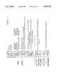
- FIG. 2illustrates, in simplified form, the flow of messages between various components of the network of FIG. 1 during establishment of an interactive broadband communication session.
- FIGS. 2A to 2Millustrate various displays generated in response to instructions from the Level 1 Gateway during broadband call processing.
- FIG. 3is a block diagram of one example of an alternate network architecture utilizing a Level 1 Gateway, in accord with the present invention.
- FIG. 4illustrates a hybrid fiber coax network architecture incorporating the Level 1 Gateway of the present invention.
- FIG. 5presents a high-level overview of the control functions of a network of the type shown in FIG. 4 and delineates those functions performed by the Level 1 Gateway from those performed by other network components.
- the Level 1 Gateway of the present inventionis useable in a variety of different broadband distribution networks which offer subscriber's selective communication with a plurality of broadband or video information service providers.
- FIG. 1depicts one such network, referred to as a Video Dial Tone Network, which is a direct improvement over the network disclosed in the above cited Litteral et al. Patent.
- a Video Dial Tone Networka direct improvement over the network disclosed in the above cited Litteral et al. Patent.
- an overview of the Video Dial Tone networkis set forth below, followed by a more detailed description of the functions of the Level 1 Gateway in that network. Two other examples of alternate networks utilizing the Level 1 Gateway will also be discussed.
- FIG. 1is a block diagram an exemplary broadband network for providing interactive services, such as video on demand, home shopping or purchasing, home banking, medical information, ticket ordering, gaming, etc.
- the customer premises equipmentCPE
- CPEcustomer premises equipment
- POTStelephone
- the connections to the central officeutilize Asymmetrical Digital Subscriber Line (ADSL) technology, typically over twisted wire pair, similar to that disclosed in the above cited Litteral et al. Patent.
- the ADSL connectionprovides a 1.5 mbits/s downstream video information channel, a two-way telephone connection and a two-way 16 kbits/s control channel.
- the illustrated Video Dial Tone network architecturemay use some form of fiber extension in the actual subscriber loops, to provide services to subscribers located more than 1.5 kilo-feet from a central office (see e.g. U.S. patent application Ser. No. 08/233,579, in the name of Bruce Kostreski, filed Apr. 26, 1994 and entitled "Extended Range Video On Demand System").
- the drop to the subscriber's premisesis always a wired ADSL loop.
- the network interface module in the DET 100connects to an ADSL multiplexer/demultiplexer 201 similar to the in-home ADSL unit in the above discussed Litteral et al. Patent.
- the connection between the network interface module of the DET 100 and the in-home ADSL unit 201may consist of an RJ48C line and connectors.
- Such a linkcomprises six wire pairs, two for the broadband data, two for upstream signaling and two for downstream signaling.
- Each ADSL subscriber line 203will connect to an ADSL bay 205 located in or associated with the subscriber's local central office.
- the ADSL bay 205includes an ADSL multiplexer/demultiplexer similar to the central office ADSL unit in the above discussed Litteral et al. Patent.
- the ADSL bay 205provides transport for voice signals on the subscriber loop to and from the associated voice switch 207.
- the ADSL bay 205also connects to an access concentrator 209 for providing two-way signaling connections through an X.25 type packet switched data network 211.
- the ADSL bay 205also receives broadband digital signals for downstream transport over the ADSL line 203 to each subscriber's premises from a digital cross connect switch 213, labelled "Access DCS" in the drawing.
- One ADSL line 203 to the homecarries one channel of video programming and provides a single output channel.
- the output channelcan provide a video signal to a VCR (not shown) or to the TV set 100'.
- the various Access DCS switches throughout the networkare controlled by switch controller 212.
- the ADSL bay 205connects to the Access DCS 213 via an appropriate number of local DS1 connections 215.
- the ADSL baywill be located in a remote central office facility.
- Such a remote ADSL bayconnects to the Access DCS 213 via a SONET type optical fiber link 217 providing an appropriate number of multiplexed channels to service the number of subscribers connected to the particular ADSL bay.
- Video Information service Providersmay access the downstream broadband portion of the system at a hub location (not shown) within a given LATA.
- the hubwill not perform any switching.
- High capacity optical fiber linksare aggregated at the hub to provide each VIP with a number of connections (e.g. one or more OC-3 links) from their respective video server to each Access DCS within the LATA.
- the Access DCS 213provides both point-to-point connections and point-to-multipoint connections.
- Individualized interactive servicessuch as Video On Demand, home shopping/purchasing and banking, use point-to-point connections wherein the Access DCS connects one broadband input port from a VIP's server to one output port going to the subscriber's ADSL line.
- Narrowcast and broadcast servicesutilize point-to-multi-point connections of one input port to a plurality of output ports.
- the illustrated architecture of the Video Dial Tone networkutilizes two levels of gateways, both of which will communicate with subscribers' DET's via the X.25 data network 211 and the signaling channel on the ADSL subscriber loops 203.
- the Level 1 Gateway 221performs a variety of network connectivity related functions, including communications port management of transmissions of information between subscribers and servers, processing of billing information and session management. Normally, each subscriber accesses the Level 1 Gateway (e.g. to select and access a particular VIP's server) by operation of a remote control device which causes the subscriber's DET 100 to transmit data signals to the Level 1 Gateway via the 16 kbits/s control channel and the X.25 packet switched data network 211. The Level 1 Gateway transmits one or more selection menus to the subscriber's DET 100 as screens of text data carried by the same path back through the network.
- the Level 1 Gatewaytransmits one or more selection menus to the subscriber's DET 100 as screens of text data carried by the same path back through the network.
- text or graphics information from the Level 1 Gatewayis displayed as a page of data.
- the text or graphics datacould be overlaid on a video display received through the broadband network, e.g. over one of the broadcast channels carried through the more advanced networks discussed below.
- the userwould turn on the DET terminal 100, and in response to data signals from the Level 1 Gateway 221, the terminal would display an initial selection menu.
- the subscriberwould input a selection, and in response to an appropriate data signal from the DET 100, the Level 1 Gateway 221 would instruct the various network components to set up a virtual circuit to the level 2 gateway of a selected VIP for signaling purposes and a direct downstream path from the VIP's server through the digital cross-connect switch 213 for video transmission.
- the Level 1 Gateway 221accumulates usage statistics relating to the broadband communication links through the network and supplies those statistics to a billing system, e.g. to a carrier access billing system (CABS) 227 as shown in FIG. 1.
- CABScarrier access billing system
- the Level 1 Gateway 221also exchanges various network operational status information with the switch controller 212 and with a video provider service center (VPSC) 231.
- VPSCvideo provider service center
- Level 1 Gatewayfunctions
- a level 2 gatewayprovides a number of services for the Information Providers. These services include transmission of menus of available information to subscribers, searches of available information, targeted advertisement insertion, previews, trailers, etc.
- the level 2 gatewaywill download video or audio menus to each subscriber's DET for display, thereby allowing each subscriber to select desired information. Once a subscriber makes a selection, the level 2 gateway will signal the appropriate server to schedule transmission of the selected information through the established downstream video transmission path.
- the Level 1 Gatewayaccumulates connectivity charge information for purposes of billing each called VIP.
- the level 2 gatewayrecords transactions, e.g. movies viewed, by each subscriber for billing purposes.
- the level 2 gatewayalso interacts with the DET 100 and controls the associated servers to download executable program code for storage in the DET system memory.
- the switch controller 212monitors operations of the digital cross connect switches 213 and provides appropriate information to the Level 1 Gateway. For example, if the switch controller 212 indicates that a broadband communication link through one of the switches has failed for some reason, the Level 1 Gateway will terminate its accumulation of usage data for billing for the particular broadband session.
- the video provider service center (VPSC) 231performs a related monitoring function with regard to the ADSL loops.
- the ADSL bays 205monitor communications over the subscriber lines 203 by periodically enquiring as to the status of each on-premise ADSL unit 201.
- the ADSL bays 205in turn inform the video provider service center (VPSC) 231 of any detected failures via data connections to that center (only one such data connection is illustrated in FIG. 1).
- the service center (VPSC) 231is manned operations support personnel.
- the center 231provides a display for review by one of the technicians.
- a VIPmay also call in and indicate that the VIP's system 252 has detected some form of failure.
- the techniciandecides whether in fact a failure has occurred. If so, the technician initiates an X.25 data call and transmission of a message from the video provider service center (VPSC) 231 to the Level 1 Gateway 221 identifying the failed link and instructing the Gateway 221 to tear down the particular broadband link.
- the Level 1 Gateway 221terminates its accumulation of usage time data for that link and instructs the switch controller 212 to tear down the link.
- personnel at the centercan initiate action to correct the fault. For example, if the switch controller 212 reports a fault in a particular switch 213, the personnel at the service center (VPSC) 231 can call a technician at the central office housing that switch and have that technician test the switch and correct any faults actually discovered. Similarly, if an ADSL bay 205 reports some fault on the twisted wire pair 203 or loss of communications with the on-premises ADSL unit 201, the personnel at the service center (VPSC) 231 can dispatch a repair technician to locate and correct the fault on the line or in the on-premises unit.
- the function of the video provider service center (VPSC) 231be fully automated to instruct the Level 1 Gateway 221 to stop billing data accumulation and tear down faulty broadband links without human intervention.
- the Video Dial Tone network of FIG. 1provides video on demand and other broadband interactive multimedia services offered by a plurality of service providers. For example, using the upstream data channel, the subscriber can send a request for a particular movie from his VIP of choice, and the VIP's server will retrieve and transmit that movie as an MPEG digital data stream on the 1.5 Mbits/s downstream channel to the digital audio/video processor in the subscriber's DET 100.
- MPEGmoving picture experts group
- MPEG 2is a second generation compression standard for packetized transport of one or more compressed video program signals in a single stream.
- a number of specific compression algorithmswill satisfy MPEG requirements.
- MPEGpermits encoding of audio/video program materials into digitized, compressed format at rates in the range of 1.5 to 6 Mbits/sec.
- the DET 100includes a CPU, comprising a 386 or 486 microprocessor and associated memory (RAM, ROE and EPROM) and an audio/video decoder, controlled by the CPU.
- the audio/video decoderdecompresses the digitized broadband information.
- the preferred embodiment of the audio/video decodercomprises an MPEG video decoder, an MPEG audio decoder, and an MPEG demultiplexer for selectively routing MPEG encoded video and audio packets carried on the digital broadband channel to the MPEG video decoder and the MPEG audio decoder, respectively.
- the DETalso includes a graphics display generator for generating displays of received text data, such as the initial turn-on selection menu, discussed in more detail below.
- the DETalso includes digital to analog converters and appropriate drivers to produce output signals compatible with a conventional television set from the decoded audio/video information and the graphics display.
- Each DETalso includes means to receive selection signals from a user and transmit appropriate data signals over a narrowband channel through the particular video network.
- the digital entertainment terminal (DET) 100is a programmable device to which different individual video information providers (VIP's) can download different applications software. At least one VIP, typically a vendor of the DET, also can download portions of the operating system.
- VIPtypically a vendor of the DET
- the DETwill permanently store only an operating system and a loader program, to control initial communications with a Level 1 Gateway or to facilitate initialization into a simplified CATV type mode of operation.
- the Level 1 Gatewayis a mini-computer, and in the Video Dial Tone network of FIG. 1, that computer would have interfaces for X.25 packet data communications.
- the Level 1 Gatewayis a UNIX based machine, such as a Tandem Integrity type computer.
- the Level 1 Gatewaycomprises a processor CPU, with associated RAM and ROM, as well as mass data storage and retrieval means, e.g. various disc drives.
- FIG. 2provides a somewhat simplified illustration of the process flow, with particular emphasis on the exchange of signals involved in setting up, carrying on and tearing down an interactive broadband session between a DET and a selected VIP's equipment.
- the customerturns on the digital entertainment terminal (DET) 100.
- the DETtransmits an "offhook" message upstream to the Level 1 Gateway servicing that DET.
- the DET type terminaltransmits an X.25 message through the upstream signal path to the access concentrator 209. This is a generic off-hook message, and the message from the terminal 100 carries no addressing.
- the access concentrator 209identifies the off-hook DET 100 by identifying the physical ADSL port on the access concentrator through which it received the message and assigns a signalling address to that terminal.
- the access concentrator 209populates the correct X.121 address for the sender into the call request message and populates the correct X.121 address for the Level 1 Gateway 221 into the message.
- the access concentrator 209sends the addressed message through the X.25 packet switched network 211 to the Level 1 Gateway 221.
- the callis terminated in the Level 1 Gateway 221 as an X.25 data call, and a two-way virtual circuit is dedicated to data communications between the Gateway 221 and the DET 100 for the duration of the call set-up processing.
- the X.121 addressesare used for call set.
- an available X.25 virtual circuitis defined for data flow in both directions, and subsequent packet transmissions will utilize appropriate packet headers to follow that virtual circuit node-to-node through the X.25 packet network.
- the Level 1 Gateway 221includes a file for each subscriber containing the subscriber's billing telephone number, the subscriber's X.121 address for signaling purposes, and the port identification of the broadband connection of the subscriber's line to the digital cross-connect switch (DCS) 213 serving the particular subscriber.
- DCSdigital cross-connect switch
- the Level 1 Gateway 221receives the addressed message from the access concentrator 209, that Gateway uses the X.121 address of the caller to check its internal database to determine if the caller is a valid video dial tone customer (S2). If the caller is not a valid customer, the system tears downs the session (S2 1 ).
- the Level 1 Gatewaywill typically transmit an instruction to the DET 100 to display some service denial message, such as that shown in FIG. 2A, as part of the operations to terminal communications with the particular DET. If the caller is a valid customer, the Level 1 Gateway 221 transmits an X.25 call accept message back to the DET 100 (S2 2 ) and waits for the first application level message.
- the set-top terminal DET 100sends an initiation message that says "hello” (S3).
- This "hello” messageincludes basic information such as a customer premises equipment (CPE) identifier and a CPE type designation of the particular DET. This information is primarily for the level 2 gateway.
- the Level 1 Gateway 221normally transmits back menu information, as ASCII data in X.25 message form (S4). The menu gives the customer the option to ask for a particular video information provider (VIP), such as the VIP operating the system 252.
- VIPvideo information provider
- each VIPprovides a level 2 gateway and some form of broadband information server 252 connected to the network.
- Each level 2 gatewayis assigned a 4-digit code.
- Some DET'swill have the option of preassigning a 4-digit VIP code, so that such a terminal always automatically transmits the preassigned 4 digit VIP code immediately with the initial "hello" message. Inclusion of the 4 digit VIP code in the initial message indicates the subscriber's VIP preference. As a result, the customer could always go to the same preferred VIP, and the customer need never see a VIP selection menu.
- the Level 1 Gateway 221checks the validity of the VIP code. Assuming the VIP code is valid, the Gateway 221 would see that this call is from a valid customer and initiate signaling communication with the particular VIP's level 2 gateway immediately.
- the Gateway 221If the Level 1 Gateway 221 detects that a received VIP preference code was not a valid VIP identifier code, the Gateway 221 transmits a message to the DET 100 through the signaling channel instructing the DET to display the notice shown in FIG. 2B. As shown in that drawing, the displayed notice informs the customer that the video provider preference was not recognized. The notice also informs the subscriber that a VIP selection menu will be forth coming. The Level 1 Gateway will wait for some finite period to permit the subscriber to review the displayed notice and then proceed with call processing as if a standard "hello" message had been received (without any VIP preference code), as discussed in more detail below.
- the DET and/or remote control associated therewithwill have appropriate keys to write a VIP preference into the memory of the DET 100.
- the DET 100 and/or remote controlwill also have a key or keys for input of an instruction to override the preprogrammed VIP preference. If the subscriber overrides the preference, the DET 100 will issue a normal "hello" message without the VIP identifier code, and processing will advance as if a standard "hello" message had been received (without any VIP preference code), as discussed below.
- Level 1 Gateway 221sends a banner followed a few seconds thereafter by a menu, through the downstream signaling channel (34).
- the banner display(FIG. 2C) depicts an initial greeting, such as "Welcome to Bell Atlantic Video Dial Tone Services".
- the menuis a screen of text and/or graphic images listing VIP's available to this customer.
- FIG. 2Dshows the format of the menu display. As shown, the menu displays the number of available providers (VIP's), lists each provider by two-digit code, and gives the name of each provider.
- the banner and first menu pagecan be combined into one display page requiring only a single transmission by the Level 1 Gateway.
- the bannermay be eliminated.
- One line of the menu pagecan indicate that the menu includes additional pages and what keys to actuate to request the next page from the Level 1 Gateway. If a customer selects an additional VIP menu page, the DET 100 transmits an appropriate request message to the Level 1 Gateway 221, and that Gateway transmits back another page of data for display.
- the remote control or keypad input on the set-top terminalhas arrow keys which allow the user to select from the VIP's listed on the visually displayed menu.
- the subscriberreviews the menu on their television set, and operates the arrow keys to move a cursor across the menu to an appropriate point on the screen, after which the user presses an ⁇ ENTER> key on the keypad or remote control.
- the usercan enter the two digits shown in the VIP's listing beside the name and then press ⁇ ENTER>.
- the DET 100transmits an appropriate data signal upstream through the network to the Level 1 Gateway 221 (S4).
- Level 1 GatewayWhen the Level 1 Gateway sends the selection menu to the set-top terminal, if no response is received from the DET 100 within a predetermined period, the Level 1 Gateway tears down the X.25 signaling link to that terminal. As discussed in more detail below, the Level 1 Gateway 221 will normally receive the selection input message from the DET 100 within the predetermined period and will translate that message into the 4 digit code for the selected VIP's level 2 gateway.
- the VIP menuis created as a function of which VIP's have access to each access digital cross-connect switch (DCS).
- DCSdigital cross-connect switch
- the video dial tone networkuses a number of DCS's serving different geographical areas and different subscribers.
- the DCS'swill typically be in different central offices. Not all VIP's connect to and provide services through all of the DCS's.
- a subscriberaccesses the Level 1 Gateway 221, that Gateway knows which DCS services that subscriber and which VIP's have server ports on that DCS.
- the Level 1 Gateway 221therefore limits the VIP's listed on the menu sent to the subscriber's DET 100 to those VIP's providing services through the particular DCS.
- the information on the menu that pertains to the various available providersis kept alphabetically.
- the Level 1 Gateway 221may randomly rearrange the order of the VIP listings in the menu on some periodic basis.
- the present inventionalso permits the customer to modify the menu to their own personal tastes.
- the Level 1 Gatewayrecognizes the customer's DET and transmits a customized menu listing only those three to the customer's DET terminal for display.
- the usertypically reviews the menu displayed on the TV screen and selects one of the available VIP's.
- the user's DET 100transmits a signal identifying the number of the selection from the menu upstream to the Level 1 Gateway 221 (S5).
- the Level 1 Gatewayalways knows what menu it sent to the particular DET.
- the Level 1 Gateway 221uses the precise menu information and a table of VIP identifier codes to translate the selection input signal from the DET 100 into an actual 4-digit VIP identification address for the level 2 gateway of the particular VIP that the person selected.
- the Level 1 Gateway 221sends an X.25 message to the DET 100 saying please wait while we connect to the VIP's system 252 (S6).
- the DETproduces a standby display, such as the display shown in FIG. 2E.
- the displaypreferably will identify the VIP that the customer is awaiting connection to.
- the row of ⁇ Q ⁇ s in FIG. 2Eindicate the display space in which the VIP's name is inserted
- the Level 1 Gateway 221next goes over a locked up "permanent" virtual circuit through the X.25 network, to communicate with the level 2 gateway of the VIP's system 252. Specifically, the Level 1 Gateway 221 contacts the level 2 gateway and indicates, through a standard message, that it has a customer calling (S7). The Level 1 Gateway 221 identifies the customer to the level 2 gateway by sending the standard billing telephone number for the calling customer to the level 2 gateway. The CPE identification information and the CPE-type information for the DET 100 that was sent in the initial origination message is also sent to the level 2 gateway (VIP) at this time. The VIP's level 2 gateway may accept or reject the call (S8) after receiving the initial request indicating a customer is available.
- Level 1 Gateway 221When the Level 1 Gateway 221 initially asks the level 2 gateway if a calling subscriber is a valid customer, the Level 1 Gateway expects a response accepting or rejecting the call within a set time, and if the response is not received in that time, the Level 1 Gateway sets off an appropriate alarm.
- the Level 1 Gateway 221would inform the DET 100 of the inability to reach the selected VIP and instruct the DET to provide an appropriate display through the TV100' to the user.
- the displaymight inform the user that there is some form of network problem and either instruct the user to try again later (FIG. 2F) or to select another provider (FIG. 2G), depending on whether other providers are available as indicated on the VIP selection menu presented to this subscriber.
- the Gateway 221could use one of the provider--unavailable message of FIGS. 2H and 2I.
- the level 2 gatewaymay reject the call for a number of reasons. For example, that gateway may look up the caller's telephone number in a list of the VIP's subscribers' telephone numbers to determine if the caller in fact subscribes to the VIP's services. The level 2 gateway may also check on the calling subscriber's current billing/payment status. Non-subscribers and/or subscribers who are delinquent in paying their bills to the rIP would be rejected. The level 2 gateway might also reject a call if all its existing server output ports on the DCS 213 serving the particular subscriber are currently in use. If the level 2 gateway decides to reject a call, that gateway sends a message back to the Level 1 Gateway 221 indicating a rejection of the call (S8 1 ).
- the rejection messageindicates the reason for the rejection.
- the Level 1 Gateway 221transmits a message to the DET 100 instructing that terminal to display an appropriate one of the notices shown in FIGS. 2H through 2L as a call rejection notice on the associated TV 100' (S8 2 ).
- the specific rejection notice displayed to the calling subscriberdepends on the circumstances of the particular call rejection. If the provider can not service the broadband call at this time because of some server failure, the message would indicate to the user that the provider is not available. If no other providers are available to the particular caller, the message would suggest that the caller try again later, as in FIG. 2H. Alternatively, if the caller has access to other providers the message would suggest that the caller select another provider, as shown in FIG. 2I. If all of the selected the provider's server ports are busy, the Level 1 Gateway would instruct the DET 100 to display one of the busy notices shown in FIGS. 2J and 2K, depending on whether or not other providers are available to the particular caller. If the VIP arbitrarily denies access, e.g. because the caller is not a recognized subscriber or has not paid her bill, then the Level 1 Gateway would instruct the DET 100 to display a call denial message, such as shown in FIG. 2L.
- the level 2 gatewayaccepts the call, provides a server output port and gives an identification for that port to the Level 1 Gateway 221 (S8 3 ).
- the Level 1 Gateway 221transmits the X.121 address of the calling customer to the level 2 gateway (S9).
- the Level 1 Gateway 221looks in its internal record to find the broadband port number for the requesting customer and sends a message to the switch controller 212 instructing one of the DCS's 213 to connect the server port the VIP provided to the broadband port for the subscriber, to thereby set up the broadband communication link (S12).
- the level 2 gatewayuses the customer's X.121 and its own X.121 address to initiate a new X.25 signaling communication type call to the subscriber's DET 100 (S11).
- the switch controller 212transmits back an indication that the broadband connection has been established. Then the Level 1 Gateway 221 tears down its own X.25 signaling connection with the subscriber's DET 100. At that time, the Level 1 Gateway 221 informs the level 2 gateway that it has set up a good broadband link, and the Level 1 Gateway 221 initiates a billing record for the call. An interactive broadband session ensues via the broadband and signaling links.
- the controller 212informs the Level 1 Gateway 221 of that fact and the specific reason it could not establish the broadband link.
- the Level 1 Gatewaypasses that information on to the level 2 gateway.
- the codes identifying the basis for the failure to complete the broadband callprovide the level 2 gateway information as to whether the failure is a one time condition or is continuous, whether or not the failure is network-wide, etc. This information is useful to the operator of the level 2 gateway, for example, to determine whether to continue to send requests for broadband channels through the Level 1 Gateway or to suspend operations until receiving notice that a network fault has been cleared.
- the level 1 Gateway 221also provides an appropriate message through the signaling channel for display by the DET 100 informing the customer. The displayed message might offer the customer the option to select another VIP if the fault relates only to accessing the selected VIP (similar to FIG. 2I), and if the customer does so, the call processing begins again with transmission and display of the VIP selection menu.
- the level 2 gatewayinstructs the Level 1 Gateway 221 to tear down the broadband session connection (S14).
- the instructionincludes the customer's billing telephone number and the server port identification for the VIP port used for the broadband communication.
- the Level 1 Gateway 221stops the billing timing for that broadband session and transmits an instruction through the switch controller 212 to the DCS 213 to tear down the broadband connection between the server port and the customer's broadband port (S15).
- the port identificationsare always ten-digit numbers. Of the digits, the second, third and forth digit positions identify the digital cross-connect switch (DCS) in question.
- DCSdigital cross-connect switch
- the Level 1 Gatewaycompares the second, third and fourth digits to the corresponding digits of the subscriber's port identification to determine if the server port is in fact on the same digital cross-connect switch as the subscriber's port. If the digits do not match as they should, the Level 1 Gateway informs the level 2 gateway of the error and requests a new server port identification.
- the Level 1 Gateway 221creates a log record that contains specific information including the time that the Level 1 Gateway received or sent each message. Information of a failure is furnished by the switch controller 212. The switch controller will indicate between which ports the failure occurs. The Level 1 Gateway then notifies level 2 gateway and possibly the set-top terminal that a network failure has occurred and the communication link is lost.
- the Level 1 Gatewaycollects usage statistics for billing purposes.
- the VIP'smay choose to collect audience statistics through the level 2 gateways.
- the subscribermay be charged a flat monthly charge, e.g. on her telephone bill, for video dial tone service.
- the usage sensitive charges for the broadband connections through the networkgo to the VIP's.
- an alternate implementation of the present inventioncombines network usage charges with VIP's service charges into a single bill to be sent directly to each subscriber.
- the Level 1 Gatewaycreates a billing record for each call which resulted in an actual broadband connection through one of the digital cross-connect switches (DCS's).
- the billing recordidentifies the level 2 gateway, by its 4-digit code.
- the billing recordincludes an identification of the customer by billing telephone number, the type of call (e.g. ADSL or fiber), an identifier of the digital cross connect switch (DCS) which provided the broadband connection, an identifier of the particular Level 1 Gateway that serviced the call, the connect date, the time that the broadband connection was first established, and the elapsed time until tear-down of the broadband link.
- the type of calle.g. ADSL or fiber
- DCSdigital cross connect switch
- the Level 1 Gatewaysupplies all of this information directly through a transmission link to the telephone company's carrier access billing system (CABS) 227 for processing into appropriate invoices for billing the VIP, in a manner substantially similar to billing of an Interexchange Carrier.
- the usage datacan be downloaded periodically to the CABS 227, or the Level 1 Gateway may initiate downloading in response to a manual request from the system administrator.
- Each VIPestablishes its own rates and procedures for actually billing the end users.
- the Level 1. Gateway and CABS systemsmay also accumulate data and bill the VIP's for the X.25 signaling links, but in the current implementation there would not be any separate charges for the various X.25 signaling communications.
- the video dial tone networkessentially bills the VIP for the broadband connection time, and each VIP in turn bills its subscribers.
- the Level 1 Gateway 212can supply the broadband usage information to a customer record information system or ⁇ CRIS ⁇ (not shown).
- CRISwould store information as to each VIP's service charges and would process that information together with the usage data from the Level 1 Gateway to generate a combined bill for the end user/subscriber.
- the subscriberwould pay the billed amount to the network operations company, typically the local telephone company, and the network operations company would divide the received revenues between itself and the VIP(s).
- the userinitiates a sign-off procedure with the first VIP.
- the first VIP's level 2 gatewayinstructs the Level 1 Gateway 221 to tear down the broadband link, as discussed above, and the DET 100 initiates a new VIP selection procedure with the Level 1 Gateway in a manner similar to the initial turn-on communication discussed above.
- the DETwill send some form of "terminate" message through the signaling link to the level 2 gateway.
- the level 2 gatewaywould instruct the Level 1 Gateway 221 to tear down the broadband connection and stop billing in the above discussed manner.
- the subscriberturns the DET 100 back on, that terminal begins a new communication with the Level 1 Gateway 221 in the normal manner.
- the Level 1 Gatewaywill discover this fact at the time it instructs the switch controller 212 to set up the second connection to the newly selected VIP. At that time, the Level 1 Gateway 221 will instruct the switch controller 212 to tear down the first connection and set up the second connection.
- the Level 1 Gatewayalso offers a personal identification number (PIN) control functionality. This gives the end user the ability to assign a PIN number to one or more of the VIP's shown on the VIP selection menu. For example, certain VIP's might show materials which a parent might deem unsuitable for young children to view. Such a parent would assign a PIN to those VIP's.
- PINpersonal identification number
- the Level 1 Gateway 221would instruct the DET 100 to output a prompting type display and/or audio message requesting input of the PIN. The parent would know the PIN and be able input the correct PIN, using the DET remote control, to access the VIP. However, a child not knowing the PIN would not be able to give the correct response to the prompt, and the Level 1 Gateway 221 would deny access.
- the initial menu from the Level 1 Gatewaywill offer callers the ability to interact with that Gateway to control their video dial tone service.
- the subscriberwould initiate communications with the Level 1 Gateway in precisely the same manner as for a call to a video information provider (VIP), as discussed above with regard to FIG. 2.
- VIPvideo information provider
- one or more of the VIP listing lineswould identify Level 1 Gateway interactions, e.g. for "Personal Options". Selection of one such choice from the menu initiates an interactive session between the subscriber and the Level 1 Gateway. In the network of FIG. 1, the communications for this session will be entirely through the signaling channel.
- the DET 100transmits upstream signals through the signaling link and the X.25 data call to the Level 1 Gateway 221, and the Gateway 221 transmits text or graphics displays and instructions to the DET 100 back downstream through that signaling path.
- the Level 1 Gatewaywould have broadband communication capabilities.
- a "Personal Options" session with the Level 1 Gatewaywould step the subscriber through a series of menus and inputs to select an option to modify (e.g. PIN number or customize menu) and collect the information from the subscriber needed to execute that option. For example, if the subscriber selected the PIN number option, the Level 1 Gateway would ask for a four digit PIN number input from the subscriber and then ask which VIP's on the menu the subscriber wanted that PIN applied to. The currently preferred implementation offers only a single PIN for all VIP's a subscriber chooses to restrict access to. Alternatively, the Level 1 Gateway could offer to apply different PIN numbers to different VIP's. A similar procedure permits a subscriber to set up a short list of VIP's that subscriber prefers.
- an option to modifye.g. PIN number or customize menu
- the "Personal Options" through the Level 1 Gateway 221are limited to PIN number and menu customization.
- this Level 1 Gateway featurewould allow the subscriber to set up and modify a wider variety of service options.
- the Level 1 Gatewaymight offer a subscriber an option to specify or change a level of broadcast service.
- the Level 1 Gatewaymight offer a subscriber an "Hours of Service" control. If the subscriber selects this option, the Gateway would ask for input of a number for use as a threshold value.
- the Level 1 GatewayFor each week (or other specified time interval), the Level 1 Gateway would monitor the number of hours of service provided to that subscriber's DET(s) and would terminate service to that subscriber's DET(s) if usage exceeded the threshold number input by the subscriber.
- This service time limitationmight have an attendant PIN number based override to permit some member of the household (typically a parent) to override the hours of service limitation.
- the Level 1 Gatewaycould similarly offer subscribers the option to specify time of day/week limitations and then would deny service at other times unless a valid PIN number was received.
- the Level 1 Gatewaymay receive an indication from the switch controller 212 that it can not establish a desired broadband connection.
- the controller 212monitors operations of the individual DCS switches 213 at all times and will also inform the Level 1 Gateway upon detection of a fault or interruption in an established broadband connection.
- the level 1 Gateway 221transmits notice of an inability to establish a desired broadband session to the requesting DET, using notices such as shown in FIG. 2F and 2G depending on whether or not other VIP's are available to the particular subscriber at the time of the call. If the Level 1 Gateway 221 receives notice of a fault in an already established session, the Gateway 221 stops accumulating billing data for that session and transmits an X.25 message regarding the failure to the VIP's level 2 gateway.
- the level 2 gatewaymay provide an appropriate notice to the subscriber through the signaling link, if that portion of the session is still operative.
- the Level 1 Gatewaymay initiate a new X.25 call to the subscriber's DET 100 to provide an appropriate display notice.
- the VPSC 231monitors the operations of ADSL communications capabilities on each subscriber's line. If the VPSC 231 detects a fault in a line currently engaged in a broadband communication session, and the technician at the center 231 determines that the fault is real, then the VPSC 231 makes an X.25 call to the Level 1 Gateway 221 and sends an error message identifying the line to the Level 1 Gateway 221. The Gateway 221 stops accumulating billing data for that session and transmits a message to the switch controller 212 to tear down the session. Once the switch controller 212 provides a positive acknowledgement to the Level 1 Gateway 221 that the session has been torn down, the Gateway 221 provides a confirmation message to the VPSC 231.
- the Level 1 Gatewayalso transmits an X.25 message regarding the failure to the VIP's level 2 gateway.
- the level 2 gatewaymay provide an appropriate notice to the subscriber through the signaling link, if that portion of the session is still operative. However, in the preferred embodiment, the level 2 gateway terminates its X.25 call to the DET 100, and the Level 1 Gateway initiates a new X.25 call to the subscriber's DET 100 to provide an appropriate display notice regarding the line failure. If the problem was line related, a network problem type display notice, such as shown in FIG. 2F, could be used. If the fault report suggested some defect in the DET or broadband communications from the ADSL unit 201 to the DET 100, the Level 1 Gateway 221 would specify a display notice relating to the DET itself, such as that shown in FIG. 2M.
- the Level 1 Gateway 221can also initiate an audit of the status of a subscriber's line.
- the Level 1 Gatewayissues an audit request for the subscriber line to the switch controller 212.
- the switch controller 212determines the status of the subscriber's line and informs Level 1 Gateway whether the line is in service but idle, in service and in progress, or out of service and idle.
- the Level 1 Gateway 221can initiate an audit of the status of a source line from a server.
- the Level 1 Gatewayissues an audit request for the server line to the switch controller 212.
- the switch controller 212determines the status of the source or server line and informs Level 1 Gateway. For example, if the server line is operative but not involved in a connection, the reported connection status of the server line is "in service but idle".
- Level 1 Gateway 221instructs the switch controller 212 to establish a broadband connection
- the Gateway 212expects a response from the controller 212 within a predetermined time interval. If the controller 212 does not respond within the predetermined time interval, the Level 1 Gateway 221 will send an ABORT message to the switch controller 212 to cancel the session establishment message.
- the Level 1 Gateway 221also informs the level 2 gateway of the failure to establish a connection and provides an appropriate notice of the failure to the subscriber through the X.25 signaling call still existent with the DET 100.
- the Gateway 221will also record the failure in an alarm file.
- the Gateway 212When the Level 1 Gateway 221 instructs the switch controller 212 to tear down a broadband connection, the Gateway 212 expects a response from the controller 212 within a predetermined time interval. If the controller 212 does not respond within the predetermined time interval, the Level 1 Gateway 221 will send an ABORT message to the switch controller 212 to cancel the original session establishment message, and the Gateway 221 will also record the failure in an alarm file.
- Level 1 Gatewayin the cross-connect switched type Video Dial Tone network, however, that Gateway will work equally well in a variety of other video dial tone network architectures with enhanced capabilities.
- Adaptation of the Level 1 Gateway to other network architecturesprincipally requires only that, instead of interacting with a switch controller and digital cross-connect switches (DCS's), the Level 1 Gateway will interact with an asynchronous transfer mode (ATM) switch and some form of intermediate network control node, such as a Host Digital Terminal (HDT).
- ATMasynchronous transfer mode
- HDTHost Digital Terminal
- the Level 1 Gatewaymay also conduct signaling communications with the DET's and the level 2 gateways through the ATM switch instead of through the X.25 packet switched system used in the Video Dial Tone Network of FIG. 1.
- the principal functionalities of the Level 1 Gateway discussed above, however,will generally remain the same.
- FIG. 3depicts an example of one such advanced video dial tone network utilizing the Level 1 Gateway of the present invention.
- the illustrated networkutilizes an advanced fiber to the curb system with ATM (Asynchronous Transport Mode) transport, and is similar to one of the networks disclosed in commonly assigned application Ser. No. 08/250,792, filed May 27, 1994, entitled “Full Service Network” (attorney docket no. 680080), the disclosure of which is incorporated herein entirely by reference.
- the network of FIG. 3uses essentially a switched star type architecture.
- the Full Service Network illustrated in FIG. 3provides broadcast video distribution, archival video services and interactive multi-media services as well as a suite of narrowband services including plain old telephone service.
- the broadcast video serviceswill initiate from a broadcast type server, such as ATM video source 1101.
- the broadcast server source 1101includes an actual analog video source 1110. Although only one is shown, a typical broadcast service provider will have a plurality of such video sources in the same or separate server systems.
- the analog signal from the sourceis carried by any convenient means, such as an optical fiber, etc.
- Means(not shown) are provided as necessary to convert analog video transmission signals, e.g. NTSC broadcast signals, to baseband video and audio signals.
- the baseband signalsare applied to a real time encoder 1120.
- the real time encoder 1120digitizes the audio and video signals and performs data compression. As currently envisaged, the encoder will encode the program signal into an MPEG 2 format.
- the illustrated real time encoder 1120preferably is set up as a bank of encoders to process six sets of analog audio/video program signals in parallel.
- the bank of encoders 1110produces six 6 Mbits/sec MPEG 2 bit streams, which are combined together with appropriate overhead information into a single 45 Mbits/sec DS-3 type signal.
- the DS-3 signal from the encoder 1120is input to an interworking unit (IWU) 1130.
- the interworking unit 1130is the actual input point for the encoded broadcast video information into the Full Service Network of FIG. 3.
- the Full Service Networkuses asynchronous transfer mode (ATM) switching to transport all broadband or video information, including the broadcast video information.
- ATMis a packet oriented time division multiplexing technique.
- informationis organized into cells having a fixed length and format. Each cell includes a header, primarily for identifying cells relating to the same virtual connection, and an information field or "payload".
- a 53 octet ATM cellwould include a cell header consisting of 5 octets and a payload consisting of 48 octets of data.
- One MPEG 2 packetwould be mapped into payload data in four such ATM cells. Transfer is asynchronous in the sense that the recurrence of cells that contain information from any particular sender is not necessarily periodic.
- Each device using the ATM networksubmits a cell for transfer when they have a cell to send, not when they have an assigned or available transmission time slot.
- ATMallows any arbitrary information transfer rate up to the maximum supported by the ATM network, simply by transmitting cells more often as more bandwidth is needed.
- all video materialswill be transferred at a constant, standardized bit rate.
- Preferred later generations of the networkwill utilize the ATM capabilities of the network to permit transmission of video information over channels of different bit rates, e.g. 1.5 Mbits/sec, 3 Mbits/sec, 6 Mbits/sec, etc. It will also be possible to vary the bit rate during communication on an as needed basis.
- the interworking unit 1130grooms the continuous MPEG 2 bit streams of the broadcast services for ATM cell stream transmission over optical fiber transport links. For example, the interworking unit will divide the bit stream into appropriate length payloads and combine the payload data with appropriate cell headers, necessary for ATM transport. In an initial implementation, downstream links would carry an OC-12 bit rate, but higher rate transports such as OC-48 will be used in later implementations. Assuming use of OC-12, one such transport link will normally carry the equivalent of 112 DS-3's. However, conversion into ATM cell format with associated headers imposes added overhead requirements on the data transmissions. In the presently preferred embodiment, one interworking unit 1130 therefore processes up to ten DS-3 signals to produce an ATM bit stream at the OC-12 rate.
- a transport interface 1140converts the electrical signal from the interworking unit 1130 into an optical signal and transmits the optical signal through fiber 1150 to an adaptive digital multiplexer (ADM) identified in the drawing as a video bridging and insertion device 1160.
- ADMadaptive digital multiplexer
- the ADM 1160performs three functions, passive bridging, active bridging and insertion of signals from other broadcast service providers (if any). The three functions may actually be separate, but in the preferred embodiment, all three would be performed by elements collocated within the one network component ADM 1160.
- the real time encoders 1120each output a single DS-3 signal comprising up to 6 MPEG 2 bit streams.
- the interworking unit 1130processes up to ten DS-3 signals to produce an ATM bit stream at the OC-12 rate. Consequently, one broadcast video source 1101 may produce as many as 60 channels of CATV type broadcast programming for transport over one OC-12 type SONET optical fiber 1150. Many providers, however, may not choose to broadcast so many channels. For example, the provider operating broadcast video source 1101 may offer only 42 channels. Such an ATM channel transmission on the optical fiber 1150 will not utilize the entire OC-12 channel capacity of that fiber. In the specific example, the 42 channels together require the equivalent of 7 of the available 10 DS-3's.
- the illustrated architecturepermits a second broadcast service provider to utilize the transport capacity not used by the first provider.
- the second broadcast service providerwould offer additional channels from a separate second source 1101'.
- the source 1101'is essentially identical in structure and operation to the source 1101, but the source 1101' will offer up to the number of channels necessary to fill the OC-12 transport capacity. In the example, if the source 1101 transmits 42 channels (7 DS-3's) via the fiber 1150, the second source 1101' could transmit up to 18 additional channels (3 DS-3's).
- the function of the insertion device in the ADM 1160is to combine the signals from the two sources into a single OC-12 rate signal (10 DS-3's in ATM cell format) for further transmission through the optical network.
- the two bridging functionsfacilitate dissemination of the broadcast material throughout the entire Full Service Network.
- the passive bridging elementsare optical splitters for splitting one OC-12 optical signal from the insertion device into a number of duplicates thereof, e.g. 1:2, 1:4, 1:8, etc.
- the active bridging elementsconvert an optical signal to an electrical signal, regenerate the electrical signal and convert the regenerated signal back to an optical signal for application to multiple output ports.
- the optical OC-12 output signals from the bridging componentsare transmitted over a large number of optical fibers 1170 to host digital terminals throughout the network service area.
- the host data terminal (HDT) 1180is shown as a representative example.
- the digital entertainment terminal (DET) in the subscriber's homeprovides a signal identifying the selected channel to the HDT 1180.
- the signaling between the digital entertainment terminal (DET) and the HDT 1180will be discussed in more detail below.
- the ATM cell stream from an optical fiber 1170is applied to a bus.
- One HDTwill communicate with a large number of optical network unit (ONU's) 1210, two of which are shown.
- the HDTwill communicate with each ONU 1210 via a pair of optical fibers 1190.
- each home or living unitwill have as many as four DET's.
- Each ONU 1210 and the downstream fiber of the pair 1190 to the ONU 1210will provide downstream video services to a number of homes, e.g. 8 to 24.
- the transmissions on the downstream fibers between the HDT and the ONU's 1210are synchronous, although the video information remains in ATM cell format.
- Each DET served by an ONU 1210is assigned a specified time slot on the downstream fiber of a pair 1190.
- the HDT 1180includes a component which is essentially a non-blocking type ATM switch.
- the HDT 1180accesses the appropriate bus and identifies each ATM cell on that bus for which the header information indicates that the cell represents information for the selected broadcast channel.
- the identified ATM cellsare bridged by the ATM switch from the bus to a line card providing transmissions over the optical fiber 1190 to the particular ONU 1210 which services the requesting subscriber's premises.
- elements on the line card communicating with the particular ONUwill buffer the cell as necessary and place the cell in the time slot for that DET on the downstream fiber of optical fiber pair 1190.
- the cells selected for a particular DETtogether with cells going to other DET's served by the same ONU multiplexed into their respective time slots, are applied to an electrical to optical converter and transmitted over the downstream fiber to the ONU 1210 serving the particular subscriber's premises.
- the basic purpose of the ONUis to desegregate the HDT side links into individual customer links and provide optical to electrical conversion for electrical delivery to the individual subscribers' premises.
- the drop cable to each subscriber's premisescomprises a coaxial cable for carrying the video and/or two-way digital data signals and a twisted wire pair for carrying telephone signaling.
- ADSL communications over twisted wire paircould be used between the ONU and the subscribers premises.
- the ONUincludes means to convert optical signals received over the downstream fiber to electrical signals and transmit signals from each DET's assigned time slot down over the coaxial cable to the subscriber's premises.
- the ONUalso provides two-way conversion between optical and electrical signals for voice telephone service over the twisted wire pairs and for the signaling channels to/from the DET's.
- a power source 1211supplies -130V dc and battery reserve power for telephone service to the ONU's 1210.
- the power source 1211may connect to the ONU's via twisted pairs, but in the preferred embodiment, the power is carried over a coax distribution cable.
- the digital entertainment terminal (DET) 1217is a programmable device to which different applications programs and/or portions of the operating system will be downloaded from a gateway device in order to permit the DET to interact with different information service providers and thereby offer the user totally different types of services.
- the DETmay be similar to that used in the network of FIG. 1, with the exception that the network interface module within the DET 1217 provides the various broadband and signaling connections to a coaxial cable, instead of to an interface to an ADSL twisted wire pair type line, and the communication software within the DET is adapted to process ATM transported information.
- the DET 1217includes means (not shown) to demodulate received data and convert ATM cell stream data into bit stream data for further processing.
- the DET 1217also includes a digital signal processor to decompress received video signals as well as a graphics display generator for generating displays of text data, such as the initial turn-on selection menu.
- the DETwill also include a digital to analog converter and appropriate drivers to produce output signals compatible with a conventional television set.
- Each DET 1217also includes the means to receive selection signals from a user and transmit appropriate data signals over a narrowband channel on the coaxial drop cable to the ONU 1210.
- the ONUmultiplexes the user input data signals from the DET's it services together and transmits those signals to the HDT over an upstream fiber of the optical fiber pair 1190.
- the HDTtransmits the upstream control signals to control elements referred to as gateways.
- the HDT'scommunicate with the gateways through an X.25 type data network. Future implementations will use ATM communications for the signaling.
- the Level 1 Gateway 1230provides primary control of all routing and access functions of the network and accumulates various usage statistics, in a manner substantially similar to that of the Level 1 Gateway 221 in the network of FIG. 1.
- the control functionsinclude controlling access to broadcast programs by individual subscribers. Control of access to on demand programming and interactive multimedia services through a PVC controller 1420 and an ATM switch 1410 will be discussed in more detail below.
- the Level 1 Gatewayalso will transmit narrowband information to the DET 1217 instructing it to initiate display of various selection menus of available video information service providers.
- the Level 1 Gatewayconnects to a service administration module (SAM) which maintains a data base of video information service providers and customer profile data for the broadcast, archival and interactive video services available through the network. This data may include customized menus, pre-subscription information, identification of impulse pay per view events and premium channels, etc. Under different circumstances, the video information providers and/or the individual customers can access this data for provisioning.
- SAMservice administration module
- the Level 1 Gatewayalso connects to an operations support module (OSM).
- OSMoperations support module
- the operations support moduleprovides an interface to standard operating support systems used for additional network provisioning functions.
- the DET 1217transmits data upstream through the various network elements to the Level 1 Gateway identifying the selected channel.
- the Level 1 Gateway 1230accesses stored data regarding the broadcast services to which the customer currently subscribes. If the customer subscribes to the requested service, the Level 1 Gateway 1230 transmits an instruction to the HDT 1180 to route the cells for that channel to the subscriber's DET 1217 in the manner discussed above. If the customer is not currently a subscriber to that service, the Level 1 Gateway 1230 transmits a data message back to the DET 1217 instructing it to provide an appropriate television display, e.g. informing the customer of a service denial and/or asking the subscriber for appropriate inputs to initiate a new subscription.
- the above selection procedure through the Level 1 Gatewayprovides the Gateway 1230 with information as to each selection a subscriber makes and when the selection is made.
- the Level 1 Gatewayalso receives information as to when a DET session ends, e.g. upon turn-off of the DET or upon request for a session with a different provider.
- the Level 1 Gatewayhas all information necessary to accumulate a variety of statistics as to viewer usage both for billing purposes and for audience accounting purposes.
- certain relevant control datacould be downloaded to the HDT, either from the Gateway 1230 or from the service administration module (SAM).
- SAMservice administration module
- the broadcast VIP'swould provide provisioning data to the SAM, and the SAM periodically downloads that data to the appropriate HDT's, either directly or through the Level 1 Gateway 1230.
- the provisioning data downloaded to the HDT's 1180would include channel mapping information and subscriber authorization control information.
- the channel mapping informationspecifies what programs are carried on each ATM virtual circuit, within each DS-3, on each respective optical fiber 1170.
- the HDT 1180accesses the channel mapping information in response to each program selection by a subscriber to route the ATM cell stream to the requesting DET.
- the authorization control datawould indicate which program each subscriber is authorized to access, e.g. because that party has subscribed to the particular program service and is not delinquent in bill payments. When a subscriber requests a program, the HDT 1180 would check this data to determine whether or not to supply the program to the subscriber's DET 1217.
- the HDT 1180As the HDT 1180 routes selected channels to the DET's 1217, the HDT would accumulate usage data and/or pay per view event purchase data for the subscribers serviced thereby. The HDT 1180 would periodically upload such usage data to the Level 1 Gateway 1230 and/or to the SAM for subsequent transmission to appropriate billing systems of the network service provider or the VIP's, respectively.
- the network of FIG. 3offers subscribers access to other wideband services, such as video on demand and interactive multimedia services. Access to these additional broadband services is through an ATM switch 1410. As discussed in more detail below, the access through this switch is controlled by the Level 1 Gateway 1230 in a manner quite similar to the routing to a VIP in the network of FIG. 1.
- Each of the non-broadcast service providers 1400will have a level 2 gateway 1401 and some form of file server 1403.
- the video information provider's (VIP's) systemmay provide ATM cell stream outputs for transmission through the network.
- the network operatorwould supply an interworking unit similar to the unit 1130 discussed above to convert the provider's bit stream data into an ATM cell stream format compatible with the Full Service Network.
- the ATM switchtransmits selected ATM cells via optical fibers 1415 to the HDT's 1180.
- a PVC controller 1420stores data tables defining all possible virtual circuits through the ATM switch and the HDT's to each terminal of a customer subscribing to a particular provider's services. These data tables define the header information and the particular fiber output port used to route cells to the correct HDT and the time slot information on the downstream fiber to the appropriate ONU serving each DET. The data tables thus define "permanent virtual circuits" (PVC's) between the providers and the DET's.
- the subscriber's DET 1217When a subscriber initiates a session with a broadband interactive service provider, for example VIP 1400, the subscriber's DET 1217 provides an appropriate "off-hook" signal to the HDT 1180.
- the HDT 1180sends the message through the X.25 packet switched network to the Level 1 Gateway 1230.
- the Level 1 Gateway 1230receives the addressed message from the HDT, that Gateway uses the X.121 address of the caller included in the message to check its internal database to determine if the caller is a valid network customer. If the caller is not a valid customer, the system tears downs the session. If the caller is a valid customer, the Level 1 Gateway 1230 transmits an X.25 call accept message back to the terminal and waits for the first application level message.
- the DET 1217sends an initiation message that says "hello"
- This "hello” messageincludes basic information such as a customer premises equipment (CPE) identifier and a CPE type designation.
- the Level 1 Gateway 1230sends a menu and a banner through the downstream signaling channel, as in the earlier network embodiment.
- the menuis a screen of text listing VIP's available to this customer or the VIP's that the customer as previously selected for purposes of her customized menu presentation.
- the subscriberreviews the menu on their television set, and operates the arrow keys on the DET remote control to move a cursor across the menu to an appropriate point on the screen, after which the user presses an ⁇ ENTER> key on the keypad or remote control.
- the DET 1217transmits an appropriate data signal upstream through the network to the Level 1 Gateway 1230.
- the Level 1 Gatewaymay execute a PIN number access routine, as in the earlier embodiment, if the subscriber has previously requested such access control for selected ones of the VIP's. For simplicity here, it is assumed that the currently selected VIP is not subject to such a PIN number requirement.
- the Level 1 Gatewayis merely expecting to receive the VIP selection input from the DET within a predetermined period following the menu transmission. If the Level 1 Gateway receives the selection input message from the DET within the predetermined period, the Gateway 1230 translates that message into the 4 digit code for the selected VIP's level 2 gateway.
- the Level 1 Gatewaysends a message to the DET saying please wait while we connect to the VIP.
- the Level 1 Gatewaythen goes over the X.25 network to communicate with the selected VIP's level 2 gateway.
- the Level 1 Gateway 1230contacts the level 2 gateway 1401 and indicates that it has a customer calling.
- the Level 1 Gateway 1230identifies the customer to the level 2 gateway 1401 by sending the standard billing telephone number for the calling customer to the level 2 gateway.
- the CPE identification information and the CPE-type information that was sent in the initial origination messageis also sent to the level 2 gateway (VIP) at this time.
- the VIP's level 2 gatewaymay accept or reject the call after receiving the initial request indicating a customer is available, as in the network of FIG. 1. If the level 2 gateway 1402 sends a message back to the Level 1 Gateway 1230 indicating a rejection of the call, the Level 1 Gateway transmits a message to the DET 1217 instructing that terminal to display some form of call rejection notice on the associated TV.
- the level 2 gateway 1401accepts the call, provides a server output port and gives a port identification for the port on the server 1403 to the Level 1 Gateway 1230.
- the Level 1 Gatewaytransmits the X.121 address of the calling customer's DET 1217 to the level 2 gateway 1401.
- the level 2 gatewayuses that address to initiate a new signaling communication through the X.25 network 1220 with the subscriber's set-top terminal DET 1217.
- the Level 1 Gatewayidentifies the broadband communication link number for the channel going out from the HDT to the requesting customer's DET 1217.
- the Gateway 1230sends a message to the PVC controller 1420 to establish a virtual circuit between the selected provider 1400 and the subscriber's DET 1217.
- the PVC controlleraccesses its data tables to identify an available permanent virtual circuit between the provider 1400 and the DET 1217 for which all necessary elements are currently available.
- the PVC controller 1420provides appropriate instructions to the ATM switch 1410 and informs the Level 1 Gateway 1230 of the virtual circuit identifier.
- the Level 1 Gateway 1230informs the HDT 1180 of that virtual circuit identifier and instructs the HDT 1180 to "lock-up" that circuit as a currently active virtual circuit providing broadband communications from the server 1403 of the provider 1400 to the subscriber's DET 1217.
- the PVC controller 1420transmits back an appropriate indication thereof to the Level 1 Gateway 1230. Then the Level 1 Gateway tears down its own X.25 signaling connection with the subscriber's set-top terminal. At the same time, the Level 1 Gateway 1230 informs the level 2 gateway 1401 that it has set up a good broadband link, and the Level 1 Gateway initiates a billing record for the call. Alternatively, if the PVC controller 1420 informs the Level 1 Gateway 1230 that it could not establish the broadband connection, the Level 1 Gateway passes that information on to the level 2 gateway 1401 and provides an appropriate message for display by the DET 1217 informing the customer.
- the DETcan transmit control signalling upstream through the ONU 1210 the HDT 1180 and the X.25 data network to the level 2 gateway 1401.
- the level 2 gatewaycan also send signaling information, such as control data and text/graphics, downstream through the same path to the DET 1217.
- the server 1403will provide ATM cells with an appropriate header.
- the ATM switch 1410will route the cells using the header and transmit those cells over fiber 1415 to the HDT serving the requesting subscriber.
- the HDT 1180will recognize the header as currently assigned to the particular DET 1217 and will forward those cells through the downstream fiber of pair 1190 and the ONU 1210 to that DET, in essentially the same manner as for broadcast programming.
- the level 2 gatewayinstructs the Level 1 Gateway 1230 to tear down the broadband connection.
- the instructionincludes the customer's billing telephone number and the server port identification for the VIP port used for the broadband communication.
- the Level 1 Gateway 1230stops the billing timing for that broadband session and transmits and instruction through the PVC controller 1420 to tear down the broadband connection between the server port and the customer's broadband port.
- the Level 1 Gatewaycreates a log record of the interactive broadband call for purposes of billing the VIP 1400 for the broadband connect time.
- the Full Service Network illustrated in FIG. 3will also provide narrowband transport for voice and narrowband data services.
- a digital switch 1310 or an analog switch 1330will provide standard type plain old telephone service (POTS) for customers of the Full Service Network.
- POTSplain old telephone service
- the digital POTS switchprovides a DS-1 type digital input/output port through interfaces conforming to either TR008 or TR303.
- the outputmay go to a digital cross-connect switch (DCS) 1320 for routing to the various HDT's or directly to a multiplexer (MUX) 1325 serving a particular HDT.
- the MUX 1325may also receive telephone signals in DS-1 format from the analog switch through a central office terminal 1333.
- the central office terminal 1333converts analog signals to digital and digital signals to analog as necessary to allow communication between the analog switch 1330 and the rest of the network.
- the MUX 1325serves to multiplex a number of DS-1 signals for transmission over one fiber of an optical fiber pair 1335 to the HDT 1180 and to demultiplex signals received over the other fiber of the pair 1335.
- the fiber pairs between the HDT 1180 and the ONU's 1210will also have a number of DS-1 channels to carry telephone and narrowband data signals to and from the subscriber's premises.
- the subscribers' drops 1215include both a coaxial cable and one or more twisted wire pairs.
- the ONUwill provide telephone signals and appropriate power to the subscribers' premises over the twisted wire pairs connected to subscribers' telephone sets 1219.
- the ONU'swill also provide two-way narrowband data communication to the DET's in narrowband channels over coaxial cable.
- FIG. 4depicts an alternate implementation of a further video network utilizing a Level 1 Gateway in accordance with the present invention.
- the network of FIG. 4is a hybrid fiber-coax system which provides RF transport of both analog and digital broadband services.
- the illustrated networkprovides broadcast video distribution, archival video services and interactive multi-media services as well as plain old telephone service.
- a telcodeploys a number of Loop Transport Interfaces 300, only one of which appears in the drawing (FIG. 4).
- each Loop Transport Interface 300will be located in a telco central office.
- several different central officeswould each have a Loop Transport Interface similar in structure to the Interface 300 depicted in FIG. 4.
- each Loop Transport Interfacewill serve as the headend of an otherwise conventional optical fiber trunk and coaxial cable type CATV distribution network.
- a laser type optical transmitter 303transmits downstream signals through fibers 305 to optical to electrical nodes referred to as "optical network units" or ONU's.
- the laseroperates in a linear mode in the range of 5-750 MHz.
- the transmitterhas an optical splitter and can transmit to several ONU nodes 309. Each ONU 309 performs optical to electrical conversion on the downstream signals and supplies downstream RF electrical signals to a coaxial cable distribution system 311.
- the optical transmitterreceives and transmits signals from an RF (radio frequency) combiner 315.
- the combiner 315combines and levelizes RF signals from several sources to produce the appropriate signal spectrum for driving the optical transmitter 303.
- One set of signals 315 supplied to the RF combinerwill be group of AM - VSB (amplitude modulated vestigial sideband) analog television signals from one or more appropriate sources not separately shown.
- Such signalsare essentially "in-the-clear" CATV type broadcast signals capable of reception by any subscriber's cable ready television set.
- the analog television signalsare broadcast from the optical transmitter 303 through the tree and branch optical and coax distribution network to provide "basic" CATV type service to all subscribers on the network.
- the Network operating companyoffers a standard CATV type analog frequency converter, or the subscriber could choose to purchase a converter on the open market.
- the network interface module in the DET 100awill also include a tuner that permits subscribers to the digital services to receive the analog broadcast channels through the same equipment used for the digital services.
- the Network depicted in FIG. 4also provides transport for digitized and compressed audio/video programming, both for certain broadcast services and for interactive services, such as video on demand. Such programming will be encoded and compressed in MPEG-2 format. As discussed in more detail below, the present invention permits specific use of MPEG encoded materials to offer a variety of interactive services without continuously utilizing a full MPEG encoded broadband channel to transport information to the subscriber's DET 100'.
- the MPEG encoded videois transported to each Loop Transport Interface using asynchronous transfer mode (ATM) transport and switching.
- ATM informationis organized into cells each comprising a header, primarily for identifying cells relating to the same virtual connection, and an information field or "payload".
- the ATM cell header informationincludes a virtual circuit identifier/virtual path identifier (VCI/VPI) to identify the particular communication each cell relates to.
- VCI/VPIvirtual circuit identifier/virtual path identifier
- the VCI/VPIwill identify a particular program channel.
- the VCI/VPI in each header of the ATM cellswould effectively identify a specific end point of the virtual communication link.
- digital broadcast service signals 318 in MPEG encoded form and arranged in ATM cell packetsare applied to an ATM packet handler 319 in the Loop Transport Interface 300.
- These broadcast service signalsoriginate in one or more broadcast VIP's ATM servers which are essentially the same structure as the servers/sources 1101, 1101 shown in FIG. 3.
- the ATM broadcast serviceswill carry premium service type programming.
- the ATM broadcast signalsmay originate from any appropriate source (not shown).
- the ATM broadcast cell stream signalsoriginate from a server 403', as discussed in more detail below.
- Fully interactive broadband digital signals, in MPEG - ATM formatare also applied to the ATM packet handler from an ATM switch 401.
- the ATM packet handler 319terminates all ATM cell transport through the Network. This handler receives the ATM cell streams and converts the cell payload information into MPEG 2 bit streams.
- the RF combiner 315which prepares signals for downstream transmission by the optical transmitter 303 receives a variety of other analog RF signals from a group of RF digital modulators.
- the RF analog outputs from the modulatorscarry digital broadband information.
- the content for the digital RF modulatorscomes from the ATM packet handler 319.
- a network controller 323 and an associated network data processor (NDP) 325use the VCI/VPI header from the ATM cells to control the ATM packet handler 319 to route the MPEG bit streams to the appropriate ones of the digital RF modulators 317.
- U.S. Pat. No. 5,231,494 to Wachobteaches quadrature phase shift keyed (QPSK) modulation of a plurality of video, audio and data signals into a single data stream within a standard six MHz channel allocation for transmission over a CATV type distribution network.
- QPSKquadrature phase shift keyed
- the currently preferred implementationuses 64 QAM (quadrature amplitude modulation) or 16 VSB (vestigial sideband) modulation techniques in the RF modulators 317 in the Loop Transport Interface 300.
- 64 QAMquadrature amplitude modulation
- 16 VSBvestigial sideband modulation techniques
- 4 channels of 6 Mbits/s MPEG encoded digital video informationcan be modulated into one 6 MHz bandwidth analog channel.
- 16 VSByields 6 channels of 6 Mbits/s MPEG encoded digital video information modulated into one 6 MHz bandwidth analog channel.
- Each RF modulatorproduces a 6 MHz bandwidth output at a different carrier frequency.
- the 6 MHz bandwidth RF signals from the modulators 317are supplied to the optical transmitter 303 for downstream transmission together in a combined spectrum with the AM - VSB analog television signals 316.
- the downstream transport of the digital programmingis an RF transmission exactly the same as for the analog basic service channels, but each of the channels from the RF modulators 317 contains 4 or 6 digitized and compressed video program channels, referred to hereinafter as "slots".
- the 6 Mhz digital program channelswill be carried through the fiber and coaxial system in standard CATV channels not used by the analog basic service programming.
- the ONU 309is essentially transparent to both the analog basic service channels and the channels carrying the digital programming and supplies all of the signals as a combined broadcast over the coaxial cable network 311.
- the optical fiber 305 from the transmitter, the ONU's 309 and the coaxial distribution systems 311 thereforprovide a broadcast network transporting all downstream programming to all subscriber premises serviced thereby.
- a network interface modulecouples the set-top device or digital entertainment terminal (DET) 100a to a drop cable of the coaxial distribution network 311.
- the NIMincludes an analog frequency tuner controlled by the microprocessor 100 (FIG. 1) to selectively receive the RF channel signals, including those channels carrying digital information.
- the NIMalso includes a QPSK, QAM or VSB demodulator to demodulate a selected one of the digitized program signals carried in one of the digital slots within a received 6 MHz channel and will perform a forward error correction function on the demodulated data.
- the digital audio/video signal processor 125 within the DETdecompresses received video signals, generates graphics display information and performs digital to analog conversion to produce output signals compatible with a conventional television set 100', exactly as in the earlier embodiments.
- the analog tuner in the NIMwill tune in all channel frequencies carried by the network, including those used for the analog broadcast services.
- the DET 100aincludes a bypass switch or the like and an analog demodulator to selectively supply analog signals from the basic service channels directly to the audio/video output terminals or to the modulator, to provide signals to drive a standard television receiver.
- the DET 100atherefore can be used as a frequency converter for reception of the analog signals.
- each DET 100aincludes a remote control and/or keypad to receive various selection signals from a user. At least in response to certain user inputs, such as selection of a pay per view event, the DET will relay data signals upstream over a signaling channel on the coaxial cable to the ONU 309. The actual transmission of any such data signals upstream from the DET 100a occurs in response to a polling of the DET by the ONU 309. The ONU 309 combines upstream data signals from the DET's serviced thereby and transmits those signals upstream over another optical fiber 307 to an optical receiver 308 in the Loop Transport Interface 300. Each DET 100a may transmit data on a different carrier frequency, in which case the network controller knows which DET sent particular data based on the received frequency channel. Alternatively, for interactive services, the DET may transmit a unique identification code with the upstream message.
- Certain digital program signals carried on the networkmay be encrypted using encryption technology and key codes. Details of specific encryption algorithms, the key codes and the precise techniques for downloading the key codes to the DET's are well known to those skilled in the art and familiar with the relevant patents and literature.
- an ACC 4000D 331serves as a video administration module (VAM).
- the ACC 4000D or VAMperforms set top management and specific program access control functions.
- service profiles for each customer on the network and their DET'sare set up and stored within the Level 1 Gateway 411.
- the Level 1 Gateway 411may also provide an interface to appropriate billing systems (not shown) for some broadcast services, such as pay per view.
- a subscriberfirst signs up, a portfolio of channels subscribed to by that customer is established in the subscriber's profile data within the VAM 331. Based on this profile data, the VAM will download a service map into the subscriber's DET 100a.
- the downstream transmission portion of the networkprovides an out-of-band downstream signalling channel to the DET's, for example for the downloading of the service map information from the VAM 331 to each DET 100a.
- This downstream signaling channelalso carries signals for controlling software downloading and/or selection of certain channels or frames for decoding in interactive services.
- each DET 100aincludes means for receiving and decoding each such digital broadcast service channel, as discussed above with regard to FIG. 1.
- the microprocessor in the DET 100acontrols access to any of these channels based on the downloaded map information stored in the system memory. For example, if one subscriber requests HBO, and that subscriber has paid to subscribe to HBO, the subscriber's DET 100a will contain map information instructing it to tune the RF channel and select and decode the digital program slot carrying HBO for display on the subscriber's television set 100'. However, if a requesting subscriber has not paid for HBO, the downloaded service map will not provide the requisite data for tuning and decoding of that channel.
- the illustrated Networkalso offers pay per view services through the ATM broadcast program channels 318.
- a userselects a pay per view event by operating the DET 100a.
- the DET 100atransmits a purchase message upstream through the Loop Transport Interface 300 to the Level 1 Gateway 411. If the authorization data in the subscriber's profile in the Level 1 Gateway indicates that the DET identification is valid and the subscriber is authorized to purchase such events, the Level 1 Gateway instructs the video manager 417 to authorize reception (and provide a decryption key if needed).
- the DET 100adecodes the pay per view event in essentially the same manner as for other premium services carried on the ATM broadcast channels 318, as outlined above. If the decryption key is needed, the Level 1 Gateway 411 actually instructs the video manager 417 to instruct the VAM 331 to transmit the key to subscriber's DET 100a.
- the implementation of the network illustrated in FIG. 4also provides telephone service. Between the optical network unit and the subscriber premises, the 700-750 MHz portion of the spectrum on the coaxial cable will carry the telephone signals. This allocated spectrum provides transport for 24 DSO telephone channels. Each subscriber premises will have telephone interface referred to as a Cable Network Unit (CNU) 340 coupled to the coaxial cable which serves to couple two-way signals between a twisted wire pair into the home and the telephone frequency channels on the coaxial cable 311.
- CNUCable Network Unit
- Carrier frequencies used for telephone servicesmay be individually assigned to particular subscriber's CNU's. Also, the telephone signal spectrum is carried on the same two fibers that carry the video and the upstream signalling between the Loop Transport Interface and the ONU.
- Upstream telephone signalsare applied from the optical receiver 308 to a host digital terminal (HDT) 343 which provides an interface to a standard digital telephone switch 345. Downstream telephone signals from that switch pass through the HDT 343 to the RF combiner 315 for transmission in the 700-750 MHz frequency range over the fiber to the ONU 309 and the coaxial cable distribution system 311.
- HDThost digital terminal
- the Loop Transport Interface 300would dynamically allocate the DSO channels on the coaxial cable system 311 on a timesharing basis, in essentially the same manner as in mobile radio systems. Two additional fibers and a second optical transmitter and receiver pair would carry the two-way telephone signals to and from the ONU 309. Because of the use of the separate optical links for telephone service in this alternate implementation the HDT and telephone switch need not be closely associated or collocated with any particular one of the Loop Transport Interfaces.
- the implementation of the network illustrated in FIG. 4offers access to video information providers (VIP's) for interactive broadband services, such as video on demand.
- VIPvideo information providers
- each VIPhas a level 2 gateway and some form of broadband information file server 403.
- the ATM switch 401provides communications links between the Loop Transport Interfaces 300 and the level 2 gateways and file servers 403.
- Customer access to the VIP'sis controlled through one or possibly more programmed computer or processor elements performing the processing functions of the Level 1 Gateway 411.
- a permanent virtual circuit (PVC) controller 415 and a video manager 417respond to signals from the Level 1 Gateway to control the point to point routing through the Network.
- PVCpermanent virtual circuit
- the PVC controller 415stores data tables defining all possible virtual circuits through the ATM switch 401 and the Loop Transport Interface 300 serving each DET terminal of a customer subscribing to each particular provider's services. These data tables define the header information and the switch port to the packet handlers needed to route cells to the correct Loop Transport Interface.
- the video manager 417stores similar data tables identifying the transmission fiber ports, RF channels and multiplexed digital channel slots which may be used to transport each data stream processed by the ATM packet handler 319 through the fiber 305 to the appropriate ONU 309 serving each DET.
- the data tables in the PVC controller 415 and the video manager 417thus define "permanent virtual circuits" between the VIP's equipment 403 and the DET's 100a.
- the subscriberoperates the DET 100a to interact with the Level 1 Gateway 411 and select a VIP in a manner similar to the operation in the network of FIG. 1.
- the PVC controller 415responds to instructions from the Level 1 Gateway by activating the ATM switch 401 to establish a downstream virtual circuit path between a port of the VIP's server and the ATM packet handler within the Loop Transport Interface 300 servicing a subscriber requesting a call connection to the particular VIP.
- the video manager 411assigns a particular one of the digitized video channel slots in a digital program type RF channel to carry the particular point to point communication.
- the video managercontrols the ATM packet handler 319 to route MPEG data recovered from the ATM cells for the particular point to point communication to the port for one of the RF modulators 317 so that the modulator will include the MPEG data in the assigned digital channel slot within a particular 6 MHz RF channel.
- the video manager 417also transmits a signal downstream through the signaling channel to the subscriber's DET 100a instructing the DET to tune to the particular RF channel and decode MPEG data from the specifically assigned digital channel within that RF channel.
- Similar dynamic assignments of RF channels on a CATV system to individual terminals for interactive servicesare disclosed in U.S. Pat. No. 5,220,420 to Hoarty et al. and U.S. Pat. No. 5,136,411 to Paik et al., the disclosures of which are incorporated herein in the entirety by reference.
- Level 1 Gateway 411would instruct the PVC controller 415 to control the ATM switch 401 to establish an upstream virtual circuit for control signals sent from the DET 100a up through the fiber-coax network and receiver 308 to the VIP's level 2, gateway.
- the combination of upstream and downstream, point to point channelsare used for downloading of operating system and applications software and for interactive service communications in essentially the same manner as in the Video Dial Tone Network of FIG. 1.
- Level 1 Gateway 411receives status and failure notifications as part of its ongoing operations. These functions of the Gateway 411 are quite similar to those of the Gateway 212 in the network of FIG. 1 except that the Gateway 411 receives event notifications from more elements of the network. Also, in the presently preferred embodiment of the network of FIG. 4, the function of monitoring communications between the loop transport interface 300 and individual subscribers' DET's 100a is an automatic function of the video manager 417. In such an embodiment, there is no longer a need for the video provider service center (VPSC).
- VPSCvideo provider service center
- the video managermonitors 417 operations of the loop transport interface 300. As part of its monitoring function, the video manager 417 also determines the status of communications to each DET 100a. As such, the video manager automatically knows the status of all components between the input ports to the loop transport interface and the output ports of the DET's 100a.
- the video manager 417could periodically transmit a status interrogation signal to each DET 100a, through the out-of-band signaling channel. If currently operable, the DET would transmit a status message back upstream through the signaling channel informing the manager 417 of the DET's status, e.g. operable but idle or operable and actively in-service.
- a DET 100a detecting some problemcould transmit a fault signal upstream through the signaling channel to the video manager 417, either immediately in response to fault detection or in response the next periodic interrogation by the video manager.
- the video manager 417would also interpret a failure of a DET 100a to respond to an interrogation or to confirm any other message sent to the DET within a predefined period of time as a fault condition.
- the Level 1 Gateway 411may receive an indication from the PVC controller 415 and/or the video manager 417 that one or both can not establish a desired broadband connection.
- the PVC controller 415also monitors ongoing operations of the ATM switch 401, and the video manager 417 monitors communications through the loop transport interface 300 at all times, and each will inform the Level 1 Gateway 411 upon detection of any fault or interruption in any currently established broadband connection.
- the level 1 Gateway 411transmits notice of an inability to establish a desired broadband session through the signaling channel to the requesting DET 100a, using notices such as shown in FIGS. 2F and 2G depending on whether or not other VIP's are available to the particular subscriber at the time of the call.
- Level 1 Gateway 411receives notice of a fault in an already established session, the Gateway 411 stops accumulating billing data for that session and transmits a message regarding the failure to the VIP's level 2 gateway.
- the level 2 gatewaymay provide an appropriate notice to the subscriber through the signaling link, if that portion of the session is still operative. Alternatively, the Level 1 Gateway may transmit an appropriate display notice to the DET 100a through the signaling channel.
- Level 1 Gateway 411instructs the PVC controller 415 and the video manager 417 to tear down a broadband communication session
- the Gateway 411expects responses from both of those controllers 415, 417 within a predetermined time interval. If either the PVC controller 415 or the video manager 417 does not respond within the predetermined time interval, the Level 1 Gateway 411 will send an ABORT message to the non-responsive controller 415 or 417 to cancel the original session establishment message, and the Gateway 411 will also record the failure in an alarm file.
- FIG. 5depicts a functional hierarchy stack of the software and network operations relating to the Level 1 Gateway implementation in the hybrid fiber-coax network of FIG. 4.
- the network functionalitycan be conceptually divided into six block elements, service data functions, service control functions, session management functions, connection management functions, element management functions and actual element functions.
- the service data functions, service control functions, session management functions, and connection management functionsall are performed by software application modules running on the Level 1 Gateway 411.
- VUrefers to the video information user or subscriber
- LTIrepresents the loop transport interface 300.
- the service data functions application moduleprovides real time access to the customer and the network.
- the service data functionsalso include accumulation and maintenance of service related data.
- the service dataincludes VIP related data and subscriber or VIU (video information user) related data.
- the VIP related data functionstores service profile information (VIP identification code, sever port information, level 2 gateway signaling address, type of DET's serviced by each VIP's equipment, etc.) for each VIP and makes that information available to the service control functionality as needed.
- the VIU related data functionstores subscriber service profile information for each end user and makes that data available to the service control functionality as needed.
- the user profile datamay include information such as the type of DET, DET identifications (if necessary), global address and/or billing telephone number, signaling address, etc.
- the second functional level performed by an application software module running in the Level 1 Gateway 411relates to the service control functions of the network. This is the level at which most of the interactions with the VIP and the subscriber take place. As shown, these interactions between the Level 1 Gateway and the DET include personal options, event ordering, service activation, profile and subscription management, CPE software management, VIP directory/menu, authorization management and session agent.
- Personal optionspermits a subscriber to customize certain video dial tone related options through direct interaction with the Level 1 Gateway 411.
- examples of personal options set up and modified through this interaction with the Level 1 Gatewayinclude PIN numbers, VIP menus, and hours of service.
- Another personal optionmight allow the subscriber to specify certain times of the day or week when the network should permit access to certain broadcast or interactive services.
- the event ordering interactionpermits a subscriber to interact with the Level 1 Gateway to specify a pay per view event to be broadcast in the future which the user wants authorized in advance, to insure on-time reception.
- the Level 1 Gatewaymaintains event related data for the various broadcast VIP's and their respective events and interacts with the subscriber through the DET to inform the subscriber of upcoming events and receive event order inputs from the subscriber.
- the Level 1 Gateway 411also signals the DET 100a at the appropriate time to at least notify the user and may instruct the DET to turn on and/or select the appropriate channel and digital video slot to receive and display the ordered event.
- the service activation functionpermits the user to specify various levels of broadcast service that are to be provided to the subscriber through the subscriber's DET's.
- the profile and subscription management functionis similar and related to the service activation function.
- the profile and subscription management applicationprovides an automated means for the user to alter the user's profile and subscription information stored in the Level 1 Gateway.
- This software application submodulecommunicates relevant change information to necessary systems, e.g. CPE software management, session management and/or network management, to implement desired changes. For example, this application submodule can be used to change scrambling, encryption or interdiction status of a broadcast channel for the user.
- the Level 1 Gatewaywould interact with the subscriber to add service for a new DET at the subscriber's premises.
- the Level 1 Gatewaywill download software needed by the DET for a particular call, if needed. Examples of such software downloaded from the Level 1 Gateway include customized broadcast channel maps, signaling protocol versions, and complete signaling protocols. Also, if the DET 100a is not capable of communicating with a VIP selected by the subscriber, the Level 1 Gateway 411 can download a translation program to the DET to convert messages compatible with the DET to and from message formats compatible with the VIP's equipment. Depending on the type of downloaded software, the downloading may occur only once at the time of installation, periodically or on an as-needed basis.
- the VIP directory/menu application submodulepresents an interface to the end user to navigate among video dial tone service features offered through the network.
- This application submodulepresents the user with options, receives selections from the users and translates selections into service requests for processing by the session agent function application submodule.
- Options available to the userinclude: establishing an internal session (within Level 1 Gateway) with a profile/subscription application, establishing an internal session (within Level 1 Gateway) with an event scheduling/ordering application, establishing an external session (with a level 2 gateway) to a particular interactive VIP, help functions, terminate a current session and resume an earlier interactive session (one of two maximum).
- the VIP directory/menu application softwaremay also provide menus of the particular VIP's services.
- Level 1 Gatewaypresent the user with a menu of those services before actually proceeding to establish the session with that VIP's equipment.
- the VIPwould have access to the menu data to update that data as needed.
- the authorization management application submoduleprovides a generic authorization control capability that can be re-used across different ones of the services applications. This functionality would be separate and in addition to the PIN number functionality offered by the personal options.
- the authorization management application softwaremight be used to define a pass code to permit a subscriber access to the event scheduling/ordering application, particularly if the subscriber is paying for the ordered event by credit card.
- the session agent function or application submodule of the Level 1 Gatewayactually translates a subscriber's request to communicate with a particular VIP and that VIP's acceptance of the call from the subscriber into a command to the next level to take actions to set up the desired communication session.
- the agent applicationmaintains status information for each user session, whether the session has an external end-point to a VIP or an internal end point within the Level 1 Gateway (e.g. to the directory/menu application, the event scheduling/ordering application, etc.).
- the session agent applicationresponds to various requests from the user, from the VIP, or from the application within the Level 1 Gateway to establish, modify or breakdown a session and provides appropriate instructions to the session manager application to actually establish, modify or breakdown sessions.
- the session agent functionalityreceives feedback from the session manger as to the results of the instructions and in response thereto provides reports to the end users and to the VIP's.
- the session agent application submodulecontrols which sessions are active at any time, from an end user perspective, and which if any sessions become active upon termination of an existing active session. For applications internal to the Level 1 Gateway, the session agent also effectively wakes up and terminates the relevant application. Another feature of the session agent application is that it provides a mechanism to notify the user of events, e.g. network failures. Finally, the session agent functionality provides billing related information to the billing system.
- the service control functionsprovide commands to the next lower level functionality to start making and/or terminating the communication connections through the network.
- the next lower level functionalitythe session management functions breaks down each session into each end-to-end connection required for that session.
- the session management software application modulemaintains addresses of the network interface points of all of the VIP servers and each user's DET.
- the session management module functionalityresponds to requests from the session agent application to establish and breakdown session, relates user and VIP identifiers to the appropriate addresses for their respective network interface points and converts each individual session between two network interface points into the individual connection links needed for that session.
- the session management application modulethen provides appropriate requests to the network connection management functionality to establish and break down the individual connections which make up a session, and the session management application module receives feedback on the results of those requests.
- the session management applicationalso monitors the entire session to maintain status information regarding active system topologies, and this application collects the actual usage information and passes that information to the billing system.
- connection management application modulealso has access to addresses of the network interface points of all of the VIP servers and each user's DET as well as the addresses of the entry and exit points of each subnetwork.
- the connection management applicationbreaks down each end-to-end connection identified by the session management functionality into all of the network subsystem elements needed to complete the connection. This application coordinates with the subnetwork controllers (PVC controller, video manager in LTI and ACC-4000D) to determine availability of necessary transport capability and issues requests with end point addresses for each network subsystem (VIP, VIU, PVC, LTI) for the requisite connectivity.
- subnetwork controllersPVC controller, video manager in LTI and ACC-4000D
- connection management application moduleresponds to requests from the session management function to establish and break down a connection between interface points of a VIP and an end user by providing corresponding requests to the relevant subnetwork controllers.
- the connection management applicationalso receives feedback from the element management functionality applications performed by those controllers and notifies the service management application of events, such as failures.
- Each element management functionmaps the course or route through the respective network subsystem and provides instructions to the relevant network elements to produce the actual connections.
- ATM element managementis the function of the PVC controller 415, and routing through the loop transport interface (LTI) 300 and the hybrid fiber-coax distribution network to the individual DET's 100a is controlled by the video manager 417 and the video administration module (VAM) or ACC-4000D 331.
- LTIloop transport interface
- VAMvideo administration module
- the ATM element management functionalitymaintains a view of allocated ATM connections and available resources across the ATM portion of the network. This functionality responds to commands from the connection management application of the Level 1 Gateway 411 to establish virtual circuits through the ATM portion of the network and provide corresponding instructions to the ATM switching elements.
- the ATM element management functionalityalso collects event and status data and aggregates traffic statistics through the ATM switching elements. Another function of the ATM element management application is to notify the connection management application of events, such as failures, in the ATM subnetwork.
- the access subnetwork management applications performed by the video manager and the ACC-4000Drespond to requests from the connection management application of the Level 1 Gateway 411 to establish both downstream video communications and two-way signaling communications over the hybrid fiber-coax distribution system.
- the channel and digital slot allocation functions of the video manager and the encryption/authorization control functions of the ACC-4000Dhave been discussed earlier, particularly with regard to operation of the network of FIG. 4.
- the last element of the functional hierarchy stack depicted in FIG. 5relates to the actual element functions.
- this functionis preformed by the ATM switch 401 which will provide switched ATM permanent virtual circuits for point to point connections from VIP's servers to ports of the packet handlers on the loop transport interfaces.
- the ATM switch 401will collect traffic statistics and monitor the status of its switch fabric and of individual connections.
- the ATM switchreceives and responds to commands from the ATM portion of the element management function, i.e. from the PVC controller, to establish and tear down ATM connections and provides notice of various events (including failures) to the element management function.
- the actual element function for routing through the hybrid fiber-coax system to individual DET'sis performed by the loop transport interface (LTI) and the descrambler functionality of the DET, as discussed above with regard to FIG. 4.
- Level 1 Gatewayoperation and digital video distribution networks using that Gateway in accord with the invention have been described in detail above, it should be clear that the present invention is capable of numerous modifications as would be apparent to one of ordinary skill in the art.
- the detailed discussion of the Level 1 Gateway aboveassumed only data/signaling communications between that Gateway and the DET. Consequently selection menus, etc., from the Level 1 Gateway took the form of text and/or graphics.
- the Level 1 Gatewaycould transmit still frames of MPEG encoded video information through the signaling channel, or full motion video if a broadband port is provided to that Gateway.
- the Level 1 Gatewayneed not be a stand alone device.
- the functionality of that Gatewaymay be combined with that of other network components, such as the SAM (FIG.
- each HDT or Loop Transport Interfacemay be programmed to perform part of or all of the Level 1 Gateway functions.
Landscapes
- Engineering & Computer Science (AREA)
- Signal Processing (AREA)
- Computer Networks & Wireless Communication (AREA)
- Multimedia (AREA)
- Computer Security & Cryptography (AREA)
- Business, Economics & Management (AREA)
- Health & Medical Sciences (AREA)
- Economics (AREA)
- General Business, Economics & Management (AREA)
- Water Supply & Treatment (AREA)
- Public Health (AREA)
- General Health & Medical Sciences (AREA)
- Human Resources & Organizations (AREA)
- Marketing (AREA)
- Primary Health Care (AREA)
- Strategic Management (AREA)
- Tourism & Hospitality (AREA)
- Physics & Mathematics (AREA)
- General Physics & Mathematics (AREA)
- Theoretical Computer Science (AREA)
- Data Exchanges In Wide-Area Networks (AREA)
Abstract
Description
Claims (31)
Priority Applications (5)
| Application Number | Priority Date | Filing Date | Title |
|---|---|---|---|
| US08/304,174US5682325A (en) | 1994-09-12 | 1994-09-12 | Level 1 gateway for video tone networks |
| US08/413,812US5621728A (en) | 1994-09-12 | 1995-03-28 | Level 1 gateway controlling broadband communications for video dial tone networks |
| US08/413,810US5740075A (en) | 1994-09-12 | 1995-03-28 | Access subnetwork controller for video dial tone networks |
| US08/679,384US5917537A (en) | 1994-09-12 | 1996-07-09 | Level 1 gateway for video dial tone networks |
| US08/677,294US5748493A (en) | 1994-09-12 | 1996-07-09 | Level 1 Gateway for video dial tone networks |
Applications Claiming Priority (1)
| Application Number | Priority Date | Filing Date | Title |
|---|---|---|---|
| US08/304,174US5682325A (en) | 1994-09-12 | 1994-09-12 | Level 1 gateway for video tone networks |
Related Child Applications (4)
| Application Number | Title | Priority Date | Filing Date |
|---|---|---|---|
| US08/413,812Continuation-In-PartUS5621728A (en) | 1994-09-12 | 1995-03-28 | Level 1 gateway controlling broadband communications for video dial tone networks |
| US08/413,810Continuation-In-PartUS5740075A (en) | 1994-09-12 | 1995-03-28 | Access subnetwork controller for video dial tone networks |
| US08/679,384DivisionUS5917537A (en) | 1994-09-12 | 1996-07-09 | Level 1 gateway for video dial tone networks |
| US08/677,294DivisionUS5748493A (en) | 1994-09-12 | 1996-07-09 | Level 1 Gateway for video dial tone networks |
Publications (1)
| Publication Number | Publication Date |
|---|---|
| US5682325Atrue US5682325A (en) | 1997-10-28 |
Family
ID=23175398
Family Applications (3)
| Application Number | Title | Priority Date | Filing Date |
|---|---|---|---|
| US08/304,174Expired - LifetimeUS5682325A (en) | 1994-09-12 | 1994-09-12 | Level 1 gateway for video tone networks |
| US08/679,384Expired - LifetimeUS5917537A (en) | 1994-09-12 | 1996-07-09 | Level 1 gateway for video dial tone networks |
| US08/677,294Expired - LifetimeUS5748493A (en) | 1994-09-12 | 1996-07-09 | Level 1 Gateway for video dial tone networks |
Family Applications After (2)
| Application Number | Title | Priority Date | Filing Date |
|---|---|---|---|
| US08/679,384Expired - LifetimeUS5917537A (en) | 1994-09-12 | 1996-07-09 | Level 1 gateway for video dial tone networks |
| US08/677,294Expired - LifetimeUS5748493A (en) | 1994-09-12 | 1996-07-09 | Level 1 Gateway for video dial tone networks |
Country Status (1)
| Country | Link |
|---|---|
| US (3) | US5682325A (en) |
Cited By (74)
| Publication number | Priority date | Publication date | Assignee | Title |
|---|---|---|---|---|
| US5768539A (en)* | 1994-05-27 | 1998-06-16 | Bell Atlantic Network Services, Inc. | Downloading applications software through a broadcast channel |
| US5802448A (en)* | 1995-12-14 | 1998-09-01 | Time Warner Entertainment Co., L.P. | Method and apparatus for processing requests for interactive applications based on system resources |
| US5805203A (en)* | 1996-05-21 | 1998-09-08 | Jsm Co., Inc. | Time division, multiplexed, shared bandwidth communication system |
| WO1999041937A1 (en)* | 1998-02-13 | 1999-08-19 | British Telecommunications Public Limited Company | Method and system for establishing a virtual circuit through a packet switched network |
| EP0767596A3 (en)* | 1995-10-03 | 2000-01-26 | International Business Machines Corporation | Multimedia distribution system |
| US6092111A (en)* | 1996-11-19 | 2000-07-18 | Motorola, Inc. | Data communications system with session control |
| US6115745A (en)* | 1997-11-25 | 2000-09-05 | International Business Machines Corporation | Scheduling of distributed agents in a dialup network |
| WO2000076215A1 (en)* | 1999-06-04 | 2000-12-14 | Open Tv, Inc. | Flexible interface for secure input of pin code |
| WO2000046691A3 (en)* | 1999-02-05 | 2001-01-25 | Excel Communications Inc | Order entry system for changing communication service |
| WO2001015486A1 (en)* | 1999-08-23 | 2001-03-01 | Nortel Networks Limited | Method and apparatus for improved call setup in a multimedia packet network |
| WO2001015487A1 (en)* | 1999-08-23 | 2001-03-01 | Nortel Networks Limited | Method and apparatus for associating an end-to-end call identifier with a connection in a multimedia packet network |
| US20010038690A1 (en)* | 1999-12-30 | 2001-11-08 | Douglas Palmer | Method and apparatus for management and synchronization of telephony services with video services over an HFC network |
| US20020013944A1 (en)* | 1998-05-29 | 2002-01-31 | Gordon Donald F. | Method and apparatus for providing subscription-on-demand services for an interactive information distribution system |
| US6363488B1 (en)* | 1995-02-13 | 2002-03-26 | Intertrust Technologies Corp. | Systems and methods for secure transaction management and electronic rights protection |
| WO2002027599A1 (en)* | 2000-09-26 | 2002-04-04 | Mci Worldcom, Inc. | Method and system for providing settlement of interconnected packet-switched networks |
| US20020087676A1 (en)* | 2000-09-26 | 2002-07-04 | Gero Baese | System and method of charging for a servce produced in a communication network and corresponding application software and/or hardware |
| US20020091848A1 (en)* | 2000-09-06 | 2002-07-11 | Robert Agresta | System, device and method for remotely providing, accessing and using personal entertainment media |
| US6424661B1 (en) | 1998-06-25 | 2002-07-23 | Alcatel Usa Sourcing, L.P. | ADSL with RF POTS overlay |
| US20020146017A1 (en)* | 2001-04-09 | 2002-10-10 | Telefonaktiebolaget L M Ericsson (Pub1) | System and method for managing a plurality of calls |
| US20030105863A1 (en)* | 2001-12-05 | 2003-06-05 | Hegli Ronald Bjorn | Filtering techniques for managing access to internet sites or other software applications |
| US6631414B2 (en)* | 1998-08-31 | 2003-10-07 | International Business Machines Corporation | System and method for establishing virtual and physical connection paths between peer systems |
| US20040010602A1 (en)* | 2002-07-10 | 2004-01-15 | Van Vleck Paul F. | System and method for managing access to digital content via digital rights policies |
| US20040015586A1 (en)* | 2000-01-28 | 2004-01-22 | Ronald Hegli | System and method for controlling access to internet sites |
| US20040030752A1 (en)* | 1997-06-19 | 2004-02-12 | Selgas Thomas Drennan | Modification of data packets so as to send them to a destination via a third party |
| US6697848B2 (en)* | 1995-09-20 | 2004-02-24 | Sun Microsystems, Inc. | Method and apparatus for enabling application programs to communicate with network clients and servers |
| EP1188273A4 (en)* | 1999-06-24 | 2004-03-17 | Qwest Comm Int Inc | Atm based vdsl communication system having meta signaling for switching a subscriber between different data service providers |
| US20040088734A1 (en)* | 2002-11-04 | 2004-05-06 | Donlan Brian Joseph | Method and apparatus for provisioning client devices connected to an interactive TV network |
| US6748439B1 (en)* | 1999-08-06 | 2004-06-08 | Accelerated Networks | System and method for selecting internet service providers from a workstation that is connected to a local area network |
| US6766527B2 (en)* | 1995-06-30 | 2004-07-20 | Fujitsu Limited | CATV system, CATV distributor, processing terminal, and receiver |
| US20040181788A1 (en)* | 2003-03-14 | 2004-09-16 | Websense Inc | System and method of monitoring and controlling application files |
| EP1034658A4 (en)* | 1997-11-04 | 2004-12-15 | Georgia Tech Res Inst | System and method for the delivery of digital video and data over a communication channel |
| US20040261116A1 (en)* | 2001-07-03 | 2004-12-23 | Mckeown Jean Christophe | Broadband communications |
| US20050021766A1 (en)* | 2001-03-26 | 2005-01-27 | Mckeowen Jean Christophe | Broadband communications |
| US20050027851A1 (en)* | 2001-05-22 | 2005-02-03 | Mckeown Jean Christophe | Broadband communications |
| US20050210035A1 (en)* | 2003-03-14 | 2005-09-22 | Kester Harold M | System and method of monitoring and controlling application files |
| US6985932B1 (en)* | 1994-11-30 | 2006-01-10 | Realnetworks, Inc. | Multimedia communications system and method for providing audio on demand to subscribers |
| US20060069926A1 (en)* | 1995-02-13 | 2006-03-30 | Intertrust Technologies Corp. | Systems and methods for secure transaction management and electronic rights protection |
| US20060150216A1 (en)* | 1994-11-29 | 2006-07-06 | Frederick Herz | System and method for scheduling broadcast of and access to video programs and other data using customer profiles |
| US20060212743A1 (en)* | 2005-03-15 | 2006-09-21 | Fujitsu Limited | Storage medium readable by a machine tangible embodying event notification management program and event notification management apparatus |
| US20060253599A1 (en)* | 1996-05-09 | 2006-11-09 | Monteiro Antonio M | System for delivering media |
| US20070061373A1 (en)* | 2005-09-15 | 2007-03-15 | Emc Corporation | Avoiding duplicative storage of managed content |
| US20070061359A1 (en)* | 2005-09-15 | 2007-03-15 | Emc Corporation | Organizing managed content for efficient storage and management |
| US7194464B2 (en) | 2001-12-07 | 2007-03-20 | Websense, Inc. | System and method for adapting an internet filter |
| US20070064619A1 (en)* | 2004-06-30 | 2007-03-22 | Bettis Sonny R | Video mail and content playback control with cellular handset |
| US20070266429A1 (en)* | 1995-02-13 | 2007-11-15 | Intertrust Technologies Corp. | Systems and methods for secure transaction management and electronic rights protection |
| US20080049792A1 (en)* | 1994-12-30 | 2008-02-28 | Avistar Communications Corporation | Interconnecting Network Locations Between Premises Network and Central Office Using Ethernet on Loop Plant |
| US7349976B1 (en)* | 1994-11-30 | 2008-03-25 | Realnetworks, Inc. | Audio-on-demand communication system |
| US20080127304A1 (en)* | 1995-02-13 | 2008-05-29 | Ginter Karl L | Systems and methods for secure transaction management and electronic rights protection |
| US20090055401A1 (en)* | 1995-10-24 | 2009-02-26 | Mann Bruce E | Loosely Coupled Mass Storage Computer Cluster |
| US20110021220A1 (en)* | 2006-02-07 | 2011-01-27 | 3Jam, Inc. | Methods and devices for including a plurality of users in a conversation over a communication network |
| US7890642B2 (en) | 2004-08-07 | 2011-02-15 | Websense Uk Limited | Device internet resource access filtering system and method |
| US20110072152A1 (en)* | 2009-09-21 | 2011-03-24 | Samsung Electronics Co., Ltd. | Apparatus and method for receiving data |
| US7962090B2 (en) | 1996-07-15 | 2011-06-14 | DIMA Communications LLC | Method and apparatus for satellite digital audio |
| US8006275B1 (en) | 2005-08-31 | 2011-08-23 | Verizon Communications, Inc. | Network playback of video programming after customer premises service interruption |
| US8015174B2 (en) | 2007-02-28 | 2011-09-06 | Websense, Inc. | System and method of controlling access to the internet |
| US20110219405A1 (en)* | 2010-03-03 | 2011-09-08 | Vizio, Inc. | System, method and apparatus for integrating social functions into a device |
| US8020206B2 (en) | 2006-07-10 | 2011-09-13 | Websense, Inc. | System and method of analyzing web content |
| US8024471B2 (en) | 2004-09-09 | 2011-09-20 | Websense Uk Limited | System, method and apparatus for use in monitoring or controlling internet access |
| US8141147B2 (en) | 2004-09-09 | 2012-03-20 | Websense Uk Limited | System, method and apparatus for use in monitoring or controlling internet access |
| US8244817B2 (en) | 2007-05-18 | 2012-08-14 | Websense U.K. Limited | Method and apparatus for electronic mail filtering |
| US8250081B2 (en) | 2007-01-22 | 2012-08-21 | Websense U.K. Limited | Resource access filtering system and database structure for use therewith |
| US8510219B1 (en)* | 1999-03-17 | 2013-08-13 | Edward M. Rose | Billing management package for internet access and web page utilization |
| US8516132B2 (en) | 1997-06-19 | 2013-08-20 | Mymail, Ltd. | Method of accessing a selected network |
| US20130332395A1 (en)* | 2012-06-08 | 2013-12-12 | Kt Corporation | System and method for managing contents price |
| US8615800B2 (en) | 2006-07-10 | 2013-12-24 | Websense, Inc. | System and method for analyzing web content |
| US8681956B2 (en) | 2001-08-23 | 2014-03-25 | Paymentone Corporation | Method and apparatus to validate a subscriber line |
| US9064275B1 (en)* | 2008-07-25 | 2015-06-23 | At&T Intellectual Property I, L.P. | Systems and methods for charging and billing in converged communications networks |
| US9117054B2 (en) | 2012-12-21 | 2015-08-25 | Websense, Inc. | Method and aparatus for presence based resource management |
| US9130972B2 (en) | 2009-05-26 | 2015-09-08 | Websense, Inc. | Systems and methods for efficient detection of fingerprinted data and information |
| US9165317B2 (en) | 2002-07-10 | 2015-10-20 | Rakuten, Inc. | Methods, systems, and products for managing digital content |
| US9378282B2 (en) | 2008-06-30 | 2016-06-28 | Raytheon Company | System and method for dynamic and real-time categorization of webpages |
| US9654495B2 (en) | 2006-12-01 | 2017-05-16 | Websense, Llc | System and method of analyzing web addresses |
| US9686415B2 (en) | 2015-11-06 | 2017-06-20 | At&T Intellectual Property I, L.P. | Systems and methods of split billing |
| US9935814B2 (en) | 1997-06-19 | 2018-04-03 | My Mail Ltd. | Method of obtaining a network address |
Families Citing this family (176)
| Publication number | Priority date | Publication date | Assignee | Title |
|---|---|---|---|---|
| US7721307B2 (en)* | 1992-12-09 | 2010-05-18 | Comcast Ip Holdings I, Llc | Method and apparatus for targeting of interactive virtual objects |
| US5600364A (en) | 1992-12-09 | 1997-02-04 | Discovery Communications, Inc. | Network controller for cable television delivery systems |
| US7073187B1 (en) | 1992-12-09 | 2006-07-04 | Sedna Patent Services, Llc | Menu-driven television program access system and method |
| US7168084B1 (en)* | 1992-12-09 | 2007-01-23 | Sedna Patent Services, Llc | Method and apparatus for targeting virtual objects |
| US5659350A (en) | 1992-12-09 | 1997-08-19 | Discovery Communications, Inc. | Operations center for a television program packaging and delivery system |
| US7343614B1 (en) | 1992-12-09 | 2008-03-11 | Sedna Patent Services, Llc | Program delivery system for VOD |
| NZ259147A (en) | 1992-12-09 | 1997-05-26 | Discovery Communicat Inc | Network controller for cable television |
| US9286294B2 (en) | 1992-12-09 | 2016-03-15 | Comcast Ip Holdings I, Llc | Video and digital multimedia aggregator content suggestion engine |
| US7134131B1 (en) | 1992-12-09 | 2006-11-07 | Sedna Patent Services, Llc | Digital broadcast program billing |
| US7424731B1 (en) | 1994-10-12 | 2008-09-09 | Touchtunes Music Corporation | Home digital audiovisual information recording and playback system |
| EP0786121B1 (en)* | 1994-10-12 | 2000-01-12 | Touchtunes Music Corporation | Intelligent digital audiovisual playback system |
| US7188352B2 (en) | 1995-07-11 | 2007-03-06 | Touchtunes Music Corporation | Intelligent digital audiovisual playback system |
| US8661477B2 (en) | 1994-10-12 | 2014-02-25 | Touchtunes Music Corporation | System for distributing and selecting audio and video information and method implemented by said system |
| US5793410A (en) | 1995-05-26 | 1998-08-11 | Hyundai Electronics America | Video pedestal network |
| US5940738A (en)* | 1995-05-26 | 1999-08-17 | Hyundai Electronics America, Inc. | Video pedestal network |
| US5794221A (en) | 1995-07-07 | 1998-08-11 | Egendorf; Andrew | Internet billing method |
| US6101535A (en)* | 1995-08-09 | 2000-08-08 | Siemens Aktiengesellschaft | Process for selecting and requesting multimedia services |
| JPH09322089A (en) | 1996-05-27 | 1997-12-12 | Fujitsu Ltd | Broadcast program transmitting device, information transmitting device, device having document creating function, and terminal device |
| JP3875310B2 (en)* | 1996-05-27 | 2007-01-31 | 富士通株式会社 | Broadcast program information transmitter |
| JP3530308B2 (en)* | 1996-05-27 | 2004-05-24 | 富士通株式会社 | Broadcast program transmission device and terminal device connected thereto |
| DE19631939A1 (en)* | 1996-08-08 | 1998-02-12 | Sel Alcatel Ag | Digital ISDN video server |
| JPH1065684A (en)* | 1996-08-20 | 1998-03-06 | Fujitsu Ltd | Additional service charging method and additional service communication system |
| FR2753868A1 (en) | 1996-09-25 | 1998-03-27 | Technical Maintenance Corp | METHOD FOR SELECTING A RECORDING ON AN AUDIOVISUAL DIGITAL REPRODUCTION SYSTEM AND SYSTEM FOR IMPLEMENTING THE METHOD |
| US5931917A (en)* | 1996-09-26 | 1999-08-03 | Verifone, Inc. | System, method and article of manufacture for a gateway system architecture with system administration information accessible from a browser |
| US5978840A (en)* | 1996-09-26 | 1999-11-02 | Verifone, Inc. | System, method and article of manufacture for a payment gateway system architecture for processing encrypted payment transactions utilizing a multichannel, extensible, flexible architecture |
| DE19701888A1 (en)* | 1997-01-21 | 1998-07-23 | Alsthom Cge Alcatel | System for the optical transmission of information |
| US5835125A (en)* | 1997-02-04 | 1998-11-10 | At&T Corp | Self-healing configuration for delivering data services on a hybrid fiber-coaxial (HFC) network |
| US6363364B1 (en)* | 1997-03-26 | 2002-03-26 | Pierre H. Nel | Interactive system for and method of performing financial transactions from a user base |
| US7574727B2 (en) | 1997-07-23 | 2009-08-11 | Touchtunes Music Corporation | Intelligent digital audiovisual playback system |
| FR2769165B1 (en) | 1997-09-26 | 2002-11-29 | Technical Maintenance Corp | WIRELESS SYSTEM WITH DIGITAL TRANSMISSION FOR SPEAKERS |
| US6118498A (en)* | 1997-09-26 | 2000-09-12 | Sarnoff Corporation | Channel scanning and channel change latency reduction in an ATSC television receiver |
| US6363079B1 (en)* | 1997-12-31 | 2002-03-26 | At&T Corp. | Multifunction interface facility connecting wideband multiple access subscriber loops with various networks |
| US7184428B1 (en)* | 1997-12-31 | 2007-02-27 | At&T Corp. | Facility management platform for a hybrid coaxial/twisted pair local loop network service architecture |
| US6359881B1 (en)* | 1997-12-31 | 2002-03-19 | At&T Corp. | Hybrid fiber twisted pair local loop network service architecture |
| US6085246A (en)* | 1998-04-15 | 2000-07-04 | Unisys Corporation | Multiple interface data communication system and method utilizing multiple connection library interfaces with buffer and lock pool sharing |
| US6829242B2 (en)* | 1998-06-30 | 2004-12-07 | Cisco Technology, Inc. | Method and apparatus for associating PVC identifiers with domain names of home gateways |
| US9009773B1 (en) | 1998-06-30 | 2015-04-14 | Cox Communications, Inc. | Method and apparatus for providing broadcast data services |
| US6526582B1 (en)* | 1998-07-15 | 2003-02-25 | Qwest Communications International Inc. | Method and system for provisioning a single physical broadband drop to accommodate multiple specific devices |
| US6467090B1 (en)* | 1998-07-15 | 2002-10-15 | Qwest Communications International Inc. | Method and system for provisioning a single physical broadband drop to accommodate multiple devices |
| FR2781582B1 (en) | 1998-07-21 | 2001-01-12 | Technical Maintenance Corp | SYSTEM FOR DOWNLOADING OBJECTS OR FILES FOR SOFTWARE UPDATE |
| FR2781591B1 (en) | 1998-07-22 | 2000-09-22 | Technical Maintenance Corp | AUDIOVISUAL REPRODUCTION SYSTEM |
| FR2781580B1 (en) | 1998-07-22 | 2000-09-22 | Technical Maintenance Corp | SOUND CONTROL CIRCUIT FOR INTELLIGENT DIGITAL AUDIOVISUAL REPRODUCTION SYSTEM |
| US8028318B2 (en) | 1999-07-21 | 2011-09-27 | Touchtunes Music Corporation | Remote control unit for activating and deactivating means for payment and for displaying payment status |
| FR2781593B1 (en) | 1998-07-22 | 2001-01-12 | Technical Maintenance Corp | REMOTE CONTROL FOR INTELLIGENT DIGITAL AUDIOVISUAL REPRODUCTION SYSTEM |
| WO2000007309A1 (en)* | 1998-07-31 | 2000-02-10 | Celerity Systems, Incorporated | Television set top box |
| US20020031224A1 (en)* | 1998-09-08 | 2002-03-14 | On Command Corporation | Secure multimedia communications system |
| CN1325591A (en)* | 1998-09-08 | 2001-12-05 | 艾斯万技术有限公司 | Enhanced security communications system |
| US6608837B1 (en)* | 1998-10-08 | 2003-08-19 | Qwest Communications International, Inc. | Data carousel franchise provisioning |
| US6178506B1 (en)* | 1998-10-23 | 2001-01-23 | Qualcomm Inc. | Wireless subscription portability |
| KR20010082529A (en)* | 1998-11-19 | 2001-08-30 | 추후제출 | Unified computing and communication architecture(ucca) |
| US20010037506A1 (en)* | 1998-11-24 | 2001-11-01 | Norton Garfinkle | Method for streaming interactive content products |
| US6219355B1 (en)* | 1998-11-30 | 2001-04-17 | Qwest Communications International Inc. | Video and data communication system |
| JP4356131B2 (en)* | 1999-02-19 | 2009-11-04 | ソニー株式会社 | Digital broadcast transmission method and digital broadcast transmission apparatus |
| US8726330B2 (en) | 1999-02-22 | 2014-05-13 | Touchtunes Music Corporation | Intelligent digital audiovisual playback system |
| US6839757B1 (en)* | 1999-04-28 | 2005-01-04 | 2Wire, Inc. | System and method for automatically discovering accessible services on a computer network and providing automatic access thereto |
| US7010801B1 (en) | 1999-06-11 | 2006-03-07 | Scientific-Atlanta, Inc. | Video on demand system with parameter-controlled bandwidth deallocation |
| US7992163B1 (en)* | 1999-06-11 | 2011-08-02 | Jerding Dean F | Video-on-demand navigational system |
| US7150031B1 (en)* | 2000-06-09 | 2006-12-12 | Scientific-Atlanta, Inc. | System and method for reminders of upcoming rentable media offerings |
| US6817028B1 (en) | 1999-06-11 | 2004-11-09 | Scientific-Atlanta, Inc. | Reduced screen control system for interactive program guide |
| FR2796482B1 (en) | 1999-07-16 | 2002-09-06 | Touchtunes Music Corp | REMOTE MANAGEMENT SYSTEM FOR AT LEAST ONE AUDIOVISUAL INFORMATION REPRODUCING DEVICE |
| US8002617B1 (en)* | 1999-09-27 | 2011-08-23 | Nokia Corporation | Sponsored network games |
| WO2001033800A1 (en)* | 1999-10-29 | 2001-05-10 | Siemens Aktiengesellschaft | Communication network charging method and system |
| FR2805377B1 (en) | 2000-02-23 | 2003-09-12 | Touchtunes Music Corp | EARLY ORDERING PROCESS FOR A SELECTION, DIGITAL SYSTEM AND JUKE-BOX FOR IMPLEMENTING THE METHOD |
| DE50008829D1 (en)* | 2000-02-15 | 2005-01-05 | Siemens Ag | Method for transmitting a message and gateway |
| FR2805072B1 (en) | 2000-02-16 | 2002-04-05 | Touchtunes Music Corp | METHOD FOR ADJUSTING THE SOUND VOLUME OF A DIGITAL SOUND RECORDING |
| FR2805060B1 (en) | 2000-02-16 | 2005-04-08 | Touchtunes Music Corp | METHOD FOR RECEIVING FILES DURING DOWNLOAD |
| US7975277B1 (en) | 2000-04-03 | 2011-07-05 | Jerding Dean F | System for providing alternative services |
| US8516525B1 (en) | 2000-06-09 | 2013-08-20 | Dean F. Jerding | Integrated searching system for interactive media guide |
| US7200857B1 (en) | 2000-06-09 | 2007-04-03 | Scientific-Atlanta, Inc. | Synchronized video-on-demand supplemental commentary |
| US20020007485A1 (en)* | 2000-04-03 | 2002-01-17 | Rodriguez Arturo A. | Television service enhancements |
| US7934232B1 (en) | 2000-05-04 | 2011-04-26 | Jerding Dean F | Navigation paradigm for access to television services |
| FR2808906B1 (en) | 2000-05-10 | 2005-02-11 | Touchtunes Music Corp | DEVICE AND METHOD FOR REMOTELY MANAGING A NETWORK OF AUDIOVISUAL INFORMATION REPRODUCTION SYSTEMS |
| JP3642004B2 (en)* | 2000-05-22 | 2005-04-27 | 日本電気株式会社 | Relay device, mobile radio communication system, failure notification method thereof, and recording medium recording failure notification program thereof |
| US8069259B2 (en) | 2000-06-09 | 2011-11-29 | Rodriguez Arturo A | Managing removal of media titles from a list |
| JP2001358671A (en)* | 2000-06-16 | 2001-12-26 | Fujitsu Ltd | Apparatus and method for verifying data broadcast |
| US7743330B1 (en) | 2000-06-19 | 2010-06-22 | Comcast Ip Holdings I, Llc | Method and apparatus for placing virtual objects |
| EP1303985A4 (en)* | 2000-06-19 | 2009-03-04 | Sms Property Group Llc | Secure multimedia communications system |
| FR2811175B1 (en)* | 2000-06-29 | 2002-12-27 | Touchtunes Music Corp | AUDIOVISUAL INFORMATION DISTRIBUTION METHOD AND AUDIOVISUAL INFORMATION DISTRIBUTION SYSTEM |
| US7962370B2 (en) | 2000-06-29 | 2011-06-14 | Rodriguez Arturo A | Methods in a media service system for transaction processing |
| FR2811114B1 (en) | 2000-06-29 | 2002-12-27 | Touchtunes Music Corp | DEVICE AND METHOD FOR COMMUNICATION BETWEEN A SYSTEM FOR REPRODUCING AUDIOVISUAL INFORMATION AND AN ELECTRONIC ENTERTAINMENT MACHINE |
| US6498937B1 (en) | 2000-07-14 | 2002-12-24 | Trw Inc. | Asymmetric bandwidth wireless communication techniques |
| FR2814085B1 (en) | 2000-09-15 | 2005-02-11 | Touchtunes Music Corp | ENTERTAINMENT METHOD BASED ON MULTIPLE CHOICE COMPETITION GAMES |
| US7043231B2 (en)* | 2000-09-22 | 2006-05-09 | Ericsson Inc. | System, method and apparatus for polling telecommunications nodes for real-time information |
| JP3811608B2 (en)* | 2000-10-03 | 2006-08-23 | 株式会社ジェイテクト | Tilt steering device |
| US7340759B1 (en) | 2000-11-10 | 2008-03-04 | Scientific-Atlanta, Inc. | Systems and methods for adaptive pricing in a digital broadband delivery system |
| JP2004514349A (en)* | 2000-11-14 | 2004-05-13 | コーニンクレッカ フィリップス エレクトロニクス エヌ ヴィ | Receiving encoded information |
| US8255791B2 (en)* | 2000-11-29 | 2012-08-28 | Dov Koren | Collaborative, flexible, interactive real-time displays |
| US7289623B2 (en)* | 2001-01-16 | 2007-10-30 | Utbk, Inc. | System and method for an online speaker patch-through |
| US8554617B2 (en) | 2007-10-02 | 2013-10-08 | Ingenio Llc | Systems and methods to provide alternative connections for real time communications |
| US6961773B2 (en) | 2001-01-19 | 2005-11-01 | Esoft, Inc. | System and method for managing application service providers |
| US20020152461A1 (en)* | 2001-02-07 | 2002-10-17 | Istvan Anthony F. | Coordination of favorites among disparate devices in an interactive video casting system |
| US20020152475A1 (en)* | 2001-02-07 | 2002-10-17 | Istvan Anthony F. | User model for interactive television system |
| US20020159464A1 (en)* | 2001-04-25 | 2002-10-31 | Lewis Woodrow T. | Method of and system for providing parallel media gateway |
| ES2215870T3 (en)* | 2001-06-14 | 2004-10-16 | Alcatel | TERMINAL, ACCESS SERVER SYSTEM, METHOD AND COMPUTER PROGRAM PRODUCT THAT ALLOWS AT LEAST A USER CONTACT WITH AT LEAST A SERVICE SYSTEM. |
| US8006262B2 (en) | 2001-06-29 | 2011-08-23 | Rodriguez Arturo A | Graphic user interfaces for purchasable and recordable media (PRM) downloads |
| US7496945B2 (en) | 2001-06-29 | 2009-02-24 | Cisco Technology, Inc. | Interactive program guide for bidirectional services |
| US6981263B1 (en)* | 2001-06-29 | 2005-12-27 | Bellsouth Intellectual Property Corp. | Methods and systems for converged service creation and execution environment applications |
| US7103644B1 (en)* | 2001-06-29 | 2006-09-05 | Bellsouth Intellectual Property Corp. | Systems for an integrated data network voice-oriented service and non-voice-oriented service converged creation and execution environment |
| US7512964B2 (en) | 2001-06-29 | 2009-03-31 | Cisco Technology | System and method for archiving multiple downloaded recordable media content |
| US7526788B2 (en) | 2001-06-29 | 2009-04-28 | Scientific-Atlanta, Inc. | Graphic user interface alternate download options for unavailable PRM content |
| US20030028890A1 (en)* | 2001-08-03 | 2003-02-06 | Swart William D. | Video and digital multimedia acquisition and delivery system and method |
| US7793326B2 (en)* | 2001-08-03 | 2010-09-07 | Comcast Ip Holdings I, Llc | Video and digital multimedia aggregator |
| US7908628B2 (en) | 2001-08-03 | 2011-03-15 | Comcast Ip Holdings I, Llc | Video and digital multimedia aggregator content coding and formatting |
| US8285701B2 (en)* | 2001-08-03 | 2012-10-09 | Comcast Ip Holdings I, Llc | Video and digital multimedia aggregator remote content crawler |
| US20030028884A1 (en)* | 2001-08-03 | 2003-02-06 | Swart William D. | Video and digital multimedia aggregator content availability notification system and method |
| US20030190887A1 (en)* | 2001-09-14 | 2003-10-09 | Arne Hook | System and method for wireless multimedia communication |
| CN100384192C (en)* | 2001-09-28 | 2008-04-23 | 华为技术有限公司 | A method for realizing broadband intelligent Internet access service |
| US7334251B2 (en) | 2002-02-11 | 2008-02-19 | Scientific-Atlanta, Inc. | Management of television advertising |
| JP4817602B2 (en)* | 2002-03-08 | 2011-11-16 | インターナショナル・ビジネス・マシーンズ・コーポレーション | Differentiating connectivity in pay-per-use public data access systems |
| JP3895729B2 (en)* | 2002-03-29 | 2007-03-22 | 株式会社エヌ・ティ・ティ・ドコモ | COMMUNICATION CONTROL METHOD, RELAY DEVICE, AND ACCOUNT MANAGEMENT DEVICE |
| US7283539B2 (en)* | 2002-06-10 | 2007-10-16 | Airwide Solutions Inc. | Method and system for managing message-based applications and applications providers in a communications network |
| WO2004023807A1 (en)* | 2002-09-03 | 2004-03-18 | Maxvu, Inc. | Methods and equipment configured for facilitating digital file transcoding functionality |
| US7665023B1 (en)* | 2002-09-09 | 2010-02-16 | At&T Intellectual Property I, L.P. | Electronic telephone directory |
| US10373420B2 (en) | 2002-09-16 | 2019-08-06 | Touchtunes Music Corporation | Digital downloading jukebox with enhanced communication features |
| US11029823B2 (en) | 2002-09-16 | 2021-06-08 | Touchtunes Music Corporation | Jukebox with customizable avatar |
| US9646339B2 (en) | 2002-09-16 | 2017-05-09 | Touchtunes Music Corporation | Digital downloading jukebox system with central and local music servers |
| US7822687B2 (en) | 2002-09-16 | 2010-10-26 | Francois Brillon | Jukebox with customizable avatar |
| US8332895B2 (en) | 2002-09-16 | 2012-12-11 | Touchtunes Music Corporation | Digital downloading jukebox system with user-tailored music management, communications, and other tools |
| US8151304B2 (en) | 2002-09-16 | 2012-04-03 | Touchtunes Music Corporation | Digital downloading jukebox system with user-tailored music management, communications, and other tools |
| US8103589B2 (en) | 2002-09-16 | 2012-01-24 | Touchtunes Music Corporation | Digital downloading jukebox system with central and local music servers |
| US8584175B2 (en) | 2002-09-16 | 2013-11-12 | Touchtunes Music Corporation | Digital downloading jukebox system with user-tailored music management, communications, and other tools |
| US12100258B2 (en) | 2002-09-16 | 2024-09-24 | Touchtunes Music Company, Llc | Digital downloading jukebox with enhanced communication features |
| US7184526B1 (en)* | 2002-09-18 | 2007-02-27 | Sprint Communications Company L.P. | Telephone-based selection, ordering, and billing of digital content delivered via a network |
| US20040060074A1 (en)* | 2002-09-19 | 2004-03-25 | Ganesh Basawapatna | Video distribution system with increased centralized processing |
| US7690022B2 (en)* | 2002-10-02 | 2010-03-30 | Ganesh Basawapatna | Video distribution system for digital and analog subscribers |
| US7548535B1 (en)* | 2003-05-08 | 2009-06-16 | The Directv Group, Inc. | Customer activation of telephony services in integrated digital networks |
| KR100769741B1 (en)* | 2003-05-29 | 2007-10-23 | 교세라 가부시키가이샤 | Radio communication system, radio communication apparatus, radio communication terminal and mobile radio communication apparatus |
| DE10325447A1 (en)* | 2003-06-05 | 2004-12-23 | Robert Bosch Gmbh | Network access device for accessing networked system components, especially in a vehicle, comprises a service gateway with two or more hierarchical levels for connecting to the network under the control of a gateway operator |
| GB0324597D0 (en)* | 2003-10-21 | 2003-11-26 | Nokia Corp | A communication system |
| CA2454408C (en)* | 2003-12-30 | 2012-01-10 | Bce Inc | Subscriber station |
| WO2005064851A1 (en)* | 2003-12-30 | 2005-07-14 | Bce Inc. | Remotely managed subscriber station |
| US8161388B2 (en) | 2004-01-21 | 2012-04-17 | Rodriguez Arturo A | Interactive discovery of display device characteristics |
| US20060047829A1 (en)* | 2004-09-02 | 2006-03-02 | Arup Acharya | Differentiated connectivity in a pay-per-use public data access system |
| US8576270B1 (en)* | 2004-10-08 | 2013-11-05 | Glowpoint, Inc. | Intelligent call management and redirection |
| PA8660701A1 (en)* | 2005-02-04 | 2006-09-22 | Pfizer Prod Inc | SMALL AGONISTS AND THEIR USES |
| US8189472B2 (en) | 2005-09-07 | 2012-05-29 | Mcdonald James F | Optimizing bandwidth utilization to a subscriber premises |
| GB0525244D0 (en)* | 2005-12-12 | 2006-01-18 | Nokia Corp | Providing communication service sessions |
| US20070157264A1 (en)* | 2005-12-30 | 2007-07-05 | Norton Garfinkle | Method and system for providing a comprehensive integration of transmitted video, interactive television, video on demand and video catalogue services |
| CN101438256B (en)* | 2006-03-07 | 2011-12-21 | 索尼株式会社 | Information processing device, information communication system, information processing method |
| US8406221B2 (en)* | 2006-10-31 | 2013-03-26 | Level 3 Communications, Llc | Automatic termination path configuration |
| US8547964B2 (en) | 2006-10-31 | 2013-10-01 | Level 3 Communications, Llc | Automatic termination path configuration |
| US9330529B2 (en) | 2007-01-17 | 2016-05-03 | Touchtunes Music Corporation | Game terminal configured for interaction with jukebox device systems including same, and/or associated methods |
| US9171419B2 (en) | 2007-01-17 | 2015-10-27 | Touchtunes Music Corporation | Coin operated entertainment system |
| US9953481B2 (en) | 2007-03-26 | 2018-04-24 | Touchtunes Music Corporation | Jukebox with associated video server |
| US8332887B2 (en) | 2008-01-10 | 2012-12-11 | Touchtunes Music Corporation | System and/or methods for distributing advertisements from a central advertisement network to a peripheral device via a local advertisement server |
| US10290006B2 (en) | 2008-08-15 | 2019-05-14 | Touchtunes Music Corporation | Digital signage and gaming services to comply with federal and state alcohol and beverage laws and regulations |
| US20090097461A1 (en)* | 2007-10-11 | 2009-04-16 | Mustafa Ergen | Method and apparatus for providing content in wireless communication network |
| US8849435B2 (en) | 2008-07-09 | 2014-09-30 | Touchtunes Music Corporation | Digital downloading jukebox with revenue-enhancing features |
| WO2010043373A1 (en)* | 2008-10-14 | 2010-04-22 | Nec Europe Ltd. | Method for providing error indication information at an end device |
| US9292166B2 (en) | 2009-03-18 | 2016-03-22 | Touchtunes Music Corporation | Digital jukebox device with improved karaoke-related user interfaces, and associated methods |
| US10719149B2 (en) | 2009-03-18 | 2020-07-21 | Touchtunes Music Corporation | Digital jukebox device with improved user interfaces, and associated methods |
| EP2409273A4 (en) | 2009-03-18 | 2016-05-11 | Touchtunes Music Corp | ENTERTAINMENT SERVER AND RELATED SOCIAL NETWORK SERVICES |
| US10564804B2 (en) | 2009-03-18 | 2020-02-18 | Touchtunes Music Corporation | Digital jukebox device with improved user interfaces, and associated methods |
| US12112093B2 (en) | 2009-03-18 | 2024-10-08 | Touchtunes Music Company, Llc | Entertainment server and associated social networking services |
| CN105354940A (en) | 2010-01-26 | 2016-02-24 | 踏途音乐公司 | Digital jukebox device with improved user interfaces, and associated methods |
| GB2522772B (en) | 2011-09-18 | 2016-01-13 | Touchtunes Music Corp | Digital jukebox device with karaoke and/or photo booth features, and associated methods |
| US11151224B2 (en) | 2012-01-09 | 2021-10-19 | Touchtunes Music Corporation | Systems and/or methods for monitoring audio inputs to jukebox devices |
| WO2015070070A1 (en) | 2013-11-07 | 2015-05-14 | Touchtunes Music Corporation | Techniques for generating electronic menu graphical user interface layouts for use in connection with electronic devices |
| JP6777545B2 (en) | 2014-03-25 | 2020-10-28 | タッチチューンズ ミュージック コーポレイションTouchtunes Music Corporation | Digital jukebox devices with an improved user interface and related methods |
| US10291597B2 (en) | 2014-08-14 | 2019-05-14 | Cisco Technology, Inc. | Sharing resources across multiple devices in online meetings |
| US10542126B2 (en) | 2014-12-22 | 2020-01-21 | Cisco Technology, Inc. | Offline virtual participation in an online conference meeting |
| US9948786B2 (en) | 2015-04-17 | 2018-04-17 | Cisco Technology, Inc. | Handling conferences using highly-distributed agents |
| US10153861B2 (en)* | 2015-07-30 | 2018-12-11 | Infinera Corporation | Digital link viewer for data center interconnect nodes |
| US10454877B2 (en) | 2016-04-29 | 2019-10-22 | Cisco Technology, Inc. | Interoperability between data plane learning endpoints and control plane learning endpoints in overlay networks |
| US10592867B2 (en) | 2016-11-11 | 2020-03-17 | Cisco Technology, Inc. | In-meeting graphical user interface display using calendar information and system |
| US10516707B2 (en) | 2016-12-15 | 2019-12-24 | Cisco Technology, Inc. | Initiating a conferencing meeting using a conference room device |
| US10440073B2 (en) | 2017-04-11 | 2019-10-08 | Cisco Technology, Inc. | User interface for proximity based teleconference transfer |
| US10375125B2 (en) | 2017-04-27 | 2019-08-06 | Cisco Technology, Inc. | Automatically joining devices to a video conference |
| US10963813B2 (en) | 2017-04-28 | 2021-03-30 | Cisco Technology, Inc. | Data sovereignty compliant machine learning |
| US10375474B2 (en) | 2017-06-12 | 2019-08-06 | Cisco Technology, Inc. | Hybrid horn microphone |
| US10477148B2 (en) | 2017-06-23 | 2019-11-12 | Cisco Technology, Inc. | Speaker anticipation |
| US10516709B2 (en) | 2017-06-29 | 2019-12-24 | Cisco Technology, Inc. | Files automatically shared at conference initiation |
| US10608901B2 (en) | 2017-07-12 | 2020-03-31 | Cisco Technology, Inc. | System and method for applying machine learning algorithms to compute health scores for workload scheduling |
| US10706391B2 (en) | 2017-07-13 | 2020-07-07 | Cisco Technology, Inc. | Protecting scheduled meeting in physical room |
| US10091348B1 (en) | 2017-07-25 | 2018-10-02 | Cisco Technology, Inc. | Predictive model for voice/video over IP calls |
| US10867067B2 (en) | 2018-06-07 | 2020-12-15 | Cisco Technology, Inc. | Hybrid cognitive system for AI/ML data privacy |
Citations (30)
| Publication number | Priority date | Publication date | Assignee | Title |
|---|---|---|---|---|
| US4829372A (en)* | 1987-08-20 | 1989-05-09 | Telaction Corporation | Presentation player |
| US4949187A (en)* | 1988-12-16 | 1990-08-14 | Cohen Jason M | Video communications system having a remotely controlled central source of video and audio data |
| US4963995A (en)* | 1988-12-27 | 1990-10-16 | Explore Technology, Inc. | Audio/video transceiver apparatus including compression means |
| US4995078A (en)* | 1988-06-09 | 1991-02-19 | Monslow H Vincent | Television broadcast system for selective transmission of viewer-chosen programs at viewer-requested times |
| US5014125A (en)* | 1989-05-05 | 1991-05-07 | Cableshare, Inc. | Television system for the interactive distribution of selectable video presentations |
| US5027400A (en)* | 1988-08-19 | 1991-06-25 | Hitachi Ltd. | Multimedia bidirectional broadcast system |
| US5038211A (en)* | 1989-07-05 | 1991-08-06 | The Superguide Corporation | Method and apparatus for transmitting and receiving television program information |
| US5051822A (en)* | 1989-10-19 | 1991-09-24 | Interactive Television Systems, Inc. | Telephone access video game distribution center |
| US5057932A (en)* | 1988-12-27 | 1991-10-15 | Explore Technology, Inc. | Audio/video transceiver apparatus including compression means, random access storage means, and microwave transceiver means |
| US5089885A (en)* | 1986-11-14 | 1992-02-18 | Video Jukebox Network, Inc. | Telephone access display system with remote monitoring |
| US5093718A (en)* | 1990-09-28 | 1992-03-03 | Inteletext Systems, Inc. | Interactive home information system |
| US5130792A (en)* | 1990-02-01 | 1992-07-14 | Usa Video Inc. | Store and forward video system |
| US5132992A (en)* | 1991-01-07 | 1992-07-21 | Paul Yurt | Audio and video transmission and receiving system |
| US5133079A (en)* | 1990-07-30 | 1992-07-21 | Ballantyne Douglas J | Method and apparatus for distribution of movies |
| US5136411A (en)* | 1987-12-11 | 1992-08-04 | General Instrument Corporation | Dynamically responsive CATV system with shared fiber optic link |
| US5172413A (en)* | 1990-12-20 | 1992-12-15 | Sasktel | Secure hierarchial video delivery system and method |
| US5181107A (en)* | 1989-10-19 | 1993-01-19 | Interactive Television Systems, Inc. | Telephone access information service distribution system |
| US5195092A (en)* | 1987-08-04 | 1993-03-16 | Telaction Corporation | Interactive multimedia presentation & communication system |
| US5208665A (en)* | 1987-08-20 | 1993-05-04 | Telaction Corporation | Presentation player for an interactive digital communication system |
| US5220420A (en)* | 1990-09-28 | 1993-06-15 | Inteletext Systems, Inc. | Interactive home information system for distributing compressed television programming |
| US5231493A (en)* | 1989-01-21 | 1993-07-27 | Nokia (Deutschland) (Gmbh) | Video receiver with permanent electronic program journal |
| US5247347A (en)* | 1991-09-27 | 1993-09-21 | Bell Atlantic Network Services, Inc. | Pstn architecture for video-on-demand services |
| US5253275A (en)* | 1991-01-07 | 1993-10-12 | H. Lee Browne | Audio and video transmission and receiving system |
| US5283639A (en)* | 1989-10-23 | 1994-02-01 | Esch Arthur G | Multiple media delivery network method and apparatus |
| US5414455A (en)* | 1993-07-07 | 1995-05-09 | Digital Equipment Corporation | Segmented video on demand system |
| US5442390A (en)* | 1993-07-07 | 1995-08-15 | Digital Equipment Corporation | Video on demand with memory accessing and or like functions |
| US5477263A (en)* | 1994-05-26 | 1995-12-19 | Bell Atlantic Network Services, Inc. | Method and apparatus for video on demand with fast forward, reverse and channel pause |
| US5479202A (en)* | 1993-11-01 | 1995-12-26 | Gte Laboratories Incorporated | Television receiver for accessing switched broadband networks |
| US5481542A (en)* | 1993-11-10 | 1996-01-02 | Scientific-Atlanta, Inc. | Interactive information services control system |
| US5488412A (en)* | 1994-03-31 | 1996-01-30 | At&T Corp. | Customer premises equipment receives high-speed downstream data over a cable television system and transmits lower speed upstream signaling on a separate channel |
Family Cites Families (5)
| Publication number | Priority date | Publication date | Assignee | Title |
|---|---|---|---|---|
| US5104125A (en)* | 1990-01-16 | 1992-04-14 | John Wilson | Three-dimensional polyhedral jigsaw-type puzzle |
| US5416508A (en)* | 1991-10-22 | 1995-05-16 | Pioneer Electronic Corporation | CATV system with transmission of program schedules, linked program broadcasts, and permissive ordering periods |
| US5583920A (en)* | 1992-04-17 | 1996-12-10 | Bell Atlantic | Intelligent peripheral in video dial tone network |
| US5446489C1 (en)* | 1994-01-25 | 2001-06-26 | Datacraft Corp | Cable television billing method |
| CN1078796C (en)* | 1994-04-29 | 2002-01-30 | 美国电报电话公司 | Telecommunications signaling arrangement for terminals with signaling capability |
- 1994
- 1994-09-12USUS08/304,174patent/US5682325A/ennot_activeExpired - Lifetime
- 1996
- 1996-07-09USUS08/679,384patent/US5917537A/ennot_activeExpired - Lifetime
- 1996-07-09USUS08/677,294patent/US5748493A/ennot_activeExpired - Lifetime
Patent Citations (30)
| Publication number | Priority date | Publication date | Assignee | Title |
|---|---|---|---|---|
| US5089885A (en)* | 1986-11-14 | 1992-02-18 | Video Jukebox Network, Inc. | Telephone access display system with remote monitoring |
| US5195092A (en)* | 1987-08-04 | 1993-03-16 | Telaction Corporation | Interactive multimedia presentation & communication system |
| US4829372A (en)* | 1987-08-20 | 1989-05-09 | Telaction Corporation | Presentation player |
| US5208665A (en)* | 1987-08-20 | 1993-05-04 | Telaction Corporation | Presentation player for an interactive digital communication system |
| US5136411A (en)* | 1987-12-11 | 1992-08-04 | General Instrument Corporation | Dynamically responsive CATV system with shared fiber optic link |
| US4995078A (en)* | 1988-06-09 | 1991-02-19 | Monslow H Vincent | Television broadcast system for selective transmission of viewer-chosen programs at viewer-requested times |
| US5027400A (en)* | 1988-08-19 | 1991-06-25 | Hitachi Ltd. | Multimedia bidirectional broadcast system |
| US4949187A (en)* | 1988-12-16 | 1990-08-14 | Cohen Jason M | Video communications system having a remotely controlled central source of video and audio data |
| US5057932A (en)* | 1988-12-27 | 1991-10-15 | Explore Technology, Inc. | Audio/video transceiver apparatus including compression means, random access storage means, and microwave transceiver means |
| US4963995A (en)* | 1988-12-27 | 1990-10-16 | Explore Technology, Inc. | Audio/video transceiver apparatus including compression means |
| US5231493A (en)* | 1989-01-21 | 1993-07-27 | Nokia (Deutschland) (Gmbh) | Video receiver with permanent electronic program journal |
| US5014125A (en)* | 1989-05-05 | 1991-05-07 | Cableshare, Inc. | Television system for the interactive distribution of selectable video presentations |
| US5038211A (en)* | 1989-07-05 | 1991-08-06 | The Superguide Corporation | Method and apparatus for transmitting and receiving television program information |
| US5051822A (en)* | 1989-10-19 | 1991-09-24 | Interactive Television Systems, Inc. | Telephone access video game distribution center |
| US5181107A (en)* | 1989-10-19 | 1993-01-19 | Interactive Television Systems, Inc. | Telephone access information service distribution system |
| US5283639A (en)* | 1989-10-23 | 1994-02-01 | Esch Arthur G | Multiple media delivery network method and apparatus |
| US5130792A (en)* | 1990-02-01 | 1992-07-14 | Usa Video Inc. | Store and forward video system |
| US5133079A (en)* | 1990-07-30 | 1992-07-21 | Ballantyne Douglas J | Method and apparatus for distribution of movies |
| US5220420A (en)* | 1990-09-28 | 1993-06-15 | Inteletext Systems, Inc. | Interactive home information system for distributing compressed television programming |
| US5093718A (en)* | 1990-09-28 | 1992-03-03 | Inteletext Systems, Inc. | Interactive home information system |
| US5172413A (en)* | 1990-12-20 | 1992-12-15 | Sasktel | Secure hierarchial video delivery system and method |
| US5253275A (en)* | 1991-01-07 | 1993-10-12 | H. Lee Browne | Audio and video transmission and receiving system |
| US5132992A (en)* | 1991-01-07 | 1992-07-21 | Paul Yurt | Audio and video transmission and receiving system |
| US5247347A (en)* | 1991-09-27 | 1993-09-21 | Bell Atlantic Network Services, Inc. | Pstn architecture for video-on-demand services |
| US5414455A (en)* | 1993-07-07 | 1995-05-09 | Digital Equipment Corporation | Segmented video on demand system |
| US5442390A (en)* | 1993-07-07 | 1995-08-15 | Digital Equipment Corporation | Video on demand with memory accessing and or like functions |
| US5479202A (en)* | 1993-11-01 | 1995-12-26 | Gte Laboratories Incorporated | Television receiver for accessing switched broadband networks |
| US5481542A (en)* | 1993-11-10 | 1996-01-02 | Scientific-Atlanta, Inc. | Interactive information services control system |
| US5488412A (en)* | 1994-03-31 | 1996-01-30 | At&T Corp. | Customer premises equipment receives high-speed downstream data over a cable television system and transmits lower speed upstream signaling on a separate channel |
| US5477263A (en)* | 1994-05-26 | 1995-12-19 | Bell Atlantic Network Services, Inc. | Method and apparatus for video on demand with fast forward, reverse and channel pause |
Non-Patent Citations (2)
| Title |
|---|
| Request for Quotation No. 93JJM0242 for Bell Atlantic s Full Service Network, Dec. 7, 1993.* |
| Request for Quotation No. 93JJM0242 for Bell Atlantic's Full Service Network, Dec. 7, 1993. |
Cited By (181)
| Publication number | Priority date | Publication date | Assignee | Title |
|---|---|---|---|---|
| US5768539A (en)* | 1994-05-27 | 1998-06-16 | Bell Atlantic Network Services, Inc. | Downloading applications software through a broadcast channel |
| US7853600B2 (en) | 1994-11-29 | 2010-12-14 | Pinpoint, Incorporated | System and method for providing access to video programs and other data using customer profiles |
| US20060150216A1 (en)* | 1994-11-29 | 2006-07-06 | Frederick Herz | System and method for scheduling broadcast of and access to video programs and other data using customer profiles |
| US8056100B2 (en) | 1994-11-29 | 2011-11-08 | Pinpoint, Incorporated | System and method for providing access to data using customer profiles |
| US8706903B2 (en) | 1994-11-30 | 2014-04-22 | Intel Corporation | Audio on-demand communication system |
| US7500011B2 (en) | 1994-11-30 | 2009-03-03 | Realnetworks, Inc. | Audio-on-demand communication system |
| US7464175B1 (en) | 1994-11-30 | 2008-12-09 | Realnetworks, Inc. | Audio-on demand communication system |
| US7349976B1 (en)* | 1994-11-30 | 2008-03-25 | Realnetworks, Inc. | Audio-on-demand communication system |
| US20060271989A1 (en)* | 1994-11-30 | 2006-11-30 | Realnetworks, Inc. | Audio-on-demand communication system |
| US6985932B1 (en)* | 1994-11-30 | 2006-01-10 | Realnetworks, Inc. | Multimedia communications system and method for providing audio on demand to subscribers |
| US8131869B2 (en) | 1994-11-30 | 2012-03-06 | Realnetworks, Inc. | Audio-on-demand communication system |
| US20080049792A1 (en)* | 1994-12-30 | 2008-02-28 | Avistar Communications Corporation | Interconnecting Network Locations Between Premises Network and Central Office Using Ethernet on Loop Plant |
| US20110197285A1 (en)* | 1995-02-13 | 2011-08-11 | Intertrust Technologies Corp. | Systems and Methods for Secure Transaction Management and Electronic Rights Protection |
| US20070250937A1 (en)* | 1995-02-13 | 2007-10-25 | Intertrust Technologies Corp. | Systems and methods for secure transaction management and electronic rights protection |
| US6363488B1 (en)* | 1995-02-13 | 2002-03-26 | Intertrust Technologies Corp. | Systems and methods for secure transaction management and electronic rights protection |
| US20090132815A1 (en)* | 1995-02-13 | 2009-05-21 | Intertrust Technologies Corp. | Systems and methods for secure transaction management and electronic rights protection |
| US7752466B2 (en) | 1995-02-13 | 2010-07-06 | Intertrust Technologies Corp. | Systems and methods for secure transaction management and electronic rights protection |
| US8677507B2 (en) | 1995-02-13 | 2014-03-18 | Intertrust Technologies Corporation | Systems and methods for secure transaction management and electronic rights protection |
| US8572411B2 (en) | 1995-02-13 | 2013-10-29 | Intertrust Technologies Corporation | Systems and methods for secure transaction management and electronic rights protection |
| US8543842B2 (en) | 1995-02-13 | 2013-09-24 | Intertrust Technologies Corporation | System and methods for secure transaction management and electronics rights protection |
| US20100250935A1 (en)* | 1995-02-13 | 2010-09-30 | Intertrust Technologies Corp. | Systems and Methods for Secure Transaction Management and Electronic Rights Protection |
| US8533854B2 (en) | 1995-02-13 | 2013-09-10 | Intertrust Technologies Corporation | Systems and methods for secure transaction management and electronic rights protection |
| US20080126798A1 (en)* | 1995-02-13 | 2008-05-29 | Ginter Karl L | Systems and methods for secure transaction management and electronic rights protection |
| US8464077B2 (en) | 1995-02-13 | 2013-06-11 | Intertrust Technologies Corp. | Systems and methods for secure transaction management and electronic rights protection |
| US8402557B2 (en) | 1995-02-13 | 2013-03-19 | Intertrust Technologies Corporation | Systems and methods for secure transaction management and electronic rights protection |
| US20080127304A1 (en)* | 1995-02-13 | 2008-05-29 | Ginter Karl L | Systems and methods for secure transaction management and electronic rights protection |
| US20080034230A1 (en)* | 1995-02-13 | 2008-02-07 | Intertrust Technologies Corp | Systems and methods for secure transaction management and electronic rights protection |
| US8316449B2 (en) | 1995-02-13 | 2012-11-20 | Intertrust Technologies Corporation | Systems and methods for secure transaction management and electronic rights protection |
| US20080034227A1 (en)* | 1995-02-13 | 2008-02-07 | Intertrust Technologies Corp | System and methods for secure transaction management and electronic rights protection |
| US8191158B2 (en) | 1995-02-13 | 2012-05-29 | Intertrust Technologies Corporation | Systems and methods for secure transaction management and electronic rights protection |
| US20080022137A1 (en)* | 1995-02-13 | 2008-01-24 | Intertrust Technologies Corp. | Systems and methods for secure transaction management and electronic rights protection |
| US8191157B2 (en) | 1995-02-13 | 2012-05-29 | Intertrust Technologies Corporation | Systems and methods for secure transaction management and electronic rights protection |
| US8141165B2 (en) | 1995-02-13 | 2012-03-20 | Intertrust Technologies Corporation | Systems and methods for secure transaction management and electronic rights protection |
| US20070277031A1 (en)* | 1995-02-13 | 2007-11-29 | Intertrust Technologies Corp. | Systems and methods for secure transaction management and electronic rights protection |
| US20070266429A1 (en)* | 1995-02-13 | 2007-11-15 | Intertrust Technologies Corp. | Systems and methods for secure transaction management and electronic rights protection |
| US8112625B2 (en) | 1995-02-13 | 2012-02-07 | Intertrust Technologies Corporation | Systems and methods for secure transaction management and electronic rights protection |
| US20070261125A1 (en)* | 1995-02-13 | 2007-11-08 | Intertrust Technologies Corp. | Systems and methods for secure transaction management and electronic rights protection |
| US20070234069A1 (en)* | 1995-02-13 | 2007-10-04 | Intertrust Technologies Corp. | Systems and methods for secure transaction management and electronic rights protection |
| US8006087B2 (en) | 1995-02-13 | 2011-08-23 | Intertrust Technologies Corporation | Systems and methods for secure transaction management and electronic rights protection |
| US7831823B2 (en) | 1995-02-13 | 2010-11-09 | Intertrust Technologies Corp. | Systems and methods for secure transaction management and electronic rights protection |
| US7984509B2 (en) | 1995-02-13 | 2011-07-19 | Intertrust Technologies Corporation | Systems and methods for secure transaction management and electronic rights protection |
| US20110173695A1 (en)* | 1995-02-13 | 2011-07-14 | Intertrust Technologies Corp. | System and Methods for Secure Transaction Management and Electronic Rights Protection |
| US7844835B2 (en) | 1995-02-13 | 2010-11-30 | Intertrust Technologies Corporation | Systems and methods for secure transaction management and electronic rights protection |
| US20110022846A1 (en)* | 1995-02-13 | 2011-01-27 | Intertrust Technologies Corp. | Systems and Methods for Secure Transaction Management and Electronic Rights Protection |
| US20110145602A1 (en)* | 1995-02-13 | 2011-06-16 | Intertrust Technologies Corp. | Systems and methods for secure transaction management and electronic rights protection |
| US20060069926A1 (en)* | 1995-02-13 | 2006-03-30 | Intertrust Technologies Corp. | Systems and methods for secure transaction management and electronic rights protection |
| US7917749B2 (en) | 1995-02-13 | 2011-03-29 | Intertrust Technologies Corporation | Systems and methods for secure transaction management and electronic rights protection |
| US20060174326A1 (en)* | 1995-02-13 | 2006-08-03 | Intertrust Technologies Corp. | Systems and methods for secure transaction management and electronic rights protection |
| US6766527B2 (en)* | 1995-06-30 | 2004-07-20 | Fujitsu Limited | CATV system, CATV distributor, processing terminal, and receiver |
| US6697848B2 (en)* | 1995-09-20 | 2004-02-24 | Sun Microsystems, Inc. | Method and apparatus for enabling application programs to communicate with network clients and servers |
| EP0767596A3 (en)* | 1995-10-03 | 2000-01-26 | International Business Machines Corporation | Multimedia distribution system |
| US8019941B2 (en) | 1995-10-24 | 2011-09-13 | Seachange International, Inc. | Loosely coupled mass storage computer cluster having a set of data storage controllers interoperable for reading and writing data objects |
| US20090055401A1 (en)* | 1995-10-24 | 2009-02-26 | Mann Bruce E | Loosely Coupled Mass Storage Computer Cluster |
| US5802448A (en)* | 1995-12-14 | 1998-09-01 | Time Warner Entertainment Co., L.P. | Method and apparatus for processing requests for interactive applications based on system resources |
| US7600120B2 (en) | 1996-05-09 | 2009-10-06 | Two-Way Media Llc | System for delivering media |
| US8539237B2 (en) | 1996-05-09 | 2013-09-17 | Two-Way Media Llc | Methods and systems for playing media |
| US9124607B2 (en) | 1996-05-09 | 2015-09-01 | Two-Way Media Ltd | Methods and systems for playing media |
| US20060253599A1 (en)* | 1996-05-09 | 2006-11-09 | Monteiro Antonio M | System for delivering media |
| US5805203A (en)* | 1996-05-21 | 1998-09-08 | Jsm Co., Inc. | Time division, multiplexed, shared bandwidth communication system |
| US7962090B2 (en) | 1996-07-15 | 2011-06-14 | DIMA Communications LLC | Method and apparatus for satellite digital audio |
| US6092111A (en)* | 1996-11-19 | 2000-07-18 | Motorola, Inc. | Data communications system with session control |
| US8516132B2 (en) | 1997-06-19 | 2013-08-20 | Mymail, Ltd. | Method of accessing a selected network |
| US20040030752A1 (en)* | 1997-06-19 | 2004-02-12 | Selgas Thomas Drennan | Modification of data packets so as to send them to a destination via a third party |
| US9137240B2 (en) | 1997-06-19 | 2015-09-15 | Mymail, Ltd. | System and method of accessing a network by way of different service providers |
| US8275863B2 (en) | 1997-06-19 | 2012-09-25 | Mymail, Ltd. | Method of modifying a toolbar |
| US9141263B2 (en) | 1997-06-19 | 2015-09-22 | Thomas Drennan Selgas | Method of modifying a toolbar |
| US9021070B2 (en) | 1997-06-19 | 2015-04-28 | Mymail, Ltd. | Dynamically modifying a toolbar |
| US8732318B2 (en) | 1997-06-19 | 2014-05-20 | Mymail, Ltd. | Method of connecting a user to a network |
| US10228838B2 (en) | 1997-06-19 | 2019-03-12 | Mymail, Ltd. | Dynamically modifying a toolbar |
| US10135878B2 (en) | 1997-06-19 | 2018-11-20 | Mymail, Ltd. | Method for accessing a digital network by way of one or more Internet service providers |
| US9935814B2 (en) | 1997-06-19 | 2018-04-03 | My Mail Ltd. | Method of obtaining a network address |
| US7975056B2 (en) | 1997-06-19 | 2011-07-05 | Mymail Ltd. | Method for providing a network address |
| CZ298458B6 (en)* | 1997-11-04 | 2007-10-10 | Georgia Tech Research Corporation | System and method for the delivery of digital video and data over a communication channel |
| EP1034658A4 (en)* | 1997-11-04 | 2004-12-15 | Georgia Tech Res Inst | System and method for the delivery of digital video and data over a communication channel |
| US6115745A (en)* | 1997-11-25 | 2000-09-05 | International Business Machines Corporation | Scheduling of distributed agents in a dialup network |
| WO1999041937A1 (en)* | 1998-02-13 | 1999-08-19 | British Telecommunications Public Limited Company | Method and system for establishing a virtual circuit through a packet switched network |
| US7917934B2 (en)* | 1998-05-29 | 2011-03-29 | Cox Communications, Inc. | Method and apparatus for providing subscription-on-demand services for an interactive information distribution system |
| US20020013944A1 (en)* | 1998-05-29 | 2002-01-31 | Gordon Donald F. | Method and apparatus for providing subscription-on-demand services for an interactive information distribution system |
| US6424661B1 (en) | 1998-06-25 | 2002-07-23 | Alcatel Usa Sourcing, L.P. | ADSL with RF POTS overlay |
| US6631414B2 (en)* | 1998-08-31 | 2003-10-07 | International Business Machines Corporation | System and method for establishing virtual and physical connection paths between peer systems |
| WO2000046691A3 (en)* | 1999-02-05 | 2001-01-25 | Excel Communications Inc | Order entry system for changing communication service |
| GB2363651A (en)* | 1999-02-05 | 2002-01-02 | Excel Comm Inc | Order entry system for changing communication service |
| US8510219B1 (en)* | 1999-03-17 | 2013-08-13 | Edward M. Rose | Billing management package for internet access and web page utilization |
| US7996861B1 (en) | 1999-06-04 | 2011-08-09 | Opentv, Inc. | Flexible interface for secure input of pin code |
| WO2000076215A1 (en)* | 1999-06-04 | 2000-12-14 | Open Tv, Inc. | Flexible interface for secure input of pin code |
| US8763026B2 (en) | 1999-06-04 | 2014-06-24 | Opentv, Inc. | Flexible interface for secure input of pin code |
| EP1188273A4 (en)* | 1999-06-24 | 2004-03-17 | Qwest Comm Int Inc | Atm based vdsl communication system having meta signaling for switching a subscriber between different data service providers |
| US6748439B1 (en)* | 1999-08-06 | 2004-06-08 | Accelerated Networks | System and method for selecting internet service providers from a workstation that is connected to a local area network |
| WO2001015486A1 (en)* | 1999-08-23 | 2001-03-01 | Nortel Networks Limited | Method and apparatus for improved call setup in a multimedia packet network |
| WO2001015487A1 (en)* | 1999-08-23 | 2001-03-01 | Nortel Networks Limited | Method and apparatus for associating an end-to-end call identifier with a connection in a multimedia packet network |
| US6832254B1 (en) | 1999-08-23 | 2004-12-14 | Nortel Networks Limited | Method and apparatus for associating an end-to-end call identifier with a connection in a multimedia packet network |
| US20010038690A1 (en)* | 1999-12-30 | 2001-11-08 | Douglas Palmer | Method and apparatus for management and synchronization of telephony services with video services over an HFC network |
| US20040015586A1 (en)* | 2000-01-28 | 2004-01-22 | Ronald Hegli | System and method for controlling access to internet sites |
| US8533349B2 (en) | 2000-01-28 | 2013-09-10 | Websense, Inc. | System and method for controlling access to internet sites |
| US9565235B2 (en) | 2000-01-28 | 2017-02-07 | Websense, Llc | System and method for controlling access to internet sites |
| US20060031551A1 (en)* | 2000-09-06 | 2006-02-09 | Robert Agresta | System, device and method for remotely providing, accessing and using personal entertainment media |
| US20020091848A1 (en)* | 2000-09-06 | 2002-07-11 | Robert Agresta | System, device and method for remotely providing, accessing and using personal entertainment media |
| US20020087676A1 (en)* | 2000-09-26 | 2002-07-04 | Gero Baese | System and method of charging for a servce produced in a communication network and corresponding application software and/or hardware |
| WO2002027599A1 (en)* | 2000-09-26 | 2002-04-04 | Mci Worldcom, Inc. | Method and system for providing settlement of interconnected packet-switched networks |
| US6950407B1 (en) | 2000-09-26 | 2005-09-27 | Mci, Inc. | Method and system for providing settlement of interconnected packet-switched networks |
| US8015271B2 (en) | 2001-03-26 | 2011-09-06 | Accenture Global Services Limited | Method and system of provisioning a desired communication service for a user across a network |
| US20050021766A1 (en)* | 2001-03-26 | 2005-01-27 | Mckeowen Jean Christophe | Broadband communications |
| WO2002082827A3 (en)* | 2001-04-09 | 2002-12-12 | Ericsson Telefon Ab L M | System and method for managing a plurality of calls |
| US6956856B2 (en) | 2001-04-09 | 2005-10-18 | Telefonaktiebolaget Lm Ericsson (Publ) | System and method for managing a plurality of calls |
| US20020146017A1 (en)* | 2001-04-09 | 2002-10-10 | Telefonaktiebolaget L M Ericsson (Pub1) | System and method for managing a plurality of calls |
| US20050027851A1 (en)* | 2001-05-22 | 2005-02-03 | Mckeown Jean Christophe | Broadband communications |
| US9077760B2 (en) | 2001-05-22 | 2015-07-07 | Accenture Global Services Limited | Broadband communications |
| US7987228B2 (en)* | 2001-07-03 | 2011-07-26 | Accenture Global Services Limited | Broadband communications |
| US20040261116A1 (en)* | 2001-07-03 | 2004-12-23 | Mckeown Jean Christophe | Broadband communications |
| US8681956B2 (en) | 2001-08-23 | 2014-03-25 | Paymentone Corporation | Method and apparatus to validate a subscriber line |
| US7483982B2 (en) | 2001-12-05 | 2009-01-27 | Websense, Inc. | Filtering techniques for managing access to internet sites or other software applications |
| US6947985B2 (en) | 2001-12-05 | 2005-09-20 | Websense, Inc. | Filtering techniques for managing access to internet sites or other software applications |
| US20060031504A1 (en)* | 2001-12-05 | 2006-02-09 | Hegli Ronald B | Filtering techniques for managing access to Internet sites or other software applications |
| US20030105863A1 (en)* | 2001-12-05 | 2003-06-05 | Hegli Ronald Bjorn | Filtering techniques for managing access to internet sites or other software applications |
| US9503423B2 (en) | 2001-12-07 | 2016-11-22 | Websense, Llc | System and method for adapting an internet filter |
| US8751514B2 (en) | 2001-12-07 | 2014-06-10 | Websense, Inc. | System and method for adapting an internet filter |
| US7194464B2 (en) | 2001-12-07 | 2007-03-20 | Websense, Inc. | System and method for adapting an internet filter |
| US8010552B2 (en) | 2001-12-07 | 2011-08-30 | Websense, Inc. | System and method for adapting an internet filter |
| US9165317B2 (en) | 2002-07-10 | 2015-10-20 | Rakuten, Inc. | Methods, systems, and products for managing digital content |
| US7996503B2 (en)* | 2002-07-10 | 2011-08-09 | At&T Intellectual Property I, L.P. | System and method for managing access to digital content via digital rights policies |
| US20040010602A1 (en)* | 2002-07-10 | 2004-01-15 | Van Vleck Paul F. | System and method for managing access to digital content via digital rights policies |
| US9769531B2 (en)* | 2002-11-04 | 2017-09-19 | Comcast Cable Holdings, Llc | Method and apparatus for provisioning client devices connected to an interactive TV network |
| US20040088734A1 (en)* | 2002-11-04 | 2004-05-06 | Donlan Brian Joseph | Method and apparatus for provisioning client devices connected to an interactive TV network |
| US8689325B2 (en) | 2003-03-14 | 2014-04-01 | Websense, Inc. | System and method of monitoring and controlling application files |
| US20050223001A1 (en)* | 2003-03-14 | 2005-10-06 | Kester Harold M | System and method of monitoring and controlling application files |
| US7797270B2 (en) | 2003-03-14 | 2010-09-14 | Websense, Inc. | System and method of monitoring and controlling application files |
| US20070162463A1 (en)* | 2003-03-14 | 2007-07-12 | Websense, Inc. | System and method of monitoring and controlling application files |
| US20040181788A1 (en)* | 2003-03-14 | 2004-09-16 | Websense Inc | System and method of monitoring and controlling application files |
| US20050210035A1 (en)* | 2003-03-14 | 2005-09-22 | Kester Harold M | System and method of monitoring and controlling application files |
| US7529754B2 (en) | 2003-03-14 | 2009-05-05 | Websense, Inc. | System and method of monitoring and controlling application files |
| US8150817B2 (en) | 2003-03-14 | 2012-04-03 | Websense, Inc. | System and method of monitoring and controlling application files |
| US8701194B2 (en) | 2003-03-14 | 2014-04-15 | Websense, Inc. | System and method of monitoring and controlling application files |
| US7185015B2 (en) | 2003-03-14 | 2007-02-27 | Websense, Inc. | System and method of monitoring and controlling application files |
| US9253060B2 (en) | 2003-03-14 | 2016-02-02 | Websense, Inc. | System and method of monitoring and controlling application files |
| US9692790B2 (en) | 2003-03-14 | 2017-06-27 | Websense, Llc | System and method of monitoring and controlling application files |
| US9342693B2 (en) | 2003-03-14 | 2016-05-17 | Websense, Inc. | System and method of monitoring and controlling application files |
| US8020209B2 (en) | 2003-03-14 | 2011-09-13 | Websense, Inc. | System and method of monitoring and controlling application files |
| US8645340B2 (en) | 2003-03-14 | 2014-02-04 | Websense, Inc. | System and method of monitoring and controlling application files |
| US20070064619A1 (en)* | 2004-06-30 | 2007-03-22 | Bettis Sonny R | Video mail and content playback control with cellular handset |
| US8112778B2 (en)* | 2004-06-30 | 2012-02-07 | Movius Interactive Corporation | Video mail and content playback control with cellular handset |
| US7890642B2 (en) | 2004-08-07 | 2011-02-15 | Websense Uk Limited | Device internet resource access filtering system and method |
| US8141147B2 (en) | 2004-09-09 | 2012-03-20 | Websense Uk Limited | System, method and apparatus for use in monitoring or controlling internet access |
| US8024471B2 (en) | 2004-09-09 | 2011-09-20 | Websense Uk Limited | System, method and apparatus for use in monitoring or controlling internet access |
| US7908524B2 (en)* | 2005-03-15 | 2011-03-15 | Fujitsu Limited | Storage medium readable by a machine tangible embodying event notification management program and event notification management apparatus |
| US20060212743A1 (en)* | 2005-03-15 | 2006-09-21 | Fujitsu Limited | Storage medium readable by a machine tangible embodying event notification management program and event notification management apparatus |
| US8006275B1 (en) | 2005-08-31 | 2011-08-23 | Verizon Communications, Inc. | Network playback of video programming after customer premises service interruption |
| US20070061373A1 (en)* | 2005-09-15 | 2007-03-15 | Emc Corporation | Avoiding duplicative storage of managed content |
| US8600948B2 (en)* | 2005-09-15 | 2013-12-03 | Emc Corporation | Avoiding duplicative storage of managed content |
| US20070061359A1 (en)* | 2005-09-15 | 2007-03-15 | Emc Corporation | Organizing managed content for efficient storage and management |
| US9391932B2 (en) | 2006-02-07 | 2016-07-12 | Skype | Including a plurality of users in a conversation over a communication network |
| US20110021220A1 (en)* | 2006-02-07 | 2011-01-27 | 3Jam, Inc. | Methods and devices for including a plurality of users in a conversation over a communication network |
| US8571592B2 (en)* | 2006-02-07 | 2013-10-29 | Skype | Methods and devices for including a plurality of users in a conversation over a communication network |
| US8571587B2 (en) | 2006-02-07 | 2013-10-29 | Skype | Methods and devices for including a plurality of users in a conversation over a communication network |
| US20110106902A1 (en)* | 2006-02-07 | 2011-05-05 | 3Jam, Inc. | Methods and devices for including a plurality of users in a conversation over a communication network |
| US9680866B2 (en) | 2006-07-10 | 2017-06-13 | Websense, Llc | System and method for analyzing web content |
| US9003524B2 (en) | 2006-07-10 | 2015-04-07 | Websense, Inc. | System and method for analyzing web content |
| US8978140B2 (en) | 2006-07-10 | 2015-03-10 | Websense, Inc. | System and method of analyzing web content |
| US8020206B2 (en) | 2006-07-10 | 2011-09-13 | Websense, Inc. | System and method of analyzing web content |
| US9723018B2 (en) | 2006-07-10 | 2017-08-01 | Websense, Llc | System and method of analyzing web content |
| US8615800B2 (en) | 2006-07-10 | 2013-12-24 | Websense, Inc. | System and method for analyzing web content |
| US9654495B2 (en) | 2006-12-01 | 2017-05-16 | Websense, Llc | System and method of analyzing web addresses |
| US8250081B2 (en) | 2007-01-22 | 2012-08-21 | Websense U.K. Limited | Resource access filtering system and database structure for use therewith |
| US8015174B2 (en) | 2007-02-28 | 2011-09-06 | Websense, Inc. | System and method of controlling access to the internet |
| US8244817B2 (en) | 2007-05-18 | 2012-08-14 | Websense U.K. Limited | Method and apparatus for electronic mail filtering |
| US8799388B2 (en) | 2007-05-18 | 2014-08-05 | Websense U.K. Limited | Method and apparatus for electronic mail filtering |
| US9473439B2 (en) | 2007-05-18 | 2016-10-18 | Forcepoint Uk Limited | Method and apparatus for electronic mail filtering |
| US9378282B2 (en) | 2008-06-30 | 2016-06-28 | Raytheon Company | System and method for dynamic and real-time categorization of webpages |
| US10116805B2 (en) | 2008-07-25 | 2018-10-30 | At&T Intellectual Property I, L.P. | Apparatuses and methods for determining usage of a wireless communication service |
| US9064275B1 (en)* | 2008-07-25 | 2015-06-23 | At&T Intellectual Property I, L.P. | Systems and methods for charging and billing in converged communications networks |
| US11140271B2 (en) | 2008-07-25 | 2021-10-05 | At&T Intellectual Property I, L.P. | Apparatuses and methods for determining usage of a wireless communication service |
| US10027819B2 (en) | 2008-07-25 | 2018-07-17 | At&T Intellectual Property I, L.P. | Systems and methods for charging and billing |
| US9692762B2 (en) | 2009-05-26 | 2017-06-27 | Websense, Llc | Systems and methods for efficient detection of fingerprinted data and information |
| US9130972B2 (en) | 2009-05-26 | 2015-09-08 | Websense, Inc. | Systems and methods for efficient detection of fingerprinted data and information |
| US8601151B2 (en)* | 2009-09-21 | 2013-12-03 | Samsung Electronics Co., Ltd. | Apparatus and method for receiving data |
| US20110072152A1 (en)* | 2009-09-21 | 2011-03-24 | Samsung Electronics Co., Ltd. | Apparatus and method for receiving data |
| US20110219405A1 (en)* | 2010-03-03 | 2011-09-08 | Vizio, Inc. | System, method and apparatus for integrating social functions into a device |
| US20130332395A1 (en)* | 2012-06-08 | 2013-12-12 | Kt Corporation | System and method for managing contents price |
| US9117054B2 (en) | 2012-12-21 | 2015-08-25 | Websense, Inc. | Method and aparatus for presence based resource management |
| US10044715B2 (en) | 2012-12-21 | 2018-08-07 | Forcepoint Llc | Method and apparatus for presence based resource management |
| US9686415B2 (en) | 2015-11-06 | 2017-06-20 | At&T Intellectual Property I, L.P. | Systems and methods of split billing |
| US10686944B2 (en) | 2015-11-06 | 2020-06-16 | At&T Intellectual Property I, L.P. | Systems and methods of split billing |
Also Published As
| Publication number | Publication date |
|---|---|
| US5917537A (en) | 1999-06-29 |
| US5748493A (en) | 1998-05-05 |
Similar Documents
| Publication | Publication Date | Title |
|---|---|---|
| US5682325A (en) | Level 1 gateway for video tone networks | |
| US5621728A (en) | Level 1 gateway controlling broadband communications for video dial tone networks | |
| US5583864A (en) | Level 1 gateway for video dial tone networks | |
| US5740075A (en) | Access subnetwork controller for video dial tone networks | |
| US5677905A (en) | Access subnetwork controller for video dial tone networks | |
| US5613190A (en) | Customer premise wireless distribution of audio-video, control signals and voice | |
| US5613191A (en) | Customer premise wireless distribution of audio-video, control signals and voice using CDMA | |
| US5793413A (en) | Wireless video distribution | |
| US5630204A (en) | Customer premise wireless distribution of broad band signals and two-way communication of control signals over power lines | |
| US5583920A (en) | Intelligent peripheral in video dial tone network | |
| US5541917A (en) | Video and TELCO network control functionality | |
| US5684799A (en) | Full service network having distributed architecture | |
| US5650994A (en) | Operation support system for service creation and network provisioning for video dial tone networks | |
| US5583863A (en) | Full service network using asynchronous transfer mode multiplexing | |
| US5790173A (en) | Advanced intelligent network having digital entertainment terminal or the like interacting with integrated service control point | |
| US5539449A (en) | Integrated television services system | |
| US5825862A (en) | Method of altering the destination telephone number of an incoming call | |
| US5594789A (en) | Transaction implementation in video dial tone network | |
| US5805682A (en) | Method for delivering call related information to a video display | |
| US5544161A (en) | ATM packet demultiplexer for use in full service network having distributed architecture | |
| US5627836A (en) | VPI/VCI administration | |
| US5572517A (en) | Configurable hybrid medium access control for cable metropolitan area networks | |
| US5592477A (en) | Video and TELCO network control functionality | |
| US5696765A (en) | Configurable hybrid medium access control for cable metropolitan area networks | |
| US5818511A (en) | Full service network |
Legal Events
| Date | Code | Title | Description |
|---|---|---|---|
| AS | Assignment | Owner name:BELL ATLANTIC, VIRGINIA Free format text:ASSIGNMENT OF ASSIGNORS INTEREST;ASSIGNORS:LIGHTFOOT, REGINA;GOODMAN, WILLIAM;REEL/FRAME:007208/0617;SIGNING DATES FROM 19941012 TO 19941025 | |
| AS | Assignment | Owner name:BELL ATLANTIC NETWORK SERVICES, INC., VIRGINIA Free format text:TO CORRECT ASSIGNEE RECORDED ON NOVEMBER 11, 1994, AT REEL 7208, FRAME 0617.;ASSIGNORS:LIGHTFOOT, REGINA;GOODMAN, WILLIAM;REEL/FRAME:008670/0123;SIGNING DATES FROM 19941012 TO 19941025 | |
| STCF | Information on status: patent grant | Free format text:PATENTED CASE | |
| CC | Certificate of correction | ||
| REMI | Maintenance fee reminder mailed | ||
| FPAY | Fee payment | Year of fee payment:4 | |
| SULP | Surcharge for late payment | ||
| FPAY | Fee payment | Year of fee payment:8 | |
| SULP | Surcharge for late payment | Year of fee payment:7 | |
| FPAY | Fee payment | Year of fee payment:12 | |
| AS | Assignment | Owner name:VERIZON SERVICES CORP., VIRGINIA Free format text:CHANGE OF NAME;ASSIGNOR:BELL ATLANTIC NETWORK SERVICES, INC.;REEL/FRAME:023292/0523 Effective date:20000801 | |
| AS | Assignment | Owner name:VERIZON COMMUNICATIONS INC., NEW YORK Free format text:ASSIGNMENT OF ASSIGNORS INTEREST;ASSIGNOR:VERIZON SERVICES CORP.;REEL/FRAME:023758/0010 Effective date:20100104 | |
| AS | Assignment | Owner name:VERIZON COMMUNICATIONS INC.,NEW YORK Free format text:CORECTIVE ASSIGNMENT TO ADD THE ASSIGNEE NAME PREVIOUSLY RECORDED REEL 023758 FRAME 0010;ASSIGNOR:VERIZON SERVICES CORP.;REEL/FRAME:023892/0318 Effective date:20100104 Owner name:VERIZON SERVICES CORP.,VIRGINIA Free format text:CORECTIVE ASSIGNMENT TO ADD THE ASSIGNEE NAME PREVIOUSLY RECORDED REEL 023758 FRAME 0010;ASSIGNOR:VERIZON SERVICES CORP.;REEL/FRAME:023892/0318 Effective date:20100104 | |
| AS | Assignment | Owner name:VERIZON PATENT AND LICENSING INC., NEW JERSEY Free format text:ASSIGNMENT OF ASSIGNORS INTEREST;ASSIGNOR:VERIZON COMMUNICATIONS INC.;REEL/FRAME:032851/0438 Effective date:20140409 Owner name:VERIZON PATENT AND LICENSING INC., NEW JERSEY Free format text:ASSIGNMENT OF ASSIGNORS INTEREST;ASSIGNOR:VERIZON SERVICES CORP.;REEL/FRAME:032851/0319 Effective date:20140409 |