US5681280A - Catheter control system - Google Patents
Catheter control systemDownload PDFInfo
- Publication number
- US5681280A US5681280AUS08/434,003US43400395AUS5681280AUS 5681280 AUS5681280 AUS 5681280AUS 43400395 AUS43400395 AUS 43400395AUS 5681280 AUS5681280 AUS 5681280A
- Authority
- US
- United States
- Prior art keywords
- mandrel
- catheter
- movable device
- body member
- stop surface
- Prior art date
- Legal status (The legal status is an assumption and is not a legal conclusion. Google has not performed a legal analysis and makes no representation as to the accuracy of the status listed.)
- Expired - Lifetime
Links
- 230000033001locomotionEffects0.000claimsabstractdescription40
- 238000006073displacement reactionMethods0.000claimsabstractdescription16
- 230000006835compressionEffects0.000claimsdescription5
- 238000007906compressionMethods0.000claimsdescription5
- 238000000034methodMethods0.000description14
- 210000001519tissueAnatomy0.000description14
- 238000002679ablationMethods0.000description11
- 238000005452bendingMethods0.000description11
- 238000013507mappingMethods0.000description10
- 206010003119arrhythmiaDiseases0.000description8
- 239000000463materialSubstances0.000description8
- 230000002093peripheral effectEffects0.000description7
- 230000006793arrhythmiaEffects0.000description6
- 210000004204blood vesselAnatomy0.000description5
- 238000005219brazingMethods0.000description5
- 238000005476solderingMethods0.000description5
- 239000000853adhesiveSubstances0.000description4
- 230000001070adhesive effectEffects0.000description4
- 210000001174endocardiumAnatomy0.000description4
- 210000005003heart tissueAnatomy0.000description4
- 238000004519manufacturing processMethods0.000description4
- 238000005192partitionMethods0.000description4
- 210000001992atrioventricular nodeAnatomy0.000description3
- 230000008859changeEffects0.000description3
- 239000004020conductorSubstances0.000description3
- 230000008602contractionEffects0.000description3
- 230000000694effectsEffects0.000description3
- 230000002452interceptive effectEffects0.000description3
- 125000006850spacer groupChemical group0.000description3
- 238000004458analytical methodMethods0.000description2
- 238000002788crimpingMethods0.000description2
- 230000001788irregularEffects0.000description2
- 230000014759maintenance of locationEffects0.000description2
- 230000007246mechanismEffects0.000description2
- 238000012544monitoring processMethods0.000description2
- 230000037361pathwayEffects0.000description2
- BASFCYQUMIYNBI-UHFFFAOYSA-NplatinumChemical compound[Pt]BASFCYQUMIYNBI-UHFFFAOYSA-N0.000description2
- 239000012858resilient materialSubstances0.000description2
- 230000033764rhythmic processEffects0.000description2
- 239000000523sampleSubstances0.000description2
- 239000010935stainless steelSubstances0.000description2
- 229910001220stainless steelInorganic materials0.000description2
- 230000002792vascularEffects0.000description2
- 239000004642PolyimideSubstances0.000description1
- 229910001260Pt alloyInorganic materials0.000description1
- 230000001594aberrant effectEffects0.000description1
- 230000002159abnormal effectEffects0.000description1
- 230000006978adaptationEffects0.000description1
- 238000004873anchoringMethods0.000description1
- 238000003491arrayMethods0.000description1
- 210000001124body fluidAnatomy0.000description1
- 210000005242cardiac chamberAnatomy0.000description1
- 239000011248coating agentSubstances0.000description1
- 238000000576coating methodMethods0.000description1
- 230000000295complement effectEffects0.000description1
- 230000001010compromised effectEffects0.000description1
- 238000010276constructionMethods0.000description1
- 238000007796conventional methodMethods0.000description1
- 238000001514detection methodMethods0.000description1
- 230000007831electrophysiologyEffects0.000description1
- 238000002001electrophysiologyMethods0.000description1
- 238000005538encapsulationMethods0.000description1
- 239000000945fillerSubstances0.000description1
- 239000012530fluidSubstances0.000description1
- 238000002594fluoroscopyMethods0.000description1
- PCHJSUWPFVWCPO-UHFFFAOYSA-NgoldChemical compound[Au]PCHJSUWPFVWCPO-UHFFFAOYSA-N0.000description1
- 239000010931goldSubstances0.000description1
- 229910052737goldInorganic materials0.000description1
- 238000001727in vivoMethods0.000description1
- 230000000977initiatory effectEffects0.000description1
- 238000001746injection mouldingMethods0.000description1
- 208000014674injuryDiseases0.000description1
- 238000012986modificationMethods0.000description1
- 230000004048modificationEffects0.000description1
- 238000000465mouldingMethods0.000description1
- 238000010137moulding (plastic)Methods0.000description1
- 229910001000nickel titaniumInorganic materials0.000description1
- 238000001259photo etchingMethods0.000description1
- 238000000206photolithographyMethods0.000description1
- 239000004033plasticSubstances0.000description1
- 229910052697platinumInorganic materials0.000description1
- 229920001721polyimidePolymers0.000description1
- 239000004810polytetrafluoroethyleneSubstances0.000description1
- 229920001343polytetrafluoroethylenePolymers0.000description1
- 238000003825pressingMethods0.000description1
- 230000008569processEffects0.000description1
- 230000003014reinforcing effectEffects0.000description1
- 230000001020rhythmical effectEffects0.000description1
- 210000005245right atriumAnatomy0.000description1
- 238000007789sealingMethods0.000description1
- 230000019491signal transductionEffects0.000description1
- 210000001013sinoatrial nodeAnatomy0.000description1
- 229910000679solderInorganic materials0.000description1
- 239000012207thread-locking agentSubstances0.000description1
- 230000008733traumaEffects0.000description1
- 238000003466weldingMethods0.000description1
Images


Classifications
- A—HUMAN NECESSITIES
- A61—MEDICAL OR VETERINARY SCIENCE; HYGIENE
- A61M—DEVICES FOR INTRODUCING MEDIA INTO, OR ONTO, THE BODY; DEVICES FOR TRANSDUCING BODY MEDIA OR FOR TAKING MEDIA FROM THE BODY; DEVICES FOR PRODUCING OR ENDING SLEEP OR STUPOR
- A61M25/00—Catheters; Hollow probes
- A61M25/01—Introducing, guiding, advancing, emplacing or holding catheters
- A61M25/0105—Steering means as part of the catheter or advancing means; Markers for positioning
- A61M25/0133—Tip steering devices
- A61M25/0147—Tip steering devices with movable mechanical means, e.g. pull wires
- A—HUMAN NECESSITIES
- A61—MEDICAL OR VETERINARY SCIENCE; HYGIENE
- A61B—DIAGNOSIS; SURGERY; IDENTIFICATION
- A61B18/00—Surgical instruments, devices or methods for transferring non-mechanical forms of energy to or from the body
- A61B18/04—Surgical instruments, devices or methods for transferring non-mechanical forms of energy to or from the body by heating
- A61B18/12—Surgical instruments, devices or methods for transferring non-mechanical forms of energy to or from the body by heating by passing a current through the tissue to be heated, e.g. high-frequency current
- A61B18/14—Probes or electrodes therefor
- A61B18/1492—Probes or electrodes therefor having a flexible, catheter-like structure, e.g. for heart ablation
- A—HUMAN NECESSITIES
- A61—MEDICAL OR VETERINARY SCIENCE; HYGIENE
- A61M—DEVICES FOR INTRODUCING MEDIA INTO, OR ONTO, THE BODY; DEVICES FOR TRANSDUCING BODY MEDIA OR FOR TAKING MEDIA FROM THE BODY; DEVICES FOR PRODUCING OR ENDING SLEEP OR STUPOR
- A61M25/00—Catheters; Hollow probes
- A61M25/01—Introducing, guiding, advancing, emplacing or holding catheters
- A61M25/0105—Steering means as part of the catheter or advancing means; Markers for positioning
- A61M25/0133—Tip steering devices
- A61M25/0136—Handles therefor
- A—HUMAN NECESSITIES
- A61—MEDICAL OR VETERINARY SCIENCE; HYGIENE
- A61B—DIAGNOSIS; SURGERY; IDENTIFICATION
- A61B18/00—Surgical instruments, devices or methods for transferring non-mechanical forms of energy to or from the body
- A61B2018/00053—Mechanical features of the instrument of device
- A61B2018/00214—Expandable means emitting energy, e.g. by elements carried thereon
- A—HUMAN NECESSITIES
- A61—MEDICAL OR VETERINARY SCIENCE; HYGIENE
- A61B—DIAGNOSIS; SURGERY; IDENTIFICATION
- A61B18/00—Surgical instruments, devices or methods for transferring non-mechanical forms of energy to or from the body
- A61B2018/0091—Handpieces of the surgical instrument or device
- A61B2018/00916—Handpieces of the surgical instrument or device with means for switching or controlling the main function of the instrument or device
- A—HUMAN NECESSITIES
- A61—MEDICAL OR VETERINARY SCIENCE; HYGIENE
- A61M—DEVICES FOR INTRODUCING MEDIA INTO, OR ONTO, THE BODY; DEVICES FOR TRANSDUCING BODY MEDIA OR FOR TAKING MEDIA FROM THE BODY; DEVICES FOR PRODUCING OR ENDING SLEEP OR STUPOR
- A61M25/00—Catheters; Hollow probes
- A61M25/01—Introducing, guiding, advancing, emplacing or holding catheters
- A61M25/0105—Steering means as part of the catheter or advancing means; Markers for positioning
- A61M25/0133—Tip steering devices
- A61M25/0147—Tip steering devices with movable mechanical means, e.g. pull wires
- A61M2025/015—Details of the distal fixation of the movable mechanical means
Definitions
- the inventionrelates generally to catheters, and more particularly, to control mechanism usable in controlling the configuration of a catheter.
- the heart beat in a healthy humanis controlled by the sinoatrial node ("S-A node") located in the wall of the right atrium.
- the S-A nodegenerates electrical signal potentials that are transmitted through pathways of conductive heart tissue in the artium to the atrioventricular node (“A-V node”) which in turn transmits the electrical signals throughout the ventricle by means of the His and Purkinje conductive tissues.
- A-V nodeatrioventricular node
- Improper growth of or damage to the conductive tissue in the heartcan interfere with the passage of regular electrical signals from the S-A and A-V nodes. Electrical signal irregularities resulting from such interference can disturb the normal rhythm of the heart and cause an abnormal rhythmic condition referred to as cardiac arrhythmia.
- Electrophysiological ablation in a procedure often successful in terminating cardiac arrhythmiainvolves applying sufficient energy to the interfering tissue to ablate that tissue thus removing the irregular signal pathway. However, before an ablation procedure can be carried out, the interfering tissue must first be located.
- One location techniqueinvolves an electrophysiological mapping procedure whereby the electrical signals emanating from the conductive endocardial tissues are systematically monitored and a map is created of those signals. By analyzing that map, the interfering electrical pathway can be identified.
- a conventional method for mapping the electrical signals from conductive heart tissueis to percutaneously introduce an electrophysiology ("EP") catheter having mapping electrodes mounted on its distal extremity. The catheter is maneuvered to place those electrodes in contact with or in close proximity to the endocardium of the patient's heart. By monitoring the electrical signals at the endocardium, aberrant conductive tissue sites responsible for the arrhythmia can be pinpointed.
- EPelectrophysiology
- the physicianmay use an ablation procedure to destroy the tissue causing the arrhythmia in an attempt to remove the electrical signal irregularies and restore normal heart beat or at least improve the heart beat.
- Successful ablation of the conductive tissue at the arrhythmia initiation siteusually terminates the arrhythmia or at least moderates the heart rhythm to acceptable levels.
- the catheterAs the EP catheter is introduced, the catheter is directed through the irregularly shaped path defined by the blood vessel and branch vessels until the distal end of the catheter reaches the heart chamber.
- the diameter of the cathetermust be relatively small so that the catheter may be moved through the relatively small diameter blood vessels to the heart. Once the distal end of the catheter is at the desired location within the heart, EP mapping and ablation procedures may commence.
- mapping electrodesare located in a spaced-apart planar grid, the electrical signals emanating from the endocardium of the heart may be more efficiently and accurately mapped using vector analysis to pinpoint arrhythmias.
- a configurationincreases the size of the catheter substantially and inhibits percutaneous introduction of the catheter through the vascular system. Therefore, some EP catheters are provided with an expandable/collapsible electrode array located at their distal ends. Once positioned within the intracardial dial volume of the heart, the array can be deployed wherein the mapping electrodes are positioned so that they are spaced outwardly relative to one another in the planar-type array.
- a deployment mandrelis located in the catheter lumen, connected at its distal end to the electrode array, and connected at its proximal end to a deployment control device.
- the deployment control deviceis included in a catheter manipulation handle at the proximal end of the catheter tube.
- the deployment control devicemay be manually operated to pull the mandrel and the center of the array in a proximal direction relative to the catheter tube to expand the electrode array to its fully deployed position at the end of the catheter.
- the cathetermay then be used for the mapping/ablation procedure.
- the steerable cathetermay incorporate a deflection control line to control the deflection of the distal tip. Pulling the proximal end of the control line at the manipulation handle causes the distal tip of the catheter to deflect in one direction so that the tip may be directed through selected blood vessels or put into the desired location in the heart.
- a deflection control lineto control the deflection of the distal tip.
- the deployment mandrelmay be pulled to deploy the electrode array.
- the deflection control linemay be then operated to adjust the curvature at the end of the catheter to direct or steer the electrode array toward selected tissue sites.
- the curvature and position of the distal end of the cathetermay have to be finely adjusted many times in order to properly position the array for complete and comprehensive monitoring of the electrical signals emanating from the conductive heart tissue to effectively map and detect arrhythmatic points of origin.
- a steerable EP catheterfor example, it has been found that deflecting the distal tip of the catheter to a bent shape causes the outer catheter tube to undergo some compression and actually shorten in length somewhat.
- devices internal to the catheter tube and not connected directly to itdo not change in length, or at least do not change in length as much, when the distal tip of the catheter is deflected. They thus become longer relative to the outer catheter tube.
- This change in relative lengthscan affect the deployment of an electrode array that is mounted to the outer catheter tube and controlled by an internal mandrel. When the electrode array has been fully deployed while the catheter outer tube was straight, the array may collapse somewhat when the catheter is deflected. This partial collapse is undesirable as it may affect the mapping procedure. The electrodes are no longer at their expected positions.
- the physicianmay have to make further adjustments of the deployment control mandrel to assure that the array is fully deployed, if the need for this can be detected.
- Fluoroscopymay not provide the level of detail needed by the physician to note that partial collapse of the array has occurred.
- a relative lengthening of the outer tube of the cathetermay cause the array to partially deploy.
- Such an eventcould occur when the array is collapsed for movement or withdrawal of the catheter while the catheter distal end is in a deflected position.
- the outer tubemay lengthen in relation to the internal mandrel thus causing the mandrel to move proximally, in relation to the outer tube, thereby pulling the array to a partially deployed position. Withdrawing the catheter through the blood vessels of the patient may be made more difficult in this situation. Once again, this situation may be difficult to detect by the physician.
- a catheterthat maintains the relative distal positions of the outer and internal components during deflection of the distal end of the catheter.
- Such a needhas been particularly recognized in the case of a catheter having an expandable array mounted to the distal tip of a catheter.
- a needexists for a displacement compensation device for use with steerable EP catheters having expandable electrode probe arrays at their distal ends.
- Such a displacement compensation deviceshould maintain the relative alignment of the catheter components during deflection of the catheter during navigation of the catheter through the blood vessels of the patient and in operation of the catheter at the treatment site in the patient.
- the present inventionfulfills these needs and others.
- the present inventionis directed to a biasing system that controls the position of a control device disposed within a catheter, the catheter having proximal and distal ends with the control device being movable longitudinally in the catheter. More particularly, the biasing system provides a bias force to urge the movable control device to maintain a selected relative position with the catheter.
- the catheterincludes a body member, the proximal end of which is attached to a manipulation handle that includes a linearly movable first positioning element.
- the control deviceis disposed within the body member and is connected to the first positioning element through the biasing system such that movement of the first positioning element is communicated to the control device and results in movement of the control device within the catheter body.
- the biasing systemprovides biasing force to the control device to maintain the control device in that selected position.
- the biasing systemapplies biasing force to the control device to maintain the control device in a fixed position relative to the distal end of the body member of the catheter. Such relative position is maintained throughout the movement range of the distal end of the catheter body member.
- the catheterincludes an operation member mounted at the distal end of the body member.
- the control deviceis connected to the operation member and controls its operation through the relative position of the control device in the body member.
- the body memberfurther includes a stop surface mounted at the distal end of the body member that restricts the operation device from proximal movement past the stop surface.
- the biasing membercomprises a helical coil spring mounted between the first positioning device and the control device to transmit movement of the positioning device to the control device and bias the control device in a predetermined direction.
- the coil spring and first positioning deviceare arranged in relation to the control device so that the coil spring is in compression when the operation device is in contact with stop surface to urge the operation device further into contact with the stop surface.
- the helical coil springis arranged so that it is in tension when the operation device is in contact with the stop surface to urge the operation device further into contact with the stop surface.
- the biasing systemcomprises a pair of springs disposed on opposite ends of the first positioning element. One end of each of the respective springs is in confronting alignment with opposite ends of the first positioning element and the opposite ends of the respective springs are mounted to spring engagement rings on the control device. More particularly, the two springs are slidably disposed over the control device, and the control device is formed with a pair of spaced-apart stop rings disposed on opposite sides of the first positioning element, against which the second ends of the respective springs abut.
- the operation devicecomprises an expandable array of electrodes with the control device connected to the array to control its expansion and contraction.
- the arrayis mounted to the distal end of the body member and the position of the control device in relation to that distal end controls the expansion and contraction of the array.
- the stop surfacerestricts the expansion of the array to a full deployment position.
- the arrayincludes an ablation electrode to which the first positioning device is electrically connected.
- the first positioning deviceis formed of electrically conductive material and is electrically connected to the proximal end of the catheter.
- the first positioning deviceprovides an electrical path for the ablation electrode as well as controlling the expansion and contraction of the array in relation to the body member.
- the catheterfurther comprises a second control device connected between the proximal and distal ends of the catheter that controls the deflection of the distal end of the catheter.
- the biasing systemis arranged to maintain the relative position of the first control device in a selected position to the distal end of the body member throughout the full range of movement of deflection of the second control device.
- the proximal end of the catheterincludes a rotatable element connected to the first positioning member such that rotation of the rotatable element causes linear motion of the first positioning member.
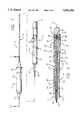
- FIG. 1is a side view of an electrophysiological catheter embodying features of the invention, and illustrating the distal end thereof having an expandable electrode array in its collapsed or unexpanded configuration;
- FIG. 2is a side view of the distal portion of the electrophysiological catheter shown in FIG. 1 illustrating the expandable electrode array in its expanded configuration;
- FIG. 3is a side view of the distal portion of the electrophysiological catheter shown in FIG. 2 illustrating the expanded electrode array with the distal end of the catheter in a deflected configuration;
- FIG. 4is an enlarged partial sectional side view of the distal portion of the catheter shown in FIG. 1;
- FIG. 5is a partial sectional side view of the distal portion of the catheter shown in FIG. 2;
- FIG. 6is a top view of a metallic frame used during fabrication of the expandable array including a plurality of core members of the expandable array;
- FIG. 7is an enlarged broken view of a portion of the core members of the array shown in FIG. 6;
- FIG. 8is a enlarged bottom view of the core members of the array encapsulated in polymeric casings and trimmed from the frame shown in FIG. 6 to form a plurality of array segments;
- FIG. 9is an enlarged, partially broken, partially sectional and rotated side view of the array of FIG. 8;
- FIG. 10is an enlarged cross sectional view of one segment of the array taken along lines 10--10 of FIG. 9, and depicting a sensing electrode mounted thereon in one configuration;
- FIG. 10Ais an enlarged cross sectional view of one segment, similar to that shown in FIG. 10, but illustrating the sensing electrode having a different shape;
- FIG. 11is an enlarged cross sectional view of one segment of the array taken along lines 11--11 of FIG. 9;
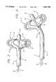
- FIG. 12is an enlarged side view, partially in section, taken along lines 12--12 of FIG. 1 of a manipulation handle secured to the proximal end of the catheter including an array deployment control device in a distal position to collapse the array, and including a deflection control device in its non-operative position (catheter not deflected), and further including a displacement compensation device in accordance with the invention;
- FIG. 13is partially sectional side view of the manipulation handle shown in FIG. 12 including an array deployment control device in its operative position to expand the array, and including a deflection control device in its operative position to deflect the distal end of the catheter;
- FIG. 14is an exploded perspective view, partially in section, of the manipulation handle shown in FIGS. 12 and 13;
- FIG. 15is an enlarged side view of the displacement compensation device shown in FIGS. 12 and 13;
- FIG. 16is an side view, partially in section, of the displacement compensation device shown in FIG. 17;
- FIG. 17is an end view of the displacement compensation device shown in FIGS. 15 and 16.
- the catheter 10includes a manipulation handle 12, an elongated catheter shaft or body member 14, an expandable electrode array 18 located at the distal end 16, a deployment control device 26, and a body member deflection control device 30.
- the expandable electrode array 18includes a plurality of peripheral elongated segments 20 with each segment including an exposed electrode 22 on its exterior, and a generally hemispherical tip electrode 24 at the distal tip of the array 18.
- the body member 14has an inner lumen (not shown) that extends to the distal tip and that has disposed therein a plurality of electrical conductors that are electrically connected to the electrodes 22.
- the deployment control device 26is slidably disposed within the inner lumen of the catheter body member 14 and preferably comprises an electrically conductive deployment mandrel 26 having its distal end not only electrically connected but also mechanically fastened to the tip electrode 24.
- the plurality of distal end segments 20are flexible and resilient and configured in a substantially straight shape so that when bending forces are imparted to the segments, the inherent restoring forces of the material itself tend to straighten the segments to their straight or unbent position when the bending forces have been removed.
- the deployment mandrel 26is used to impart such bending forces counteracting the segments' inherent restoring forces.
- the mandrel 26has axial rigidity so that it can not only be pulled but also pushed to control the deployment of the expandable electrode array 18 at the distal end 16 of the body member 14. Pulling the mandrel 26 deploys the array 18 and pushing the mandrel collapses the array.
- the distal tip of the deployment mandrel 26is attached to the proximal end of the tip electrode 24. Proximal movement of the deployment mandrel 26 will cause the tip electrode to be moved proximally. Because it is mounted on the array segments 20, the segments are forced to move out of the way of the tip electrode. They do so by bending outwardly as shown in FIGS. 2 and 3. The tip electrode can then be pulled into contact with a stop surface 94 at the distal end 16 of the body member 14 of the catheter and into the deployed/expanded position. This creates the planar array of electrodes 22 shown in FIGS. 2 and 3.
- the tip electrode 24is moved distally as are the array segments 20 connected to the electrode 24 and they collapse onto the body member 14 in the straight shape shown in FIG. 1.
- the body member deflection control device 30is also disposed within the catheter body member 14 and has its distal end attached at the distal end 16 of the body member.
- the deflection control devicepreferably comprises a deflection control line 30 having a lubricous coating or jacket (not shown). Pulling the deflection control line 30 will cause a deflection of the distal end 16 of the catheter body member 14.
- the body member 14is fabricated of a flexible, resilient material constructed in substantially a straight shape so that when a bending force is imparted to the body member, an opposing straightening or restoring force originating from the body member itself tends to oppose the bending force. When the bending forces have been removed, the inherent material straightening forces tend to return the body member to its straight shape.
- the deflection control line 30is used to impart such deflection forces to overcome the body member's restoring force and hold the distal end in a deflected position.
- the distal tip of the deflection line 30is affixed by brazing, soldering, or similar means to an anchor band 32 (FIG. 3) mounted in the distal end 16 of the catheter body member 14.
- the control lineis disposed within another lumen formed in the catheter body member 14 so as to be off-set from the central longitudinal axis Of the catheter body member to more easily effect the controlled deflection of the flexible distal end 16.
- the expandable electrode array 18When the expandable electrode array 18 is in its collapsed state, as shown in FIG. 1, sliding movements of the control element 28 operate on the deflection control line 30 to result in selective deflection of the catheter distal end for steering the body member 14.
- the cathetermay be steered so that the body member carrying the electrode array 18 may be positioned at desired locations in a patient's intracardial volume of the heart. Once within the intracardial volume of the heart, the electrode array may be deployed, and the deflection control line 30 controlled to allow the physician to adjust the deflection of the distal end 16 of the catheter 10 for placement of the electrodes against target tissue.
- the electrodes 22 as well as the tip electrode 24may be used both for mapping and ablation.
- the deployment mandrel 26 and the deflection control line 30are preferably formed of a stainless steel suitable for in vivo use, although other materials may be used.
- the deflection line 30in one embodiment was about 0.127 to about 0.254 mm (0.005 to 0.010 inch) in diameter and the deployment mandrel 26 was about 0.254 to about 0.508 mm (0.010 to 0.020 inch) in diameter, and the lengths thereof are appropriate for the catheter in which they are utilized. The above sizes would be adjusted for catheters of different sizes.
- each of the segments 20includes a flexible resilient, electrically conductive metallic core member 34 encapsulated in a polymeric electrically insulative casing 36.
- Each of the respective segmentsis formed with distal, medial, and proximal pre-formed hinge portions, 38, 40 and 42 respectively, such that when the deployment mandrel 26 is retracted, the segments 20 bend at predetermined places and in predetermined orientations at the respective hinge portions to result in the electrodes 22 expanding outwardly to a predetermined configuration.
- a thin sheet of electrically conductive resilient material(not shown), of a thickness on the order of 0.05 mm (0.002 in.) is selected.
- the sheetis composed of a nickel-titanium alloy that provides desired flexibility, resilience, strength, and electrical conductivity.
- stainless steelmay be utilized.
- the sheetis produced using photo-lithography, photo-etching, or other techniques to provide the configuration shown in FIG. 6. As shown, the sheet exhibits a generally square peripheral frame 44 having a generally cruciform blank 46 attached within it, the legs thereof forming the respective core member 34 of each array segment 20, each core member having an inner and an outer end 48 and 50 respectively.
- the respective inner ends 48 of the respective core members 34are attached together by right angle tabs 52 having perforations 53 used later in removing the tabs at designated points.
- the tabsprovide spacing between the inner ends of the core members and provide structural integrity to the blank 46 during the manufacturing process.
- the inner ends of the core membersare spaced a predetermined distance apart.
- the core memberis relatively wide forming a generally rectangular mounting pad 54.
- the mounting padsare joined together by the respective tabs 52.
- Each core memberconvergingly tapers outwardly from the mounting pad to an elongated lead portion 56.
- Relatively thin metallic electrodes 22are affixed to each of the mounting pads 54 of the respective core members 34 by welding, soldering, brazing, or other means, to provide electrical continuity between the electrodes and the core members.
- the electrodes 22comprise highly conductive gold, but may comprise platinum or a platinum alloy in the alternative.
- the bottom side of the blank 46is shown in which the core members 34 have been encapsulated in a polymeric casing 36 utilizing injection molding or over-molding processes known well to those skilled in the art.
- the casing materialis electrically insulative.
- the casings 36are of uniform width along the length of the respective core members.
- the central portion of the blank 46, between the inner ends 48 of the core members 34,is molded and filled with polymeric material to form a generally square central electrode mounting plate 64, the mounting plate formed with a central axial through bore 66.
- the blank 46is trimmed from the frame 44 at the respective outer ends 50 (FIGS. 6 and 7), and the respective tabs 52 are trimmed from the inner ends 48 of the respective core members 34 to form the generally cruciform configuration shown in FIG. 8, the legs thereof defining the segments 20 of the expandable electrode array 18. Because the tabs 52 were broken away, none of the respective core members 34 are in electrical contact with any other so that the core members are electrically isolated from one another.
- the surface of the electrodes 22may then be cleaned or ground to assure that no polymeric material remains over them. In addition, the electrodes 22 may be ground to assure a smooth finish so that no sharp edges exist that may cause trauma to tissues.
- the mounting plate 64is relatively thin with respect to the thickness of the casings 36 of the segments 20.
- the bottom surface at the inner ends 48 of the respective casingsare formed with clearance tapers 68, tapering upwardly and inwardly to the mounting plate to avoid any interference when the segments are bent to the shape shown in FIG. 4.
- the bottom sides of the respective casings 36are formed with a plurality of transverse slots.
- the slotsin one embodiment are molded into the plastic and located at selected distances along the length of the respective segments 20.
- the slotsprovide predetermined bending areas or hinges at which the array will bend when deployed or collapsed, depending on the hinge.
- a first transverse slot 70 defining the distal hinge portion 38is located at the bottom surface of each casing 36, at the inner end 48 thereof, and inside of the inner extremities of the core members 34 and generally at the periphery of the central mounting plate 64. Spaced a predetermined distance outwardly from the first transverse slot are a plurality of adjacent second transverse slots 72 defining the medial hinge portion 40.
- the number of second slots 72 comprising the medial hinge portionis six, however more or fewer slots may be used depending on the arc of curvature desired. Spaced a predetermined distance outwardly from the outward-most slot of the set of second transverse slots is a third transverse slot 74 defining the proximal hinge portion 42.
- each of the respective casings 36 of the segments 20is generally in the form of a circular quadrant having a rounded upper surface 76 and downwardly converging side walls 78.
- the bottom of the casingis formed with a inwardly rounded bottom surface 80 concentric with the rounded upper surface.
- the electrodes 22have a generally rectangular cross-sectional shape with smooth rounded corners at the upper surface.
- the planar upper surface of the electrodeis positioned in a tangential orientation relative to the upper rounded surface 76 of the casing such that the rounded corners of the electrode project from the casing to a minor degree.
- FIG. 10the planar upper surface of the electrode is positioned in a tangential orientation relative to the upper rounded surface 76 of the casing such that the rounded corners of the electrode project from the casing to a minor degree.
- the electrodesmay be formed or ground down to have a rounded contoured upper surface, shaped in conformity with the rounded upper surface 76 of the respective segments.
- the contoured surfaceeliminates the protrusion of any surface beyond the rounded upper surface 76 of the respective segments such that when the array is in its collapsed state, a smoother surface and smaller profile exist.
- a transverse slot 72 of the casing 36traverses the bottom portion of the casing, but does not disturb the integrity of the casing's encapsulation of the core member 34.
- the catheter body member 14includes an inner lumen 82 formed along the central axis thereof extending the length of the body member and the distal extremity of the catheter body member is formed with a tapered countersink 84.
- the distal tip electrode 24is generally of a bullet shape having a hemispherical nose.
- the proximal end of the tip electrode 24includes a projecting mounting stem 86 having an axial bore 88 for receipt of the distal tip of the deployment mandrel 26, the mandrel being affixed therein by crimping, soldering, brazing or other means.
- the stem of the tip electrode 24is passed through the central bore 66 of the mounting plate 64 so that the stem and mandrel project proximally from the bottom side thereof.
- a retaining hub 90is slid over the proximal end of the mandrel and adhesively bonded to the mounting stem sandwiching the mounting plate 66 between the back surface of the tip electrode and the retaining hub 90 to securely affix the tip electrode mounting plate of the expandable array 18.
- the tip electrode 24may be formed with a peripheral slot, held within the frame 44 (FIG. 6), and the polymeric casing molded around it to engage the peripheral slot thereby holding the tip electrode 24 in a fixed position.
- a first tubular sheath 92is provided having a predetermined length and outer diameter, the distal tip thereof defining a stop surface 94.
- the first sheath 92has an inner diameter sized for slidable receipt of the deployment mandrel 26. Because the first sheath 92 and the mandrel 26 are coaxial, the stop surface is in confronting relationship with the retaining hub 90 of the tip electrode 24.
- a pair of small-diameter sealing O-rings 96 having an inner diameter sized for snug receipt of the mandrelare mounted over the mandrel to abut the proximal end of the first sheath and prevent the passage of fluids.
- a flexible elongated second tubular sheath 98is provided proximal to the first sheath 92 and has a similar outer diameter as the first sheath 92. Furthermore, it has a length substantially the length of the catheter body member 14.
- the outer diameter of the second sheathis sized for receipt within the inner lumen 82 of the body member 14 and the inner diameter sized for sliding receipt of the mandrel 26.
- the second sheathis mounted over the mandrel 26 to abut the O rings 96.
- the distal extremity of the first sheathis a predetermined distance from the retaining hub 90 of the tip electrode 24.
- the second sheathis composed of PTFE which provides sufficient lubricity such that the mandrel may slide therein without undue frictional constraint.
- the first sheathis composed of polyimide which provides sufficient rigidity to resist buckling when confronting the retaining hub during deployments of the array.
- the first sheath 92, O-rings 96 and second sheath 98are spaced on the deployment mandrel 26 a predetermined proximal distance from the proximal surface of the mounting plate 66.
- the plastic molding at the proximal and inside portions of the legs 36is stripped off to expose the underlying electrical conductor 34. Electrical leads are attached to the inside surfaces of the legs and the legs are folded closed over a spacing mandrel (not shown). The legs are then all heat melted together, or an appropriate adhesive may be applied to connect them together permanently in the shape provided by the spacing mandrel between the third slots 74 and the outer ends 50 thereof (FIG. 8).
- the segmentsare then heat melted to the distal end of the second sheath 98, the O rings 96, and the proximal end of the first sheath 92.
- an adhesivemay be applied to bond the fused segments to the first and second sheaths 92 and 98 respectively.
- the distal portion of the first sheath 92, distal to the third slot 74,is not bonded to the respective outer ends of the segments.
- the clearance tapers 98 of the respective segmentsprovide clearance for the retaining hub 90 of the tip electrode 24 when the array is in its collapsed state.
- the segments 20clear the first sheath 92 because of their inwardly rounded bottom surfaces 80 (FIG. 10).
- the arrayis hot melted to the distal end of the body member 14 in order to attach it.
- a section of similar materialcan be used as a filler 100 within the joint section.
- the diameter of the arrayis substantially the same diameter as the outer diameter of the catheter body member 14.
- the deployment mandrel 26is free to slide within the first and second sheaths 92 and 98 to expand and collapse the electrode array 18, while the O-rings 96 seal the mandrel so that bodily fluids do not enter the inner lumen 82 of the body member 14.
- the deployment mandrel 26may be pulled proximally relative to the distal end 16 of the body member 14, whereby the distal tip of the mandrel pulls the tip electrode 24 in the proximal direction.
- the peripheral segments 20bend at the distal 38, medial 40, and proximal hinge portions 42.
- the gradual bending at the roedial hinge portion 40 due to a plurality of slots 72prevents the conductive core member 34 from being bent too sharply or at an angle such that the encapsulated core member could break disrupting electrical continuity to the electrode 22.
- the portions of the segments between the distal and roedial hinge portionsresist bending due to the relative large width of the mounting pads 48 and the rigidity of the electrodes 22 mounted thereon.
- the proximal hinge portions 42bend along the third transverse slots 74 relatively easy with limited bending resistance because the polymeric material of the casing is relatively thin.
- the deployment mandrel 26may be pulled proximally far enough such that the retaining hub 90 of the tip electrode 24 contacts the stop surface 94 at the distal end of the first sheath 92.
- the stop surfaceis positioned at a predetermined distance from the retaining hub in the collapsed configuration such that when the retaining hub contacts the stop surface, the forward portions of the respective segments 20 move radially outwardly about the hinge to an extent where the forward portions are disposed in a generally transverse planar orientation relative to one another.
- the electrodes 22are oriented so that they are all forward facing.
- the electrodesWhen in such configuration, the electrodes may more effectively sense electrical signals emanating from the endocardium of the heart and more effectively make contact with the heart tissue to apply ablation energy. Electrical signals are conducted by the respective conductive core members 34 and through the sensor leads (not shown) disposed within the inner lumen 82 of the body member 14 and to a connector (not shown) mounted in the manipulation handle 12.
- the external electrical connector 18(FIG. 1) is connected to signal analysis equipment which provide electrical signal data indications to the physician as well as ablation energy.
- the stop surface 94prevents the deployment mandrel 26 from being retracted within the sheaths 92 and 98 any further which in turn assures that the array 18 is deployed in its predetermined planar orientation while preventing the array from being over-deployed. Deployment of the array at an orientation other than the predetermined orientation may cause irregular electrode sensing characteristics. In addition, over-deployment may cause damage to the internal components of the electrode array.
- the handle 12includes a handle body 110 formed with an elongated hollow cylindrical sleeve 112 having a partition wall 114 near the proximal end thereof and a contoured cap 116 affixed to proximal end of the handle body.
- the contoured cap 116includes an electrical connector 118 (not shown).
- the partition wall 116 of the handle body 110is formed with an axial bore 120 therethrough for receipt of a tubular shaft 122 having an inner lumen 124 and a longitudinal slot 126 extending along the length thereof.
- the shaftnear the proximal end thereof, has a peripheral groove for receiving a spring clip 128, the proximal extremity of the shaft being threaded.
- the proximal end of the shaftis received within the bore 120 of the partition wall 114 so that the threaded extremity projects rearwardly therefrom.
- a nut 130is thereafter threaded onto the proximal end of the shaft to sandwich the partition wall between the spring clip 128 and the nut anchoring the shaft to the handle body concentrically within the hollow sleeve 112 thereof.
- a thread adhesive or a lock washermay be used to hold the nut in place.
- An elongated generally hollow nut element 132is provided having a longitudinal through bore 134.
- the boreis formed with a pair of radially outwardly opposed helical grooves 136 along its longitudinal length.
- the distal end of the nut elementabuts a generally cylindrical bushing 138 formed with a circumferential locking device groove 140 for housing an annular locking device 142.
- the bushingis formed with an axial bore 144 therethrough sized for receipt of the tubular shaft 122 and freely rotates about the shaft.
- a tubular spacer 146is provided having an inner diameter sized for disposition over the tubular shaft 122 and an outer diameter sized for receipt within the bore 134 of the nut element 132.
- the nut element 132, tubular spacer 146 and bushing 138are disposed over the tubular shaft 122 concentrically within the sleeve 112 of the handle body 110 so that the end of the nut element, opposite the bushing, abuts the spring clip 128 at the proximal end of the handle body 110.
- a nut element locking spring clip 148is positioned over the shaft 122 and that abuts the bushing to restrain the nut element from longitudinal movement, while allowing rotational freedom thereof.
- the nut element 132acts as a nut and is rotatable with respect to the handle body 110.
- the nut element 132is provided with a plurality of longitudinally extending guide tracks 150 on the exterior thereof which are adapted to slidably receive respective longitudinal splines 152 disposed on the interior surface of the control element 28, described in more detail below.
- a hollow screw element 154is received within bore 134 of the nut element 132 and includes a pair of opposed projecting helical ridges 155 sized for complementary threaded engagement within the nut element grooves 136. As shown in FIGS. 17 and 18, the screw element includes an inward radial projection 156 or tang. The screw element is disposed over the shaft 122 and the inward projection 156 of the screw element is received within the longitudinal slot 126 of the shaft so that rotation of the screw element is constrained, while longitudinal movement of the screw element relative to the shaft and handle body 110 is provided.
- the deployment mandrel 26is passed proximally through the inner lumen 126 of the shaft 122 and is operatively mounted at its proximal end to the inward projection 156 on the screw element 154.
- the displacement control device 157transmits control movements from the control element 28 to the deployment mandrel 26.
- a distally converging tapered cap 158 having a barbed tubular reinforcing sleeve 160 pressed into proximal end of the capis slidably disposed over the distal end of the tubular shaft 122 and securely affixed thereto.
- the distal end of the capis formed with an axial catheter body member bore 162.
- the proximal end of the catheter body member 14is received in the bore 162 and affixed to the cap by suitable adhesive.
- the control element 28is constructed in two pieces and includes a generally tubular distal sleeve element 164 and a tubular proximal sleeve element 166, the proximal sleeve element having an axial bore 168 therethrough.
- the axial bore 168 of the proximal sleeve elementis sized for slidable receipt of the nut element 132 therein and the outer diameters of the respective sleeve elements are sized for slidable receipt within the hollow sleeve 112 of the handle body 110.
- the distal end of the distal sleeve element 164is formed with a knob 170 configured for convenient grasping by the physician.
- the proximal extremity of the distal sleeve elementis formed with an inner annular groove that defines a retention channel 172.
- the distal end of the proximal sleeve element and the proximal end of the distal sleeve elementare joined together to capture a periphery of a pulley ring 174 within the retention channel 172 forming a substantially continuous cylindrical slide element, wherein the ring is free to rotate within the channel without undue frictional counter force acting on the ring.
- the displacement control device 157that cooperates with the screw element 154 to affect control movements of the deployment mandrel 26 is described in more detail.
- the displacement control device 157includes an elongated metallic tube 176 having an inner lumen, and a pair of biasing members 184 and 188 mounted on the tube.
- the inward projection 156 of the screw element 154is formed with an axial bore 178 therethrough sized for slidable receipt of the metallic tube 176.
- the inner diameter of the lumen of the metallic tubeis sized for receipt of the proximal end of the deployment mandrel 26.
- the proximal end of the mandrel 26is disposed within the inner lumen of the metallic tube and the proximal extremity of the mandrel is affixed to the proximal extremity of the metallic tube, for instance, by crimping, soldering or brazing.
- An electrically conductive jumper wire 180is affixed to the proximal extremity of the metallic tube, such as by soldering or brazing, such that the mandrel is in electrical contact with the jumper wire.
- the jumper wireis then connected to the electrical connector (not shown) at the proximal end of the handle 12.
- a rear stop ring 182is disposed a predetermined distance from the proximal end of the metallic tube and affixed thereto by solder or adhesive.
- a first helical coil spring 184comprises one of the biasing members and is disposed over the metallic tube between the stop ring and the screw element 154.
- An eyelet 186is slidably mounted over the metallic tube between the first spring 184 and the screw element 154 and is free to slide along the metallic tube.
- a second helical coil spring 188of a smaller size than the first spring, comprises a second biasing member and has an inner diameter sized so that it fits over the metallic tube.
- the second spring 188is slidably mounted over the distal end of the metallic tube such that the first and second springs are disposed on opposite sides of the inward projection of the screw element 154.
- a length of shrink tubing 90 in this embodimentis disposed over the distal end of the metallic tube and shrunk about the metallic tube such that the shrink tubing is affixed on the tube and restricts the second spring 188 to remain between it and the screw element 154.
- the slide element 28is rotated relative to the handle body 110. This causes rotation of a nut element 12 which causes linear movement of the screw element 154. Because the inward projection 156 of the screw element 154 is received within the slot 126 of the shaft 122 and therefore constrained from rotation movement relative thereto, the screw element 154 moves only longitudinally along the tubular shaft 122.
- the control element 28has been rotated such that the screw element 154 is disposed in the distal end of the nut element 132.
- the deployment mandrel 26has been pushed distally and has caused the electrode array 18 to collapse as shown in FIG. 1.
- the second spring 188comes into operation. The second spring provides a buffer between the movement of the screw element 154 and the movement of the mandrel.
- the second spring 188will compress thereby storing the excess rotational energy of the control element 28. Therefore the over-rotation of the control element 28 will not place undue mechanical strain on the array elements, which may have included stretching or breakage.
- the second spring 188biases the mandrel in the distal direction. This can be particularly useful in the case where the control device was rotated to its distal position to collapse the array while the distal end of the catheter was deflected. When the catheter becomes straightened, the array may tend to partially deploy as described in the Background section. However, the biasing effect of the second spring automatically moves the mandrel more distally keeping the array collapsed.
- the control element 28is rotated so that it moves proximally relative to the handle body 110 such that the screw element 154 is moved in the proximal direction within the nut element 132, as shown in FIG. 13. Because the deployment mandrel 26 is connected to the metallic tube 176 and the first spring 184 is disposed between the rear stop ring 182 and the proximal end of the inward projection 156 of the screw element 154, longitudinal proximal movement of the screw element compresses the first spring. The compressed first spring 184 induces a spring force to the stop ring 182 to move the metallic tube in a proximal direction resulting in longitudinal movement of the deployment mandrel 26 within the catheter body member 14. As is shown, a gap exists between the second spring 188 and the screw element 154.
- the deployment mandrel 26pulls the tip electrode 24 proximally to flare the respective segments 20 radially outwardly, as shown in FIG. 2, wherein the retaining hub 90 abuts the stop surface 94 of the array.
- the control element 28is further rotated such that the screw element 154 moves proximally a further distance so that the screw element 154 abuts the tubular spacer 146, at the proximal end of the nut element 132.
- This further compression of the first spring 184applies a continuous spring force to the mandrel, such that the retaining hub 90 of the tip electrode 24 abuts the stop surface 94 of the first sheath 92 with a continuous contact force.
- This contact forcemaintains the retaining hub in contact with the stop surface so that the electrode array maintains its predetermined, fully deployed configuration even in the case where the distal end of the catheter is deflected.
- the operation of the deflection control device of the catheter 10is described in detail.
- the deflection of the distal endis controlled by the control element 28 that slides to achieve such deflections.
- the control element 28has been slid to its distal position wherein the control line applies no tensile force to the distal end 16 of the body member and thus the catheter would be disposed in its undetected state as shown in FIG. 1.
- control element 28has been slid to its proximal position. With the control element in this position, the control line has exerted tension on the distal end 16 of the catheter body member 14 deflecting it as shown in FIG. 3.
- deflection control systemSee the co-pending application entitled “Catheter Control System Having A Pulley” by Thornton et al., filed this same day having docket no. 36203.
- the clinicianmay release the control element 28, and it will remain in the position selected due to the inclusion in the handle of a locking device.
- the locking device 142 in this embodimentexerts an outward radial force to impart a continuous locking force against the control element bore 168 sufficient to resist the tensile force of the deflection control line 30.
Landscapes
- Health & Medical Sciences (AREA)
- Life Sciences & Earth Sciences (AREA)
- Engineering & Computer Science (AREA)
- Animal Behavior & Ethology (AREA)
- Veterinary Medicine (AREA)
- Public Health (AREA)
- General Health & Medical Sciences (AREA)
- Biomedical Technology (AREA)
- Heart & Thoracic Surgery (AREA)
- Anesthesiology (AREA)
- Surgery (AREA)
- Pulmonology (AREA)
- Biophysics (AREA)
- Hematology (AREA)
- Mechanical Engineering (AREA)
- Physics & Mathematics (AREA)
- Plasma & Fusion (AREA)
- Nuclear Medicine, Radiotherapy & Molecular Imaging (AREA)
- Otolaryngology (AREA)
- Cardiology (AREA)
- Medical Informatics (AREA)
- Molecular Biology (AREA)
- Surgical Instruments (AREA)
- Media Introduction/Drainage Providing Device (AREA)
Abstract
Description
Claims (22)
Priority Applications (2)
| Application Number | Priority Date | Filing Date | Title |
|---|---|---|---|
| US08/434,003US5681280A (en) | 1995-05-02 | 1995-05-02 | Catheter control system |
| PCT/US1996/006057WO1996034652A1 (en) | 1995-05-02 | 1996-05-01 | Catheter control system |
Applications Claiming Priority (1)
| Application Number | Priority Date | Filing Date | Title |
|---|---|---|---|
| US08/434,003US5681280A (en) | 1995-05-02 | 1995-05-02 | Catheter control system |
Publications (1)
| Publication Number | Publication Date |
|---|---|
| US5681280Atrue US5681280A (en) | 1997-10-28 |
Family
ID=23722419
Family Applications (1)
| Application Number | Title | Priority Date | Filing Date |
|---|---|---|---|
| US08/434,003Expired - LifetimeUS5681280A (en) | 1995-05-02 | 1995-05-02 | Catheter control system |
Country Status (2)
| Country | Link |
|---|---|
| US (1) | US5681280A (en) |
| WO (1) | WO1996034652A1 (en) |
Cited By (222)
| Publication number | Priority date | Publication date | Assignee | Title |
|---|---|---|---|---|
| US5827278A (en)* | 1997-05-20 | 1998-10-27 | Cordis Webster, Inc. | Deflectable tip electrode catheter with nylon stiffener and compression coil |
| US6066125A (en)* | 1997-09-05 | 2000-05-23 | Cordis Webster, Inc. | Omni-directional steerable catheter |
| US6152899A (en)* | 1996-03-05 | 2000-11-28 | Vnus Medical Technologies, Inc. | Expandable catheter having improved electrode design, and method for applying energy |
| US6171277B1 (en) | 1997-12-01 | 2001-01-09 | Cordis Webster, Inc. | Bi-directional control handle for steerable catheter |
| US6183463B1 (en) | 1997-12-01 | 2001-02-06 | Cordis Webster, Inc. | Bidirectional steerable cathether with bidirectional control handle |
| US6197022B1 (en)* | 1996-07-30 | 2001-03-06 | James A. Baker | Medical instruments and techniques for treatment of gastro-esophageal reflux disease |
| US6198974B1 (en) | 1998-08-14 | 2001-03-06 | Cordis Webster, Inc. | Bi-directional steerable catheter |
| US6210407B1 (en) | 1998-12-03 | 2001-04-03 | Cordis Webster, Inc. | Bi-directional electrode catheter |
| US20020077665A1 (en)* | 2000-12-15 | 2002-06-20 | Alsius | Radio frequency patient heating system |
| US6443959B1 (en)* | 1999-02-16 | 2002-09-03 | Instruments Medicaux Gb Inc. | Surgical extractor |
| US6451016B1 (en)* | 1999-07-12 | 2002-09-17 | C. R. Bard, Inc. | Displaceable ablation electrode |
| US6527737B2 (en)* | 2000-01-24 | 2003-03-04 | Tatsuo Kaneshige | Indwelling urethra catheter |
| US6558375B1 (en) | 2000-07-14 | 2003-05-06 | Cardiofocus, Inc. | Cardiac ablation instrument |
| US20030093104A1 (en)* | 1999-10-29 | 2003-05-15 | Bonner Matthew D. | Methods and apparatus for providing intra-pericardial access |
| US6571131B1 (en) | 2000-11-10 | 2003-05-27 | Biosense Webster, Inc. | Deflectable catheter with modifiable handle |
| US6579285B2 (en) | 1994-09-09 | 2003-06-17 | Cardiofocus, Inc. | Photoablation with infrared radiation |
| US6613062B1 (en)* | 1999-10-29 | 2003-09-02 | Medtronic, Inc. | Method and apparatus for providing intra-pericardial access |
| WO2002087409A3 (en)* | 2001-04-02 | 2003-10-02 | Hook Res Foundation | Conformable balloonless catheter |
| US6645160B1 (en)* | 2000-03-17 | 2003-11-11 | Christian M. Heesch | Guide support catheter |
| US6663588B2 (en) | 2000-11-29 | 2003-12-16 | C.R. Bard, Inc. | Active counterforce handle for use in bidirectional deflectable tip instruments |
| US20030236453A1 (en)* | 2002-06-19 | 2003-12-25 | Simon Furnish | Multi-channel catheter tip |
| US6676656B2 (en) | 1994-09-09 | 2004-01-13 | Cardiofocus, Inc. | Surgical ablation with radiant energy |
| EP1417936A1 (en) | 2002-11-11 | 2004-05-12 | Berchtold Holding GmbH | Probe |
| US6740082B2 (en) | 1998-12-29 | 2004-05-25 | John H. Shadduck | Surgical instruments for treating gastro-esophageal reflux |
| US6743225B2 (en) | 2001-03-27 | 2004-06-01 | Uab Research Foundation | Electrophysiologic measure of endpoints for ablation lesions created in fibrillating substrates |
| US20040122499A1 (en)* | 2002-12-23 | 2004-06-24 | Randy Westlund | Coronary vein lead having combination fixation features with lumen restriction and method therefor |
| US20040147913A1 (en)* | 1999-08-25 | 2004-07-29 | Cardiofocus, Inc. | Surgical ablation instruments with irrigation features |
| US6771996B2 (en) | 2001-05-24 | 2004-08-03 | Cardiac Pacemakers, Inc. | Ablation and high-resolution mapping catheter system for pulmonary vein foci elimination |
| US20040167503A1 (en)* | 1999-08-25 | 2004-08-26 | Cardiofocus, Inc. | Malleable surgical ablation instruments |
| US20040181139A1 (en)* | 2001-04-27 | 2004-09-16 | Falwell Gary S. | Method and apparatus for three dimensional mapping of electrical activity in blood vessels and ablation of electrical pathways identified by the three dimension map |
| US20050004504A1 (en)* | 2003-06-24 | 2005-01-06 | Frye Mark R. | Catheter for extracorporeal treatment |
| WO2004087249A3 (en)* | 2003-03-28 | 2005-03-10 | Bard Inc C R | Braided mesh catheter |
| US20050065420A1 (en)* | 2000-05-03 | 2005-03-24 | Collins Russell F. | Apparatus and methods for mapping and ablation in electrophysiology procedures |
| US20050119647A1 (en)* | 2001-05-01 | 2005-06-02 | He Ding S. | Method and apparatus for altering conduction properties in the heart and in adjacent vessels |
| US20050148929A1 (en)* | 2003-11-17 | 2005-07-07 | Bruce Gingles | Catheter with centering wire |
| US20050154370A1 (en)* | 1999-10-29 | 2005-07-14 | Medtronic, Inc. | Methods and systems for providing therapies into the pericardial space |
| US20050237364A1 (en)* | 2004-04-26 | 2005-10-27 | Hirosumi Ito | Printed wiring board and electric device using the same |
| US20060069299A1 (en)* | 1997-09-19 | 2006-03-30 | A-Med Systems, Inc. | Integrated pump and cannula systems and related methods |
| US20060085059A1 (en)* | 2004-03-16 | 2006-04-20 | Michael Ehrlinspiel | Stent having a bridge structure |
| US20060095110A1 (en)* | 2004-10-29 | 2006-05-04 | Scimed Life Systems, Inc. | Implantable medical endoprosthesis delivery systems and related components |
| US20060253025A1 (en)* | 2005-04-21 | 2006-11-09 | Kaufman Jonathan J | Ultrasonic Bone Assessment Apparatus and Method |
| US20070093802A1 (en)* | 2005-10-21 | 2007-04-26 | Danek Christopher J | Energy delivery devices and methods |
| US20070208329A1 (en)* | 2004-12-10 | 2007-09-06 | Jim Ward | Ablative treatment of atrial fibrillation via the coronary sinus |
| US20070255209A1 (en)* | 2006-04-21 | 2007-11-01 | C.R. Bard, Inc. | Feeding device and bolster apparatus and method for making the same |
| US20070276356A1 (en)* | 2004-06-29 | 2007-11-29 | C. R. Bard, Inc. | Methods And Systems For Providing Fluid Communication With A Gastrostomy Tube |
| US7331972B1 (en) | 2002-11-15 | 2008-02-19 | Abbott Cardiovascular Systems Inc. | Heart valve chord cutter |
| US7335213B1 (en) | 2002-11-15 | 2008-02-26 | Abbott Cardiovascular Systems Inc. | Apparatus and methods for heart valve repair |
| US20080058730A1 (en)* | 2006-08-31 | 2008-03-06 | Cook Incorporated | Rotationally actuated fixation mechanism |
| US20080103480A1 (en)* | 2006-10-26 | 2008-05-01 | Cook Critical Care Incorporated | Catheter port configuration |
| US7404824B1 (en) | 2002-11-15 | 2008-07-29 | Advanced Cardiovascular Systems, Inc. | Valve aptation assist device |
| US20080262337A1 (en)* | 2004-05-17 | 2008-10-23 | C.R. Bard, Inc. | Method and Apparatus for Mapping and/or Ablation of Cardiac Tissue |
| US20080275443A1 (en)* | 2004-11-24 | 2008-11-06 | Hakan Oral | Atrial ablation catheter adapted for treatment of septal wall arrhythmogenic foci and method of use |
| US7485143B2 (en) | 2002-11-15 | 2009-02-03 | Abbott Cardiovascular Systems Inc. | Apparatuses and methods for heart valve repair |
| US20090054826A1 (en)* | 2007-08-21 | 2009-02-26 | Cook Critical Care Incorporated | Multi-lumen catheter |
| US20090088631A1 (en)* | 2007-06-28 | 2009-04-02 | W.L. Gore & Associates - Englewood Group (Emd) | Catheter |
| US20090112183A1 (en)* | 2004-05-14 | 2009-04-30 | C. R. Bard, Inc. | Medical devices and methods of use |
| US20090171274A1 (en)* | 2007-12-28 | 2009-07-02 | Doron Harlev | Non contact mapping catheter |
| US7556624B2 (en) | 1997-04-07 | 2009-07-07 | Asthmatx, Inc. | Method of increasing gas exchange of a lung |
| US20090254083A1 (en)* | 2008-03-10 | 2009-10-08 | Hansen Medical, Inc. | Robotic ablation catheter |
| US7632265B2 (en) | 2004-05-28 | 2009-12-15 | St. Jude Medical, Atrial Fibrillation Division, Inc. | Radio frequency ablation servo catheter and method |
| US20100106156A1 (en)* | 1996-03-05 | 2010-04-29 | Tyco Healthcare Group, Lp | Apparatus for treating venous insufficiency |
| US20100145285A1 (en)* | 2008-12-09 | 2010-06-10 | Cook Critical Care, Incorporated | Multi-lumen catheter configuration |
| US20100152731A1 (en)* | 2007-04-04 | 2010-06-17 | Irvine Biomedical, Inc. | Flexible tip catheter with extended fluid lumen |
| US7740638B2 (en) | 2002-10-15 | 2010-06-22 | Abbott Cardiovascular Systems Inc. | Apparatuses and methods for heart valve repair |
| US20100174177A1 (en)* | 2007-07-03 | 2010-07-08 | Kirk Wu | Magnetically guided catheter |
| US20100179567A1 (en)* | 2009-01-09 | 2010-07-15 | Abbott Vascular Inc. | Closure devices, systems, and methods |
| EP2150193A4 (en)* | 2007-05-23 | 2010-08-04 | Irvine Biomedical Inc | ABLATION CATHETER WITH FLEXIBLE END |
| US20100249729A1 (en)* | 1999-10-29 | 2010-09-30 | Medtronic, Inc. | Methods and Systems for Accessing the Pericardial Space |
| US7837679B2 (en) | 2000-10-17 | 2010-11-23 | Asthmatx, Inc. | Control system and process for application of energy to airway walls and other mediums |
| US7853331B2 (en) | 2004-11-05 | 2010-12-14 | Asthmatx, Inc. | Medical device with procedure improvement features |
| US7850685B2 (en) | 2005-06-20 | 2010-12-14 | Medtronic Ablation Frontiers Llc | Ablation catheter |
| US7857808B2 (en) | 2002-10-25 | 2010-12-28 | The Regents Of The University Of Michigan | Ablation catheters |
| US7921855B2 (en) | 1998-01-07 | 2011-04-12 | Asthmatx, Inc. | Method for treating an asthma attack |
| US7931647B2 (en) | 2006-10-20 | 2011-04-26 | Asthmatx, Inc. | Method of delivering energy to a lung airway using markers |
| US7938123B2 (en) | 1997-04-07 | 2011-05-10 | Asthmatx, Inc. | Modification of airways by application of cryo energy |
| US7949407B2 (en) | 2004-11-05 | 2011-05-24 | Asthmatx, Inc. | Energy delivery devices and methods |
| US20110137225A1 (en)* | 2009-12-04 | 2011-06-09 | Cook Critical Care Incorporated | Multi-lumen catheter |
| US7974674B2 (en) | 2004-05-28 | 2011-07-05 | St. Jude Medical, Atrial Fibrillation Division, Inc. | Robotic surgical system and method for surface modeling |
| US7981152B1 (en) | 2004-12-10 | 2011-07-19 | Advanced Cardiovascular Systems, Inc. | Vascular delivery system for accessing and delivering devices into coronary sinus and other vascular sites |
| US7992572B2 (en) | 1998-06-10 | 2011-08-09 | Asthmatx, Inc. | Methods of evaluating individuals having reversible obstructive pulmonary disease |
| US20110196341A1 (en)* | 2010-02-09 | 2011-08-11 | C. R. Bard, Inc. | Deflation indicator for a medical device bolster |
| US7998112B2 (en) | 2003-09-30 | 2011-08-16 | Abbott Cardiovascular Systems Inc. | Deflectable catheter assembly and method of making same |
| US8002729B2 (en) | 2007-08-21 | 2011-08-23 | Cook Medical Technologies Llc | Multi-lumen catheter assembly |
| US20110237955A1 (en)* | 2008-05-30 | 2011-09-29 | Dietz Dennis R | Real Time Ultrasound Catheter Probe |
| US8155910B2 (en) | 2005-05-27 | 2012-04-10 | St. Jude Medical, Atrial Fibrillation Divison, Inc. | Robotically controlled catheter and method of its calibration |
| US8181656B2 (en) | 1998-06-10 | 2012-05-22 | Asthmatx, Inc. | Methods for treating airways |
| US8187324B2 (en) | 2002-11-15 | 2012-05-29 | Advanced Cardiovascular Systems, Inc. | Telescoping apparatus for delivering and adjusting a medical device in a vessel |
| US8236026B2 (en) | 2000-12-07 | 2012-08-07 | Integrated Vascular Systems, Inc. | Closure device and methods for making and using them |
| US8235983B2 (en) | 2007-07-12 | 2012-08-07 | Asthmatx, Inc. | Systems and methods for delivering energy to passageways in a patient |
| US8251070B2 (en) | 2000-03-27 | 2012-08-28 | Asthmatx, Inc. | Methods for treating airways |
| US8257413B2 (en) | 2000-10-17 | 2012-09-04 | Asthmatx, Inc. | Modification of airways by application of energy |
| US8273084B2 (en) | 2004-11-24 | 2012-09-25 | Medtronic Ablation Frontiers Llc | Atrial ablation catheter and method of use |
| US20120271138A1 (en)* | 2011-04-22 | 2012-10-25 | Topera, Inc. | Basket style cardiac mapping catheter having a flexible electrode assembly for detection of cardiac rhythm disorders |
| DE10252325B4 (en)* | 2002-11-11 | 2012-10-25 | Admedes Schuessler Gmbh | Radiofrequency thermal ablation probe and method of making the same |
| US8313497B2 (en) | 2005-07-01 | 2012-11-20 | Abbott Laboratories | Clip applier and methods of use |
| US8323312B2 (en) | 2008-12-22 | 2012-12-04 | Abbott Laboratories | Closure device |
| US20130041314A1 (en)* | 2011-08-11 | 2013-02-14 | Cook Medical Technologies Llc | Steerable Catheters |
| US8398656B2 (en) | 2003-01-30 | 2013-03-19 | Integrated Vascular Systems, Inc. | Clip applier and methods of use |
| US8398676B2 (en) | 2008-10-30 | 2013-03-19 | Abbott Vascular Inc. | Closure device |
| US8443810B2 (en) | 1998-06-10 | 2013-05-21 | Asthmatx, Inc. | Methods of reducing mucus in airways |
| US8469995B2 (en) | 2002-06-04 | 2013-06-25 | Abbott Vascular Inc. | Blood vessel closure clip and delivery device |
| US8483831B1 (en) | 2008-02-15 | 2013-07-09 | Holaira, Inc. | System and method for bronchial dilation |
| US8486063B2 (en) | 2004-10-14 | 2013-07-16 | Medtronic Ablation Frontiers Llc | Ablation catheter |
| US8528565B2 (en) | 2004-05-28 | 2013-09-10 | St. Jude Medical, Atrial Fibrillation Division, Inc. | Robotic surgical system and method for automated therapy delivery |
| US8529587B2 (en) | 2003-01-30 | 2013-09-10 | Integrated Vascular Systems, Inc. | Methods of use of a clip applier |
| US8556930B2 (en) | 2006-06-28 | 2013-10-15 | Abbott Laboratories | Vessel closure device |
| US8579932B2 (en) | 2002-02-21 | 2013-11-12 | Integrated Vascular Systems, Inc. | Sheath apparatus and methods for delivering a closure device |
| US8585836B2 (en) | 2002-12-31 | 2013-11-19 | Integrated Vascular Systems, Inc. | Methods for manufacturing a clip and clip |
| US8590760B2 (en) | 2004-05-25 | 2013-11-26 | Abbott Vascular Inc. | Surgical stapler |
| US8597325B2 (en) | 2000-12-07 | 2013-12-03 | Integrated Vascular Systems, Inc. | Apparatus and methods for providing tactile feedback while delivering a closure device |
| US8603116B2 (en) | 2010-08-04 | 2013-12-10 | Abbott Cardiovascular Systems, Inc. | Closure device with long tines |
| US8617152B2 (en) | 2004-11-15 | 2013-12-31 | Medtronic Ablation Frontiers Llc | Ablation system with feedback |
| US8641704B2 (en) | 2007-05-11 | 2014-02-04 | Medtronic Ablation Frontiers Llc | Ablation therapy system and method for treating continuous atrial fibrillation |
| US8657814B2 (en) | 2005-08-22 | 2014-02-25 | Medtronic Ablation Frontiers Llc | User interface for tissue ablation system |
| US8672953B2 (en) | 2007-12-17 | 2014-03-18 | Abbott Laboratories | Tissue closure system and methods of use |
| US8690910B2 (en) | 2000-12-07 | 2014-04-08 | Integrated Vascular Systems, Inc. | Closure device and methods for making and using them |
| US8694074B2 (en) | 2010-05-11 | 2014-04-08 | Rhythmia Medical, Inc. | Electrode displacement determination |
| US8715244B2 (en) | 2009-07-07 | 2014-05-06 | C. R. Bard, Inc. | Extensible internal bolster for a medical device |
| US8715279B2 (en) | 2007-07-03 | 2014-05-06 | St. Jude Medical, Atrial Fibrillation Division, Inc. | Magnetically guided catheter |
| US8728119B2 (en) | 2001-06-07 | 2014-05-20 | Abbott Vascular Inc. | Surgical staple |
| US8740895B2 (en) | 2009-10-27 | 2014-06-03 | Holaira, Inc. | Delivery devices with coolable energy emitting assemblies |
| US8755864B2 (en) | 2004-05-28 | 2014-06-17 | St. Jude Medical, Atrial Fibrillation Division, Inc. | Robotic surgical system and method for diagnostic data mapping |
| US8758400B2 (en) | 2000-01-05 | 2014-06-24 | Integrated Vascular Systems, Inc. | Closure system and methods of use |
| US8758396B2 (en) | 2000-01-05 | 2014-06-24 | Integrated Vascular Systems, Inc. | Vascular sheath with bioabsorbable puncture site closure apparatus and methods of use |
| US8758399B2 (en) | 2010-08-02 | 2014-06-24 | Abbott Cardiovascular Systems, Inc. | Expandable bioabsorbable plug apparatus and method |
| US8758398B2 (en) | 2006-09-08 | 2014-06-24 | Integrated Vascular Systems, Inc. | Apparatus and method for delivering a closure element |
| US8774913B2 (en) | 2002-04-08 | 2014-07-08 | Medtronic Ardian Luxembourg S.A.R.L. | Methods and apparatus for intravasculary-induced neuromodulation |
| US8784447B2 (en) | 2000-09-08 | 2014-07-22 | Abbott Vascular Inc. | Surgical stapler |
| US8808280B2 (en) | 2008-05-09 | 2014-08-19 | Holaira, Inc. | Systems, assemblies, and methods for treating a bronchial tree |
| US8808310B2 (en) | 2006-04-20 | 2014-08-19 | Integrated Vascular Systems, Inc. | Resettable clip applier and reset tools |
| US8821534B2 (en) | 2010-12-06 | 2014-09-02 | Integrated Vascular Systems, Inc. | Clip applier having improved hemostasis and methods of use |
| US8820602B2 (en) | 2007-12-18 | 2014-09-02 | Abbott Laboratories | Modular clip applier |
| US8834464B2 (en) | 1999-04-05 | 2014-09-16 | Mark T. Stewart | Ablation catheters and associated systems and methods |
| US8834461B2 (en) | 2005-07-11 | 2014-09-16 | Medtronic Ablation Frontiers Llc | Low power tissue ablation system |
| US8852112B2 (en) | 2007-06-28 | 2014-10-07 | W. L. Gore & Associates, Inc. | Catheter with deflectable imaging device and bendable electrical conductor |
| US8858594B2 (en) | 2008-12-22 | 2014-10-14 | Abbott Laboratories | Curved closure device |
| US8858616B2 (en) | 2004-03-16 | 2014-10-14 | Admedes Schuessler Gmbh | Stent having a bridge structure |
| US8864675B2 (en) | 2007-06-28 | 2014-10-21 | W. L. Gore & Associates, Inc. | Catheter |
| US8888773B2 (en) | 2012-05-11 | 2014-11-18 | Medtronic Ardian Luxembourg S.A.R.L. | Multi-electrode catheter assemblies for renal neuromodulation and associated systems and methods |
| US8893947B2 (en) | 2007-12-17 | 2014-11-25 | Abbott Laboratories | Clip applier and methods of use |
| US8905937B2 (en) | 2009-02-26 | 2014-12-09 | Integrated Vascular Systems, Inc. | Methods and apparatus for locating a surface of a body lumen |
| US8911439B2 (en) | 2009-11-11 | 2014-12-16 | Holaira, Inc. | Non-invasive and minimally invasive denervation methods and systems for performing the same |
| US8926656B2 (en) | 2003-01-30 | 2015-01-06 | Integated Vascular Systems, Inc. | Clip applier and methods of use |
| US8926633B2 (en) | 2005-06-24 | 2015-01-06 | Abbott Laboratories | Apparatus and method for delivering a closure element |
| US8934978B2 (en) | 2002-04-08 | 2015-01-13 | Medtronic Ardian Luxembourg S.A.R.L. | Methods and apparatus for renal neuromodulation |
| US8956352B2 (en) | 2010-10-25 | 2015-02-17 | Medtronic Ardian Luxembourg S.A.R.L. | Catheter apparatuses having multi-electrode arrays for renal neuromodulation and associated systems and methods |
| US8956388B2 (en) | 2000-01-05 | 2015-02-17 | Integrated Vascular Systems, Inc. | Integrated vascular device with puncture site closure component and sealant |
| US8974454B2 (en) | 2009-12-31 | 2015-03-10 | St. Jude Medical, Atrial Fibrillation Division, Inc. | Kit for non-invasive electrophysiology procedures and method of its use |
| US9089311B2 (en) | 2009-01-09 | 2015-07-28 | Abbott Vascular Inc. | Vessel closure devices and methods |
| US9089674B2 (en) | 2000-10-06 | 2015-07-28 | Integrated Vascular Systems, Inc. | Apparatus and methods for positioning a vascular sheath |
| US9095321B2 (en) | 2012-11-21 | 2015-08-04 | Medtronic Ardian Luxembourg S.A.R.L. | Cryotherapeutic devices having integral multi-helical balloons and methods of making the same |
| US9149276B2 (en) | 2011-03-21 | 2015-10-06 | Abbott Cardiovascular Systems, Inc. | Clip and deployment apparatus for tissue closure |
| US9149602B2 (en) | 2005-04-22 | 2015-10-06 | Advanced Cardiovascular Systems, Inc. | Dual needle delivery system |
| US9149328B2 (en) | 2009-11-11 | 2015-10-06 | Holaira, Inc. | Systems, apparatuses, and methods for treating tissue and controlling stenosis |
| US9173644B2 (en) | 2009-01-09 | 2015-11-03 | Abbott Vascular Inc. | Closure devices, systems, and methods |
| US9179974B2 (en) | 2013-03-15 | 2015-11-10 | Medtronic Ardian Luxembourg S.A.R.L. | Helical push wire electrode |
| US9248253B2 (en) | 2007-08-21 | 2016-02-02 | Cook Medical Technologies Llc | Winged catheter assembly |
| US9272132B2 (en) | 2012-11-02 | 2016-03-01 | Boston Scientific Scimed, Inc. | Medical device for treating airways and related methods of use |
| US9283374B2 (en) | 2012-11-05 | 2016-03-15 | Boston Scientific Scimed, Inc. | Devices and methods for delivering energy to body lumens |
| US9282965B2 (en) | 2008-05-16 | 2016-03-15 | Abbott Laboratories | Apparatus and methods for engaging tissue |
| US9314230B2 (en) | 2009-01-09 | 2016-04-19 | Abbott Vascular Inc. | Closure device with rapidly eroding anchor |
| US9332976B2 (en) | 2011-11-30 | 2016-05-10 | Abbott Cardiovascular Systems, Inc. | Tissue closure device |
| US9339618B2 (en) | 2003-05-13 | 2016-05-17 | Holaira, Inc. | Method and apparatus for controlling narrowing of at least one airway |
| US9364209B2 (en) | 2012-12-21 | 2016-06-14 | Abbott Cardiovascular Systems, Inc. | Articulating suturing device |
| US9398933B2 (en) | 2012-12-27 | 2016-07-26 | Holaira, Inc. | Methods for improving drug efficacy including a combination of drug administration and nerve modulation |
| US9414824B2 (en) | 2009-01-16 | 2016-08-16 | Abbott Vascular Inc. | Closure devices, systems, and methods |
| US9414820B2 (en) | 2009-01-09 | 2016-08-16 | Abbott Vascular Inc. | Closure devices, systems, and methods |
| CN105962877A (en)* | 2016-06-24 | 2016-09-28 | 武汉佑康科技有限公司 | Displacement compensator for flexible endoscope |
| US9486191B2 (en) | 2009-01-09 | 2016-11-08 | Abbott Vascular, Inc. | Closure devices |
| US9526434B2 (en) | 2006-06-13 | 2016-12-27 | Rhythmia Medical, Inc. | Cardiac mapping with catheter shape information |
| US9579091B2 (en) | 2000-01-05 | 2017-02-28 | Integrated Vascular Systems, Inc. | Closure system and methods of use |
| US9585647B2 (en) | 2009-08-26 | 2017-03-07 | Abbott Laboratories | Medical device for repairing a fistula |
| US9592086B2 (en) | 2012-07-24 | 2017-03-14 | Boston Scientific Scimed, Inc. | Electrodes for tissue treatment |
| US9730602B2 (en) | 2006-06-13 | 2017-08-15 | Boston Scientific Scimed Inc. | Cardiac mapping |
| US9770293B2 (en) | 2012-06-04 | 2017-09-26 | Boston Scientific Scimed, Inc. | Systems and methods for treating tissue of a passageway within a body |
| US9782130B2 (en) | 2004-05-28 | 2017-10-10 | St. Jude Medical, Atrial Fibrillation Division, Inc. | Robotic surgical system |
| US9808178B2 (en) | 2008-10-27 | 2017-11-07 | Boston Scientific Scimed Inc. | Tracking system using field mapping |
| US9814618B2 (en) | 2013-06-06 | 2017-11-14 | Boston Scientific Scimed, Inc. | Devices for delivering energy and related methods of use |
| US9931487B2 (en) | 2015-08-06 | 2018-04-03 | Boston Scientific Scimed, Inc. | Bidirectional steering control apparatus for a catheter |
| US9950138B2 (en) | 2012-07-23 | 2018-04-24 | University Of Utah Research Foundation | Indwelling urinary catheter |
| US10258285B2 (en) | 2004-05-28 | 2019-04-16 | St. Jude Medical, Atrial Fibrillation Division, Inc. | Robotic surgical system and method for automated creation of ablation lesions |
| US10433903B2 (en) | 2007-04-04 | 2019-10-08 | St. Jude Medical, Atrial Fibrillation Division, Inc. | Irrigated catheter |
| US10478247B2 (en) | 2013-08-09 | 2019-11-19 | Boston Scientific Scimed, Inc. | Expandable catheter and related methods of manufacture and use |
| US10492857B2 (en) | 2015-08-06 | 2019-12-03 | Boston Scientific Scimed Inc | Deployment control apparatus for a catheter with a deployable array |
| US10532205B2 (en) | 2017-09-29 | 2020-01-14 | Neuropace, Inc. | Lead fixation accessory, lead stabilization tool, and related procedures |
| US10569050B1 (en) | 2012-02-24 | 2020-02-25 | Christian M. Heesch | Guide catheter support instrument |
| CN111374658A (en)* | 2018-12-29 | 2020-07-07 | 上海微创电生理医疗科技股份有限公司 | Electrophysiology catheter |
| US10736690B2 (en) | 2014-04-24 | 2020-08-11 | Medtronic Ardian Luxembourg S.A.R.L. | Neuromodulation catheters and associated systems and methods |
| US10863945B2 (en) | 2004-05-28 | 2020-12-15 | St. Jude Medical, Atrial Fibrillation Division, Inc. | Robotic surgical system with contact sensing feature |
| CN113274124A (en)* | 2021-06-22 | 2021-08-20 | 上海安钛克医疗科技有限公司 | Electrode assembly, electrophysiology catheter and electrophysiology system |
| US11213678B2 (en) | 2013-09-09 | 2022-01-04 | Medtronic Ardian Luxembourg S.A.R.L. | Method of manufacturing a medical device for neuromodulation |
| US11246658B2 (en) | 2016-10-04 | 2022-02-15 | St. Jude Medical, Cardiology Division, Inc. | Ablation catheter tip |
| US20220071695A1 (en)* | 2020-09-10 | 2022-03-10 | Biosense Webster (Israel) Ltd. | Flex Circuit and Surface Mounted Electrode Catheter |
| US11350986B2 (en) | 2015-03-31 | 2022-06-07 | St. Jude Medical, Cardiology Division, Inc. | High-thermal-sensitivity ablation catheters and catheter tips |
| WO2022143988A1 (en)* | 2020-12-31 | 2022-07-07 | 杭州德诺电生理医疗科技有限公司 | Ablation device and ablation system |
| US20230329784A1 (en)* | 2011-07-29 | 2023-10-19 | Medtronic Ablation Frontiers Llc | Intracardiac tools and methods for delivery of electroporation therapies |
| US11850051B2 (en) | 2019-04-30 | 2023-12-26 | Biosense Webster (Israel) Ltd. | Mapping grid with high density electrode array |
| US11878095B2 (en) | 2018-12-11 | 2024-01-23 | Biosense Webster (Israel) Ltd. | Balloon catheter with high articulation |
| US11918383B2 (en) | 2020-12-21 | 2024-03-05 | Biosense Webster (Israel) Ltd. | Visualizing performance of catheter electrodes |
| US11918341B2 (en) | 2019-12-20 | 2024-03-05 | Biosense Webster (Israel) Ltd. | Selective graphical presentation of electrophysiological parameters |
| US11950841B2 (en) | 2020-09-22 | 2024-04-09 | Biosense Webster (Israel) Ltd. | Basket catheter having insulated ablation electrodes and diagnostic electrodes |
| US11950930B2 (en) | 2019-12-12 | 2024-04-09 | Biosense Webster (Israel) Ltd. | Multi-dimensional acquisition of bipolar signals from a catheter |
| US11950840B2 (en) | 2020-09-22 | 2024-04-09 | Biosense Webster (Israel) Ltd. | Basket catheter having insulated ablation electrodes |
| US11974803B2 (en) | 2020-10-12 | 2024-05-07 | Biosense Webster (Israel) Ltd. | Basket catheter with balloon |
| US11987017B2 (en) | 2020-06-08 | 2024-05-21 | Biosense Webster (Israel) Ltd. | Features to assist in assembly and testing of devices |
| US11992259B2 (en) | 2018-04-11 | 2024-05-28 | Biosense Webster (Israel) Ltd. | Flexible multi-arm catheter with diametrically opposed sensing electrodes |
| US12004804B2 (en) | 2021-09-09 | 2024-06-11 | Biosense Webster (Israel) Ltd. | Basket catheter with mushroom shape distal tip |
| US12011280B2 (en) | 2021-10-04 | 2024-06-18 | Biosense Webster (Israel) Ltd. | Electrophysiological mapping in the presence of injury current |
| US12029545B2 (en) | 2017-05-30 | 2024-07-09 | Biosense Webster (Israel) Ltd. | Catheter splines as location sensors |
| US12042246B2 (en) | 2016-06-09 | 2024-07-23 | Biosense Webster (Israel) Ltd. | Multi-function conducting elements for a catheter |
| US12048479B2 (en) | 2020-09-10 | 2024-07-30 | Biosense Webster (Israel) Ltd. | Surface mounted electrode catheter |
| US12064170B2 (en) | 2021-05-13 | 2024-08-20 | Biosense Webster (Israel) Ltd. | Distal assembly for catheter with lumens running along spines |
| US12082875B2 (en) | 2020-09-24 | 2024-09-10 | Biosense Webster (Israel) Ltd | Balloon catheter having a coil for sensing tissue temperature and position of the balloon |
| US12150700B2 (en) | 2015-08-06 | 2024-11-26 | Medtronic, Inc. | Cardiac pulsed field ablation |
| US12194251B2 (en) | 2018-05-01 | 2025-01-14 | Magellan Biomedical Inc. | System and method for device steering, tracking, and navigation of devices for interventional procedures |
| US12201786B2 (en) | 2020-12-17 | 2025-01-21 | Biosense Webster (Israel) Ltd. | Measurement of distal end dimension of catheters using magnetic fields |
| US12232874B2 (en) | 2020-05-29 | 2025-02-25 | Biosense Webster (Israel) Ltd. | Electrode apparatus for diagnosis of arrhythmias |
| US12295720B2 (en) | 2019-07-18 | 2025-05-13 | Biosense Webster (Israel) Ltd | Visual guidance for positioning a distal end of a medical probe |
| US12329531B2 (en) | 2018-12-28 | 2025-06-17 | Biosense Webster (Israel) Ltd. | Mapping ECG signals using a multipole electrode assembly |
| US12364426B2 (en) | 2021-08-12 | 2025-07-22 | Biosense Webster (Israel) Ltd. | Electro-anatomical mapping and annotation presented in electrophysiological procedures |
| US12419683B2 (en) | 2021-12-22 | 2025-09-23 | Biosense Webster (Israel) Ltd. | Irreversible electroporation with shorted electrodes |
| US12440263B2 (en) | 2022-12-14 | 2025-10-14 | Biosense Webster (Israel) Ltd. | Systems and methods for tripodic spines forming a spherical basket for improved tissue contact and current delivery |
Families Citing this family (14)
| Publication number | Priority date | Publication date | Assignee | Title |
|---|---|---|---|---|
| EP1542587B1 (en) | 2002-08-24 | 2011-04-27 | St. Jude Medical, Atrial Fibrillation Division, Inc. | Method and apparatus for locating the fossa ovalis and performing transseptal puncture |
| EP2032045A2 (en)* | 2006-05-24 | 2009-03-11 | Emcision Limited | Vessel sealing device and methods |
| US8517999B2 (en) | 2007-04-04 | 2013-08-27 | St. Jude Medical, Atrial Fibrillation Division, Inc. | Irrigated catheter with improved fluid flow |
| US10220187B2 (en) | 2010-06-16 | 2019-03-05 | St. Jude Medical, Llc | Ablation catheter having flexible tip with multiple flexible electrode segments |
| US11395694B2 (en) | 2009-05-07 | 2022-07-26 | St. Jude Medical, Llc | Irrigated ablation catheter with multiple segmented ablation electrodes |
| WO2010000020A1 (en)* | 2008-06-30 | 2010-01-07 | Cathrx Ltd | A catheter |
| US8715280B2 (en) | 2010-08-04 | 2014-05-06 | St. Jude Medical, Atrial Fibrillation Division, Inc. | Magnetically guided catheters |
| US9023033B2 (en) | 2010-08-04 | 2015-05-05 | St. Jude Medical, Atrial Fibrillation Division, Inc. | Magnetically guided catheters |
| US8945118B2 (en) | 2010-08-04 | 2015-02-03 | St. Jude Medical, Atrial Fibrillation Division, Inc. | Catheter with flexible tether and introducer for a catheter |
| US8617087B2 (en)* | 2010-12-03 | 2013-12-31 | Biosense Webster, Inc. | Control handle with rotational cam mechanism for contraction/deflection of medical device |
| US8792962B2 (en) | 2010-12-30 | 2014-07-29 | Biosense Webster, Inc. | Catheter with single axial sensors |
| WO2013131046A1 (en)* | 2012-03-01 | 2013-09-06 | Boston Scientific Scimed, Inc. | Off-wall and contact electrode devices and methods for nerve modulation |
| US10849521B2 (en) | 2015-12-23 | 2020-12-01 | Biosense Webster (Israel) Ltd. | Multi-layered catheter shaft construction with embedded single axial sensors, and related methods |
| US12396657B2 (en) | 2021-04-29 | 2025-08-26 | Biosense Webster (Israel) Ltd. | Non-linear single axis navigation sensor with strain relief |
Citations (52)
| Publication number | Priority date | Publication date | Assignee | Title |
|---|---|---|---|---|
| US3452740A (en)* | 1966-05-31 | 1969-07-01 | Us Catheter & Instr Corp | Spring guide manipulator |
| US3470876A (en)* | 1966-09-28 | 1969-10-07 | John Barchilon | Dirigible catheter |
| US3521620A (en)* | 1967-10-30 | 1970-07-28 | William A Cook | Vascular coil spring guide with bendable tip |
| US3552384A (en)* | 1967-07-03 | 1971-01-05 | American Hospital Supply Corp | Controllable tip guide body and catheter |
| US3605725A (en)* | 1968-08-07 | 1971-09-20 | Medi Tech Inc | Controlled motion devices |
| US3610231A (en)* | 1967-07-21 | 1971-10-05 | Olympus Optical Co | Endoscope |
| US4207873A (en)* | 1977-05-16 | 1980-06-17 | American Cystoscope Makers, Inc. | Endoscope deflection control |
| US4483326A (en)* | 1981-04-21 | 1984-11-20 | Kabushiki Kaisha Medos Kenkyusho | Curvature control mechanism in endoscopes |
| US4503842A (en)* | 1981-11-04 | 1985-03-12 | Olympus Optical Co., Ltd. | Endoscope apparatus with electric deflection mechanism |
| US4898577A (en)* | 1988-09-28 | 1990-02-06 | Advanced Cardiovascular Systems, Inc. | Guiding cathether with controllable distal tip |
| US4940062A (en)* | 1988-05-26 | 1990-07-10 | Advanced Cardiovascular Systems, Inc. | Guiding member with deflectable tip |
| US5030204A (en)* | 1988-09-28 | 1991-07-09 | Advanced Cardiovascular Systems, Inc. | Guiding catheter with controllable distal tip |
| US5125896A (en)* | 1990-10-10 | 1992-06-30 | C. R. Bard, Inc. | Steerable electrode catheter |
| US5170787A (en)* | 1990-03-30 | 1992-12-15 | Siemens Aktiengesellschaft | Device for positioning an electrode |
| US5181514A (en)* | 1991-05-21 | 1993-01-26 | Hewlett-Packard Company | Transducer positioning system |
| US5185004A (en)* | 1991-06-03 | 1993-02-09 | Danforth Biomedical, Inc. | Turn-limiting proximal adaptor for steerable catheter systems |
| US5190050A (en)* | 1991-11-08 | 1993-03-02 | Electro-Catheter Corporation | Tip deflectable steerable catheter |
| US5195968A (en)* | 1990-02-02 | 1993-03-23 | Ingemar Lundquist | Catheter steering mechanism |
| US5228441A (en)* | 1991-02-15 | 1993-07-20 | Lundquist Ingemar H | Torquable catheter and method |
| US5242441A (en)* | 1992-02-24 | 1993-09-07 | Boaz Avitall | Deflectable catheter with rotatable tip electrode |
| US5242430A (en)* | 1991-01-17 | 1993-09-07 | Cordis Corporation | Limited turn handle for catheter |
| US5254088A (en)* | 1990-02-02 | 1993-10-19 | Ep Technologies, Inc. | Catheter steering mechanism |
| US5255668A (en)* | 1991-04-08 | 1993-10-26 | Kabushiki Kaisha Machida Seisakusho | Bending device |
| US5255684A (en)* | 1991-10-25 | 1993-10-26 | Interspec, Inc. | Ultrasonic probe assembly |
| US5257451A (en)* | 1991-11-08 | 1993-11-02 | Ep Technologies, Inc. | Method of making durable sleeve for enclosing a bendable electrode tip assembly |
| US5263493A (en)* | 1992-02-24 | 1993-11-23 | Boaz Avitall | Deflectable loop electrode array mapping and ablation catheter for cardiac chambers |
| US5273535A (en)* | 1991-11-08 | 1993-12-28 | Ep Technologies, Inc. | Catheter with electrode tip having asymmetric left and right curve configurations |
| USRE34502E (en)* | 1988-11-18 | 1994-01-11 | Webster, Jr.; Wilton W. | Steerable catheter |
| US5281217A (en)* | 1992-04-13 | 1994-01-25 | Ep Technologies, Inc. | Steerable antenna systems for cardiac ablation that minimize tissue damage and blood coagulation due to conductive heating patterns |
| US5284128A (en)* | 1992-01-24 | 1994-02-08 | Applied Medical Resources Corporation | Surgical manipulator |
| US5318525A (en)* | 1992-04-10 | 1994-06-07 | Medtronic Cardiorhythm | Steerable electrode catheter |
| US5327905A (en)* | 1992-02-14 | 1994-07-12 | Boaz Avitall | Biplanar deflectable catheter for arrhythmogenic tissue ablation |
| US5330466A (en)* | 1992-12-01 | 1994-07-19 | Cardiac Pathways Corporation | Control mechanism and system and method for steering distal extremity of a flexible elongate member |
| US5346504A (en)* | 1992-11-19 | 1994-09-13 | Ethicon, Inc. | Intraluminal manipulator with a head having articulating links |
| US5354297A (en)* | 1992-02-14 | 1994-10-11 | Boaz Avitall | Biplanar deflectable catheter for arrhythmogenic tissue ablation |
| US5358479A (en)* | 1993-12-06 | 1994-10-25 | Electro-Catheter Corporation | Multiform twistable tip deflectable catheter |
| US5363861A (en)* | 1991-11-08 | 1994-11-15 | Ep Technologies, Inc. | Electrode tip assembly with variable resistance to bending |
| US5368564A (en)* | 1992-12-23 | 1994-11-29 | Angeion Corporation | Steerable catheter |
| US5370678A (en)* | 1992-04-13 | 1994-12-06 | Ep Technologies, Inc. | Steerable microwave antenna systems for cardiac ablation that minimize tissue damage and blood coagulation due to conductive heating patterns |
| US5383852A (en)* | 1992-12-04 | 1995-01-24 | C. R. Bard, Inc. | Catheter with independent proximal and distal control |
| US5383923A (en)* | 1990-10-20 | 1995-01-24 | Webster Laboratories, Inc. | Steerable catheter having puller wire with shape memory |
| US5385148A (en)* | 1993-07-30 | 1995-01-31 | The Regents Of The University Of California | Cardiac imaging and ablation catheter |
| US5403297A (en)* | 1993-09-03 | 1995-04-04 | Intelliwire, Inc. | Elongate device having steerable distal extremity and proximal bend and method |
| US5402793A (en)* | 1993-11-19 | 1995-04-04 | Advanced Technology Laboratories, Inc. | Ultrasonic transesophageal probe for the imaging and diagnosis of multiple scan planes |
| US5421832A (en)* | 1989-12-13 | 1995-06-06 | Lefebvre; Jean-Marie | Filter-catheter and method of manufacturing same |
| US5431168A (en)* | 1993-08-23 | 1995-07-11 | Cordis-Webster, Inc. | Steerable open-lumen catheter |
| US5441483A (en)* | 1992-11-16 | 1995-08-15 | Avitall; Boaz | Catheter deflection control |
| US5465716A (en)* | 1993-11-22 | 1995-11-14 | Avitall; Boaz | Catheter control handle |
| US5471982A (en)* | 1992-09-29 | 1995-12-05 | Ep Technologies, Inc. | Cardiac mapping and ablation systems |
| US5476495A (en)* | 1993-03-16 | 1995-12-19 | Ep Technologies, Inc. | Cardiac mapping and ablation systems |
| US5531687A (en)* | 1992-07-06 | 1996-07-02 | Catheter Imaging Systems | Steerable catheter |
| US5549542A (en)* | 1992-11-17 | 1996-08-27 | Life Medical Technologies, Inc. | Deflectable endoscope |
- 1995
- 1995-05-02USUS08/434,003patent/US5681280A/ennot_activeExpired - Lifetime
- 1996
- 1996-05-01WOPCT/US1996/006057patent/WO1996034652A1/enactiveApplication Filing
Patent Citations (54)
| Publication number | Priority date | Publication date | Assignee | Title |
|---|---|---|---|---|
| US3452740A (en)* | 1966-05-31 | 1969-07-01 | Us Catheter & Instr Corp | Spring guide manipulator |
| US3470876A (en)* | 1966-09-28 | 1969-10-07 | John Barchilon | Dirigible catheter |
| US3552384A (en)* | 1967-07-03 | 1971-01-05 | American Hospital Supply Corp | Controllable tip guide body and catheter |
| US3610231A (en)* | 1967-07-21 | 1971-10-05 | Olympus Optical Co | Endoscope |
| US3521620A (en)* | 1967-10-30 | 1970-07-28 | William A Cook | Vascular coil spring guide with bendable tip |
| US3605725A (en)* | 1968-08-07 | 1971-09-20 | Medi Tech Inc | Controlled motion devices |
| US4207873A (en)* | 1977-05-16 | 1980-06-17 | American Cystoscope Makers, Inc. | Endoscope deflection control |
| US4483326A (en)* | 1981-04-21 | 1984-11-20 | Kabushiki Kaisha Medos Kenkyusho | Curvature control mechanism in endoscopes |
| US4503842A (en)* | 1981-11-04 | 1985-03-12 | Olympus Optical Co., Ltd. | Endoscope apparatus with electric deflection mechanism |
| US4940062A (en)* | 1988-05-26 | 1990-07-10 | Advanced Cardiovascular Systems, Inc. | Guiding member with deflectable tip |
| US4898577A (en)* | 1988-09-28 | 1990-02-06 | Advanced Cardiovascular Systems, Inc. | Guiding cathether with controllable distal tip |
| US5030204A (en)* | 1988-09-28 | 1991-07-09 | Advanced Cardiovascular Systems, Inc. | Guiding catheter with controllable distal tip |
| USRE34502E (en)* | 1988-11-18 | 1994-01-11 | Webster, Jr.; Wilton W. | Steerable catheter |
| US5421832A (en)* | 1989-12-13 | 1995-06-06 | Lefebvre; Jean-Marie | Filter-catheter and method of manufacturing same |
| US5395327A (en)* | 1990-02-02 | 1995-03-07 | Ep Technologies, Inc. | Catheter steering mechanism |
| US5531686A (en)* | 1990-02-02 | 1996-07-02 | Ep Technologies, Inc. | Catheter steering mechanism |
| US5195968A (en)* | 1990-02-02 | 1993-03-23 | Ingemar Lundquist | Catheter steering mechanism |
| US5254088A (en)* | 1990-02-02 | 1993-10-19 | Ep Technologies, Inc. | Catheter steering mechanism |
| US5170787A (en)* | 1990-03-30 | 1992-12-15 | Siemens Aktiengesellschaft | Device for positioning an electrode |
| US5125896A (en)* | 1990-10-10 | 1992-06-30 | C. R. Bard, Inc. | Steerable electrode catheter |
| US5383923A (en)* | 1990-10-20 | 1995-01-24 | Webster Laboratories, Inc. | Steerable catheter having puller wire with shape memory |
| US5242430A (en)* | 1991-01-17 | 1993-09-07 | Cordis Corporation | Limited turn handle for catheter |
| US5228441A (en)* | 1991-02-15 | 1993-07-20 | Lundquist Ingemar H | Torquable catheter and method |
| US5255668A (en)* | 1991-04-08 | 1993-10-26 | Kabushiki Kaisha Machida Seisakusho | Bending device |
| US5181514A (en)* | 1991-05-21 | 1993-01-26 | Hewlett-Packard Company | Transducer positioning system |
| US5185004A (en)* | 1991-06-03 | 1993-02-09 | Danforth Biomedical, Inc. | Turn-limiting proximal adaptor for steerable catheter systems |
| US5255684A (en)* | 1991-10-25 | 1993-10-26 | Interspec, Inc. | Ultrasonic probe assembly |
| US5273535A (en)* | 1991-11-08 | 1993-12-28 | Ep Technologies, Inc. | Catheter with electrode tip having asymmetric left and right curve configurations |
| US5190050A (en)* | 1991-11-08 | 1993-03-02 | Electro-Catheter Corporation | Tip deflectable steerable catheter |
| US5257451A (en)* | 1991-11-08 | 1993-11-02 | Ep Technologies, Inc. | Method of making durable sleeve for enclosing a bendable electrode tip assembly |
| US5363861A (en)* | 1991-11-08 | 1994-11-15 | Ep Technologies, Inc. | Electrode tip assembly with variable resistance to bending |
| US5284128A (en)* | 1992-01-24 | 1994-02-08 | Applied Medical Resources Corporation | Surgical manipulator |
| US5354297A (en)* | 1992-02-14 | 1994-10-11 | Boaz Avitall | Biplanar deflectable catheter for arrhythmogenic tissue ablation |
| US5327905A (en)* | 1992-02-14 | 1994-07-12 | Boaz Avitall | Biplanar deflectable catheter for arrhythmogenic tissue ablation |
| US5263493A (en)* | 1992-02-24 | 1993-11-23 | Boaz Avitall | Deflectable loop electrode array mapping and ablation catheter for cardiac chambers |
| US5242441A (en)* | 1992-02-24 | 1993-09-07 | Boaz Avitall | Deflectable catheter with rotatable tip electrode |
| US5318525A (en)* | 1992-04-10 | 1994-06-07 | Medtronic Cardiorhythm | Steerable electrode catheter |
| US5370678A (en)* | 1992-04-13 | 1994-12-06 | Ep Technologies, Inc. | Steerable microwave antenna systems for cardiac ablation that minimize tissue damage and blood coagulation due to conductive heating patterns |
| US5281217A (en)* | 1992-04-13 | 1994-01-25 | Ep Technologies, Inc. | Steerable antenna systems for cardiac ablation that minimize tissue damage and blood coagulation due to conductive heating patterns |
| US5531687A (en)* | 1992-07-06 | 1996-07-02 | Catheter Imaging Systems | Steerable catheter |
| US5471982A (en)* | 1992-09-29 | 1995-12-05 | Ep Technologies, Inc. | Cardiac mapping and ablation systems |
| US5441483A (en)* | 1992-11-16 | 1995-08-15 | Avitall; Boaz | Catheter deflection control |
| US5549542A (en)* | 1992-11-17 | 1996-08-27 | Life Medical Technologies, Inc. | Deflectable endoscope |
| US5346504A (en)* | 1992-11-19 | 1994-09-13 | Ethicon, Inc. | Intraluminal manipulator with a head having articulating links |
| US5330466A (en)* | 1992-12-01 | 1994-07-19 | Cardiac Pathways Corporation | Control mechanism and system and method for steering distal extremity of a flexible elongate member |
| US5383852A (en)* | 1992-12-04 | 1995-01-24 | C. R. Bard, Inc. | Catheter with independent proximal and distal control |
| US5368564A (en)* | 1992-12-23 | 1994-11-29 | Angeion Corporation | Steerable catheter |
| US5476495A (en)* | 1993-03-16 | 1995-12-19 | Ep Technologies, Inc. | Cardiac mapping and ablation systems |
| US5385148A (en)* | 1993-07-30 | 1995-01-31 | The Regents Of The University Of California | Cardiac imaging and ablation catheter |
| US5431168A (en)* | 1993-08-23 | 1995-07-11 | Cordis-Webster, Inc. | Steerable open-lumen catheter |
| US5403297A (en)* | 1993-09-03 | 1995-04-04 | Intelliwire, Inc. | Elongate device having steerable distal extremity and proximal bend and method |
| US5402793A (en)* | 1993-11-19 | 1995-04-04 | Advanced Technology Laboratories, Inc. | Ultrasonic transesophageal probe for the imaging and diagnosis of multiple scan planes |
| US5465716A (en)* | 1993-11-22 | 1995-11-14 | Avitall; Boaz | Catheter control handle |
| US5358479A (en)* | 1993-12-06 | 1994-10-25 | Electro-Catheter Corporation | Multiform twistable tip deflectable catheter |
Cited By (440)
| Publication number | Priority date | Publication date | Assignee | Title |
|---|---|---|---|---|
| US6579285B2 (en) | 1994-09-09 | 2003-06-17 | Cardiofocus, Inc. | Photoablation with infrared radiation |
| US6676656B2 (en) | 1994-09-09 | 2004-01-13 | Cardiofocus, Inc. | Surgical ablation with radiant energy |
| US20100106156A1 (en)* | 1996-03-05 | 2010-04-29 | Tyco Healthcare Group, Lp | Apparatus for treating venous insufficiency |
| US6638273B1 (en) | 1996-03-05 | 2003-10-28 | Vnus Medical Technologies, Inc. | Expandable catheter having improved electrode design, and method for applying energy |
| US6152899A (en)* | 1996-03-05 | 2000-11-28 | Vnus Medical Technologies, Inc. | Expandable catheter having improved electrode design, and method for applying energy |
| US7967782B2 (en)* | 1996-03-05 | 2011-06-28 | Tyco Healthcare Group Lp | Apparatus for treating venous insufficiency |
| US6197022B1 (en)* | 1996-07-30 | 2001-03-06 | James A. Baker | Medical instruments and techniques for treatment of gastro-esophageal reflux disease |
| US7167758B2 (en) | 1996-08-30 | 2007-01-23 | Baker James A | Medical instruments and techniques for treatment of gastro-esophageal reflux disease |
| US6535768B1 (en) | 1996-08-30 | 2003-03-18 | James A. Baker | Medical instruments and techniques for treatment of gastro-esophageal reflux disease |
| US20030130710A1 (en)* | 1996-08-30 | 2003-07-10 | Baker James A. | Medical instruments and techniques for treatment of gastro-esophageal reflux disease |
| US11033317B2 (en) | 1997-04-07 | 2021-06-15 | Boston Scientific Scimed, Inc. | Methods for treating a lung |
| US9956023B2 (en) | 1997-04-07 | 2018-05-01 | Boston Scientific Scimed, Inc. | System for treating a lung |
| US8944071B2 (en) | 1997-04-07 | 2015-02-03 | Asthmatx, Inc. | Method for treating an asthma attack |
| US7556624B2 (en) | 1997-04-07 | 2009-07-07 | Asthmatx, Inc. | Method of increasing gas exchange of a lung |
| US8267094B2 (en) | 1997-04-07 | 2012-09-18 | Asthmatx, Inc. | Modification of airways by application of ultrasound energy |
| US10058370B2 (en) | 1997-04-07 | 2018-08-28 | Boston Scientific Scimed, Inc. | Method for treating a lung |
| US8161978B2 (en) | 1997-04-07 | 2012-04-24 | Asthmatx, Inc. | Methods for treating asthma by damaging nerve tissue |
| US7938123B2 (en) | 1997-04-07 | 2011-05-10 | Asthmatx, Inc. | Modification of airways by application of cryo energy |
| US8640711B2 (en) | 1997-04-07 | 2014-02-04 | Asthmatx, Inc. | Method for treating an asthma attack |
| US9027564B2 (en) | 1997-04-07 | 2015-05-12 | Asthmatx, Inc. | Method for treating a lung |
| US5827278A (en)* | 1997-05-20 | 1998-10-27 | Cordis Webster, Inc. | Deflectable tip electrode catheter with nylon stiffener and compression coil |
| US8095222B2 (en) | 1997-08-28 | 2012-01-10 | Baker James A | Medical instruments and techniques for treatment of gastro-esophageal reflux disease |
| US20070118109A1 (en)* | 1997-08-28 | 2007-05-24 | Baker James A | Medical instruments and techniques for treatment of gastro-esophageal reflux disease |
| US6066125A (en)* | 1997-09-05 | 2000-05-23 | Cordis Webster, Inc. | Omni-directional steerable catheter |
| US6500167B1 (en) | 1997-09-05 | 2002-12-31 | Biosense Webster, Inc. | Omni-directional steerable catheter |
| US6123699A (en)* | 1997-09-05 | 2000-09-26 | Cordis Webster, Inc. | Omni-directional steerable catheter |
| US20060069299A1 (en)* | 1997-09-19 | 2006-03-30 | A-Med Systems, Inc. | Integrated pump and cannula systems and related methods |
| US6171277B1 (en) | 1997-12-01 | 2001-01-09 | Cordis Webster, Inc. | Bi-directional control handle for steerable catheter |
| US6183463B1 (en) | 1997-12-01 | 2001-02-06 | Cordis Webster, Inc. | Bidirectional steerable cathether with bidirectional control handle |
| US7921855B2 (en) | 1998-01-07 | 2011-04-12 | Asthmatx, Inc. | Method for treating an asthma attack |
| US8584681B2 (en) | 1998-01-07 | 2013-11-19 | Asthmatx, Inc. | Method for treating an asthma attack |
| US9789331B2 (en) | 1998-01-07 | 2017-10-17 | Boston Scientific Scimed, Inc. | Methods of treating a lung |
| US7507239B2 (en) | 1998-05-20 | 2009-03-24 | Shadduck John H | Surgical instruments and techniques for treating gastro-esophageal reflux disease |
| US20060149224A1 (en)* | 1998-05-20 | 2006-07-06 | Shadduck John H | Surgical instruments and techniques for treating gastro-esophageal reflux disease |
| US20100042091A1 (en)* | 1998-05-20 | 2010-02-18 | Mederi Therapeutics, Inc. | Surgical instruments and techniques for treating gastro-esophageal reflux disease |
| US8556952B2 (en) | 1998-05-20 | 2013-10-15 | Mederi Therapeutics Inc. | Surgical instruments and techniques for treating gastro-esophageal reflux disease |
| US7008419B2 (en) | 1998-05-20 | 2006-03-07 | Shadduck John H | Surgical instruments and techniques for treating gastro-esophageal reflux disease |
| US20070142831A1 (en)* | 1998-05-20 | 2007-06-21 | Shadduck John H | Surgical Instruments And Techniques For Treating Gastro-Esophageal Reflux Disease |
| US20040254622A1 (en)* | 1998-05-20 | 2004-12-16 | Shadduck John H. | Surgical instruments and techniques for treating gastro-esophageal reflux disease |
| US7992572B2 (en) | 1998-06-10 | 2011-08-09 | Asthmatx, Inc. | Methods of evaluating individuals having reversible obstructive pulmonary disease |
| US8443810B2 (en) | 1998-06-10 | 2013-05-21 | Asthmatx, Inc. | Methods of reducing mucus in airways |
| US8181656B2 (en) | 1998-06-10 | 2012-05-22 | Asthmatx, Inc. | Methods for treating airways |
| US8733367B2 (en) | 1998-06-10 | 2014-05-27 | Asthmatx, Inc. | Methods of treating inflammation in airways |
| US8534291B2 (en) | 1998-06-10 | 2013-09-17 | Asthmatx, Inc. | Methods of treating inflammation in airways |
| US8464723B2 (en) | 1998-06-10 | 2013-06-18 | Asthmatx, Inc. | Methods of evaluating individuals having reversible obstructive pulmonary disease |
| US6198974B1 (en) | 1998-08-14 | 2001-03-06 | Cordis Webster, Inc. | Bi-directional steerable catheter |
| US6210407B1 (en) | 1998-12-03 | 2001-04-03 | Cordis Webster, Inc. | Bi-directional electrode catheter |
| US6740082B2 (en) | 1998-12-29 | 2004-05-25 | John H. Shadduck | Surgical instruments for treating gastro-esophageal reflux |
| US6443959B1 (en)* | 1999-02-16 | 2002-09-03 | Instruments Medicaux Gb Inc. | Surgical extractor |
| US8834464B2 (en) | 1999-04-05 | 2014-09-16 | Mark T. Stewart | Ablation catheters and associated systems and methods |
| US9554848B2 (en) | 1999-04-05 | 2017-01-31 | Medtronic, Inc. | Ablation catheters and associated systems and methods |
| US6451016B1 (en)* | 1999-07-12 | 2002-09-17 | C. R. Bard, Inc. | Displaceable ablation electrode |
| US20040147913A1 (en)* | 1999-08-25 | 2004-07-29 | Cardiofocus, Inc. | Surgical ablation instruments with irrigation features |
| US20040167503A1 (en)* | 1999-08-25 | 2004-08-26 | Cardiofocus, Inc. | Malleable surgical ablation instruments |
| US6613062B1 (en)* | 1999-10-29 | 2003-09-02 | Medtronic, Inc. | Method and apparatus for providing intra-pericardial access |
| US20050154370A1 (en)* | 1999-10-29 | 2005-07-14 | Medtronic, Inc. | Methods and systems for providing therapies into the pericardial space |
| US8852173B2 (en) | 1999-10-29 | 2014-10-07 | Medtronic, Inc. | Methods and systems for providing therapies into the pericardial space |
| US20040087938A1 (en)* | 1999-10-29 | 2004-05-06 | Medtronic, Inc. | Method and apparatus for providing intra-pericardial access |
| US7207988B2 (en) | 1999-10-29 | 2007-04-24 | Medtronic Inc. | Method and apparatus for providing intra-pericardial access |
| US8475468B2 (en) | 1999-10-29 | 2013-07-02 | Medtronic, Inc. | Method and apparatus for providing intra-pericardial access |
| US20040024435A1 (en)* | 1999-10-29 | 2004-02-05 | Leckrone Michael E. | Method and apparatus for providing intra-pericardial access |
| US20030093104A1 (en)* | 1999-10-29 | 2003-05-15 | Bonner Matthew D. | Methods and apparatus for providing intra-pericardial access |
| US8000807B2 (en) | 1999-10-29 | 2011-08-16 | Medtronic, Inc. | Methods and systems for accessing the pericardial space |
| US20100249729A1 (en)* | 1999-10-29 | 2010-09-30 | Medtronic, Inc. | Methods and Systems for Accessing the Pericardial Space |
| US10111664B2 (en) | 2000-01-05 | 2018-10-30 | Integrated Vascular Systems, Inc. | Closure system and methods of use |
| US9579091B2 (en) | 2000-01-05 | 2017-02-28 | Integrated Vascular Systems, Inc. | Closure system and methods of use |
| US8758400B2 (en) | 2000-01-05 | 2014-06-24 | Integrated Vascular Systems, Inc. | Closure system and methods of use |
| US8758396B2 (en) | 2000-01-05 | 2014-06-24 | Integrated Vascular Systems, Inc. | Vascular sheath with bioabsorbable puncture site closure apparatus and methods of use |
| US8956388B2 (en) | 2000-01-05 | 2015-02-17 | Integrated Vascular Systems, Inc. | Integrated vascular device with puncture site closure component and sealant |
| US9050087B2 (en) | 2000-01-05 | 2015-06-09 | Integrated Vascular Systems, Inc. | Integrated vascular device with puncture site closure component and sealant and methods of use |
| US6527737B2 (en)* | 2000-01-24 | 2003-03-04 | Tatsuo Kaneshige | Indwelling urethra catheter |
| US6645160B1 (en)* | 2000-03-17 | 2003-11-11 | Christian M. Heesch | Guide support catheter |
| US8459268B2 (en) | 2000-03-27 | 2013-06-11 | Asthmatx, Inc. | Methods for treating airways |
| US9358024B2 (en) | 2000-03-27 | 2016-06-07 | Asthmatx, Inc. | Methods for treating airways |
| US10561458B2 (en) | 2000-03-27 | 2020-02-18 | Boston Scientific Scimed, Inc. | Methods for treating airways |
| US8251070B2 (en) | 2000-03-27 | 2012-08-28 | Asthmatx, Inc. | Methods for treating airways |
| US10278766B2 (en) | 2000-03-27 | 2019-05-07 | Boston Scientific Scimed, Inc. | Methods for treating airways |
| US8157796B2 (en) | 2000-05-03 | 2012-04-17 | C.R. Bard, Inc. | Apparatus and methods for mapping and ablation in electrophysiology procedures |
| US9028486B2 (en) | 2000-05-03 | 2015-05-12 | Boston Scientific Scimed Inc. | Methods of using a catheter having a braided conductive member |
| US20050065420A1 (en)* | 2000-05-03 | 2005-03-24 | Collins Russell F. | Apparatus and methods for mapping and ablation in electrophysiology procedures |
| US20080058800A1 (en)* | 2000-05-03 | 2008-03-06 | C.R. Bard, Inc. | Apparatus and methods for mapping and ablation in electrophysiology procedures |
| US7306594B2 (en) | 2000-05-03 | 2007-12-11 | C.R. Bard, Inc. | Apparatus and methods for mapping and ablation in electrophysiology procedures |
| US6558375B1 (en) | 2000-07-14 | 2003-05-06 | Cardiofocus, Inc. | Cardiac ablation instrument |
| US9060769B2 (en) | 2000-09-08 | 2015-06-23 | Abbott Vascular Inc. | Surgical stapler |
| US9402625B2 (en) | 2000-09-08 | 2016-08-02 | Abbott Vascular Inc. | Surgical stapler |
| US8784447B2 (en) | 2000-09-08 | 2014-07-22 | Abbott Vascular Inc. | Surgical stapler |
| US9089674B2 (en) | 2000-10-06 | 2015-07-28 | Integrated Vascular Systems, Inc. | Apparatus and methods for positioning a vascular sheath |
| US7837679B2 (en) | 2000-10-17 | 2010-11-23 | Asthmatx, Inc. | Control system and process for application of energy to airway walls and other mediums |
| US8465486B2 (en) | 2000-10-17 | 2013-06-18 | Asthmatx, Inc. | Modification of airways by application of energy |
| US9931163B2 (en) | 2000-10-17 | 2018-04-03 | Boston Scientific Scimed, Inc. | Energy delivery devices |
| US8257413B2 (en) | 2000-10-17 | 2012-09-04 | Asthmatx, Inc. | Modification of airways by application of energy |
| US9033976B2 (en) | 2000-10-17 | 2015-05-19 | Asthmatx, Inc. | Modification of airways by application of energy |
| US7854734B2 (en) | 2000-10-17 | 2010-12-21 | Asthmatx, Inc. | Control system and process for application of energy to airway walls and other mediums |
| US8888769B2 (en) | 2000-10-17 | 2014-11-18 | Asthmatx, Inc. | Control system and process for application of energy to airway walls and other mediums |
| US6571131B1 (en) | 2000-11-10 | 2003-05-27 | Biosense Webster, Inc. | Deflectable catheter with modifiable handle |
| US7524301B2 (en) | 2000-11-29 | 2009-04-28 | C.R. Bard, Inc. | Active counterforce handle for use in bidirectional deflectable tip instruments |
| US6663588B2 (en) | 2000-11-29 | 2003-12-16 | C.R. Bard, Inc. | Active counterforce handle for use in bidirectional deflectable tip instruments |
| US20040127847A1 (en)* | 2000-11-29 | 2004-07-01 | Dubois Tom | Active counterforce handle for use in bidirectional deflectable tip instruments |
| US8236026B2 (en) | 2000-12-07 | 2012-08-07 | Integrated Vascular Systems, Inc. | Closure device and methods for making and using them |
| US8486092B2 (en) | 2000-12-07 | 2013-07-16 | Integrated Vascular Systems, Inc. | Closure device and methods for making and using them |
| US8603136B2 (en) | 2000-12-07 | 2013-12-10 | Integrated Vascular Systems, Inc. | Apparatus and methods for providing tactile feedback while delivering a closure device |
| US9320522B2 (en) | 2000-12-07 | 2016-04-26 | Integrated Vascular Systems, Inc. | Closure device and methods for making and using them |
| US9554786B2 (en) | 2000-12-07 | 2017-01-31 | Integrated Vascular Systems, Inc. | Closure device and methods for making and using them |
| US8597325B2 (en) | 2000-12-07 | 2013-12-03 | Integrated Vascular Systems, Inc. | Apparatus and methods for providing tactile feedback while delivering a closure device |
| US10245013B2 (en) | 2000-12-07 | 2019-04-02 | Integrated Vascular Systems, Inc. | Closure device and methods for making and using them |
| US8486108B2 (en) | 2000-12-07 | 2013-07-16 | Integrated Vascular Systems, Inc. | Closure device and methods for making and using them |
| US9585646B2 (en) | 2000-12-07 | 2017-03-07 | Integrated Vascular Systems, Inc. | Closure device and methods for making and using them |
| US8690910B2 (en) | 2000-12-07 | 2014-04-08 | Integrated Vascular Systems, Inc. | Closure device and methods for making and using them |
| US6699268B2 (en)* | 2000-12-15 | 2004-03-02 | Alsius Corporation | Radio frequency patient heating system |
| US20020077665A1 (en)* | 2000-12-15 | 2002-06-20 | Alsius | Radio frequency patient heating system |
| US6743225B2 (en) | 2001-03-27 | 2004-06-01 | Uab Research Foundation | Electrophysiologic measure of endpoints for ablation lesions created in fibrillating substrates |
| WO2002087409A3 (en)* | 2001-04-02 | 2003-10-02 | Hook Res Foundation | Conformable balloonless catheter |
| US20040181139A1 (en)* | 2001-04-27 | 2004-09-16 | Falwell Gary S. | Method and apparatus for three dimensional mapping of electrical activity in blood vessels and ablation of electrical pathways identified by the three dimension map |
| US7255695B2 (en) | 2001-04-27 | 2007-08-14 | C.R. Bard, Inc. | Systems and methods for three-dimensional mapping of electrical activity |
| US7727229B2 (en) | 2001-05-01 | 2010-06-01 | C.R. Bard, Inc. | Method and apparatus for altering conduction properties in the heart and in adjacent vessels |
| US20050119647A1 (en)* | 2001-05-01 | 2005-06-02 | He Ding S. | Method and apparatus for altering conduction properties in the heart and in adjacent vessels |
| US8951247B2 (en) | 2001-05-01 | 2015-02-10 | Boston Scientific Scimed, Inc. | Methods and apparatus for forming cardiac lesions and assessing lesion quality |
| US6771996B2 (en) | 2001-05-24 | 2004-08-03 | Cardiac Pacemakers, Inc. | Ablation and high-resolution mapping catheter system for pulmonary vein foci elimination |
| US8728119B2 (en) | 2001-06-07 | 2014-05-20 | Abbott Vascular Inc. | Surgical staple |
| US10016592B2 (en) | 2001-10-17 | 2018-07-10 | Boston Scientific Scimed, Inc. | Control system and process for application of energy to airway walls and other mediums |
| US8579932B2 (en) | 2002-02-21 | 2013-11-12 | Integrated Vascular Systems, Inc. | Sheath apparatus and methods for delivering a closure device |
| US10201340B2 (en) | 2002-02-21 | 2019-02-12 | Integrated Vascular Systems, Inc. | Sheath apparatus and methods for delivering a closure device |
| US9498196B2 (en) | 2002-02-21 | 2016-11-22 | Integrated Vascular Systems, Inc. | Sheath apparatus and methods for delivering a closure device |
| US9289255B2 (en) | 2002-04-08 | 2016-03-22 | Medtronic Ardian Luxembourg S.A.R.L. | Methods and apparatus for renal neuromodulation |
| US9675413B2 (en) | 2002-04-08 | 2017-06-13 | Medtronic Ardian Luxembourg S.A.R.L. | Methods and apparatus for renal neuromodulation |
| US8934978B2 (en) | 2002-04-08 | 2015-01-13 | Medtronic Ardian Luxembourg S.A.R.L. | Methods and apparatus for renal neuromodulation |
| US8774913B2 (en) | 2002-04-08 | 2014-07-08 | Medtronic Ardian Luxembourg S.A.R.L. | Methods and apparatus for intravasculary-induced neuromodulation |
| US9295469B2 (en) | 2002-06-04 | 2016-03-29 | Abbott Vascular Inc. | Blood vessel closure clip and delivery device |
| US8469995B2 (en) | 2002-06-04 | 2013-06-25 | Abbott Vascular Inc. | Blood vessel closure clip and delivery device |
| US9980728B2 (en) | 2002-06-04 | 2018-05-29 | Abbott Vascular Inc | Blood vessel closure clip and delivery device |
| US8280495B2 (en) | 2002-06-19 | 2012-10-02 | Infraredx, Inc. | Multi-channel catheter tip |
| US20030236453A1 (en)* | 2002-06-19 | 2003-12-25 | Simon Furnish | Multi-channel catheter tip |
| US20100217131A1 (en)* | 2002-06-19 | 2010-08-26 | Infraredx, Inc. | Multi-channel catheter tip |
| US7672713B2 (en)* | 2002-06-19 | 2010-03-02 | Infraredx, Inc. | Multi-channel catheter tip |
| US7740638B2 (en) | 2002-10-15 | 2010-06-22 | Abbott Cardiovascular Systems Inc. | Apparatuses and methods for heart valve repair |
| US8133272B2 (en) | 2002-10-15 | 2012-03-13 | Advanced Cardiovascular Systems, Inc. | Apparatuses and methods for heart valve repair |
| US7857808B2 (en) | 2002-10-25 | 2010-12-28 | The Regents Of The University Of Michigan | Ablation catheters |
| US7993333B2 (en) | 2002-10-25 | 2011-08-09 | The Regents Of The University Of Michigan | Ablation catheters |
| US20060129143A1 (en)* | 2002-11-11 | 2006-06-15 | Erik Flaxmeier | Metal electrode |
| DE10252325B4 (en)* | 2002-11-11 | 2012-10-25 | Admedes Schuessler Gmbh | Radiofrequency thermal ablation probe and method of making the same |
| US7988662B2 (en) | 2002-11-11 | 2011-08-02 | Admedes Schuessler Gmbh | Metal electrode |
| EP1417936B1 (en)* | 2002-11-11 | 2011-05-04 | Admedes Schuessler GmbH | Probe with a metal electrode and method of manufacturing such an electrode |
| WO2004043279A3 (en)* | 2002-11-11 | 2004-08-05 | Admedes Schuessler Gmbh | Metal electrode |
| EP1417936A1 (en) | 2002-11-11 | 2004-05-12 | Berchtold Holding GmbH | Probe |
| US7942928B2 (en) | 2002-11-15 | 2011-05-17 | Advanced Cardiovascular Systems, Inc. | Valve aptation assist device |
| US8070804B2 (en) | 2002-11-15 | 2011-12-06 | Abbott Cardiovascular Systems Inc. | Apparatus and methods for heart valve repair |
| US7485143B2 (en) | 2002-11-15 | 2009-02-03 | Abbott Cardiovascular Systems Inc. | Apparatuses and methods for heart valve repair |
| US7914577B2 (en) | 2002-11-15 | 2011-03-29 | Advanced Cardiovascular Systems, Inc. | Apparatuses and methods for heart valve repair |
| US7331972B1 (en) | 2002-11-15 | 2008-02-19 | Abbott Cardiovascular Systems Inc. | Heart valve chord cutter |
| US7335213B1 (en) | 2002-11-15 | 2008-02-26 | Abbott Cardiovascular Systems Inc. | Apparatus and methods for heart valve repair |
| US8187324B2 (en) | 2002-11-15 | 2012-05-29 | Advanced Cardiovascular Systems, Inc. | Telescoping apparatus for delivering and adjusting a medical device in a vessel |
| US7828819B2 (en) | 2002-11-15 | 2010-11-09 | Advanced Cardiovascular Systems, Inc. | Cord locking mechanism for use in small systems |
| US8579967B2 (en) | 2002-11-15 | 2013-11-12 | Advanced Cardiovascular Systems, Inc. | Valve aptation assist device |
| US7404824B1 (en) | 2002-11-15 | 2008-07-29 | Advanced Cardiovascular Systems, Inc. | Valve aptation assist device |
| US7927370B2 (en) | 2002-11-15 | 2011-04-19 | Advanced Cardiovascular Systems, Inc. | Valve aptation assist device |
| US7013181B2 (en) | 2002-12-23 | 2006-03-14 | Cardiac Pacemakers, Inc. | Coronary vein lead having combination fixation features with lumen restriction and method therefor |
| US20040122499A1 (en)* | 2002-12-23 | 2004-06-24 | Randy Westlund | Coronary vein lead having combination fixation features with lumen restriction and method therefor |
| US8585836B2 (en) | 2002-12-31 | 2013-11-19 | Integrated Vascular Systems, Inc. | Methods for manufacturing a clip and clip |
| US8529587B2 (en) | 2003-01-30 | 2013-09-10 | Integrated Vascular Systems, Inc. | Methods of use of a clip applier |
| US8398656B2 (en) | 2003-01-30 | 2013-03-19 | Integrated Vascular Systems, Inc. | Clip applier and methods of use |
| US11589856B2 (en) | 2003-01-30 | 2023-02-28 | Integrated Vascular Systems, Inc. | Clip applier and methods of use |
| US9398914B2 (en) | 2003-01-30 | 2016-07-26 | Integrated Vascular Systems, Inc. | Methods of use of a clip applier |
| US8926656B2 (en) | 2003-01-30 | 2015-01-06 | Integated Vascular Systems, Inc. | Clip applier and methods of use |
| US9271707B2 (en) | 2003-01-30 | 2016-03-01 | Integrated Vascular Systems, Inc. | Clip applier and methods of use |
| US10398418B2 (en) | 2003-01-30 | 2019-09-03 | Integrated Vascular Systems, Inc. | Clip applier and methods of use |
| JP2007524439A (en)* | 2003-03-28 | 2007-08-30 | シー・アール・バード・インコーポレーテッド | Improved electrophysiological loop catheter |
| US7722604B2 (en) | 2003-03-28 | 2010-05-25 | C.R. Bard, Inc. | Braided mesh catheter |
| WO2004087249A3 (en)* | 2003-03-28 | 2005-03-10 | Bard Inc C R | Braided mesh catheter |
| US20070129717A1 (en)* | 2003-03-28 | 2007-06-07 | C.R. Bard, Inc. | Braided mesh catheter |
| US10953170B2 (en) | 2003-05-13 | 2021-03-23 | Nuvaira, Inc. | Apparatus for treating asthma using neurotoxin |
| US9339618B2 (en) | 2003-05-13 | 2016-05-17 | Holaira, Inc. | Method and apparatus for controlling narrowing of at least one airway |
| US20050004504A1 (en)* | 2003-06-24 | 2005-01-06 | Frye Mark R. | Catheter for extracorporeal treatment |
| US7998112B2 (en) | 2003-09-30 | 2011-08-16 | Abbott Cardiovascular Systems Inc. | Deflectable catheter assembly and method of making same |
| US8016784B1 (en) | 2003-09-30 | 2011-09-13 | Abbott Cardiovascular Systems Inc. | Deflectable catheter assembly having compression compensation mechanism |
| US20050148929A1 (en)* | 2003-11-17 | 2005-07-07 | Bruce Gingles | Catheter with centering wire |
| US7922687B2 (en) | 2003-11-17 | 2011-04-12 | Cook Medical Technologies Llc | Catheter with centering wire |
| US20060085059A1 (en)* | 2004-03-16 | 2006-04-20 | Michael Ehrlinspiel | Stent having a bridge structure |
| US8858616B2 (en) | 2004-03-16 | 2014-10-14 | Admedes Schuessler Gmbh | Stent having a bridge structure |
| US20050237364A1 (en)* | 2004-04-26 | 2005-10-27 | Hirosumi Ito | Printed wiring board and electric device using the same |
| US20090112183A1 (en)* | 2004-05-14 | 2009-04-30 | C. R. Bard, Inc. | Medical devices and methods of use |
| US8249685B2 (en) | 2004-05-17 | 2012-08-21 | C.R. Bard, Inc. | Method and apparatus for mapping and/or ablation of cardiac tissue |
| US8527027B2 (en) | 2004-05-17 | 2013-09-03 | C.R. Bard, Inc. | Method and apparatus for mapping and/or ablation of cardiac tissue |
| US20080262337A1 (en)* | 2004-05-17 | 2008-10-23 | C.R. Bard, Inc. | Method and Apparatus for Mapping and/or Ablation of Cardiac Tissue |
| US8590760B2 (en) | 2004-05-25 | 2013-11-26 | Abbott Vascular Inc. | Surgical stapler |
| US8551084B2 (en) | 2004-05-28 | 2013-10-08 | St. Jude Medical, Atrial Fibrillation Division, Inc. | Radio frequency ablation servo catheter and method |
| US10863945B2 (en) | 2004-05-28 | 2020-12-15 | St. Jude Medical, Atrial Fibrillation Division, Inc. | Robotic surgical system with contact sensing feature |
| US9782130B2 (en) | 2004-05-28 | 2017-10-10 | St. Jude Medical, Atrial Fibrillation Division, Inc. | Robotic surgical system |
| US10258285B2 (en) | 2004-05-28 | 2019-04-16 | St. Jude Medical, Atrial Fibrillation Division, Inc. | Robotic surgical system and method for automated creation of ablation lesions |
| US9204935B2 (en) | 2004-05-28 | 2015-12-08 | St. Jude Medical, Atrial Fibrillation Division, Inc. | Robotic surgical system and method for diagnostic data mapping |
| US7632265B2 (en) | 2004-05-28 | 2009-12-15 | St. Jude Medical, Atrial Fibrillation Division, Inc. | Radio frequency ablation servo catheter and method |
| US9566119B2 (en) | 2004-05-28 | 2017-02-14 | St. Jude Medical, Atrial Fibrillation Division, Inc. | Robotic surgical system and method for automated therapy delivery |
| US8755864B2 (en) | 2004-05-28 | 2014-06-17 | St. Jude Medical, Atrial Fibrillation Division, Inc. | Robotic surgical system and method for diagnostic data mapping |
| US8528565B2 (en) | 2004-05-28 | 2013-09-10 | St. Jude Medical, Atrial Fibrillation Division, Inc. | Robotic surgical system and method for automated therapy delivery |
| US7974674B2 (en) | 2004-05-28 | 2011-07-05 | St. Jude Medical, Atrial Fibrillation Division, Inc. | Robotic surgical system and method for surface modeling |
| US9682224B2 (en) | 2004-06-29 | 2017-06-20 | C. R. Bard, Inc. | Method and systems for providing fluid communication with a gastrostomy tube |
| US8858533B2 (en) | 2004-06-29 | 2014-10-14 | C. R. Bard, Inc. | Methods and systems for providing fluid communication with a gastrostomy tube |
| US20070276356A1 (en)* | 2004-06-29 | 2007-11-29 | C. R. Bard, Inc. | Methods And Systems For Providing Fluid Communication With A Gastrostomy Tube |
| US8486063B2 (en) | 2004-10-14 | 2013-07-16 | Medtronic Ablation Frontiers Llc | Ablation catheter |
| US9642675B2 (en) | 2004-10-14 | 2017-05-09 | Medtronic Ablation Frontiers Llc | Ablation catheter |
| WO2006050118A3 (en)* | 2004-10-29 | 2006-08-31 | Boston Scient Scimed Inc | Implantable medical endoprosthesis delivery system and related components |
| US20060095110A1 (en)* | 2004-10-29 | 2006-05-04 | Scimed Life Systems, Inc. | Implantable medical endoprosthesis delivery systems and related components |
| US7666217B2 (en) | 2004-10-29 | 2010-02-23 | Boston Scientific Scimed, Inc. | Implantable medical endoprosthesis delivery systems and related components |
| US10076380B2 (en) | 2004-11-05 | 2018-09-18 | Boston Scientific Scimed, Inc. | Energy delivery devices and methods |
| US7949407B2 (en) | 2004-11-05 | 2011-05-24 | Asthmatx, Inc. | Energy delivery devices and methods |
| US7853331B2 (en) | 2004-11-05 | 2010-12-14 | Asthmatx, Inc. | Medical device with procedure improvement features |
| US8480667B2 (en) | 2004-11-05 | 2013-07-09 | Asthmatx, Inc. | Medical device with procedure improvement features |
| US10398502B2 (en) | 2004-11-05 | 2019-09-03 | Boston Scientific Scimed, Inc. | Energy delivery devices and methods |
| US8920413B2 (en) | 2004-11-12 | 2014-12-30 | Asthmatx, Inc. | Energy delivery devices and methods |
| US8617152B2 (en) | 2004-11-15 | 2013-12-31 | Medtronic Ablation Frontiers Llc | Ablation system with feedback |
| US20080275443A1 (en)* | 2004-11-24 | 2008-11-06 | Hakan Oral | Atrial ablation catheter adapted for treatment of septal wall arrhythmogenic foci and method of use |
| US8273084B2 (en) | 2004-11-24 | 2012-09-25 | Medtronic Ablation Frontiers Llc | Atrial ablation catheter and method of use |
| US9005194B2 (en) | 2004-11-24 | 2015-04-14 | Medtronic Ablation Frontiers Llc | Atrial ablation catheter adapted for treatment of septal wall arrhythmogenic foci and method of use |
| US7981152B1 (en) | 2004-12-10 | 2011-07-19 | Advanced Cardiovascular Systems, Inc. | Vascular delivery system for accessing and delivering devices into coronary sinus and other vascular sites |
| US7731715B2 (en) | 2004-12-10 | 2010-06-08 | Edwards Lifesciences Corporation | Ablative treatment of atrial fibrillation via the coronary sinus |
| US20070208329A1 (en)* | 2004-12-10 | 2007-09-06 | Jim Ward | Ablative treatment of atrial fibrillation via the coronary sinus |
| US20060253025A1 (en)* | 2005-04-21 | 2006-11-09 | Kaufman Jonathan J | Ultrasonic Bone Assessment Apparatus and Method |
| US9149602B2 (en) | 2005-04-22 | 2015-10-06 | Advanced Cardiovascular Systems, Inc. | Dual needle delivery system |
| US9950144B2 (en) | 2005-04-22 | 2018-04-24 | Advanced Cardiovascular Systems, Inc. | Dual needle delivery system |
| US8155910B2 (en) | 2005-05-27 | 2012-04-10 | St. Jude Medical, Atrial Fibrillation Divison, Inc. | Robotically controlled catheter and method of its calibration |
| US8407023B2 (en) | 2005-05-27 | 2013-03-26 | St. Jude Medical, Atrial Fibrillation Division, Inc. | Robotically controlled catheter and method of its calibration |
| US9237930B2 (en) | 2005-05-27 | 2016-01-19 | St. Jude Medical, Atrial Fibrillation Division, Inc. | Robotically controlled catheter and method of its calibration |
| US8771267B2 (en) | 2005-06-20 | 2014-07-08 | Medtronic Ablation Frontiers Llc | Ablation catheter |
| US9468495B2 (en) | 2005-06-20 | 2016-10-18 | Medtronic Ablation Frontiers Llc | Ablation catheter |
| US7850685B2 (en) | 2005-06-20 | 2010-12-14 | Medtronic Ablation Frontiers Llc | Ablation catheter |
| US8337492B2 (en) | 2005-06-20 | 2012-12-25 | Medtronic Ablation Frontiers Llc | Ablation catheter |
| US8979841B2 (en) | 2005-06-20 | 2015-03-17 | Medtronic Ablation Frontiers Llc | Ablation catheter |
| US8926633B2 (en) | 2005-06-24 | 2015-01-06 | Abbott Laboratories | Apparatus and method for delivering a closure element |
| US8313497B2 (en) | 2005-07-01 | 2012-11-20 | Abbott Laboratories | Clip applier and methods of use |
| US10085753B2 (en) | 2005-07-01 | 2018-10-02 | Abbott Laboratories | Clip applier and methods of use |
| US9050068B2 (en) | 2005-07-01 | 2015-06-09 | Abbott Laboratories | Clip applier and methods of use |
| US12070214B2 (en) | 2005-07-01 | 2024-08-27 | Abbott Laboratories | Clip applier and methods of use |
| US11344304B2 (en) | 2005-07-01 | 2022-05-31 | Abbott Laboratories | Clip applier and methods of use |
| US8518057B2 (en) | 2005-07-01 | 2013-08-27 | Abbott Laboratories | Clip applier and methods of use |
| US9566113B2 (en) | 2005-07-11 | 2017-02-14 | Medtronic Ablation Frontiers Llc | Low power tissue ablation system |
| US8834461B2 (en) | 2005-07-11 | 2014-09-16 | Medtronic Ablation Frontiers Llc | Low power tissue ablation system |
| US8657814B2 (en) | 2005-08-22 | 2014-02-25 | Medtronic Ablation Frontiers Llc | User interface for tissue ablation system |
| US20070093802A1 (en)* | 2005-10-21 | 2007-04-26 | Danek Christopher J | Energy delivery devices and methods |
| US8808310B2 (en) | 2006-04-20 | 2014-08-19 | Integrated Vascular Systems, Inc. | Resettable clip applier and reset tools |
| US8551043B2 (en) | 2006-04-21 | 2013-10-08 | C. R. Bard, Inc. | Feeding device and bolster apparatus and method for making the same |
| US20070255209A1 (en)* | 2006-04-21 | 2007-11-01 | C.R. Bard, Inc. | Feeding device and bolster apparatus and method for making the same |
| US9526434B2 (en) | 2006-06-13 | 2016-12-27 | Rhythmia Medical, Inc. | Cardiac mapping with catheter shape information |
| US9730602B2 (en) | 2006-06-13 | 2017-08-15 | Boston Scientific Scimed Inc. | Cardiac mapping |
| US9962144B2 (en) | 2006-06-28 | 2018-05-08 | Abbott Laboratories | Vessel closure device |
| US8556930B2 (en) | 2006-06-28 | 2013-10-15 | Abbott Laboratories | Vessel closure device |
| US20080058730A1 (en)* | 2006-08-31 | 2008-03-06 | Cook Incorporated | Rotationally actuated fixation mechanism |
| US8241250B2 (en) | 2006-08-31 | 2012-08-14 | Cook Medical Technologies Llc | Rotationally actuated fixation mechanism |
| US8758398B2 (en) | 2006-09-08 | 2014-06-24 | Integrated Vascular Systems, Inc. | Apparatus and method for delivering a closure element |
| US7931647B2 (en) | 2006-10-20 | 2011-04-26 | Asthmatx, Inc. | Method of delivering energy to a lung airway using markers |
| US8545434B2 (en) | 2006-10-26 | 2013-10-01 | Cook Medical Technology LLC | Catheter port configuration |
| US20080103480A1 (en)* | 2006-10-26 | 2008-05-01 | Cook Critical Care Incorporated | Catheter port configuration |
| US10576244B2 (en) | 2007-04-04 | 2020-03-03 | St. Jude Medical, Atrial Fibrillation Division, Inc. | Flexible tip catheter with extended fluid lumen |
| US10433903B2 (en) | 2007-04-04 | 2019-10-08 | St. Jude Medical, Atrial Fibrillation Division, Inc. | Irrigated catheter |
| US9724492B2 (en) | 2007-04-04 | 2017-08-08 | St. Jude Medical, Atrial Fibrillation Division, Inc. | Flexible tip catheter with extended fluid lumen |
| US20100152731A1 (en)* | 2007-04-04 | 2010-06-17 | Irvine Biomedical, Inc. | Flexible tip catheter with extended fluid lumen |
| US11559658B2 (en) | 2007-04-04 | 2023-01-24 | St. Jude Medical, Atrial Fibrillation Division, Inc. | Flexible tip catheter with extended fluid lumen |
| US11596470B2 (en) | 2007-04-04 | 2023-03-07 | St. Jude Medical, Atrial Fibrillation Division, Inc. | Irrigated catheter |
| US8979837B2 (en) | 2007-04-04 | 2015-03-17 | St. Jude Medical, Atrial Fibrillation Division, Inc. | Flexible tip catheter with extended fluid lumen |
| US8771269B2 (en) | 2007-05-11 | 2014-07-08 | Medtronic Ablation Frontiers Llc | RF energy delivery system and method |
| US10219857B2 (en) | 2007-05-11 | 2019-03-05 | Medtronic Ablation Frontiers Llc | RF energy delivery system |
| US8641704B2 (en) | 2007-05-11 | 2014-02-04 | Medtronic Ablation Frontiers Llc | Ablation therapy system and method for treating continuous atrial fibrillation |
| US8790341B2 (en) | 2007-05-23 | 2014-07-29 | St. Jude Medical, Atrial Fibrillation Division, Inc. | Ablation catheter with flexible tip |
| US8827910B2 (en) | 2007-05-23 | 2014-09-09 | St. Jude Medical, Atrial Fibrillation Divsion, Inc. | Magnetically guided catheter with flexible tip |
| US20110118582A1 (en)* | 2007-05-23 | 2011-05-19 | De La Rama Alan | Magnetically Guided Catheter With Flexible Tip |
| EP2150193A4 (en)* | 2007-05-23 | 2010-08-04 | Irvine Biomedical Inc | ABLATION CATHETER WITH FLEXIBLE END |
| US10188459B2 (en) | 2007-05-23 | 2019-01-29 | St. Jude Medical, Atrial Fibrillation Division, Inc. | Ablation catheter with flexible electrode |
| US11337750B2 (en) | 2007-05-23 | 2022-05-24 | St. Jude Medical, Atrial Fibrillation Division, Inc. | Ablation catheter with flexible electrode |
| US9510903B2 (en) | 2007-05-23 | 2016-12-06 | St. Jude Medical, Atrial Fibrillation Division, Inc. | Irrigated flexible ablation catheter |
| US8480669B2 (en) | 2007-05-23 | 2013-07-09 | St. Jude Medical, Atrial Fibrillation Division, Inc. | Ablation catheter with flexible tip |
| US20090088631A1 (en)* | 2007-06-28 | 2009-04-02 | W.L. Gore & Associates - Englewood Group (Emd) | Catheter |
| US8852112B2 (en) | 2007-06-28 | 2014-10-07 | W. L. Gore & Associates, Inc. | Catheter with deflectable imaging device and bendable electrical conductor |
| US8285362B2 (en) | 2007-06-28 | 2012-10-09 | W. L. Gore & Associates, Inc. | Catheter with deflectable imaging device |
| US8864675B2 (en) | 2007-06-28 | 2014-10-21 | W. L. Gore & Associates, Inc. | Catheter |
| US8715279B2 (en) | 2007-07-03 | 2014-05-06 | St. Jude Medical, Atrial Fibrillation Division, Inc. | Magnetically guided catheter |
| US10039598B2 (en) | 2007-07-03 | 2018-08-07 | St. Jude Medical, Atrial Fibrillation Division, Inc. | Magnetically guided catheter |
| US8734440B2 (en) | 2007-07-03 | 2014-05-27 | St. Jude Medical, Atrial Fibrillation Division, Inc. | Magnetically guided catheter |
| US20100174177A1 (en)* | 2007-07-03 | 2010-07-08 | Kirk Wu | Magnetically guided catheter |
| US12029476B2 (en) | 2007-07-12 | 2024-07-09 | Boston Scientific Scimed, Inc. | Systems and methods for delivering energy to passageways in a patient |
| US11478299B2 (en) | 2007-07-12 | 2022-10-25 | Boston Scientific Scimed, Inc. | Systems and methods for delivering energy to passageways in a patient |
| US10368941B2 (en) | 2007-07-12 | 2019-08-06 | Boston Scientific Scimed, Inc. | Systems and methods for delivering energy to passageways in a patient |
| US8235983B2 (en) | 2007-07-12 | 2012-08-07 | Asthmatx, Inc. | Systems and methods for delivering energy to passageways in a patient |
| US8002729B2 (en) | 2007-08-21 | 2011-08-23 | Cook Medical Technologies Llc | Multi-lumen catheter assembly |
| US20090054826A1 (en)* | 2007-08-21 | 2009-02-26 | Cook Critical Care Incorporated | Multi-lumen catheter |
| US9248253B2 (en) | 2007-08-21 | 2016-02-02 | Cook Medical Technologies Llc | Winged catheter assembly |
| US7753868B2 (en) | 2007-08-21 | 2010-07-13 | Cook Critical Care Incorporated | Multi-lumen catheter |
| US8893947B2 (en) | 2007-12-17 | 2014-11-25 | Abbott Laboratories | Clip applier and methods of use |
| US8672953B2 (en) | 2007-12-17 | 2014-03-18 | Abbott Laboratories | Tissue closure system and methods of use |
| US8820602B2 (en) | 2007-12-18 | 2014-09-02 | Abbott Laboratories | Modular clip applier |
| US8447377B2 (en) | 2007-12-28 | 2013-05-21 | Rhythmia Medical, Inc. | Cardiac mapping catheter |
| US11272886B2 (en) | 2007-12-28 | 2022-03-15 | Boston Scientific Scimed, Inc. | Cardiac mapping catheter |
| US8755861B2 (en) | 2007-12-28 | 2014-06-17 | Rhythmia Medical, Inc. | Cardiac mapping catheter |
| US20090171274A1 (en)* | 2007-12-28 | 2009-07-02 | Doron Harlev | Non contact mapping catheter |
| US8103327B2 (en)* | 2007-12-28 | 2012-01-24 | Rhythmia Medical, Inc. | Cardiac mapping catheter |
| US10034637B2 (en) | 2007-12-28 | 2018-07-31 | Boston Scientific Scimed, Inc. | Cardiac mapping catheter |
| US8483831B1 (en) | 2008-02-15 | 2013-07-09 | Holaira, Inc. | System and method for bronchial dilation |
| US11058879B2 (en) | 2008-02-15 | 2021-07-13 | Nuvaira, Inc. | System and method for bronchial dilation |
| US12357827B2 (en) | 2008-02-15 | 2025-07-15 | Nuvaira, Inc. | System and method for bronchial dilation |
| US8489192B1 (en) | 2008-02-15 | 2013-07-16 | Holaira, Inc. | System and method for bronchial dilation |
| US9125643B2 (en) | 2008-02-15 | 2015-09-08 | Holaira, Inc. | System and method for bronchial dilation |
| US8731672B2 (en) | 2008-02-15 | 2014-05-20 | Holaira, Inc. | System and method for bronchial dilation |
| US20090254083A1 (en)* | 2008-03-10 | 2009-10-08 | Hansen Medical, Inc. | Robotic ablation catheter |
| US8961508B2 (en) | 2008-05-09 | 2015-02-24 | Holaira, Inc. | Systems, assemblies, and methods for treating a bronchial tree |
| US9668809B2 (en) | 2008-05-09 | 2017-06-06 | Holaira, Inc. | Systems, assemblies, and methods for treating a bronchial tree |
| US8961507B2 (en) | 2008-05-09 | 2015-02-24 | Holaira, Inc. | Systems, assemblies, and methods for treating a bronchial tree |
| US8808280B2 (en) | 2008-05-09 | 2014-08-19 | Holaira, Inc. | Systems, assemblies, and methods for treating a bronchial tree |
| US10149714B2 (en) | 2008-05-09 | 2018-12-11 | Nuvaira, Inc. | Systems, assemblies, and methods for treating a bronchial tree |
| US8821489B2 (en) | 2008-05-09 | 2014-09-02 | Holaira, Inc. | Systems, assemblies, and methods for treating a bronchial tree |
| US11937868B2 (en) | 2008-05-09 | 2024-03-26 | Nuvaira, Inc. | Systems, assemblies, and methods for treating a bronchial tree |
| US10413295B2 (en) | 2008-05-16 | 2019-09-17 | Abbott Laboratories | Engaging element for engaging tissue |
| US9282965B2 (en) | 2008-05-16 | 2016-03-15 | Abbott Laboratories | Apparatus and methods for engaging tissue |
| US8535232B2 (en) | 2008-05-30 | 2013-09-17 | W. L. Gore & Associates, Inc. | Real time ultrasound catheter probe |
| US20110237955A1 (en)* | 2008-05-30 | 2011-09-29 | Dietz Dennis R | Real Time Ultrasound Catheter Probe |
| US9808178B2 (en) | 2008-10-27 | 2017-11-07 | Boston Scientific Scimed Inc. | Tracking system using field mapping |
| US8398676B2 (en) | 2008-10-30 | 2013-03-19 | Abbott Vascular Inc. | Closure device |
| US8657852B2 (en) | 2008-10-30 | 2014-02-25 | Abbott Vascular Inc. | Closure device |
| US9241696B2 (en) | 2008-10-30 | 2016-01-26 | Abbott Vascular Inc. | Closure device |
| US20100145285A1 (en)* | 2008-12-09 | 2010-06-10 | Cook Critical Care, Incorporated | Multi-lumen catheter configuration |
| US8323312B2 (en) | 2008-12-22 | 2012-12-04 | Abbott Laboratories | Closure device |
| US8858594B2 (en) | 2008-12-22 | 2014-10-14 | Abbott Laboratories | Curved closure device |
| US9314230B2 (en) | 2009-01-09 | 2016-04-19 | Abbott Vascular Inc. | Closure device with rapidly eroding anchor |
| US9173644B2 (en) | 2009-01-09 | 2015-11-03 | Abbott Vascular Inc. | Closure devices, systems, and methods |
| US9089311B2 (en) | 2009-01-09 | 2015-07-28 | Abbott Vascular Inc. | Vessel closure devices and methods |
| US20100179567A1 (en)* | 2009-01-09 | 2010-07-15 | Abbott Vascular Inc. | Closure devices, systems, and methods |
| US9486191B2 (en) | 2009-01-09 | 2016-11-08 | Abbott Vascular, Inc. | Closure devices |
| US12383247B2 (en) | 2009-01-09 | 2025-08-12 | Abbott Vascular, Inc. | Closure devices and methods |
| US9414820B2 (en) | 2009-01-09 | 2016-08-16 | Abbott Vascular Inc. | Closure devices, systems, and methods |
| US11439378B2 (en) | 2009-01-09 | 2022-09-13 | Abbott Cardiovascular Systems, Inc. | Closure devices and methods |
| US10537313B2 (en) | 2009-01-09 | 2020-01-21 | Abbott Vascular, Inc. | Closure devices and methods |
| US9414824B2 (en) | 2009-01-16 | 2016-08-16 | Abbott Vascular Inc. | Closure devices, systems, and methods |
| US8905937B2 (en) | 2009-02-26 | 2014-12-09 | Integrated Vascular Systems, Inc. | Methods and apparatus for locating a surface of a body lumen |
| US8715244B2 (en) | 2009-07-07 | 2014-05-06 | C. R. Bard, Inc. | Extensible internal bolster for a medical device |
| US9572751B2 (en) | 2009-07-07 | 2017-02-21 | C. R. Bard, Inc. | Extensible internal bolster for a medical device |
| US9585647B2 (en) | 2009-08-26 | 2017-03-07 | Abbott Laboratories | Medical device for repairing a fistula |
| US8740895B2 (en) | 2009-10-27 | 2014-06-03 | Holaira, Inc. | Delivery devices with coolable energy emitting assemblies |
| US9649153B2 (en) | 2009-10-27 | 2017-05-16 | Holaira, Inc. | Delivery devices with coolable energy emitting assemblies |
| US9675412B2 (en) | 2009-10-27 | 2017-06-13 | Holaira, Inc. | Delivery devices with coolable energy emitting assemblies |
| US9931162B2 (en) | 2009-10-27 | 2018-04-03 | Nuvaira, Inc. | Delivery devices with coolable energy emitting assemblies |
| US9005195B2 (en) | 2009-10-27 | 2015-04-14 | Holaira, Inc. | Delivery devices with coolable energy emitting assemblies |
| US8932289B2 (en) | 2009-10-27 | 2015-01-13 | Holaira, Inc. | Delivery devices with coolable energy emitting assemblies |
| US8777943B2 (en) | 2009-10-27 | 2014-07-15 | Holaira, Inc. | Delivery devices with coolable energy emitting assemblies |
| US9017324B2 (en) | 2009-10-27 | 2015-04-28 | Holaira, Inc. | Delivery devices with coolable energy emitting assemblies |
| US9149328B2 (en) | 2009-11-11 | 2015-10-06 | Holaira, Inc. | Systems, apparatuses, and methods for treating tissue and controlling stenosis |
| US11389233B2 (en) | 2009-11-11 | 2022-07-19 | Nuvaira, Inc. | Systems, apparatuses, and methods for treating tissue and controlling stenosis |
| US12290309B2 (en) | 2009-11-11 | 2025-05-06 | Nuvaira, Inc. | Systems, apparatuses, and methods for treating tissue and controlling stenosis |
| US10610283B2 (en) | 2009-11-11 | 2020-04-07 | Nuvaira, Inc. | Non-invasive and minimally invasive denervation methods and systems for performing the same |
| US12343060B2 (en) | 2009-11-11 | 2025-07-01 | Nuvaira, Inc. | Non-invasive and minimally invasive denervation methods and systems for performing the same |
| US8911439B2 (en) | 2009-11-11 | 2014-12-16 | Holaira, Inc. | Non-invasive and minimally invasive denervation methods and systems for performing the same |
| US9649154B2 (en) | 2009-11-11 | 2017-05-16 | Holaira, Inc. | Non-invasive and minimally invasive denervation methods and systems for performing the same |
| US11712283B2 (en) | 2009-11-11 | 2023-08-01 | Nuvaira, Inc. | Non-invasive and minimally invasive denervation methods and systems for performing the same |
| US8496607B2 (en) | 2009-12-04 | 2013-07-30 | Cook Medical Technologies Llc | Multi-lumen catheter |
| US20110137225A1 (en)* | 2009-12-04 | 2011-06-09 | Cook Critical Care Incorporated | Multi-lumen catheter |
| US9192710B2 (en) | 2009-12-04 | 2015-11-24 | Cook Medical Technologies Llc | Multi-lumen catheter |
| US8974454B2 (en) | 2009-12-31 | 2015-03-10 | St. Jude Medical, Atrial Fibrillation Division, Inc. | Kit for non-invasive electrophysiology procedures and method of its use |
| US20110196341A1 (en)* | 2010-02-09 | 2011-08-11 | C. R. Bard, Inc. | Deflation indicator for a medical device bolster |
| US8694074B2 (en) | 2010-05-11 | 2014-04-08 | Rhythmia Medical, Inc. | Electrode displacement determination |
| US8942786B2 (en) | 2010-05-11 | 2015-01-27 | Rhythmia Medical, Inc. | Tracking using field mapping |
| US9131869B2 (en) | 2010-05-11 | 2015-09-15 | Rhythmia Medical, Inc. | Tracking using field mapping |
| US8758399B2 (en) | 2010-08-02 | 2014-06-24 | Abbott Cardiovascular Systems, Inc. | Expandable bioabsorbable plug apparatus and method |
| US8603116B2 (en) | 2010-08-04 | 2013-12-10 | Abbott Cardiovascular Systems, Inc. | Closure device with long tines |
| US8998894B2 (en) | 2010-10-25 | 2015-04-07 | Medtronic Ardian Luxembourg S.A.R.L. | Catheter apparatuses having multi-electrode arrays for renal neuromodulation and associated systems and methods |
| US8956352B2 (en) | 2010-10-25 | 2015-02-17 | Medtronic Ardian Luxembourg S.A.R.L. | Catheter apparatuses having multi-electrode arrays for renal neuromodulation and associated systems and methods |
| US8821534B2 (en) | 2010-12-06 | 2014-09-02 | Integrated Vascular Systems, Inc. | Clip applier having improved hemostasis and methods of use |
| US9149276B2 (en) | 2011-03-21 | 2015-10-06 | Abbott Cardiovascular Systems, Inc. | Clip and deployment apparatus for tissue closure |
| US8346339B2 (en)* | 2011-04-22 | 2013-01-01 | Topera, Inc. | Basket style cardiac mapping catheter having a flexible electrode assembly for detection of cardiac rhythm disorders |
| US20120271138A1 (en)* | 2011-04-22 | 2012-10-25 | Topera, Inc. | Basket style cardiac mapping catheter having a flexible electrode assembly for detection of cardiac rhythm disorders |
| US8504133B2 (en) | 2011-04-22 | 2013-08-06 | Topera, Inc. | Basket style cardiac mapping catheter having a flexible electrode assembly and an atraumatic tip for detection of cardiac rhythm disorders |
| US9504399B2 (en) | 2011-04-22 | 2016-11-29 | Topera, Inc. | Basket style cardiac mapping catheter having a flexible electrode assembly for sensing monophasic action potentials |
| US20230329784A1 (en)* | 2011-07-29 | 2023-10-19 | Medtronic Ablation Frontiers Llc | Intracardiac tools and methods for delivery of electroporation therapies |
| US20130041314A1 (en)* | 2011-08-11 | 2013-02-14 | Cook Medical Technologies Llc | Steerable Catheters |
| US9332976B2 (en) | 2011-11-30 | 2016-05-10 | Abbott Cardiovascular Systems, Inc. | Tissue closure device |
| US10661056B1 (en) | 2012-02-24 | 2020-05-26 | Christian M. Heesch | Guide catheter support instrument |
| US10569050B1 (en) | 2012-02-24 | 2020-02-25 | Christian M. Heesch | Guide catheter support instrument |
| US8888773B2 (en) | 2012-05-11 | 2014-11-18 | Medtronic Ardian Luxembourg S.A.R.L. | Multi-electrode catheter assemblies for renal neuromodulation and associated systems and methods |
| US9138292B2 (en) | 2012-05-11 | 2015-09-22 | Medtronic Ardian Luxembourg S.A.R.L. | Multi-electrode catheter assemblies for renal neuromodulation and associated systems and methods |
| US9855096B2 (en) | 2012-05-11 | 2018-01-02 | Medtronic Ardian Luxembourg S.A.R.L. | Multi-electrode catheter assemblies for renal neuromodulation and associated systems and methods |
| US10512504B2 (en) | 2012-05-11 | 2019-12-24 | Medtronic Ardian Luxembourg S.A.R.L. | Multi-electrode catheter assemblies for renal neuromodulation and associated systems and methods |
| US9452017B2 (en) | 2012-05-11 | 2016-09-27 | Medtronic Ardian Luxembourg S.A.R.L. | Multi-electrode catheter assemblies for renal neuromodulation and associated systems and methods |
| US9770293B2 (en) | 2012-06-04 | 2017-09-26 | Boston Scientific Scimed, Inc. | Systems and methods for treating tissue of a passageway within a body |
| US9950138B2 (en) | 2012-07-23 | 2018-04-24 | University Of Utah Research Foundation | Indwelling urinary catheter |
| US9592086B2 (en) | 2012-07-24 | 2017-03-14 | Boston Scientific Scimed, Inc. | Electrodes for tissue treatment |
| US9572619B2 (en) | 2012-11-02 | 2017-02-21 | Boston Scientific Scimed, Inc. | Medical device for treating airways and related methods of use |
| US9272132B2 (en) | 2012-11-02 | 2016-03-01 | Boston Scientific Scimed, Inc. | Medical device for treating airways and related methods of use |
| US9974609B2 (en) | 2012-11-05 | 2018-05-22 | Boston Scientific Scimed, Inc. | Devices and methods for delivering energy to body lumens |
| US9283374B2 (en) | 2012-11-05 | 2016-03-15 | Boston Scientific Scimed, Inc. | Devices and methods for delivering energy to body lumens |
| US10492859B2 (en) | 2012-11-05 | 2019-12-03 | Boston Scientific Scimed, Inc. | Devices and methods for delivering energy to body lumens |
| US9095321B2 (en) | 2012-11-21 | 2015-08-04 | Medtronic Ardian Luxembourg S.A.R.L. | Cryotherapeutic devices having integral multi-helical balloons and methods of making the same |
| US9364209B2 (en) | 2012-12-21 | 2016-06-14 | Abbott Cardiovascular Systems, Inc. | Articulating suturing device |
| US11672518B2 (en) | 2012-12-21 | 2023-06-13 | Abbott Cardiovascular Systems, Inc. | Articulating suturing device |
| US10537312B2 (en) | 2012-12-21 | 2020-01-21 | Abbott Cardiovascular Systems, Inc. | Articulating suturing device |
| US9398933B2 (en) | 2012-12-27 | 2016-07-26 | Holaira, Inc. | Methods for improving drug efficacy including a combination of drug administration and nerve modulation |
| US10792098B2 (en) | 2013-03-15 | 2020-10-06 | Medtronic Ardian Luxembourg S.A.R.L. | Helical push wire electrode |
| US9179974B2 (en) | 2013-03-15 | 2015-11-10 | Medtronic Ardian Luxembourg S.A.R.L. | Helical push wire electrode |
| US9814618B2 (en) | 2013-06-06 | 2017-11-14 | Boston Scientific Scimed, Inc. | Devices for delivering energy and related methods of use |
| US10478247B2 (en) | 2013-08-09 | 2019-11-19 | Boston Scientific Scimed, Inc. | Expandable catheter and related methods of manufacture and use |
| US11801090B2 (en) | 2013-08-09 | 2023-10-31 | Boston Scientific Scimed, Inc. | Expandable catheter and related methods of manufacture and use |
| US11213678B2 (en) | 2013-09-09 | 2022-01-04 | Medtronic Ardian Luxembourg S.A.R.L. | Method of manufacturing a medical device for neuromodulation |
| US11464563B2 (en) | 2014-04-24 | 2022-10-11 | Medtronic Ardian Luxembourg S.A.R.L. | Neuromodulation catheters and associated systems and methods |
| US10736690B2 (en) | 2014-04-24 | 2020-08-11 | Medtronic Ardian Luxembourg S.A.R.L. | Neuromodulation catheters and associated systems and methods |
| US11419674B2 (en) | 2015-03-31 | 2022-08-23 | St. Jude Medical, Cardiology Division, Inc. | Methods and devices for delivering pulsed RF energy during catheter ablation |
| US11350986B2 (en) | 2015-03-31 | 2022-06-07 | St. Jude Medical, Cardiology Division, Inc. | High-thermal-sensitivity ablation catheters and catheter tips |
| US10492857B2 (en) | 2015-08-06 | 2019-12-03 | Boston Scientific Scimed Inc | Deployment control apparatus for a catheter with a deployable array |
| US9931487B2 (en) | 2015-08-06 | 2018-04-03 | Boston Scientific Scimed, Inc. | Bidirectional steering control apparatus for a catheter |
| US12207866B2 (en) | 2015-08-06 | 2025-01-28 | Medtronic, Inc. | Cardiac pulsed field ablation |
| US12201353B2 (en) | 2015-08-06 | 2025-01-21 | Medtronic, Inc. | Cardiac pulsed field ablation |
| US12150701B2 (en) | 2015-08-06 | 2024-11-26 | Medtronic, Inc. | Cardiac pulsed field ablation |
| US12150700B2 (en) | 2015-08-06 | 2024-11-26 | Medtronic, Inc. | Cardiac pulsed field ablation |
| US12042246B2 (en) | 2016-06-09 | 2024-07-23 | Biosense Webster (Israel) Ltd. | Multi-function conducting elements for a catheter |
| CN105962877A (en)* | 2016-06-24 | 2016-09-28 | 武汉佑康科技有限公司 | Displacement compensator for flexible endoscope |
| US11246658B2 (en) | 2016-10-04 | 2022-02-15 | St. Jude Medical, Cardiology Division, Inc. | Ablation catheter tip |
| US12029545B2 (en) | 2017-05-30 | 2024-07-09 | Biosense Webster (Israel) Ltd. | Catheter splines as location sensors |
| US10532205B2 (en) | 2017-09-29 | 2020-01-14 | Neuropace, Inc. | Lead fixation accessory, lead stabilization tool, and related procedures |
| US11992259B2 (en) | 2018-04-11 | 2024-05-28 | Biosense Webster (Israel) Ltd. | Flexible multi-arm catheter with diametrically opposed sensing electrodes |
| US12329448B2 (en) | 2018-04-11 | 2025-06-17 | Biosense Webster (Israel) Ltd. | Flexible multi-arm catheter with diametrically opposed sensing electrodes |
| US12194251B2 (en) | 2018-05-01 | 2025-01-14 | Magellan Biomedical Inc. | System and method for device steering, tracking, and navigation of devices for interventional procedures |
| US11878095B2 (en) | 2018-12-11 | 2024-01-23 | Biosense Webster (Israel) Ltd. | Balloon catheter with high articulation |
| US12329531B2 (en) | 2018-12-28 | 2025-06-17 | Biosense Webster (Israel) Ltd. | Mapping ECG signals using a multipole electrode assembly |
| CN111374658A (en)* | 2018-12-29 | 2020-07-07 | 上海微创电生理医疗科技股份有限公司 | Electrophysiology catheter |
| US12251224B2 (en) | 2019-04-30 | 2025-03-18 | Biosense Webster (Israel) Ltd. | Mapping grid with high density electrode array |
| US11850051B2 (en) | 2019-04-30 | 2023-12-26 | Biosense Webster (Israel) Ltd. | Mapping grid with high density electrode array |
| US12295720B2 (en) | 2019-07-18 | 2025-05-13 | Biosense Webster (Israel) Ltd | Visual guidance for positioning a distal end of a medical probe |
| US11950930B2 (en) | 2019-12-12 | 2024-04-09 | Biosense Webster (Israel) Ltd. | Multi-dimensional acquisition of bipolar signals from a catheter |
| US11918341B2 (en) | 2019-12-20 | 2024-03-05 | Biosense Webster (Israel) Ltd. | Selective graphical presentation of electrophysiological parameters |
| US12232874B2 (en) | 2020-05-29 | 2025-02-25 | Biosense Webster (Israel) Ltd. | Electrode apparatus for diagnosis of arrhythmias |
| US11987017B2 (en) | 2020-06-08 | 2024-05-21 | Biosense Webster (Israel) Ltd. | Features to assist in assembly and testing of devices |
| US20220071695A1 (en)* | 2020-09-10 | 2022-03-10 | Biosense Webster (Israel) Ltd. | Flex Circuit and Surface Mounted Electrode Catheter |
| US12102382B2 (en) | 2020-09-10 | 2024-10-01 | Biosense Webster (Israel) Ltd. | Biased electrodes for improved tissue contact and current delivery |
| US12048479B2 (en) | 2020-09-10 | 2024-07-30 | Biosense Webster (Israel) Ltd. | Surface mounted electrode catheter |
| US11950841B2 (en) | 2020-09-22 | 2024-04-09 | Biosense Webster (Israel) Ltd. | Basket catheter having insulated ablation electrodes and diagnostic electrodes |
| US11950840B2 (en) | 2020-09-22 | 2024-04-09 | Biosense Webster (Israel) Ltd. | Basket catheter having insulated ablation electrodes |
| US12082875B2 (en) | 2020-09-24 | 2024-09-10 | Biosense Webster (Israel) Ltd | Balloon catheter having a coil for sensing tissue temperature and position of the balloon |
| US11974803B2 (en) | 2020-10-12 | 2024-05-07 | Biosense Webster (Israel) Ltd. | Basket catheter with balloon |
| US12201786B2 (en) | 2020-12-17 | 2025-01-21 | Biosense Webster (Israel) Ltd. | Measurement of distal end dimension of catheters using magnetic fields |
| US11918383B2 (en) | 2020-12-21 | 2024-03-05 | Biosense Webster (Israel) Ltd. | Visualizing performance of catheter electrodes |
| WO2022143988A1 (en)* | 2020-12-31 | 2022-07-07 | 杭州德诺电生理医疗科技有限公司 | Ablation device and ablation system |
| US12064170B2 (en) | 2021-05-13 | 2024-08-20 | Biosense Webster (Israel) Ltd. | Distal assembly for catheter with lumens running along spines |
| CN113274124A (en)* | 2021-06-22 | 2021-08-20 | 上海安钛克医疗科技有限公司 | Electrode assembly, electrophysiology catheter and electrophysiology system |
| US12364426B2 (en) | 2021-08-12 | 2025-07-22 | Biosense Webster (Israel) Ltd. | Electro-anatomical mapping and annotation presented in electrophysiological procedures |
| US12004804B2 (en) | 2021-09-09 | 2024-06-11 | Biosense Webster (Israel) Ltd. | Basket catheter with mushroom shape distal tip |
| US12011280B2 (en) | 2021-10-04 | 2024-06-18 | Biosense Webster (Israel) Ltd. | Electrophysiological mapping in the presence of injury current |
| US12419683B2 (en) | 2021-12-22 | 2025-09-23 | Biosense Webster (Israel) Ltd. | Irreversible electroporation with shorted electrodes |
| US12440263B2 (en) | 2022-12-14 | 2025-10-14 | Biosense Webster (Israel) Ltd. | Systems and methods for tripodic spines forming a spherical basket for improved tissue contact and current delivery |
Also Published As
| Publication number | Publication date |
|---|---|
| WO1996034652A1 (en) | 1996-11-07 |
Similar Documents
| Publication | Publication Date | Title |
|---|---|---|
| US5681280A (en) | Catheter control system | |
| WO1996034560A1 (en) | Catheter with expandable probe | |
| EP1814450B1 (en) | Internal reference coronary sinus catheter | |
| US5938694A (en) | Electrode array catheter | |
| US5666970A (en) | Locking mechanism for catheters | |
| US9522035B2 (en) | Catheter with multiple electrode assemblies for use at or near tubular regions of the heart | |
| JP6466114B2 (en) | Basket catheter with deflectable spine | |
| EP1565118B1 (en) | Electrophysiology catheter with biased tip | |
| JP3844780B2 (en) | Intrinsic electrode configuration for cardiovascular electrode catheters with built-in flexure and central tension wire | |
| JP4468022B2 (en) | Catheter with retractable mapping assembly | |
| JP7646980B2 (en) | CATHETER HAVING TAPERED SUPPORT MEMBER FOR A VARIABLE ARC DISTAL ASSEMBLY - Patent application | |
| WO1996034653A1 (en) | Catheter control system having a pulley | |
| JP2004160219A (en) | Catheter having plural operable tip end part | |
| JP2024105209A (en) | Electrode Design for Catheters | |
| EP2949283B1 (en) | Catheter with distal section having side-by-side loops | |
| US12097339B2 (en) | System and methods of using a catheter with an anchoring mechanism |
Legal Events
| Date | Code | Title | Description |
|---|---|---|---|
| AS | Assignment | Owner name:HEART RHYTHM TECHNOLOGIES, INC., CALIFORNIA Free format text:ASSIGNMENT OF ASSIGNORS INTEREST;ASSIGNORS:RUSK, SCOTT J.;SIMPSON, JOHN A.;REEL/FRAME:007546/0193 Effective date:19950706 Owner name:HEART RHYTHM TECHNOLOGIES, INC., CALIFORNIA Free format text:ASSIGNMENT OF ASSIGNORS INTEREST;ASSIGNOR:BOWE, WADE A.;REEL/FRAME:007546/0199 Effective date:19950706 | |
| AS | Assignment | Owner name:HEART RHYTHM TECHNOLOGIES, INC., CALIFORNIA Free format text:ASSIGNMENT OF ASSIGNORS INTEREST;ASSIGNOR:JUNG, EUGENE J.;REEL/FRAME:007776/0457 Effective date:19951221 | |
| STCF | Information on status: patent grant | Free format text:PATENTED CASE | |
| AS | Assignment | Owner name:CARDIAC PACEMAKERS, INC., MINNESOTA Free format text:ASSIGNMENT OF ASSIGNORS INTEREST;ASSIGNOR:HEART RHYTHM TECHNOLOGIES, INC.;REEL/FRAME:011314/0987 Effective date:19981231 | |
| FEPP | Fee payment procedure | Free format text:PAYOR NUMBER ASSIGNED (ORIGINAL EVENT CODE: ASPN); ENTITY STATUS OF PATENT OWNER: LARGE ENTITY | |
| FEPP | Fee payment procedure | Free format text:PAYER NUMBER DE-ASSIGNED (ORIGINAL EVENT CODE: RMPN); ENTITY STATUS OF PATENT OWNER: LARGE ENTITY | |
| FPAY | Fee payment | Year of fee payment:4 | |
| FPAY | Fee payment | Year of fee payment:8 | |
| FPAY | Fee payment | Year of fee payment:12 |