US5680909A - Crush sensor for use in a vehicle - Google Patents
Crush sensor for use in a vehicleDownload PDFInfo
- Publication number
- US5680909A US5680909AUS08/467,765US46776595AUS5680909AUS 5680909 AUS5680909 AUS 5680909AUS 46776595 AUS46776595 AUS 46776595AUS 5680909 AUS5680909 AUS 5680909A
- Authority
- US
- United States
- Prior art keywords
- members
- contact surface
- crush sensor
- length
- elongated
- Prior art date
- Legal status (The legal status is an assumption and is not a legal conclusion. Google has not performed a legal analysis and makes no representation as to the accuracy of the status listed.)
- Expired - Lifetime
Links
Images

Classifications
- B—PERFORMING OPERATIONS; TRANSPORTING
- B60—VEHICLES IN GENERAL
- B60R—VEHICLES, VEHICLE FITTINGS, OR VEHICLE PARTS, NOT OTHERWISE PROVIDED FOR
- B60R21/00—Arrangements or fittings on vehicles for protecting or preventing injuries to occupants or pedestrians in case of accidents or other traffic risks
- B60R21/01—Electrical circuits for triggering passive safety arrangements, e.g. airbags, safety belt tighteners, in case of vehicle accidents or impending vehicle accidents
- B60R21/013—Electrical circuits for triggering passive safety arrangements, e.g. airbags, safety belt tighteners, in case of vehicle accidents or impending vehicle accidents including means for detecting collisions, impending collisions or roll-over
- B60R21/0136—Electrical circuits for triggering passive safety arrangements, e.g. airbags, safety belt tighteners, in case of vehicle accidents or impending vehicle accidents including means for detecting collisions, impending collisions or roll-over responsive to actual contact with an obstacle, e.g. to vehicle deformation, bumper displacement or bumper velocity relative to the vehicle
Definitions
- the present inventionrelates to a vehicle crush sensor, and is particularly directed to a crush sensor mounted on a vehicle door and responsive to crushing of the vehicle door upon a side impact against the vehicle door.
- a known crush sensor for use in a vehicleis disclosed in U.S. Pat. No. 4,995,639.
- One embodiment of the crush sensor disclosed in U.S. Pat. No. 4,995,639includes a contact and a dome spaced apart from the contact. The dome inverts and touches the contact to complete an electrical circuit when the dome is struck with sufficient force in response to a vehicle crash.
- a disadvantage of the crush sensor disclosed in U.S. Pat. No. 4,995,639is that the crush sensor is not sensitive over a relatively wide range of crush areas on the vehicle. This is because the surface area of the dome of the crush sensor is relatively small and does not extend over a relatively wide range of crush areas on the vehicle.
- a crush sensoris mountable on a vehicle door having a length extending along the forward and rearward directions of travel of the vehicle.
- the crush sensorcomprises deformable first and second elongated members parallel to each other and closely spaced from one another.
- Each of the membershas an elongated contact surface which faces the elongated contact surface of the other member.
- the contact surface of at least one of the membersincludes a generally planar strip having a raised electrically conductive rib extending along its length and protruding from the strip toward the elongated contact surface of the other member.
- the contact surfacesare normally electrically isolated from one another when the members are closely spaced from one another. The contact surfaces move into electrical contact with each other upon deformation of at least one of the first and second members.
- the contact surface of one of the membershas a concave surface area
- the contact surface of the other one of the membershas a convex surface area which faces the concave surface area of the contact surface of the one member.
- the length of each of the elongated membersis more than 50 percent of the length of the vehicle door in which the sensor is to be mounted.
- the length of each of the elongated membersis about 85 percent of the length of the vehicle door. Greater sensitivity is provided when the length of each of the elongated members is increased.
- At least one of the first and second elongated membersdeforms.
- the elongated member having the concave surface areadeforms in such manner that the elongated member buckles laterally.
- the concave surface area of the elongated membermoves into reliable electrical contact with the convex surface area of the other elongated member.
- reliable electrical contactis established between the elongated members when the elongated member having the concave surface area deforms in response to a side impact against the vehicle door.
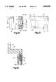
- FIG. 1is a schematic view of a vehicle door embodying a crush sensor constructed in accordance with the present invention
- FIG. 2is a view in the direction of line 2--2 in FIG. 1 and showing parts of the vehicle door removed;
- FIG. 3is an enlarged perspective view of the crush sensor of FIGS. 1 and 2;
- FIG. 4Ais a sectional view taken approximately along line 4A--4A in FIG. 3;
- FIG. 4Bis a sectional view taken approximately along line 4B--4B in FIG. 4A;
- FIG. 4Cis a view taken along line 4C--4C in FIG. 4A;
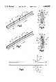
- FIG. 5is a view of the crush sensor of FIG. 3 but with certain parts removed;
- FIG. 6is a sectional view taken approximately along line 6--6 in FIG. 5;
- FIG. 7is a view similar to FIG. 5 but showing the crush sensor in a deformed condition
- FIG. 8is a sectional view taken approximately along line 8--8 in FIG. 7;
- FIG. 9is a schematic diagram of an electrical circuit embodying a crush sensor constructed in accordance with the present invention.
- the present inventionis directed to a crush sensor for use in a vehicle.
- the specific construction of the crush sensormay vary.
- a crush sensor 10is mounted on a vehicle door 12 having an outer skin 13 as shown in FIGS. 1 and 2.
- the crush sensor 10is spaced apart from the outer skin 13 of the vehicle door 12 by a distance D.
- the crush sensor 10is mounted on the vehicle door 12 in a generally horizontal orientation, i.e., along the forward direction of travel (shown with arrow A) and the rearward direction of travel (shown with arrow B) of the vehicle.
- An air bag assembly 14 including an inflatable air bag 16is also mounted on the vehicle door 12.
- the air bag 16is stored in a tightly folded condition (illustrated in solid lines in FIGS. 1 and 2) and, upon the occurrence of a side impact of sufficient severity, is rapidly inflated to a deployed condition (illustrated in dashed lines in FIGS. 1 and 2) to protect a vehicle occupant from violently striking parts of the vehicle door 12 as a result of the side impact.
- the air bag assembly 14is described herein as being mounted on the vehicle door 12, it is contemplated that the air bag assembly may be located in a vehicle seat, a B-pillar of the vehicle, or at another suitable location in the vehicle.
- An actuatable inflator(not shown) contains a source of gas, such as a pyrotechnic gas generating material or a quantity of stored gas or a combination of stored gas and gas generating material. When actuated, the inflator provides gas which is directed into the interior of the air bag 16 to inflate the air bag 16. The inflator actuates to inflate the air bag 16 to protect a vehicle occupant when the crush sensor 10 is deformed in response to the vehicle door 12 being deformed in an impact against the vehicle door 12.
- a source of gassuch as a pyrotechnic gas generating material or a quantity of stored gas or a combination of stored gas and gas generating material.
- the crush sensor 10comprises an elongated plastic sleeve 45 which is supportingly mounted at its ends between a pair of mounting brackets 40, 42.
- the plastic sleeve 45is extruded with a cross sectional shape as best illustrated in FIG. 4A.
- the mounting brackets 40, 42are preferably made of a high strength plastic material.
- the mounting bracket 40has a pair of mounting holes 41 (best illustrated in FIG. 4C) which allow the crush sensor 10 to be mounted on the vehicle door 12 using suitable nuts and bolts.
- the other mounting bracket 42has a pair of mounting holes 43 (best illustrated in FIG. 3) which allow the crush sensor 10 to be mounted on the vehicle door 12 using suitable nuts and bolts.
- FIG. 5the direction of looking at the crush sensor 10 is the same as in FIG. 3.
- the difference between FIG. 3 and FIG. 5is that certain parts including the plastic sleeve 45 and the pair of mounting brackets 40, 42 are removed from FIG. 5 so that the specific construction of the crush sensor 10 is better visualized.
- the crush sensor 10is shown in a normal condition in FIG. 5.
- the crush sensor 10comprises a first elongated metallic member 20 having a width W and a length L.
- the first member 20is located toward an outboard side of the sensor 10 and the outer skin 13 of the vehicle door 12.
- the first member 20includes an elongated contact surface 22 (FIG. 6) along its length L.
- the contact surface 22is concave-shaped as best shown in FIG. 6.
- the crush sensor 10further comprises a second elongated metallic member 30 having a width which is the same as the width W of the first member 20 and a length which is the same as the length L of the first member 20.
- the second member 30is located toward an inboard side of the sensor 10 and the vehicle door 12.
- the first member 20is located between the outer skin 13 of the vehicle door 12 and the second member 30.
- the first and second members 20, 30are disposed inside the plastic sleeve 45 and are supportingly mounted between the pair of mounting brackets 40, 42. Specifically, one end of each of the first and second members 20, 30 is inserted into the mounting bracket 40 as shown in FIG. 4B. The opposite end of each of the first and second members 20, 30 is inserted into the other mounting bracket 42 in the same manner.
- the plastic sleeve 45prevents foreign objects from accidently shorting out the first and second members 20, 30.
- the plastic sleeve 45also functions as an environmental barrier.
- each of the first and second members 20, 30is made of an electrically conductive metallic material such as plated low carbon steel.
- the length L of the first and second members 20, 30is more than 50 percent of the length of the vehicle door 12, as measured in the forward and rearward directions of travel of the vehicle.
- the length L of the first and second members 20, 30is about 85 percent of the length of the vehicle door 12. Greater sensitivity is provided when the length L of the first and second members 20, 30 is increased.
- the second member 30is closely spaced from, and parallel to, the first member 20. Moreover, the second member 30 includes an elongated contact surface 32 (FIG. 6) along its length L.
- the contact surface 32includes a narrow, generally planar strip 34 and a longitudinal raised rib 36 which projects from the strip 34 and faces the contact surface 22 along the length L of the first and second members 20, 30. Therefore, the contact surface 32 of the second member 30 (more specifically, rib 36) has a convex cross sectional shape which faces the concave-shaped contact surface 22 of the first member 20.
- the concave-shaped contact surface 22 of the first member 20has opposite outer edges 23, 25 which lie in a flat plane 27 extending through the rib 36 of the contact surface 32 of the second member 30.
- Suitable insulated spacers 50are located between the first and second members 20, 30 along the length L of the first and second members 20, 30.
- the spacers 50may be made of, for example, a plastic material or an elastomeric material.
- the spacers 50electrically isolate the contact surface 22 of the first member 20 from the contact surface 32 of the second member 30.
- a suitable insulatormay be disposed along at least a portion of the length L of the first and second members 20, 30 between the contact surfaces 22, 32 to electrically isolate the contact surfaces 22, 32 from each other.
- a first connector strip 21extends through the mounting bracket 40 (best shown in FIG. 4B).
- the first connector strip 21has opposite ends. One end of the first connector strip 21 is curved towards the first member 20 and electrically contacts the first member 20. The other end of the first connector strip 21 is straight and is connectable to an electrical wire 61 (as schematically shown in FIG. 9) connected to the positive terminal 60 of the vehicle battery.
- a second connector strip 31 located adjacent to the first connector strip 21also extends through the mounting bracket 40.
- the second connector strip 31has opposite ends and is similar in construction to the first connector strip 21.
- One end of the second connector strip 31is curved towards the second member 30 (best shown in FIG. 4B) and electrically contacts the second member 30.
- the other end of the second connector strip 31is straight and is connectable to an electrical wire 64 (as schematically shown in FIG. 9) connected to the air bag assembly 14 which, in turn, is connected to the negative terminal 65 of the vehicle battery.
- the crush sensor 10deforms from the normal condition shown in FIG. 5 to a deformed condition shown in FIG. 7.
- the first and second members 20, 30move toward each other from their positions shown in FIG. 6 to the positions shown in FIG. 8.
- the insulated spacers 50are crushed or deformed.
- the first member 20deforms in such manner that it buckles laterally.
- a surface portion on the contact surface 22 of the first member 20moves into engagement with the rib 36 on the second member 30 abruptly to establish an electrical connection between the first and second members 20, 30.
- the abrupt movement of the surface portion of the contact surface 22 into engagement with the rib 36 on the second member 30results in a prolonged contact closure time between the first and second members 20, 30.
- the electrical connection between the first and second members 20, 30is established such that current flows from the positive terminal 60 of the vehicle battery through the first and second members 20, 30 of the crush sensor 10 to the air bag assembly 14.
- an inflator(not shown) located in the air bag assembly 14 is actuated to inflate the air bag 16 to protect the vehicle occupant.
- the air bag 16is inflated to protect the vehicle occupant upon the vehicle door 12 being crushed in an impact against the vehicle door 12.
- the distance D between the crush sensor 10 and the outer skin 13 of the vehicle door 12should be as short as possible. However, it is desirable that the distance D be not so short that false triggering of the crush sensor 10 occurs.
- a number of advantagesresult by using a crush sensor constructed in accordance with the present invention.
- One advantageis that the crush sensor 10 is sensitive over a relatively wide range of crush areas on the vehicle door 12. This advantage is obtained because the contact surfaces 22, 32 of the first and second members 20, 30 is along more than 50 percent of the length of the vehicle door 12 in the forward and rearward directions of travel of the vehicle.
- Another advantage in using the crush sensor 10 constructed in accordance with the present inventionis that the insulated spacers 50 prevent the contact surface 22 of the first member 20 from electrically connecting with the contact surface 32 of the second member 30 when the vehicle door 12 is subjected to typical, normal vibrations during operation of the vehicle.
- Still another advantageis that the buckling action of the concave-shaped contact surface 22 of the first member 20 during deformation of the crush sensor 10 provides a bounce-free electrical contact with prolonged contact closure time between the first and second members 20, 30.
- the crush sensor 10may be used in conjunction with a safing sensor to actuate an inflator which releases gas to inflate an air bag. It is also contemplated that the crush sensor 10 itself may be used as a safing sensor.
Landscapes
- Engineering & Computer Science (AREA)
- Mechanical Engineering (AREA)
- Air Bags (AREA)
Abstract
Description
Claims (13)
Priority Applications (2)
| Application Number | Priority Date | Filing Date | Title |
|---|---|---|---|
| US08/467,765US5680909A (en) | 1995-06-06 | 1995-06-06 | Crush sensor for use in a vehicle |
| GBGB9610943.4AGB9610943D0 (en) | 1995-06-06 | 1996-05-24 | Crush sensor for use in a vehicle |
Applications Claiming Priority (1)
| Application Number | Priority Date | Filing Date | Title |
|---|---|---|---|
| US08/467,765US5680909A (en) | 1995-06-06 | 1995-06-06 | Crush sensor for use in a vehicle |
Publications (1)
| Publication Number | Publication Date |
|---|---|
| US5680909Atrue US5680909A (en) | 1997-10-28 |
Family
ID=23857079
Family Applications (1)
| Application Number | Title | Priority Date | Filing Date |
|---|---|---|---|
| US08/467,765Expired - LifetimeUS5680909A (en) | 1995-06-06 | 1995-06-06 | Crush sensor for use in a vehicle |
Country Status (2)
| Country | Link |
|---|---|
| US (1) | US5680909A (en) |
| GB (1) | GB9610943D0 (en) |
Cited By (13)
| Publication number | Priority date | Publication date | Assignee | Title |
|---|---|---|---|---|
| US20030156036A1 (en)* | 2000-01-29 | 2003-08-21 | Frank-Juergen Stuetzler | Sensor arrangement |
| WO2004076244A1 (en)* | 2003-02-26 | 2004-09-10 | Hwanmyoung Kim | Transform sensing switch for airbag system |
| US20060162984A1 (en)* | 2005-01-25 | 2006-07-27 | Trw Automotive U.S. Llc | Crash sensor for sensing an impact to a vehicle in response to reduced light intensity and an associated method |
| US20060180380A1 (en)* | 2005-02-11 | 2006-08-17 | Trw Automotive U.S. Llc | Sensor assembly including a sensing channel having a void and an associated method |
| US7199315B1 (en)* | 2004-02-05 | 2007-04-03 | Streamlight, Inc. | Pressure actuated electrical switch |
| US20070088479A1 (en)* | 2005-10-19 | 2007-04-19 | Trw Automotive U.S. Llc | Apparatus with sensor assembly for sensing a vehicle crash condition and associated method |
| US20080023082A1 (en)* | 2004-06-24 | 2008-01-31 | Josef Schucker | Device For Conveying Viscous Material |
| US20080173677A1 (en)* | 2007-01-19 | 2008-07-24 | Hickok Alan P | Valve carrier ring assembly |
| US20090102631A1 (en)* | 2007-10-22 | 2009-04-23 | Takata Corporation | Occupant Restraint system |
| US20090254238A1 (en)* | 2008-04-04 | 2009-10-08 | Dr. Ing. H.C.F. Porsche Aktiengesellschaft | Impact detection arrangement |
| US20150165998A1 (en)* | 2013-12-13 | 2015-06-18 | Denso Corporation | Side collision detection device for vehicle |
| DE102014223954A1 (en)* | 2014-11-25 | 2016-05-25 | Bayerische Motoren Werke Aktiengesellschaft | Method for determining a defective component of a vehicle |
| US20170174162A1 (en)* | 2015-12-18 | 2017-06-22 | Sungwoo Hitech Co., Ltd. | Impact sensor assembly for active hood system |
Citations (8)
| Publication number | Priority date | Publication date | Assignee | Title |
|---|---|---|---|---|
| FR1273397A (en)* | 1960-07-22 | 1961-10-13 | Device for determining the speed of a motor vehicle at the time of a collision | |
| DE2643505A1 (en)* | 1976-09-28 | 1978-03-30 | Walter Holzer | Automatic door actuating and safety mechanism - has flexible edge actuating circuit producing automatic electrical opening signals |
| US4995639A (en)* | 1988-09-02 | 1991-02-26 | Automotive Technologies International, Inc. | Vehicle crush zone crash sensor |
| US5023418A (en)* | 1988-08-05 | 1991-06-11 | Karlheinz Beckhausen | Safety edge switch |
| FR2671525A1 (en)* | 1991-01-16 | 1992-07-17 | Jaeger | Device for detecting impacts on motor vehicles |
| WO1993001071A1 (en)* | 1991-07-09 | 1993-01-21 | Automotive Technologies International, Inc. | Improved tape switch crush sensor |
| US5307896A (en)* | 1991-08-13 | 1994-05-03 | Nippondenso Co., Ltd. | Collision detection sensor |
| US5335749A (en)* | 1991-08-13 | 1994-08-09 | Nippondenso Co., Ltd. | Crash sensor |
- 1995
- 1995-06-06USUS08/467,765patent/US5680909A/ennot_activeExpired - Lifetime
- 1996
- 1996-05-24GBGBGB9610943.4Apatent/GB9610943D0/enactivePending
Patent Citations (8)
| Publication number | Priority date | Publication date | Assignee | Title |
|---|---|---|---|---|
| FR1273397A (en)* | 1960-07-22 | 1961-10-13 | Device for determining the speed of a motor vehicle at the time of a collision | |
| DE2643505A1 (en)* | 1976-09-28 | 1978-03-30 | Walter Holzer | Automatic door actuating and safety mechanism - has flexible edge actuating circuit producing automatic electrical opening signals |
| US5023418A (en)* | 1988-08-05 | 1991-06-11 | Karlheinz Beckhausen | Safety edge switch |
| US4995639A (en)* | 1988-09-02 | 1991-02-26 | Automotive Technologies International, Inc. | Vehicle crush zone crash sensor |
| FR2671525A1 (en)* | 1991-01-16 | 1992-07-17 | Jaeger | Device for detecting impacts on motor vehicles |
| WO1993001071A1 (en)* | 1991-07-09 | 1993-01-21 | Automotive Technologies International, Inc. | Improved tape switch crush sensor |
| US5307896A (en)* | 1991-08-13 | 1994-05-03 | Nippondenso Co., Ltd. | Collision detection sensor |
| US5335749A (en)* | 1991-08-13 | 1994-08-09 | Nippondenso Co., Ltd. | Crash sensor |
Non-Patent Citations (4)
| Title |
|---|
| 1991 advertisement of Automotive Technologies International, Inc. entitled "Crush Switch Air Bag Crash Sensor". |
| 1991 advertisement of Automotive Technologies International, Inc. entitled Crush Switch Air Bag Crash Sensor .* |
| SAE Technical Paper No. 920122 entitled "Crush Sensor For Use With Automotive Air Bag Systems", Feb. 24-28. 1992. |
| SAE Technical Paper No. 920122 entitled Crush Sensor For Use With Automotive Air Bag Systems , Feb. 24 28. 1992.* |
Cited By (20)
| Publication number | Priority date | Publication date | Assignee | Title |
|---|---|---|---|---|
| US20030156036A1 (en)* | 2000-01-29 | 2003-08-21 | Frank-Juergen Stuetzler | Sensor arrangement |
| US6693549B2 (en)* | 2000-01-29 | 2004-02-17 | Robert Bosch Gmbh | Sensor arrangement |
| WO2004076244A1 (en)* | 2003-02-26 | 2004-09-10 | Hwanmyoung Kim | Transform sensing switch for airbag system |
| US7199315B1 (en)* | 2004-02-05 | 2007-04-03 | Streamlight, Inc. | Pressure actuated electrical switch |
| US20080023082A1 (en)* | 2004-06-24 | 2008-01-31 | Josef Schucker | Device For Conveying Viscous Material |
| US20060162984A1 (en)* | 2005-01-25 | 2006-07-27 | Trw Automotive U.S. Llc | Crash sensor for sensing an impact to a vehicle in response to reduced light intensity and an associated method |
| US20060180380A1 (en)* | 2005-02-11 | 2006-08-17 | Trw Automotive U.S. Llc | Sensor assembly including a sensing channel having a void and an associated method |
| US7445073B2 (en) | 2005-02-11 | 2008-11-04 | Trw Automotive U.S. Llc | Sensor assembly including a sensing channel having a void and an associated method |
| US20070088479A1 (en)* | 2005-10-19 | 2007-04-19 | Trw Automotive U.S. Llc | Apparatus with sensor assembly for sensing a vehicle crash condition and associated method |
| US20080173677A1 (en)* | 2007-01-19 | 2008-07-24 | Hickok Alan P | Valve carrier ring assembly |
| US20090102631A1 (en)* | 2007-10-22 | 2009-04-23 | Takata Corporation | Occupant Restraint system |
| US7982590B2 (en)* | 2007-10-22 | 2011-07-19 | Takata Coporation | Occupant restraint system |
| US20090254238A1 (en)* | 2008-04-04 | 2009-10-08 | Dr. Ing. H.C.F. Porsche Aktiengesellschaft | Impact detection arrangement |
| US8412415B2 (en)* | 2008-04-04 | 2013-04-02 | Dr. Ing. H.C.F. Porsche Aktiengesellschaft | Impact detection arrangement |
| US20150165998A1 (en)* | 2013-12-13 | 2015-06-18 | Denso Corporation | Side collision detection device for vehicle |
| DE102014223954A1 (en)* | 2014-11-25 | 2016-05-25 | Bayerische Motoren Werke Aktiengesellschaft | Method for determining a defective component of a vehicle |
| US10152833B2 (en) | 2014-11-25 | 2018-12-11 | Bayerische Motoren Werke Aktiengesellschaft | Method for determining a defective component of a vehicle |
| DE102014223954B4 (en) | 2014-11-25 | 2022-12-29 | Bayerische Motoren Werke Aktiengesellschaft | Method, diagnostic module and vehicle for determining a defective component of a vehicle |
| US20170174162A1 (en)* | 2015-12-18 | 2017-06-22 | Sungwoo Hitech Co., Ltd. | Impact sensor assembly for active hood system |
| US9840217B2 (en)* | 2015-12-18 | 2017-12-12 | Sungwoo Hitech Co., Ltd. | Impact sensor assembly for active hood system |
Also Published As
| Publication number | Publication date |
|---|---|
| GB9610943D0 (en) | 1996-07-31 |
Similar Documents
| Publication | Publication Date | Title |
|---|---|---|
| US5680909A (en) | Crush sensor for use in a vehicle | |
| EP0527492B1 (en) | Crash sensor | |
| US6009970A (en) | Tape switch crush sensor | |
| US6234519B1 (en) | Arrangements and methods for controlling deployment of a vehicular occupant restraint device | |
| US6744354B2 (en) | System for sensing whether an object struck in a collision is a pedestrian | |
| US6693549B2 (en) | Sensor arrangement | |
| US6557889B2 (en) | Crush velocity sensing vehicle crash sensor | |
| US6169479B1 (en) | Vehicular deformation sensor system | |
| EP1171329B1 (en) | Air bag cover with vehicle operator position sensor and horn switch | |
| KR20080068002A (en) | Collision Detection System and Protection System Using the Same | |
| US6328126B2 (en) | Crush sensing vehicle crash sensor | |
| JPH08216826A (en) | Hood airbag sensor system | |
| US6206129B1 (en) | Crush sensing vehicle crash sensor | |
| US20150165998A1 (en) | Side collision detection device for vehicle | |
| US20200266589A1 (en) | Connector-integrated grounding systems and methods | |
| JPH0789405A (en) | Impact detecting sensor | |
| JP2930784B2 (en) | Collision detection sensor | |
| JP3273679B2 (en) | Steering wheel | |
| EP0890488B1 (en) | A system for controlling the activation of an air-bag in a motor-vehicle | |
| JPH07117621A (en) | Sensor for passenger protection device | |
| KR960002056Y1 (en) | Impact sensor | |
| JPH051628U (en) | Sensor for passenger protection device | |
| JPH0642462U (en) | Shock detector | |
| JPH05155310A (en) | Collision sensor mounting structure for side air bag device | |
| JPH07181197A (en) | Impact detection sensor |
Legal Events
| Date | Code | Title | Description |
|---|---|---|---|
| AS | Assignment | Owner name:TRW TECHNAR INC., CALIFORNIA Free format text:ASSIGNMENT OF ASSIGNORS INTEREST;ASSIGNOR:LOFY, JOHN D.;REEL/FRAME:007551/0897 Effective date:19950601 | |
| FEPP | Fee payment procedure | Free format text:PAYOR NUMBER ASSIGNED (ORIGINAL EVENT CODE: ASPN); ENTITY STATUS OF PATENT OWNER: LARGE ENTITY | |
| STCF | Information on status: patent grant | Free format text:PATENTED CASE | |
| FPAY | Fee payment | Year of fee payment:4 | |
| AS | Assignment | Owner name:JPMORGAN CHASE BANK, NEW YORK Free format text:THE US GUARANTEE AND COLLATERAL AGREEMENT;ASSIGNOR:TRW TECHNAR INC.;REEL/FRAME:013943/0279 Effective date:20030228 | |
| FPAY | Fee payment | Year of fee payment:8 | |
| FPAY | Fee payment | Year of fee payment:12 | |
| AS | Assignment | Owner name:JPMORGAN CHASE BANK, N.A., AS COLLATERAL AGENT, NE Free format text:SECURITY AGREEMENT;ASSIGNORS:TRW VEHICLE SAFETY SYSTEMS INC.;TRW AUTOMOTIVE U.S. LLC;KELSEY-HAYES COMPANY;REEL/FRAME:029529/0534 Effective date:20120928 | |
| AS | Assignment | Owner name:TRW AUTOMOTIVE U.S. LLC, MICHIGAN Free format text:RELEASE OF SECURITY INTEREST;ASSIGNOR:JPMORGAN CHASE BANK, N.A.;REEL/FRAME:031645/0697 Effective date:20131028 Owner name:KELSEY-HAYES COMPANY, MICHIGAN Free format text:RELEASE OF SECURITY INTEREST;ASSIGNOR:JPMORGAN CHASE BANK, N.A.;REEL/FRAME:031645/0697 Effective date:20131028 Owner name:TRW VEHICLE SAFETY SYSTEMS INC., MICHIGAN Free format text:RELEASE OF SECURITY INTEREST;ASSIGNOR:JPMORGAN CHASE BANK, N.A.;REEL/FRAME:031645/0697 Effective date:20131028 Owner name:TRW INTELLECTUAL PROPERTY CORP., MICHIGAN Free format text:RELEASE OF SECURITY INTEREST;ASSIGNOR:JPMORGAN CHASE BANK, N.A.;REEL/FRAME:031645/0697 Effective date:20131028 |